1
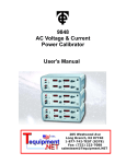
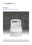
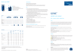
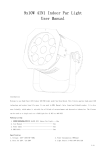
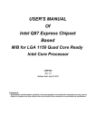
Vector jump protection
function block description
Document ID: VERSION 1.0
Budapest, March 2012.
IED-EP+ Vector jump protection
User’s manual version information
Version
Version 1.0
VERSION 1.0
Date
07.03.2012.
Modification
First edition
Compiled by
Petri
2/10
IED-EP+ Vector jump protection
CONTENTS
1
Vector jump protection function ...........................................................................................4
1.1
Application ....................................................................................................................4
1.2
Mode of operation ........................................................................................................4
1.3
Structure of the vector jump protection algorithm ........................................................5
1.3.1
The Fourier calculation .............................................................................................7
1.3.2
The symmetrical component calculation ..................................................................7
1.3.3
The frequency calculation.........................................................................................7
1.3.4
The vector jump calculation ......................................................................................8
1.3.5
The decision logic .....................................................................................................8
1.4
Technical summary ......................................................................................................9
1.4.1
Technical data .......................................................................................................9
1.4.2
The parameters .....................................................................................................9
1.4.3
Binary output status signal ................................................................................. 10
1.4.4
Binary input status signals ................................................................................. 10
1.4.5
The function block .............................................................................................. 10
VERSION 1.0
3/10
IED-EP+ Vector jump protection
1 Vector jump protection function
1.1 Application
The modern electric power systems include an increasing number of small generators
(distributed generation system). There can be several events in the network resulting that the
small generators get disconnected from the system, and the small generator supplies some
consumer only, remaining in the electric “island” (unintended islanding).
If a small generator remains in an island with some consumers, it is highly possible that the
balance of the generated and consumed active and reactive power is not fulfilled. This results
changing of the frequency and/or voltage, accordingly the voltage vector position of the island
is changing, related to that of the disconnected grid. An automatic reclosing of the circuit
breaker at an unfavorable vector position can result high currents and serious damages. To
prevent these damages a protection is needed to detect the islanding and to disconnect the
generator from the island.
One of the protection methods to detect unintended islanding is this vector jump protection
function.
1.2 Mode of operation
When an unintended islanding occurs then the induced voltage inside the generator (EMF)
may not change abruptly. As a consequence, on other locations within the island (at the
connection point of the generator, at the bus-bar or at the consumer) a sudden change of the
voltage vector can be detected. It means that the vector „jumps”, the time period of the
sinusoid at the moment of the change can be shorter or longer than the previous or
subsequent ones.
The main task of the vector jump protection function is to detect the unintended islanding,
when the generator with some consumer area is disconnected from the electric power grid.
The application of the vector jump function needs careful setting. One of the problems is
caused by the scenario, when the balance of the electric power before and after the islanding
is not changing significantly (the generated and consumed power within the island is
balanced). Accordingly the limit for jump detection must be set to a low angle value, but there
is no guarantee that the islanding is detected by this method. At the same time, however, a
switching of a relatively large consumer can cause also a vector jump. To prevent the
unwanted trip, in this scenario the setting limit for the vector jump angle should be selected
large.
For vector jump detection the function must be enabled, and the measured positive sequence
voltage component must be above a minimum value.
If a fault occurs on the network, the voltage vector jumps. In this case a decision is needed if
the role of the vector jump function is the fault protection, or the fault is to be cleared at other
locations of the network. For excluding the operation in case of asymmetrical faults, the
negatives sequence and zero sequence voltage components must be supervised. If they are
above the setting, asymmetrical fault is detected and the operation of the vector jump
protection function is blocked.
For vector jump detection the function must be enabled, and the measured voltage must be
above a minimum value. For disabling the operation in case of low voltage an additional
undervoltage binary input is provided.
VERSION 1.0
4/10
IED-EP+ Vector jump protection
If the network frequency is deviating from the nominal frequency then the voltage vector
rotates slowly in the complex coordinate system. As the vector jump detection function is
based on comparison of the vectors of the actual and some previous states, the vector
rotation caused by the frequency deviation must be compensated. For this purpose also the
network frequency is measured continuously.
1.3 Structure of the vector jump protection algorithm
The scheme of operation of the vector jump protection function is shown in Figure
Fourier
calculation
nn
UL
UL
UL
Symmetrical
component
calculation
UL1
Pos
UL2
Neg
UL3
Zero
1-1.
Vector jump
Vector
jump
calculation
Decision
logic
Bin
output
s
Frequency
calculation
Bin
inputs
Parameter
Figure 1-1 Structure of the vector jump protection algorithm
The inputs are
• the three phase voltages,
• parameters,
• status signals.
NOTE: in some device configurations also the residual voltage is measured separately. In this
case the zero sequence voltage component is calculated directly from the residual voltage.
For the actual realization please consult the configuration manual delivered with the device.
The output is
• the binary output status signal for tripping.
The software modules of the vector jump protection function are:
VERSION 1.0
5/10
IED-EP+ Vector jump protection
Modules for processing the input signals:
Fourier calculations
These modules calculate the basic Fourier components of the phase voltages individually.
(They are not part of the Vector jump function.)
Positive sequence component calculation
This module calculates the positive sequence voltage component based on the basic Fourier
components of the phase voltages. (It is not part of the Vector jump function). The magnitude
of the positive sequent voltage component must be above the setting to enable the operation.
Negative sequence component calculation
This module calculates the negative sequence voltage component based on the basic Fourier
components of the phase voltages. (It is not part of the Vector jump function). If the
magnitude of the negative sequent voltage component is above the setting then an
asymmetrical fault is supposed and the operation of the vector jump protection function is
blocked.
Zero sequence component calculation
This module calculates the zero sequence voltage component based on the basic Fourier
components of the phase voltages. (It is not part of the Vector jump function). If the
magnitude of the zero sequent voltage component is above the setting then an asymmetrical
fault is supposed and the operation of the vector jump protection function is blocked.
Frequency calculation
This module calculates the frequency. (It is not part of the Vector jump function.) Based on
the frequency value the calculated angle of the vector jump is corrected, if the frequency
deviates from the rated frequency.
Modules for vector jump detection and decision:
Vector jump calculation
This module calculates the vector jump, based on the Fourier components of the positive
sequence voltage component.
Decision logic
The decision logic module combines the status signals to generate the trip command of the
function.
The following description explains the details of the individual components.
VERSION 1.0
6/10
IED-EP+ Vector jump protection
1.3.1 The Fourier calculation
These modules calculate the basic Fourier components of the phase voltages individually.
They are not part of the vector jump function; they belong to the preparatory phase.
The inputs are the sampled values of the three phase voltages (UL1, UL2, UL3)
The outputs are the basic Fourier components of the analyzed voltages (UL1Four, UL2Four,
UL3Four).
NOTE: in some device configurations also the residual voltage is measured separately. In this
case the zero sequence voltage component is calculated directly from the residual voltage.
For the actual realization please consult the configuration manual delivered with the device.
1.3.2 The symmetrical component calculation
These modules (Positive sequence component calculation, negative sequence component
calculation, zero sequence component calculation) calculate the magnitudes and phase
angles of the symmetrical components, based on the theory of the component calculation.
The magnitude of the positive sequent component is used to enable the vector jump decision.
The magnitudes of the negative and zero sequence components can disable the vector jump
decision.
The angle of the vector jump is calculated based on the angle of the positive sequence
component and the angle of this component two periods before. The rotation of the vector
caused by the frequency deviation is compensated based on the frequency input.
NOTE: in some device configurations also the residual voltage is measured separately. In this
case the zero sequence voltage component is calculated directly from the residual voltage.
For the actual realization please consult the configuration manual delivered with the device.
The inputs of this module are the basic Fourier components of the phase voltages (UL1Four,
UL2Four, IUL3Four).
The outputs of this module are the basic Fourier components of the positive, negative and
zero sequence voltage components, given in terms of magnitudes and phase angles.
1.3.3 The frequency calculation
Depending on the hardware-software configuration, the frequency measurement is usually
based on channel No. 1 of the voltage input module. In some applications, the frequency is
measured based on the weighted sum of the phase voltages. For the actual realization please
consult the configuration manual delivered with the device.
The accurate frequency measurement is performed by measuring the time period between
two rising edges at zero crossing of a voltage signal. For the acceptance of the measured
frequency, at least four subsequent identical measurements are needed. Similarly, four invalid
measurements are needed to reset the measured frequency to zero. The basic criterion is
that the evaluated voltage should be above 30% of the rated voltage value.
The inputs of this module are assigned voltages channels, according to the device
configuration.
The output of this module is the calculated frequency in mHz units.
VERSION 1.0
7/10
IED-EP+ Vector jump protection
1.3.4 The vector jump calculation
The vector jump is the difference between the phase angle of the actual positive sequence
component and the angle measured two network periods earlier. A vector jump is detected if
the absolute value of the calculated angle difference is above the setting value.
The inputs of this module are the data of the positive sequence voltage, the frequency and
the setting value of the vector jump. The module stores the angles of the positive sequence
voltage component in the memory for two network periods, and calculates the “raw” vector
jump. This value is corrected if the frequency deviates from the rated network frequency.
The binary output of this module is true if the corrected vector jump is above the setting
value.
1.3.5 The decision logic
The decision logic module combines the status signals and parameters to generate the trip
command of the function.
The performed logic is a simple one: a trip command is generated if:
• The calculated vector jump is above the setting value,
• The magnitude of the positive sequence voltage component is above the setting
value,
• The magnitude of the negative sequence voltage component is below the setting
value,
• The magnitude of the zero sequence voltage component is below the setting value,
• The “Blk” binary input does not block the function, and
• The “UVBlk” binary input does not block the function.
The vector jump means that one network frequency period of the voltage sinusoid is shorter
or longer than the previous periods or that of the subsequent periods. This binary information
must be prolonged to generate the trip pulse. The minimum duration of the trip command is
set by a parameter.
NOTE: when checking the pulse duration please consider that the timer parameter defines
the prolongation, the operating time span is added to the pulse duration.
VERSION 1.0
8/10
IED-EP+ Vector jump protection
1.4 Technical summary
1.4.1 Technical data
Function
Pick-up starting accuracy
Blocking voltage
Operate time
Jump>2*setting
Minimum operate time
Pulse duration
Value
Accuracy
< ± 0,5°
< 5%
U>0.2Un
<50 ms
40 ms
150 … 500 ms
<10 ms
Table 1-1 Technical data of the vector jump protection function
1.4.2 The parameters
Enumerated parameters
Parameter name
Title
Selection range
Enabling or disabling the vector jump protection function
VectJmp_Oper_EPar_
Operation
Off,On
Default
Off
Table 1-2 The enumerated parameters of the vector jump protection function
Integer parameters
Parameter name
Title
Unit
Min Max
Step Default
Starting phase difference level setting. If the vector jump is above the setting value, the
function generates a start signal.
VectJmp_PhDiff_IPar_
PhaseDiff Limit
deg
5
25
1
10
Enabling positive voltage level setting. If the measured positive sequence voltage component
is above the setting value, the function enables the trip signal.
VectJmp_UposLim_IPar_
Min PosSeq Voltage
%
10
100
1
30
Blocking negative sequence voltage level setting. If the measured negative sequence voltage
component is above the setting value, the function blocks the trip signal.
VectJmp_UnegLim_IPar_
Max NegSeq Voltage
%
5
50
1
10
Blocking zero sequence voltage level setting. If the measured voltage is above the setting
value, the function blocks the trip signal.
VectJmp_UoLim_IPar_
Max ZeroSeq Voltage
%
1
30
1
5
Table 1-3 Integer parameters of the vector jump protection function
Timer parameter
Parameter name
Title
Trip command pulse duration
VectJmp_Pulse_TPar_
Pulse Duration
Unit
Min
Max
Step
Default
msec
150
500
1
150
Table 1-4 Timer parameter of the vector jump protection function
VERSION 1.0
9/10
IED-EP+ Vector jump protection
1.4.3 Binary output status signal
The binary output status signal of vector jump protection function is shown in Table 1-5.
Binary status signal
VectJmp_Trip_GrI_
Title
Trip
Explanation
Trip command of the function
Table 1-5 The binary output status signals of the vector jump protection function
1.4.4 Binary input status signals
Binary input signals
The vector jump protection function has binary input signals, which serve the purpose of
disabling the function. The conditions of disabling are defined by the user, applying the
graphic equation editor.
Binary status signal
VectJmp_Blk_GrO_
Title
Blk
VectJmp_UVBlk_GrO_
UVBlk
Explanation
General blocking status signal
External under-voltage blocking
status signal
Table 1-6 The binary input signal of vector jump protection function
1.4.5 The function block
The function block of vector jump protection function is shown in Figure 1-2. This block shows
all binary input and output status signals that are applicable in the graphic logic editor.
Figure 1-2 The function block of vector jump protection function
VERSION 1.0
10/10