1
E4-DRFP
configuration description
(Type: DTIVA)
Document ID: PP-13-21041
Budapest, June 2015
E4-DRFP configuration description
User’s manual version information
Version
1.0
Date
6/2/2015
Modification
First edition
DTIVA-E4-DRFP_CONFIG_V1.0
Compiled by
Seida
2/60
E4-DRFP configuration description
CONTENTS
1
Configuration description .....................................................................................................4
1.1
Application ....................................................................................................................4
1.1.1
Protection functions ..............................................................................................4
1.1.2
Measurement functions.........................................................................................5
1.1.3
Hardware configuration .........................................................................................6
1.1.4
The applied hardware modules ............................................................................6
1.2
Meeting the device .......................................................................................................7
1.3
Software configuration .................................................................................................8
1.3.1
The implemented functions ...................................................................................8
1.3.2
Protection functions ..............................................................................................9
1.3.2.1 Railway distance protection function (DIS21R) ........................................................... 9
1.3.2.2 Teleprotection function (SCH85) ............................................................................... 11
1.3.2.3 Switch onto fault condition function (SOTFCond) ..................................................... 16
1.3.2.4 Overcurrent function for railway application (TOC51R) ........................................... 17
1.3.2.5 Line thermal protection function for railway application (TTR49R).......................... 20
1.3.2.6 Definite time overvoltage function for railway application (TOV59R)...................... 24
1.3.2.7 Definite time undervoltage function for railway application (TUV27R) .................... 25
1.3.2.8 Trip logic function block (TRC94) ............................................................................. 26
1.3.2.9 Automatic reclosing function for medium voltage networks (REC79MV) ................ 27
1.3.2.10
Circuit breaker wear function (CBWear) ................................................................ 30
1.3.3
Control functions ................................................................................................ 33
1.3.3.1 Circuit breaker control function block (CB1Pol) ........................................................ 33
1.3.4
Measuring functions ........................................................................................... 36
1.3.4.1 Current input function (CT4) ...................................................................................... 37
1.3.4.2 Voltage input function (VT4) ..................................................................................... 39
1.3.4.3 Line measurement function (MXU) ............................................................................ 42
1.3.5
Disturbance recorder ......................................................................................... 46
1.3.6
Event recorder ................................................................................................... 49
1.3.7
TRIP contact assignment ................................................................................... 51
1.3.8
Special logics ..................................................................................................... 52
1.3.8.1 Low gas logic .............................................................................................................. 52
1.3.8.2 VT midget CB logic .................................................................................................... 52
1.3.8.3 Starting and external blocking of the Automatic reclosing function........................... 52
1.3.8.4 Manual close commands ............................................................................................. 53
1.3.8.5 Failure signalling ........................................................................................................ 53
1.4
LCD screens.............................................................................................................. 53
1.4.1
Schema .............................................................................................................. 54
1.4.2
Control................................................................................................................ 54
1.5
LED assignment ........................................................................................................ 55
2
External connection .......................................................................................................... 56
3
Connection assignment .................................................................................................... 57
DTIVA-E4-DRFP_CONFIG_V1.0
3/60
E4-DRFP configuration description
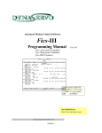
1 Configuration description
The E4-DRFP (Digital Railway Feeder Protection) protection device is a member of the
EuroProt+ product line, made by Protecta Co. Ltd. The EuroProt+ type devices are complex
and modular protections in respect of hardware and software. The modules are assembled
and configured according to the requirements, and then the software determines the
functions. This manual describes the specific application of the E4-DRFP factory
configuration.
1.1 Application
The members of the DTIVA product line are configured to protect and control the elements of
the medium voltage networks. The E4-DRFP configuration can be applied for all protection
and auxiliary functions for single phase AC traction supply systems.
1.1.1 Protection functions
The devices with E4-DRFP configuration measure the current and the voltage of the railway
overhead wire. These measurements allow the Railway distance protection function, which is
the main function of this application, extended with Teleprotection and Switch onto fault and
Fault locator functions.
The configured protection functions are listed in the Table below.
Protection functions
IEC
Railway distance protection
Overcurrent protection
Thermal overload
Definite time overvoltage protection
Definite time undervoltage protection
Auto-reclose
Circuit breaker wear
Teleprotection
Switch onto fault logic
Z<
I>
T>
U>
U<
0->1
ANSI
21
51
49
59
27
79
85
Table 1 The protection functions of the E4-DRFP configuration
DTIVA-E4-DRFP_CONFIG_V1.0
4/60
E4DRFP
X
X
X
X
X
X
X
X
X
E4-DRFP configuration description
The configured functions are drawn symbolically in the Figure below.
Ubus
E4-DRFP
79
Close
Trip
I
51
21
27
I
59
49
Measured values:
U, I, P, Q, S, cosφ, f
Recording features:
Event Recording
Disturbance Recording
Figure 1 Implemented protection functions
1.1.2 Measurement functions
Based on the hardware inputs the measurements listed in Table below are available.
Measurement functions
E4-DRFP
Current (I (CT – Z<, IDMT), I (CT – Th. Ol.))
Voltage and frequency
Power (P, Q, S, cosφ)
Circuit breaker wear
Supervised trip contacts (TCS)
X
X
X
X
X
Table 2 The measurement functions of the E4-DRFP configuration
DTIVA-E4-DRFP_CONFIG_V1.0
5/60
E4-DRFP configuration description
1.1.3 Hardware configuration
The minimum number of inputs and outputs are listed in the Table below.
Hardware configuration
Mounting
Panel instrument case
Current inputs (4th channel can be sensitive)
Voltage inputs
Digital inputs
Digital outputs
Fast trip outputs
Temperature monitoring (RTDs) *
ANSI
E4-DRFP
38 / 49T
Op.
X
4
4
12
8
2
Op.
Table 3 The basic hardware configuration of the E4-DRFP configuration
The basic module arrangement of the E4-DRFP configuration is shown below.
Figure 2 Basic module arrangement of the E4-DRFP configuration (84HP, rear view)
1.1.4 The applied hardware modules
The applied modules are listed in Table 4.
The technical specification of the device and that of the modules are described in the
document “Hardware description”.
Module identifier
PSTP+ 2101
O12+ 1101
R8+ 00
VT+ 2211
CT + 5151
CPU+ 1201
Explanation
Power supply modul with trip contacts
Binary input module
Signal relay output module
Analog voltage input module
Analog current input module
Processing and communication module
Table 4 The applied modules of the E4-DRFP configuration
DTIVA-E4-DRFP_CONFIG_V1.0
6/60
E4-DRFP configuration description
1.2 Meeting the device
The basic information for working with the EuroProt+ devices are described in the document
“Quick start guide to the devices of the EuroProt+ product line”.
Figure 3 The 84HP rack of EuroProt+ family
Figure 4 The 42HP rack of EuroProt+ family
DTIVA-E4-DRFP_CONFIG_V1.0
7/60
E4-DRFP configuration description
1.3 Software configuration
1.3.1 The implemented functions
The implemented functions are listed in Table 5. The function blocks are described in details
in separate documents. These are referred to also in this table.
Name
Title
Document
DIS21R
Distance protection for railway
Railway distance
application, function block description
TOC51R
Overcurrent protection for railway
Overcurrent
application, function block description
TTR49R
Line thermal protection function block
Thermal overload
description for railway application
TOV59R
Definite time overvoltage protection
function block description for railway
Overvoltage
application
TUV27R
Definite time undervoltage protection
function block description for railway
Undervoltage
application
REC79MV
MV Autoreclosing
Automatic reclosing function for medium
voltage networks, function block
description
CBWear
Circuit breaker wear monitoring function
Circuit breaker wear
block description for railway application
SCH85
Teleprotection
Teleprotection function block description
SOTFCond
Switch onto fault
Switch-onto-fault preparation function
condition
block description
TRC94
Trip logic
Trip logic function block description
CT4R
CT4 module
Current input function block description
for railway application
VT4R
VT4 module
Voltage input function block description
for railway application
CB1Pol
Circuit breaker
Circuit breaker control function block
descrpition
MXU_LM
Line measurement
Line
measurement
function
block
descrpition
DRE
Distirbance rec
Disturbance recorder function block
description
Reset
Reset
Reset control function block description
Table 5 Implemented functions
DTIVA-E4-DRFP_CONFIG_V1.0
8/60
E4-DRFP configuration description
1.3.2 Protection functions
1.3.2.1 Railway distance protection function (DIS21R)
The distance protection function provides main protection for overhead lines in railway
application. The main features of the function are as follows:
The selected algorithm fits the requirements of the railway overhead line application.
Continuous measurement of impedance in the loop between the overhead line and
the earth.
Impedance calculation is conditional of the values of the current being sufficient. The
current is considered to be sufficient for impedance calculation if it is above the
defined value.
Five independent distance protection zones are configured.
The operating decision is based on polygon-shaped characteristics.
The directional decision is dynamically based on:
o measured loop voltage if it is sufficient for decision,
o voltage samples stored in the memory if they are available,
The operation of any zones can be directional or non-directional if it is optionally
selected.
Non-directional impedance protection function is applied in case of switch-onto-fault.
Distance-to-fault evaluation is implemented (fault locator function).
Binary input signals and conditions can influence the operation:
o blocking/enabling,
o VT failure signal.
jX
Angle 2nd Quad
angle
Zone X
Load Angle
Line Angle
angle
R
R Load
Angle 4th Quad
angle
LdLioad
angle
Zone R
Figure 5 The polygon characteristics of the distance protection function on the
complex plane
DTIVA-E4-DRFP_CONFIG_V1.0
9/60
E4-DRFP configuration description
Technical data
Function
Range
Number of zones
Rated current In
Rated voltage Un
Current effective range
Voltage effective range
Impedance effective range
In=1A
In=5A
Zone static accuracy
Zone angular accuracy
Operate time
Minimum operate time
Reset time
Reset ratio
Accuracy
5
1/5A, parameter setting
100/200V, parameter setting
20 – 2000% of In
±1% of In
2-110 % of Un
±1% of Un
0.1 – 200 Ohm
0.1 – 40 Ohm
48 Hz – 52 Hz
49.5 Hz – 50.5 Hz
Typically 30 ms
<25 ms
16 – 25 ms
1.1
±5%
±5%
±2%
±3 °
±3 ms
Table 6 Technical data of the 5-zone distance protection
Parameters
The parameters of the distance protection function are explained in the following tables.
Enumerated parameters
Parameter name
Title
Selection range
Parameter to select the distance zones, involved in the SOTF function:
DIS21_SOTFMd_EPar_ SOTF Zone Off,Zone1,Zone2,Zone3,Zone4,Zone5
Parameters to select directionality of the individual zones:
Operation
DIS21_Z1_EPar_
Off, Forward, Backward
Zone1
Operation
DIS21_Z2_EPar_
Off, Forward, Backward, NonDirectional
Zone2
Operation
DIS21_Z3_EPar_
Off, Forward, Backward, NonDirectional
Zone3
Operation
DIS21_Z4_EPar_
Off, Forward, Backward, NonDirectional
Zone4
Operation
DIS21_Z5_EPar_
Off, Forward, Backward, NonDirectional
Zone5
Default
Off
Off
Off
Off
Off
Off
Table 7 The enumerated parameters of the distance protection function
Integer parameters
Parameter name
Title
Unit
Min
Max
Step Default
Definition of minimal current enabling impedance calculation:
DIS21_Imin_IPar_
I Base Sens
%
10
30
1
20
nd
Definition of the polygon characteristic angle in the 2 quadrant of the impedance plane:
DIS21_dirRX_IPar_
Angle 2th Quad
deg
0
30
1
15
Definition of the polygon characteristic angle in the 4th quadrant of the impedance plane:
DIS21_dirXR_IPar_
Angle 4nd Quad
deg
0
30
1
15
Definition of the load angle of the polygon characteristic:
DIS21_LdAng_IPar_
Load Angle
deg
0
45
1
30
Definition of the line angle:
DIS21_LinAng_IPar_
Line Angle
deg
45
90
1
75
Table 8 The integer parameters of the distance protection function
DTIVA-E4-DRFP_CONFIG_V1.0
10/60
E4-DRFP configuration description
Floating point parameters
Parameter name
Title
Dim.
R and X setting values for the five zones individually:
DIS21_Z1R_FPar
Zone1 R
ohm
DIS21_Z2R_FPar
Zone2 R
ohm
DIS21_Z3R_FPar
Zone3 R
ohm
DIS21_Z4R_FPar
Zone4 R
ohm
DIS21_Z5R_FPar
Zone5 R
ohm
DIS21_Z1X_FPar
Zone1 X
ohm
DIS21_Z2X_FPar
Zone2 X
ohm
DIS21_Z3X_FPar
Zone3 X
ohm
DIS21_Z4X_FPar
Zone4 X
ohm
DIS21_Z5X_FPar
Zone5 X
ohm
Load encroachment setting:
DIS21_LdR_FPar
R Load
ohm
Min
Max
Default
0.1
0.1
0.1
0.1
0.1
0.1
0.1
0.1
0.1
0.1
200
200
200
200
200
200
200
200
200
200
10
10
10
10
10
10
10
10
10
10
0.1
200
10
Table 9 The floating-point parameters of the distance protection function
Timer parameters
Parameter name
Title
Time delay for the zones individually:
DIS21_Z1Del_TPar_
Zone1 Time Delay
DIS21_Z2Del_TPar_
Zone2 Time Delay
DIS21_Z3Del_TPar_
Zone3 Time Delay
DIS21_Z4Del_TPar_
Zone4 Time Delay
DIS21_Z5Del_TPar_
Zone5 Time Delay
Unit
Min
ms
ms
ms
ms
ms
0
0
0
0
0
Max
60000
60000
60000
60000
60000
Step
Default
1
1
1
1
1
0
400
800
2000
2000
Table 10 The timer parameters of the distance protection function
1.3.2.2 Teleprotection function (SCH85)
The non-unit protection functions, generally distance protection, can have two, three or even
more zones available. These are usually arranged so that the shortest zone corresponds to
an impedance slightly smaller than that of the protected section (underreach) and is normally
instantaneous in operation. Zones with longer reach settings are normally time-delayed to
achieve selectivity.
As a consequence of the underreach setting, faults near the ends of the line are cleared with
a considerable time delay. To accelerate this kind of operation, protective devices at the line
ends exchange logic signals (teleprotection). These signals can be direct trip command,
permissive or blocking signals.
In some applications even the shortest zone corresponds to an impedance larger than that of
the protected section (overreach).
As a consequence of the overreach setting, faults outside the protected line would also cause
an immediate trip command that is not selective. To prevent such unselective tripping,
protective devices at the line ends exchange blocking logic signals.
The combination of the underreach – overreach settings with direct trip command, permissive
of blocking signals facilitates several standard solutions, with the aim of accelerating the trip
command while maintaining selectivity.
The teleprotection function block is pre-programmed for some of these modes of operation.
The required solution is selected by parameter setting; the user has to assign the appropriate
inputs by graphic programming.
DTIVA-E4-DRFP_CONFIG_V1.0
11/60
E4-DRFP configuration description
Similarly, the user has to assign the “send” signal to a relay output and to transmit it to the far
end relay. The trip command is directed graphically to the appropriate input of the trip logic,
which will energize the trip coil.
Depending on the selected mode of operation, the simple binary signal sent and received via
a communication channel can have several meanings:
Direct trip command
Permissive signal
Blocking signal
To increase the reliability of operation, in this implementation of the telecommunication
function the sending end generates a signal, which can be transmitted via two different
channels.
NOTE: the type of the communication channel is not considered here. It can be
Pilot wire
Fiber optic channel
High frequency signal over transmission line
Radio or microwave
Binary communication network
Etc.
The function receives the binary signal via optically isolated inputs. It is assumed that the
signal received through the communication channel is converted to a DC binary signal
matching the binary input requirements.
For the selection of one of the standard modes of operation, the function offers two
enumerated parameters, Operation and PUTT Trip. With the parameter Operation, the
following options are available: PUTT, POTT, Dir. Comparison, Dir. Blocking, DUTT while with
the parameter PUTT Trip: with Start,with Overreach can be set.
Permissive Underreach Transfer Trip (PUTT)
The IEC standard name of this mode of operation is Permissive Underreach Protection
(PUP).
The protection system uses telecommunication, with underreach setting at each section end.
The signal is transmitted when a fault is detected by the underreach zone. Receipt of the
signal at the other end initiates tripping if other local permissive conditions are also fulfilled,
depending on parameter setting.
For trip command generation using the parameter SCH85_PUTT_EPar_ (PUTT Trip), the
following options are available:
with Start
with Overreach
Permissive Underreach Transfer Trip (PUTT) with start
The protection system uses telecommunication, with underreach setting at each section end.
The signal is transmitted when a fault is detected by the underreach zone. The signal is
prolonged by a drop-down timer. Receipt of the signal at the other end initiates tripping in the
local protection if it is in a started state.
DTIVA-E4-DRFP_CONFIG_V1.0
12/60
E4-DRFP configuration description
T
UZSt
Rec1
Rec2
Send
Blk
NOT
CarrFail
NOT
ZSt Fw
Send
AND
OR
Blk
NOT
CarrFail
NOT
SEND
AND
Ztp
RECEIVE
Permissive Underreach Transfer Trip (PUTT) with Overreach
The protection system uses telecommunication, with underreach setting at each section end.
The signal is transmitted when a fault is detected by the underreach zone. The signal is
prolonged by a drop-down timer. Receipt of the signal at the other end initiates tripping if the
local overreaching zone detects fault.
T
UZSt
Rec1
Rec2
Send
Blk
NOT
CarrFail
NOT
OZSt
Send
AND
OR
Blk
NOT
CarrFail
NOT
SEND
AND
Ztp
RECEIVE
Permissive Overreach Transfer Trip (POTT)
The IEC standard name of this mode of operation is Permissive Overreach Protection (POP).
The protection system uses telecommunication, with overreach setting at each section end.
The signal is transmitted when a fault is detected by the overreach zone. This signal is
prolonged if a general trip command is generated. Receipt of the signal at the other end
permits the initiation of tripping by the local overreach zone.
OZSt
GenTr
AND
Blk
NOT
CarrFail
NOT
T
Rec1
Rec2
OR
Send
AND
Sen
d
SEND
DTIVA-E4-DRFP_CONFIG_V1.0
OR
OZSt
Blk
NOT
CarrFail
NOT
RECEIVE
13/60
AND
Ztp
E4-DRFP configuration description
Directional comparison (Dir.Comparison)
The protection system uses telecommunication. The signal is transmitted when a fault is
detected in forward direction. This signal is prolonged if a general trip command is generated.
Receipt of the signal at the other end permits the initiation of tripping by the local protection if
it detected a fault in forward direction.
ZSt Fw
Gen Tr
AND
OR
T
Dir Tr
Blk
NOT
CarrFail
NOT
Rec1
Rec2
Send
AND
OR
ZStFw
Blk
NOT
CarrFail
NOT
SEND
Ztp
AND
RECEIVE
Blocking directional comparison (Dir.Blocking)
The IEC standard name of this mode of operation is Blocking Overreach Protection (BOP).
The protection system uses telecommunication, with overreach setting at each section end.
The blocking signal is transmitted when a reverse external fault is detected. The signal is
prolonged by a drop-down timer. For the trip command, the forward fault detection is delayed
to allow time for a blocking signal to be received from the opposite end. Receipt of the signal
at the other end blocks the initiation of tripping of the local protection. The received signal is
accepted only if the duration is longer then the parameter Min.Block Time, and the signal is
prolonged by a drop-down timer.
OZSt
ZSt Bw
T
T
ZSt Fw
St
Send
ZSt Fw
NOT
Blk
NOT
CarrFail
NOT
AND
Send
Rec 1
Rec 2
OR
OR
T
T
Min Blk
Pro Blk
Blk
NOT
CarrFail
NOT
SEND
DTIVA-E4-DRFP_CONFIG_V1.0
RECEIVE
14/60
NOT
AND
Ztp
E4-DRFP configuration description
Direct underreaching transfer trip (DUTT)
The IEC standard name of this mode of operation is Intertripping Underreach Protection
(IUP). The protection system uses telecommunication, with underreach setting at each
section end. The signal is transmitted when a fault is detected by the underreach zone.
Receipt of the signal at the other end initiates tripping, independent of the state of the local
protection.
T
UZSt
Send
Blk
NOT
CarrFail
NOT
AND
SEND
Technical data
Function
Operate time accuracy
Send
Rec 1
Rec 2
OR
Blk
NOT
CarrFail
NOT
T
Dir Tr
AND
Ztp
RECEIVE
Accuracy
±5% or ±15 ms, whichever is greater
Table 11 Technical data of the Teleprotection function
Parameters
Enumerated parameters
Parameter name
Title
Selection range
Parameter for teleprotection type selection:
Off, PUTT, POTT, Dir. comparison,
SCH85_Op_EPar_
Operation
Dir. blocking, DUTT
Parameter for PUTT type selection:
PUTT
SCH85_PUTT_EPar_
with Start, with Overreach
Trip
Default
Off
with Overreach
Table 12 Enumerated parameters of the Teleprotection function
Timer parameters
Parameter name
Title
Unit
Send signal prolong time:
SCH85_Send_TPar_ Send Prolong time
ms
Received direct trip delay time for DUTT:
Direct Trip delay
SCH85_DirTr_TPar_
ms
DUTT
Forward fault detection delaying for Dir. Blocking:
SCH85_St_TPar_
Z Start delay (block)
ms
Duration limit for Dir. Blocking:
SCH85_MinBlk_TPar
Min. Block time
ms
_
Prolong duration for Dir. Blocking:
SCH85_ProBlk_TPar
Prolong Block time
ms
_
Min
Max
Step
Default
1
10000
1
10
1
10000
1
10
1
10000
1
10
1
10000
1
10
1
10000
1
10
Table 13 Timer parameters of the Teleprotection function
DTIVA-E4-DRFP_CONFIG_V1.0
15/60
E4-DRFP configuration description
1.3.2.3 Switch onto fault condition function (SOTFCond)
Some protection functions, e.g. distance protection, directional overcurrent protection, etc.
need to decide the direction of the fault. This decision is based on the angle between the
voltage and the current. In case of close-in faults, however, the voltage of the faulty loop is
near zero: it is not sufficient for a directional decision. If there are no healthy phases, then the
voltage samples stored in the memory are applied to decide if the fault is forward or reverse.
If the protected object is energized, the close command for the circuit breaker is received in
“dead” condition. This means that the voltage samples stored in the memory have zero
values. In this case the decision on the trip command is based on the programming of the
protection function for the “switch-onto-fault” condition.
This “switch-onto-fault” (SOTF) detection function prepares the conditions for the subsequent
decision. The function can handle both automatic and manual close commands.
The function receives the “Dead line” status signal from the DLD (dead line detection) function
block. After dead line detection, the binary output signal AutoSOTF is delayed by a timer with
a constant 200 ms time delay. After voltage detection (resetting of the dead line detection
input signal), the drop-off of this output signal is delayed by a timer (SOTF Drop Delay) set by
the user. The automatic close command is not used it is not an input for this function.
The manual close command is a binary input signal. The drop-off of the binary output signal
ManSOTF is delayed by a timer (SOTF Drop Delay) set by the user. The timer parameter is
common for both the automatic and manual close command.
The operation of the “switch-onto-fault” detection function is shown in Figure below.
SOTF Cond
t
Deadline
t
200 ms
AutoSOTF cond
Par_SOTF drop-off delay
t
CBClose
ManSOTF cond
The binary input signals of the “switch-onto-fault” detection function are:
CBClose
Manual close command to the circuit breaker,
DeadLine
Dead line condition detected. This is usually the output signal of the
DLD (dead line detection) function block.
The binary output signals of the “switch-onto-fault” detection function are:
AutoSOTF cond
Signal enabling switch-onto-fault detection as a consequence
of an automatic close command,
ManSOTF cond
Signal enabling switch-onto-fault detection as a consequence
of a manual close command.
Technical data
Function
Timer accuracy
Accuracy
±5% or ±15 ms, whichever is greater
Table 14 Technical data of the Switch onto fault condition function
DTIVA-E4-DRFP_CONFIG_V1.0
16/60
E4-DRFP configuration description
Parameters
Timer parameter
Parameter name
Title
Drop-off time delay for the output signals:
SOTF_SOTFDel_TPar_
SOTF Drop Delay
Unit
Min
Max
Step
Default
msec
100
10000
1
1000
Table 15 The timer parameter of the Switch onto fault function
1.3.2.4 Overcurrent function for railway application (TOC51R)
The overcurrent protection function realizes definite time or inverse time characteristics
according to IEC or IEEE standards, based on the current input. The characteristics are
harmonized with IEC 60255-151, Edition 1.0, 2009-08. This function can be applied as main
protection for railway applications or backup or overload protection for high-voltage network
elements.
The definite (independent) time characteristic has a fixed time delay when the current is
above the starting current Is previously set as a parameter.
The standard operating characteristics of the inverse time overcurrent protection function are
defined by the following formula:
k
t (G ) TMS
c when G GS
G 1
GS
where
t(G)(seconds)
k, c
α
G
GS
TMS
1
2
3
4
5
6
7
8
9
10
11
IEC
ref
A
B
C
D
E
F
theoretical operate time with constant value of G,
constants characterizing the selected curve (in seconds),
constants characterizing the selected curve (no dimension),
measured value of the characteristic quantity, Fourier base harmonic
of the current (I_Four),
preset value of the characteristic quantity (TOC51_StCurr_IPar_,
Start current),
preset time multiplier (no dimension).
Title
kr
c
α
IEC Inv
IEC VeryInv
IEC ExtInv
IEC LongInv
ANSI Inv
ANSI ModInv
ANSI VeryInv
ANSI ExtInv
ANSI LongInv
ANSI LongVeryInv
ANSI LongExtInv
0,14
13,5
80
120
0,0086
0,0515
19,61
28,2
0,086
28,55
64,07
0
0
0
0
0,0185
0,1140
0,491
0,1217
0,185
0,712
0,250
0,02
1
2
1
0,02
0,02
2
2
0,02
2
2
Table 16 The constants of the standard dependent time characteristics
The end of the effective range of the dependent time characteristics (G D) is:
G D 20 * G S
Above this value the theoretical operating time is definite:
DTIVA-E4-DRFP_CONFIG_V1.0
17/60
E4-DRFP configuration description
k
t (G ) TM S
c when G G D 20 * G S
G D 1
G S
Additionally a minimum time delay can be defined by parameter TOC51_MinDel_TPar_ (Min
Time Delay). This delay is valid if it is longer than t(G), defined by the formula above.
The inverse characteristic is valid above GT =1,1* Gs. Above this value the function is
guaranteed to operate.
Resetting characteristics:
For IEC type characteristics the resetting is after a fix time delay defined by
TOC51_Reset_TPar_ (Reset delay),
for ANSI types however according to the formula below:
kr
tr (G ) TMS
1 G
GS
where
tr(G)(seconds)
kr
α
G
GS
TMS
1
2
3
4
5
6
7
8
9
10
11
IEC
ref
A
B
C
D
E
F
when G GS
theoretical reset time with constant value of G,
constants characterizing the selected curve (in seconds),
constants characterizing the selected curve (no dimension),
measured value of the characteristic quantity, Fourier base harmonic
of the phase currents,
preset value of the characteristic quantity (TOC51_StCurr_IPar_,
Start current),
preset time multiplier (no dimension).
α
Title
kr
IEC Inv
IEC VeryInv
IEC ExtInv
IEC LongInv
ANSI Inv
ANSI ModInv
ANSI VeryInv
ANSI ExtInv
ANSI LongInv
ANSI LongVeryInv
ANSI LongExtInv
Resetting after fix time delay,
according to preset parameter
TOC51_Reset_TPar_
“Reset delay”
0,46
2
4,85
2
21,6
2
29,1
2
4,6
2
13,46
2
30
2
Table 17 The resetting constants of the standard dependent time characteristics
DTIVA-E4-DRFP_CONFIG_V1.0
18/60
E4-DRFP configuration description
Technical data
Function
Operating accuracy
Value
20 ≤ GS ≤ 1000
Accuracy
<2%
±5% or ±15 ms,
whichever is greater
Operate time accuracy
Reset ratio
Reset time *
Dependent time char.
Definite time char.
Transient overreach
Pickup time *
Overshot time
Dependent time char.
Definite time char.
Influence of time varying value of the
input current (IEC 60255-151)
0,95
< 2% or ±35 ms,
whichever is greater
Approx 60 ms
<2%
< 40 ms
30 ms
50 ms
<4%
* Measured with signal relay contact
Table 18 Technical data of the overcurrent protection function
Parameters
Enumerated parameter
Parameter name
Title
Parameter for type selection
TOC51R_Oper_EPar
_
Operation
Selection range
Default
Off, Definite Time, IEC Inv,
IEC VeryInv, IEC ExtInv, IEC LongInv, ANSI
Inv, ANSI ModInv, ANSI VeryInv, ANSI ExtInv,
ANSI LongInv, ANSI LongVeryInv,
ANSI LongExtInv
Off
Table 19 The enumerated parameters of the overcurrent protection function
Integer parameter
Parameter name
Title
Starting current parameter:
Unit
Min
Max
Step
Default
TOC51R_StCurr_IPar_
%
10
1000
1
50
Start Current
Table 20 The integer parameters of the overcurrent protection function
Float parameter
Parameter name
Title
Unit
Time multiplier of the inverse characteristics (OC module)
TOC51R_Multip_FPar_
Time Multiplier
Min
Max
Step
Default
0.05
999
0.01
1.0
Table 21 Float parameter of the OC function block
Timer parameters
Parameter name
Title
Unit
Minimal time delay for the inverse characteristics:
TOC51R_MinDel_TPar_ Min Time Delay *
msec
Definite time delay:
Definite Time Delay
TOC51R_DefDel_TPar_
msec
**
Reset time delay for the IEC type inverse characteristics:
TOC51R_Reset_TPar_
Reset Time*
msec
Min
Max
Step
Default
0
60000
1
100
0
60000
1
100
0
60000
1
100
*Valid for inverse type characteristics
**Valid for definite type characteristics only
Table 22 Timer parameters of the overcurrent protection function
DTIVA-E4-DRFP_CONFIG_V1.0
19/60
E4-DRFP configuration description
1.3.2.5 Line thermal protection function for railway application (TTR49R)
Basically, line thermal protection measures the sampled current. RMS values are calculated
and the temperature calculation is based on the RMS value of the current.
The temperature calculation is based on the step-by-step solution of the thermal differential
equation. This method yields “overtemperature”, meaning the temperature above the ambient
temperature (of the environment). Accordingly, the temperature of the protected object is the
sum of the calculated “overtemperature” and the ambient temperature.
The ambient temperature can be measured using e.g. a temperature probe generating
electric analog signals proportional to the temperature. In the absence of such measurement,
the temperature of the environment can be set using the dedicated parameter
TTR49R_Amb_IPar_ (Ambient Temperature). The selection between parameter value and
direct measurement is made by setting the binary parameter TTR49R_Sens_BPar_
(Temperature sensor). (Special HW input module is required.)
If the calculated temperature (calculated “overtemperature”+ambient temperature) is above
the threshold values, status signals are generated:
TTR49R_Alm_IPar_ (Alarm temperature)
TTR49R_Trip_IPar_ (Trip temperature)
TTR49R_Unl_IPar_ (Unlock temperature)
For correct setting, the following values must be measured and set as parameters:
TTR49R_Inom_IPar_
TTR49R_Max_IPar_
TTR49R_Ref_IPar_
TTR49R_pT_IPar_
(Rated load current: continuous current applied for the
measurement)
(Rated temperature: the steady state temperature at rated
load current)
(Base Temperature: the temperature of the environment
during the measurement of the rated values)
(time constant: measured heating/cooling time constant of
the exponential temperature function)
When energizing the protection device, the algorithm permits the definition of the starting
temperature as the initial value of the calculated temperature:
TTR49R_Str_IPar_
(Startup Temp.: Initial temperature above the temperature of
the environment as compared to the rated temperature above
the base temperature)
The problem of metal elements (the protected line) exposed to the sun is that they are
overheated as compared to the „ambient” temperature even without a heating current;
furthermore, they are cooled mostly by the wind and the heat transfer coefficient is highly
dependent on the effects of the wind. As the overhead lines are located in different
geographical environments along the tens of kilometers of the route, the effects of the sun
and the wind cannot be considered in detail. The best approximation is to measure the
temperature of a piece of overhead line without current but exposed to the same
environmental conditions as the protected line itself.
The application of thermal protection of the overhead line is a better solution than a simple
overcurrent-based protection because thermal protection “remembers” the preceding load
states of the line and the setting of the thermal protection does not need so a high security
margin between the permitted current and the permitted continuous thermal current of the
line. In a broad range of load states and in a broad range of ambient temperatures this
permits the better exploitation of the thermal and consequently current carrying capacity of
the line.
The thermal differential equation to be solved is:
d 1 I 2 (t ) R
(
)
dt T
hA
DTIVA-E4-DRFP_CONFIG_V1.0
20/60
(1)
E4-DRFP configuration description
The definition of the heat time constant is:
T
cm
hA
In this differential equation:
I(t) (RMS)
R
c
m
h
A
t
heating current, the RMS value usually changes over time;
resistance of the line;
specific heat capacity of the conductor;
mass of the conductor;
rise of the temperature above the temperature of the environment;
heat transfer coefficient of the surface of the conductor;
area of the surface of the conductor;
time.
The solution of the thermal differential equation for constant current is the temperature as the
function of time. (The mathematical derivation of this equation is described in a separate
document.)
t
I 2 R
T
(t )
1 e
hA
t
oe T
(2)
Remember that the calculation of the measurable temperature is as follows:
Temperature(t) = Θ(t)+Temp_ambient
where
Temp_ambient
is the ambient temperature.
In that separate document it is proven that some more easily measurable parameters can be
introduced instead of the aforementioned ones. Thus, the general form of equation (2) is:
t
(t ) I 2
T
H (t )
2 1 e
n
In
o Tt
(3)
e
n
where:
H(t) is the „thermal level” of the heated object, this is the temperature as a percentage
of the Θn reference temperature. (This is a dimensionless quantity but it can also
be expressed in a percentage form.)
Θ0 is the starting temperature above the temperature of the environment
Θn is the reference temperature above the temperature of the environment, which can
be measured in steady state, in case of a continuous I n reference current.
In
is the reference current (can be considered as the nominal current of the heated
object). If it flows continuously, then the reference temperature can be measured in
steady state.
The RMS calculation module calculates the RMS values of the current. The sampling
frequency of the calculations is 1 kHz; therefore, theoretically, the frequency components
below 500Hz are considered correctly in the RMS values. This module is not part of the
thermal function; it belongs to the preparatory phase.
The Thermal replica module solves the first order thermal differential equation using a simple
step-by-step method and compares the calculated temperature to the values set by
parameters.
DTIVA-E4-DRFP_CONFIG_V1.0
21/60
E4-DRFP configuration description
Binary output status signals
The binary output status signals are listed in Table 23 blow.
Binary output signals
Signal title
Explanation
Alarm signal of the line thermal protection
TTR49R_Alm_GrI_
Alarm
function
General trip signal of the line thermal
TTR49R_GenTr_GrI_
General Trip
protection function
Line reclose blocking signal of the line thermal
TTR49R_Lock_GrI_
Reclose locked
protection function
Table 23 The binary output status signals of the line thermal protection function
Binary input status signals
The line thermal protection function has two binary input status signals. One of them serves to
disable the function; the other one resets the accumulated heat. Resetting serves test
purposes only, if the heating calculation needs to start at a clearly defined temperature. Using
this signal, the testing engineer need not wait until the cooling reaches the required starting
temperature of the subsequent heating test.
Both binary input status signals are defined by the user, applying the graphic equation
editor.
The binary input status signals of the line thermal protection function are shown in Table 24
blow.
Binary input
status signals
Title
TTR49R_Blk_GrO_
Explanation
Block
Output status of a graphic equation defined by the
user to disable the line thermal protection function.
Output status of a graphic equation defined by the
user to reset the accumulated heat and set the
temperature to the defined value for the
subsequent heating test procedure.
Reset
TTR49R_Reset_GrO_
Table 24 The binary input signals of the line thermal protection function
On-line measured value
On-line measured value
TTR49R_Temp_OLM_
Explanation
The calculated temperature.
Table 25 The on-line measured value of the line thermal protection function
Technical data
Function
Accuracy
Operate time at I>1.2*Itrip
<3 % or <+ 20 ms
Table 26 Technical data of the line thermal protection function
DTIVA-E4-DRFP_CONFIG_V1.0
22/60
E4-DRFP configuration description
Parameters
Enumerated parameter
Parameter name
Title
Parameter for mode of operation
TTR49R_Oper_EPar_
Operation
Selection range
Default
Off, Pulsed, Locked
Off
Table 27 The enumerated parameters of the line thermal protection function
The meaning of the enumerated values is as follows:
Off
The function is switched off; no output status signals are generated;
Pulsed
The function generates a trip pulse if the calculated temperature exceeds the
trip value
Locked
The function generates a trip signal if the calculated temperature exceeds the
trip value. It resets only if the temperature cools below the “Unlock
temperature”.
Integer parameters
Parameter name
Alarm Temperature
TTR49R_Alm_IPar_
Trip Temperature
TTR49R_Trip_IPar_
Rated Temperature
TTR49R_Max_IPar_
Base Temperature
TTR49R_Ref_IPar_
Unlock Temperature
TTR49R_Unl_IPar_
Ambient Temperature
TTR49R_Amb_IPar_
Startup Term.
TTR49R_Str_IPar
Rated Load Current
TTR49R_Inom_IPar_
Time constant
TTR49R_pT_IPar_
Title
Unit
Min
Max
Step
Default
Alarm Temperature
deg
60
200
1
80
Trip Temperature
deg
60
200
1
100
Rated Temperature
deg
60
200
1
100
Base Temperature
deg
0
40
1
25
Unlock Temperature
deg
20
200
1
60
Ambient Temperature
deg
0
40
1
25
Startup Term
%
0
60
1
0
Rated Load Current
%
20
150
1
100
Time Constant
min
1
999
1
10
Table 28 The integer parameters of the line thermal protection function
Boolean parameter
Boolean parameter
Signal title
Selection range
Default
Parameter for ambient temperature sensor application (Special HW input module is required)
Temperature
TTR49L_Sens_BPar_
No, Yes
No
Sensor
Table 29 The Boolean parameter of the line thermal protection function
DTIVA-E4-DRFP_CONFIG_V1.0
23/60
E4-DRFP configuration description
1.3.2.6 Definite time overvoltage function for railway application (TOV59R)
The definite time overvoltage protection function measures a voltage. If it is above the level
defined by parameter setting, then a start signal is generated.
The function generates a start signal. The general start signal is generated if the voltage is
above the level defined by parameter setting value.
The function generates a trip command only if the time delay has expired and the parameter
selection requires a trip command as well.
Technical data
Function
Pick-up starting accuracy
Blocking voltage
Reset time
U> → Un
U> → 0
Value
Accuracy
< ± 0,5 %
< ± 1,5 %
60 ms
50 ms
Operate time accuracy
< ± 20 ms
Drop-off ratio
± 0.5 %
Minimum operate time
50 ms
Table 30 Technical data of the overvoltage protection function
Parameters
Enumerated parameters
Parameter name
Title
Selection range
Enabling or disabling the overvoltage protection function
TOV59R_Oper_EPar_
Operation
Off, On
Default
Off
Table 31 The enumerated parameters of the overvoltage protection function
Integer parameters
Parameter name
Title
Unit
Min
Max
Step
Default
Voltage level setting. If the measured voltage is above the setting value, the function generates
a start signal.
TOV59R_StVol_IPar_ Start Voltage
%
30
130
1
110
Table 32 Integer parameters of the overvoltage protection function
Boolean parameter
Parameter name
Title
Default
TOV59R_StOnly_BPar_
Start Signal Only
0
Explanation
Selection if starting and trip signal or
starting signal only is to be generated.
Set 0 for trip command generation.
Table 33 The Boolean parameter of the overvoltage protection function
Timer parameter
Parameter name
Title
Unit
Time delay of the overvoltage protection function.
TOV59R_Delay_TPar_ Time Delay
ms
Min
Max
Step
Default
0
60000
1
100
Table 34 The timer parameter of the overvoltage protection function
Parameter name
Title
Default
TOV59R_StOnly_BPar_
Start Signal Only
0
Explanation
Selection if starting and trip signal or
starting signal only is to be generated.
Set 0 for trip command generation.
Table 35 The Boolean parameter of the definite time overvoltage protection function
DTIVA-E4-DRFP_CONFIG_V1.0
24/60
E4-DRFP configuration description
The binary output status signals of the definite time overvoltage protection function are
listed in Table 36 below.
Binary output signals
TOV59R_GenSt_GrI
TOV59R_GenTr_GrI_
Signal title
General Start
General Trip
Explanation
Starting of the function
Trip command of the function
Table 36 The binary output status signals of the definite time overvoltage protection
function
1.3.2.7 Definite time undervoltage function for railway application (TUV27R)
The undervoltage protection function measures a voltage. If it is below the level defined by
parameter setting value (and above the defined minimum level), then a start signal is
generated.
The function generates a start signal. The general start signal is set if the voltage is below the
preset parameter setting value (and above the defined minimum level).
The function generates a trip command only if the time delay has expired and the parameter
selection requires a trip command as well.
The binary output status signals of the definite time undervoltage protection function are
listed in Table 37.
Binary output signals
TUV27R_GenSt_GrI
TUV27R_GenTr_GrI_
Signal title
General Start
General Trip
Explanation
Starting of the function
Trip command of the function
Table 37 The binary output status signals of the definite time undervoltage protection
function
Technical data
Function
Pick-up starting accuracy
Blocking voltage
Reset time
U> → Un
U> → 0
Operate time accuracy
Minimum operate time
Value
Accuracy
< ± 0,5 %
< ± 1,5 %
50 ms
40 ms
< ± 20 ms
50 ms
Table 38 Technical
data of the undervoltage protection function
Parameters
Enumerated parameters
Parameter name
Title
Selection range
Enabling or disabling the undervoltage protection function
TUV27R_Oper_EPar_ Operation
Off, On
Table 39 The
Default
Off
enumerated parameters of the undervoltage protection function
Integer parameters
Parameter name
Title
Unit
Min
Max
Step Default
Starting voltage level setting. If the measured voltage is below the setting value, the function
generates a start signal.
TUV27R_StVol_IPar_
Start Voltage
%
30
100
1
80
Blocking voltage level setting. If the measured voltage is below the setting value, the function
blocks the start signal.
TUV27R_BlkVol_IPar_ Block Voltage
%
0
20
1
10
Table 40 Integer
parameters of the undervoltage protection function
DTIVA-E4-DRFP_CONFIG_V1.0
25/60
E4-DRFP configuration description
Boolean parameter
Parameter name
Title
Default
TUV27R_StOnly_BPar_
Start Signal Only
0
Table 41 The
Explanation
Selection if starting and trip signal or
starting signal only is to be generated.
Set 0 for trip command generation.
Boolean parameters of the undervoltage protection function
Timer parameter
Parameter name
Title
Unit
Time delay of the undervoltage protection function.
TUV27R_Delay_TPar_
Time Delay
ms
Table 42 Timer
Min
Max
Step
Default
0
60000
1
100
parameters of the undervoltage protection function
1.3.2.8 Trip logic function block (TRC94)
The simplified trip logic function operates according to the functionality required by the IEC
61850 standard for the “Trip logic logical node”. This simplified software module can be
applied if only three-phase trip commands are required, that is, phase selectivity is not
applied.
The function receives the trip requirements of the protective functions implemented in the
device and combines the binary signals and parameters to the outputs of the device.
The trip requirements are programmed by the user, using the graphic equation editor. The
aim of the decision logic is to define a minimal impulse duration even if the protection
functions detect a very short-time fault.
The decision logic module combines the status signals and the enumerated parameter to
generate the trip command on the output module of the device.
Blk
OR
Oper=Off
NOT
GenTr
AND
Tr
tpulse
OR
The logic scheme of the decision logic
Technical data
Function
Impulse time duration
Setting value
Accuracy
<3 ms
Table 43 Technical data of the Trip logic function
Parameters
Enumerated parameters
Parameter name
Title
Selection of the operating mode
TRC94_Oper_EPar_
Operation
Selection range
Default
Off, On
Off
Table 44 Enumerated parameters of the Trip logic function
DTIVA-E4-DRFP_CONFIG_V1.0
26/60
E4-DRFP configuration description
Timer parameters
Parameter name
Title
Minimum duration of the generated impulse
TRC94_TrPu_TPar_
Min Pulse Duration
Unit
Min
Max
Step
Default
msec
50
60000
1
150
Table 45 Timer parameters of the Trip logic function
1.3.2.9 Automatic reclosing function for medium voltage networks (REC79MV)
The MV automatic reclosing function can realize up to four shots of reclosing for mediumvoltage networks. The dead time can be set individually for each reclosing and separately for
earth faults and for multi-phase faults. All shots are of three phase reclosing.
The starting signal of the cycles can be generated by any combination of the protection
functions or external signals of the binary inputs.
The automatic reclosing function is triggered if as a consequence of a fault a protection
function generates a trip command to the circuit breaker and the protection function resets
because the fault current drops to zero or the circuit breaker’s auxiliary contact signals open
state. According to the preset parameter values, either of these two conditions starts counting
the dead time, at the end of which the MV automatic reclosing function generates a close
command automatically. If the fault still exits or reappears, then within the "Reclaim time” the
protection functions picks up again and the subsequent cycle is started. If the fault still exists
at the end of the last cycle, the MV automatic reclosing function trips and generates the signal
for final trip. If no pickup is detected within this time, then the MV automatic reclosing cycle
resets and a new fault will start the procedure with the first cycle again.
At the moment of generating the close command, the circuit breaker must be ready for
operation, which is signaled via the binary input “CB Ready“. The preset parameter value “CB
Supervision time“ decides how long the MV automatic reclosing function is allowed to wait at
the end of the dead time for this signal. If the signal is not received during this dead time
extension, then the MV automatic reclosing function terminates.
Depending on binary parameter settings, the automatic reclosing function block can
accelerate trip commands of the individual reclosing cycles. This function needs userprogrammed graphic equations to generate the accelerated trip command.
The duration of the close command depends on preset parameter value “Close command
time“, but the close command terminates if any of the protection functions issues a trip
command.
The MV automatic reclosing function can control up to four reclosing cycles. Depending on
the preset parameter values “EarthFaults Rec,Cycle“ and “PhaseFaults Rec,Cycle“, there are
different modes of operation, both for earth faults and for multi-phase faults:
Disabled
1. Enabled
1.2. Enabled
1.2.3. Enabled
1.2.3.4. Enabled
No automatic reclosing is selected,
Only one automatic reclosing cycle is selected,
Two automatic reclosing cycles are activated,
Three automatic reclosing cycles are activated,
All automatic reclosing cycles are activated.
The function can be switched Off /On using the parameter “Operation”.
The user can also block the MV automatic reclosing function applying the graphic equation
editor. The binary status variable to be programmed is “Block”.
Depending on the preset parameter value “Reclosing started by“, the MV automatic reclosing
function can be started either by resetting of the TRIP command or by the binary signal
indicating the open state of the circuit breaker.
DTIVA-E4-DRFP_CONFIG_V1.0
27/60
E4-DRFP configuration description
If the reset state of the TRIP command is selected to start the MV automatic reclosing
function, then the conditions are defined by the user applying the graphic equation editor. The
binary status variable to be programmed is “AutoReclosing Start”.
If the open state of the circuit breaker is selected to start the MV automatic reclosing function,
then additionally to programming the “AutoReclosing Start“ signal, the conditions for detecting
the open state of the CB are defined by the user applying the graphic equation editor.
For all four reclosing cycles, separate dead times can be defined for line-to-line faults and for
earth faults. The dead time counter of any reclosing cycle is started by the starting signal but
starting can be delayed.
Reclosing is possible only if the conditions required by the “synchro-check” function are
fulfilled. The conditions are defined by the user applying the graphic equation editor. The HV
automatic reclosing function waits for a pre-programmed time for this signal. This time is
defined by the user. If the “SYNC Release” signal is not received during the running time of
this timer, then the “synchronous switch” operation is started. If no synchronous switching is
possible, then the MV automatic reclosing function resets.
In case of a manual close command which is assigned to the binary input “Manual Close“
using graphic equation programming, a preset parameter value decides how long the MV
automatic reclosing function should be disabled after the manual close command.
The MV automatic reclosing function can be blocked by a binary input. The conditions are
defined by the user applying the graphic equation editor.
Technical data
Function
Operating time
Accuracy
±1% of setting value or ±30 ms
Table 46 Technical data of the Automatic reclosing function
Parameters
Enumerated parameters
Parameter name
Title
Selection range
Default
Switching ON/OFF the MV automatic reclosing function
REC79_Op_EPar_
Operation
Off, On
On
Selection of the number of reclosing sequences in case of earth faults
REC79_EFCycEn_EPar EarthFault
Disabled, 1. Enabled, 1.2. Enabled,
1. Enabled
_
RecCycle
1.2.3. Enabled, 1.2.3.4. Enabled
Selection of the number of reclosing sequences in case of line-to-line faults
REC79_PhFCycEn_EPa PhaseFault Disabled, 1. Enabled, 1.2. Enabled,
1. Enabled
r_
RecCycle
1.2.3. Enabled, 1.2.3.4. Enabled
Selection of triggering the dead time counter (trip signal reset or circuit breaker open position)
Reclosing
REC79_St_EPar_
Trip reset, CB open
Trip reset
Started by
Table 47 Enumerated parameters of the Automatic reclosing function
DTIVA-E4-DRFP_CONFIG_V1.0
28/60
E4-DRFP configuration description
Timer parameters
Parameter name
Title
Unit
Min
Max
Step Default
Dead time setting for the first reclosing cycle for line-to-line fault
REC79_PhDT1_TPar_
1. Dead Time Ph
msec
0
100000
10
500
Dead time setting for the second reclosing cycle for line-to-line fault
REC79_PhDT2_TPar_
2. Dead Time Ph
msec
10
100000
10
600
Dead time setting for the third reclosing cycle for line-to-line fault
REC79_PhDT3_TPar_
3. Dead Time Ph
msec
10
100000
10
700
Dead time setting for the fourth reclosing cycle for line-to-line fault
REC79_PhDT4_TPar_
4. Dead Time Ph
msec
10
100000
10
800
Dead time setting for the first reclosing cycle for earth fault
REC79_EFDT1_TPar_
1. Dead Time EF
msec
0
100000
10
1000
Dead time setting for the second reclosing cycle for earth fault
REC79_ EF DT2_TPar_ 2. Dead Time EF
msec
10
100000
10
2000
Dead time setting for the third reclosing cycle for earth fault
REC79_ EF DT3_TPar_ 3. Dead Time EF
msec
10
100000
10
3000
Dead time setting for the fourth reclosing cycle for earth fault
REC79_ EF DT4_TPar_ 4. Dead Time EF
msec
10
100000
10
4000
Reclaim time setting
REC79_Rec_TPar_
Reclaim Time
msec
100
100000
10
2000
Impulse duration setting for the CLOSE command
REC79_Close_TPar_
Close Command Time
msec
10
10000
10
100
Setting of the dynamic blocking time (See detailed description - Table 5)
REC79_DynBlk_TPar_
Dynamic Blocking Time msec
10
100000
10
1500
Setting of the blocking time after manual close command
REC79_MC_TPar_
Block after Man Close
msec
0
100000
10
1000
Setting of the action time (max. allowable duration between protection start and trip)
REC79_Act_TPar_
Action Time
msec
0
20000
10
1000
Limitation of the starting signal (trip command is too long or the CB open signal received too late)
REC79_MaxSt_TPar_
Start Signal Max Time
msec
0
10000
10
1000
Max. delaying the start of the dead-time counter
REC79_DtDel_TPar_
DeadTime Max Delay
msec
0
100000
10
3000
Waiting time for circuit breaker ready to close signal
REC79_CBTO_TPar_
CB Supervision Time
msec
10
100000
10
1000
Waiting time for synchronous state signal
REC79_SYN1_TPar_
SynCheck Max Time
msec
500
100000
10
10000
Waiting time for synchronous switching signal
REC79_SYN2_TPar_
SynSW Max Time
msec
500
100000
10
10000
Table 48 Timer parameters of the Automatic reclosing function
Boolean parameters
Parameter name
REC79_CBState_BPar_
Title
CB State
Monitoring
Default
0
REC79_Acc1_BPar_
Accelerate 1.Trip
0
REC79_Acc2_BPar_
Accelerate 2.Trip
0
REC79_Acc3_BPar_
Accelerate 3.Trip
0
REC79_Acc4_BPar_
Accelerate 4.Trip
0
REC79_Acc5_BPar_
Accelerate FinTrip
0
Explanation
Enable CB state monitoring for “Not
Ready” state
Accelerate trip command at starting
cycle 1
Accelerate trip command at starting
cycle 2
Accelerate trip command at starting
cycle 3
Accelerate trip command at starting
cycle 4
Accelerate final trip command
Table 49 Boolean parameters of the Automatic reclosing function
DTIVA-E4-DRFP_CONFIG_V1.0
29/60
E4-DRFP configuration description
1.3.2.10 Circuit breaker wear function (CBWear)
If a circuit breaker interrupts a current, the electric arc between the contacts results some
metal loss. If the metal loss due to the burning of the electric arc becomes substantial, the
contacts must be replaced.
Manufacturers define the permitted number of short circuits by formulas such as:
n * Ik = CycNum
where
n = number of short circuits
k = exponent
I = short-circuit current, kA (RMS)
CycNum = total value of weighted breaking currents.
Similar information is conveyed by the diagram below. This shows the number of permitted
interruptions (logarithmic scaling) versus short-circuit current (logarithmic scaling) that the
contacts in a circuit breaker can manage before the metal loss due to burning becomes so
significant that the contacts must be replaced.
Figure 6 Example: Number of permitted interruptions as the function of the interrupted current
The straight line of the curve is defined by two points:
The number of permitted interruptions of 1 kA current (CycNum - 1kA)
The number of permitted interruptions of the rated breaking current of the circuit
breaker (CycNum – I Rated Trip).
The circuit breaker wear monitoring function finds the maximum value of the current of each
interruption and calculates the wear caused by the operation performed. If the sum of the
calculated wear reaches the limit, a warning signal is generated. This indicates the time of the
required preventive maintenance of the circuit breaker.
The procedure of monitoring starts at the receipt of a trip command on the dedicated input
(Trip). For the start of this procedure, the circuit breaker also needs to be in closed state. This
signal is received on the dedicated binary input (CB Closed).
The procedure of identifying the maximum current value terminates when the current falls
below the minimum current defined by the parameter CBWear_Imin_FPar_ (Min Current)
AND the circuit breaker gets in open position. This signal is received on the dedicated binary
input (CB Open).
DTIVA-E4-DRFP_CONFIG_V1.0
30/60
E4-DRFP configuration description
The procedure also stops if the time elapsed since its start exceeds 1 s. In this case no CB
wear is calculated.
Based on the characteristic defined above, the function calculates the wear caused by the
operation performed. If the sum of the calculated wear reaches the limit defined by the
parameter CBWear_CycNumAlm_IPar_ (CycNum - Alarm), a warning signal is generated
(Alarm). This indicates the advised time of the preventive maintenance of the circuit breaker.
The accumulated “wear” of the circuit breaker is stored on non-volatile memory; therefore, the
value is not lost even if the power supply of the devices is switched off.
This information is displayed among the on-line data as “Actual wear”. This counter indicates
how many 1 kA equivalent switches were performed since the last maintenance (reset).
When preventive maintenance is performed, the accumulated “wear” of the circuit breaker
must be reset to 0 to start a new maintenance cycle. The circuit breaker wear monitoring
function offers two ways of resetting:
Binary True signal programmed to the “Reset” input of the function
Performing a direct command via the Commands menu of the supervising WEB
browser (for details, see the “Europrot+ manual”, “Remote user interface description”
document).
The inputs of the circuit breaker wear monitoring function are
the Fourier components of the current,
binary inputs,
parameters.
The output of the circuit breaker wear monitoring function is
the Alarm binary output status signal.
Technical data
Function
Current accuracy
Accuracy in tracking the
theoretical wear
characteristics
Range
20 – 2000% of In
Accuracy
±1% of In
5%
Table 50 Technical data of the circuit breaker wear monitoring
Parameters
The parameters of the circuit breaker wear monitoring function are explained in the following
tables.
Enumerated parameter
Parameter name
Title
Selection range
Disabling or enabling the operation of the function
CBWear_Oper_EPar_
Operation
Off,On
Default
Off
Table 51 The enumerated parameter of the circuit breaker wear monitoring function
DTIVA-E4-DRFP_CONFIG_V1.0
31/60
E4-DRFP configuration description
Integer parameters
Parameter name
Title
Unit
Min Max
Step Default
Permitted number of trip operation if the breaking current is 1kA
CBWear_CycNumIn_IPar_
CycNum - 1kA
1
100000 1
50000
Permitted number of trip operation if the breaking current is InTrip (See floating parameter
“Rated Trip Current”)
CycNum –
CBWear_CycNumInTrip_IPar_
1
100000 1
100
I Rated Trip
Permitted level of the weighted sum of the breaking currents
CBWear_CycNumAlm_IPar_
CycNum - Alarm
1
100000 1
50000
Table 52 The integer parameters of the circuit breaker wear monitoring function
Floating point parameters
Parameter name
Title
Unit
Rated current of the circuit breaker
CBWear_InCB_FPar_
In CB
kA
Rated breaking current of the circuit breaker
Rated Trip
CBWear_InTrCB_FPar_
kA
Current
Minimum level of the current below which the procedure to
is stopped
CBWear_Imin_FPar_
Min Current
kA
Min
Max
Step
Default
1
50
0.01
1
10
100
0.01
10
find the highest breaking current
0.10
0.50
0.01
0.10
Table 53 The floating-point parameters of the circuit breaker wear monitoring
function
DTIVA-E4-DRFP_CONFIG_V1.0
32/60
E4-DRFP configuration description
1.3.3 Control functions
1.3.3.1
Circuit breaker control function block (CB1Pol)
The Circuit breaker control function block can be used to integrate the circuit breaker control
of the EuroProt+ device into the station control system and to apply active scheme screens of
the local LCD of the device.
The Circuit breaker control function block receives remote commands from the SCADA
system and local commands from the local LCD of the device, performs the prescribed
checking and transmits the commands to the circuit breaker. It processes the status signals
received from the circuit breaker and offers them to the status display of the local LCD and to
the SCADA system.
Main features:
Local (LCD of the device) and Remote (SCADA) operation modes can be enabled or
disabled individually.
The signals and commands of the synchro check / synchro switch function block can
be integrated into the operation of the function block.
Interlocking functions can be programmed by the user applying the inputs “EnaOff”
(enabled trip command) and “EnaOn” (enabled close command), using the graphic
equation editor.
Programmed conditions can be used to temporarily disable the operation of the
function block using the graphic equation editor.
The function block supports the control models prescribed by the IEC 61850
standard.
All necessary timing tasks are performed within the function block:
o Time limitation to execute a command
o Command pulse duration
o Filtering the intermediate state of the circuit breaker
o Checking the synchro check and synchro switch times
o Controlling the individual steps of the manual commands
Sending trip and close commands to the circuit breaker (to be combined with the trip
commands of the protection functions and with the close command of the automatic
reclosing function; the protection functions and the automatic reclosing function
directly gives commands to the CB). The combination is made graphically using the
graphic equation editor
Operation counter
Event reporting
The Circuit breaker control function block has binary input signals. The conditions are defined
by the user applying the graphic equation editor. The signals of the circuit breaker control are
seen in the binary input status list.
Technical data
Function
Operate time accuracy
Accuracy
±5% or ±15 ms, whichever is greater
Table 54 Technical data of the circuit breaker control function
DTIVA-E4-DRFP_CONFIG_V1.0
33/60
E4-DRFP configuration description
Parameters
Enumerated parameter
Parameter name
Title
Selection range
The control model of the circuit breaker node according to the IEC 61850 standard
Direct normal, Direct enhanced,
CB1Pol_ctlMod_EPar_
ControlModel*
SBO enhanced
*ControlModel
Direct normal:
Direct enhanced:
supervision
SBO enhanced:
supervision
only command transmission
command transmission with
status
check
and
Default
Direct normal
command
Select Before Operate mode with status check and command
Table 55 Enumerated parameter of the circuit breaker control function
Boolean parameter
Boolean parameter
Title
CB1Pol_DisOverR_BPar_
Forced check
Explanation
If true, then the check function cannot be neglected
by the check attribute defined by the IEC 61850
standard
Table 56 Boolean parameter of the circuit breaker control function
Timer parameters
Parameter name
Title
Unit
Min
Max
Step Default
Timeout for signaling failed operation
CB1Pol_TimOut_TPar_
Max.Operating time msec
10
1000
1
200
Duration of the generated On and Off impulse
CB1Pol_Pulse_TPar_,
Pulse length
msec
50
500
1
100
Waiting time, at expiry intermediate state of the CB is reported
Max.Intermediate
CB1Pol_MidPos_TPar_
msec
20
30000 1
100
time
Length of the time period to wait for the conditions of the synchron state. After expiry of this time,
the synchro switch procedure is initiated (see synchro check/ synchro switch function block
description)
CB1Pol_SynTimOut_TPar_ Max.SynChk time
msec
10
5000
1
1000
Length of the time period to wait for the synchro switch impulse (see synchro check/ synchro
switch function block description). After this time the function resets, no switching is performed
CB1Pol_SynSWTimOut_
Max.SynSW time*
msec
0
60000 1
0
TPar_
Duration of the waiting time between object selection and command selection. At timeout no
command is performed
CB1Pol_SBOTimeout_
SBO Timeout
msec
1000 20000 1
5000
TPar_
* If this parameter is set to 0, then the “StartSW” output is not activated
Table 57 Timer parameters of the circuit breaker control function
DTIVA-E4-DRFP_CONFIG_V1.0
34/60
E4-DRFP configuration description
Available internal status variable and command channel
To generate an active scheme on the local LCD, there is an internal status variable indicating
the state of the circuit breaker. Different graphic symbols can be assigned to the values. (See
Chapter 3.2 of the document “EuroCAP configuration tool for EuroProt+ devices”).
Status variable
Title
CB1Pol_stVal_Ist_
Status
Explanation
Can be:
0: Intermediate
1: Off
2: On
3: Bad
The available control channel to be selected is:
Command channel
Title
CB1Pol_Oper_Con_
Explanation
Can be:
On
Off
Operation
Using this channel, the pushbuttons on the front panel of the device can be assigned to close
or open the circuit breaker. These are the “Local commands”.
DTIVA-E4-DRFP_CONFIG_V1.0
35/60
E4-DRFP configuration description
1.3.4 Measuring functions
The measured values can be checked on the touch-screen of the device in the “On-line
functions” page, or using an Internet browser of a connected computer. The displayed values
are secondary voltages and currents, except the block “Line measurement”. This specific
block displays the measured values in primary units, using VT and CT primary value settings.
Source
On-line measurand
Unit
Decimal
digits
VT4 module
Voltage
V
-2
Angle - U
deg
0
CT4 module
Current (CT - Z<, IDMT)
A
-2
Angle - I (CT - Z<, IDMT)*
deg
0
Current (CT - Th.Ol)
A
-2
Angle - I (CT - Th.Ol)*
deg
0
Railway Distance
Fault location
km
-1
Fault react.
ohm
-2
Loop R
ohm
-3
Loop X
ohm
-3
Thermal Overload
Calc Temperature
o
0
Line measurement
Active Power - P
kW
-2
Reactive Power - Q
kVAr
-2
Apparent Power - S
kVA
-2
Power factor
-2
Current (CT - Z<, IDMT)
A
0
Current (CT - Th.Ol)
A
0
Voltage
kV
-1
Frequency
Hz
-2
*The reference angle is the phase angle of “Voltage”
Table 58 Measured analog values
DTIVA-E4-DRFP_CONFIG_V1.0
36/60
E4-DRFP configuration description
1.3.4.1 Current input function (CT4)
If the factory configuration includes a current transformer hardware module, the current input
function block is automatically configured among the software function blocks. Separate
current input function blocks are assigned to each current transformer hardware module.
A current transformer hardware module is equipped with four special intermediate current
transformers. (See Chapter 5 of the EuroProt+ hardware description document.) For railway
applications all four channels are independent. Consequently all four current inputs need
individual setting.
The role of the current input function block is to
set the required parameters associated to the current inputs,
deliver the sampled current values for disturbance recording,
perform the basic calculations
o Fourier basic harmonic magnitude and angle,
o True RMS value;
provide the pre-calculated current values to the subsequent software modules,
deliver the calculated Fourier basic component values for on-line displaying.
The current input function block receives the sampled current values from the internal
operating system. The scaling (even hardware scaling) depends on parameter setting. See
parameters CT4_Ch_x_Nom_EPar_ (Rated Secondary I_x_) where _x_=1…4. The options to
choose from are 1A or 5A (in special applications, 0.2A or 1A). This parameter influences the
internal number format and, naturally, accuracy. (A small current is processed with finer
resolution if 1A is selected.)
If needed, the phase currents can be inverted by setting the parameter CT4_Ch_x_Dir_EPar_
(Starpoint I_x_) where _x_=1…4. This inversion may be needed in protection functions such
as distance protection, differential protection or for any functions with directional decision.
These sampled values are available for further processing and for disturbance recording.
The performed basic calculation results the Fourier basic harmonic magnitude and angle and
the true RMS value. These results are processed by subsequent protection function blocks
and they are available for on-line displaying as well.
The function block also provides parameters for setting the primary rated currents of the main
current transformer. This function block does not need that parameter setting. These values
are passed on to function blocks such as displaying primary measured values, primary power
calculation, etc.
Technical data
Function
Current accuracy ±1digit
Range
20 – 2000% of In *
Accuracy
±1% of In
* CT 5151, 5102
Table 59 Technical data of the current input function
DTIVA-E4-DRFP_CONFIG_V1.0
37/60
E4-DRFP configuration description
Parameters
The parameters of the current input function are explained in the following tables.
Enumerated parameters
Parameter name
Title
Selection range Default
Rated secondary current of the input channels. 1A or 5A is selected by parameter setting, no
hardware modification is needed.
CT4_Ch1Nom_EPar_
Rated Secondary I1
1A,5A
1A
CT4_Ch2Nom_EPar_
Rated Secondary I2
1A,5A
1A
CT4_Ch3Nom_EPar_
Rated Secondary I3
1A,5A
1A
CT4_Ch4Nom_EPar_
Rated Secondary I4
1A,5A
1A
Definition of the positive direction of the currents, given as normal or inverted
CT4_Ch1Dir_EPar_
Direction I1
Normal,Inverted Normal
CT4_Ch24Dir_EPar_
Direction I2
Normal,Inverted Normal
CT4_Ch3Dir_EPar_
Direction I3
Normal,Inverted Normal
CT4_Ch4Dir_EPar_
Direction I4
Normal,Inverted Normal
Table 60 The enumerated parameters of the current input function
Floating point parameters
Parameter name
Title
Rated primary current of channels
CT4_PriI1_FPar_
Rated Primary I1
CT4_PriI2_FPar_
Rated Primary I2
CT4_PriI3_FPar_
Rated Primary I3
CT4_PriI4_FPar_
Rated Primary I4
Dim.
Min
Max
Default
A
A
A
A
100
100
100
100
4000
4000
4000
4000
1000
1000
1000
1000
Table 61 The floating point parameters of the current input function
NOTE: The rated primary current of the channels is not needed for the current input function
block itself. These values are passed on to the subsequent function blocks.
On-line measurements
The measured values of the current input function block.
Measured value
Current Ch – I1
Angle Ch – I1
Current Ch – I2
Angle Ch – I2
Current Ch – I3
Angle Ch – I3
Current Ch – I4
Angle Ch – I4
Dim.
A(secondary)
degree
A(secondary)
degree
A(secondary)
degree
A(secondary)
degree
Explanation
Fourier basic component of the current in channel I1
Vector position of the current in channel I1
Fourier basic component of the current in channel I2
Vector position of the current in channel I2
Fourier basic component of the current in channel I3
Vector position of the current in channel I3
Fourier basic component of the current in channel I4
Vector position of the current in channel I4
Table 62 The measured analogue values of the current input function
The scaling of the Fourier basic component is such that if pure sinusoid 1A RMS of the rated
frequency is injected, the displayed value is 1A. (The displayed value does not depend on the
parameter setting values “Rated Secondary”.)
NOTE2: The reference of the vector position depends on the device configuration. If a
voltage input module is included, then the reference vector (vector with angle 0 degree) is the
vector calculated for the first voltage input channel of the first applied voltage input module. If
no voltage input module is configured, then the reference vector (vector with angle 0 degree)
is the vector calculated for the first current input channel of the first applied current input
module. (The first input module is the one, usually configured closer to the CPU module.)
DTIVA-E4-DRFP_CONFIG_V1.0
38/60
E4-DRFP configuration description
Figure 7 shows an example of how the calculated Fourier components are displayed in the
on-line block. (See the document “EuroProt+ Remote user interface description”.)
Figure 7 Example: On-line displayed values for the current input module
1.3.4.2 Voltage input function (VT4)
If the factory configuration includes a voltage transformer hardware module, the voltage input
function block is automatically configured among the software function blocks. Separate
voltage input function blocks are assigned to each voltage transformer hardware module.
A voltage transformer hardware module is equipped with four special intermediate voltage
transformers. (See Chapter 6 of the EuroProt+ hardware description document.) All inputs
have a common parameter for type selection: 100V or 200V.
Additionally, there is a correction factor available if the rated secondary voltage of the main
voltage transformer (e.g. 110V) does not match the rated input of the device.
The role of the voltage input function block is to
set the required parameters associated to the voltage inputs,
deliver the sampled voltage values for disturbance recording,
perform the basic calculations
o Fourier basic harmonic magnitude and angle,
o True RMS value;
provide the pre-calculated voltage values to the subsequent software modules,
deliver the calculated basic Fourier component values for on-line displaying.
The voltage input function block receives the sampled voltage values from the internal
operating system. The scaling (even hardware scaling) depends on parameter setting. See
the parameter VT4_Type_EPar_ (Range). The options to choose from are 100V or 200V, no
hardware modification is needed. This parameter influences the internal number format and,
naturally, accuracy. (A small voltage is processed with finer resolution if 100V is selected.)
The connection of the VT secondary windings must be set to reflect actual physical
connection of the main VTs. The associated parameter is VT4_Ch_x_Nom_EPar_ where
_x_= 1…4 (Connection U_x_ where _x_= 1…4). The selection can be: Ph-N or Ph-Ph.
The Ph-N option is applied in networks, where the measured phase voltage is never above
1.5-Un. In this case the primary rated voltage of the VT must be the value of the rated
PHASE-TO-NEUTRAL voltage.
DTIVA-E4-DRFP_CONFIG_V1.0
39/60
E4-DRFP configuration description
If phase-to-phase voltage is connected to the VT input of the device, then the Ph-Ph option is
to be selected. Here, the primary rated voltage of the VT must be the value of the rated
PHASE-TO-PHASE voltage.
If needed, the phase voltages can be inverted by setting the parameter VT4_Ch_x_.
Dir_EPar_ where _x_= 1…4 (Direction U_x_ where _x_= 1…4). This selection applies to
each of the channels. This inversion may be needed in protection functions such as distance
protection or for any functions with directional decision, or for checking the voltage vector
positions.
Additionally, there is a correction factor available if the rated secondary voltage of the main
voltage transformer (e.g. 110V) does not match the rated input of the device. The related
parameter is VT4_CorrFact_IPar_ (VT correction). As an example: if the rated secondary
voltage of the main voltage transformer is 110V, then select Type 100 for the parameter
“Range” and the required value to set here is 110%.
These modified sampled values are available for further processing and for disturbance
recording.
The performed basic calculation results the Fourier basic harmonic magnitude and angle and
the true RMS value of the voltages. These results are processed by subsequent protection
function blocks and they are available for on-line displaying as well.
The function block also provides parameters for setting the primary rated voltages of the main
voltage transformer. This function block does not need that parameter setting. These values
are passed on to function blocks such as displaying primary measured values, primary power
calculation, etc.
Technical data
Function
Voltage accuracy
Range
30% … 130%
Accuracy
< 0.5 %
Table 63 Technical data of the voltage input function
Parameters
The parameters of the voltage input function are explained in the following tables.
Enumerated parameters
Parameter name
Title
Selection range
Default
Rated secondary voltage of the input channels. 100 V or 200V is selected by parameter
setting, no hardware modification is needed.
VT4_Type_EPar_
Range
Type 100,Type 200
Type 100
Connection of the voltage inputs (main VT secondary)
VT4_Ch1Nom_EPar_
Connection U1
Ph-N, Ph-Ph,
Ph-N
VT4_Ch2Nom_EPar_
Connection U2
Ph-N, Ph-Ph,
Ph-N
VT4_Ch3Nom_EPar_
Connection U3
Ph-N, Ph-Ph,
Ph-N
VT4_Ch4Nom_EPar_
Connection U4
Ph-N, Ph-Ph,
Ph-N
Definition of the positive direction of the first three input channels, given as normal or inverted
VT4_Ch1Dir_EPar_
Direction U1
Normal,Inverted
Normal
VT4_Ch2Dir_EPar_
Direction U2
Normal,Inverted
Normal
VT4_Ch3Dir_EPar_
Direction U3
Normal,Inverted
Normal
VT4_Ch4Dir_EPar_
Direction U4
Normal,Inverted
Normal
Table 64 The enumerated parameters of the voltage input function
Integer parameter
Parameter name
Voltage correction
VT4_CorrFact_IPar_
Title
VT correction
Unit
%
Min
100
Max
115
Step
1
Table 65 The integer parameter of the voltage input function
DTIVA-E4-DRFP_CONFIG_V1.0
40/60
Default
100
E4-DRFP configuration description
Floating point parameters
Parameter name
Rated primary voltage
VT4_PriU1_FPar
VT4_PriU2_FPar
VT4_PriU3_FPar
VT4_PriU4_FPar
Title
Dim.
Min
Max
Default
Rated Primary U1
Rated Primary U2
Rated Primary U3
Rated Primary U4
kV
kV
kV
kV
1
1
1
1
1000
1000
1000
1000
100
100
100
100
Table 66 The floating point parameters of the voltage input function
NOTE: The rated primary voltage of the channels is not needed for the voltage input function
block itself. These values are passed on to the subsequent function blocks.
On-line measurements
The measured values of the voltage input function block.
Measured value
Voltage Ch - U1
Angle Ch - U1
Voltage Ch – U2
Angle Ch – U2
Voltage Ch – U3
Angle Ch – U3
Voltage Ch – U4
Angle Ch – U4
Dim.
V(secondary)
degree
V(secondary)
degree
V(secondary)
degree
V(secondary)
degree
Explanation
Fourier basic component of the voltage in channel UL1
Vector position of the voltage in channel UL1
Fourier basic component of the voltage in channel UL2
Vector position of the voltage in channel UL2
Fourier basic component of the voltage in channel UL3
Vector position of the voltage in channel UL3
Fourier basic component of the voltage in channel U4
Vector position of the voltage in channel U4
Table 67 The measured analogue values of the voltage input function
NOTE1: The scaling of the Fourier basic component is such if pure sinusoid 57V RMS of the
rated frequency is injected, the displayed value is 57V. (The displayed value does not depend
on the parameter setting values “Rated Secondary”.)
NOTE2: The reference vector (vector with angle 0 degree) is the vector calculated for the first
voltage input channel of the first applied voltage input module. (The first voltage input module
is the one, usually configured closer to the CPU module.)
Figure 7 shows an example of how the calculated Fourier components are displayed in the
on-line block. See the document EuroProt+ “Remote user interface description”.
Figure 8 Example: On-line displayed values for the voltage input module
DTIVA-E4-DRFP_CONFIG_V1.0
41/60
E4-DRFP configuration description
1.3.4.3 Line measurement function (MXU)
The measurement
The input values of the EuroProt+ devices are the secondary signals of the voltage
transformers and those of the current transformers.
These signals are pre-processed by the “Voltage transformer input” function block and by the
“Current transformer input” function block. These function blocks are described in separate
documents. The pre-processed values include the Fourier basic harmonic phasors of the
voltages and currents and the true RMS values. Additionally, it is in these function blocks that
parameters are set concerning the voltage ratio of the primary voltage transformers and
current ratio of the current transformers.
Based on the pre-processed values and the measured transformer parameters, the “Line
measurement” function block calculates - depending on the hardware and software
configuration - the primary RMS values of the voltages and currents and some additional
values such as active and reactive power, symmetrical components of voltages and currents.
These values are available as primary quantities and they can be displayed on the on-line
screen of the device or on the remote user interface of the computers connected to the
communication network and they are available for the SCADA system using the configured
communication system.
Reporting the measured values and the changes
It is usual for the SCADA systems that they sample the measured and calculated values in
regular time periods and additionally they receive the changed values as reports at the
moment when any significant change is detected in the primary system. The “Line
measurement” function block is able to perform such reporting for the SCADA system.
Operation of the line measurement function block
The inputs of the line measurement function are
the Fourier components and true RMS values of the measured voltages and currents,
frequency measurement,
parameters.
The outputs of the line measurement function are
displayed measured values,
reports to the SCADA system.
NOTE: the scaling values are entered as parameter setting for the “Voltage transformer input”
function block and for the “Current transformer input” function block.
The measured values
The measured values of the line measurement function depend on the hardware
configuration. Table 68 shows the list of the measured values available in the E4-DRFP
configuration.
Measured value
MXU_P_OLM_
MXU_Q_OLM_
MXU_S_OLM_
MXU_Fi_OLM_
MXU_I1_OLM_
MXU_I2_OLM_
MXU_U1_OLM_
MXU_f_OLM_
Explanation
Active Power – P (Fourier base harmonic value)
Reactive Power – Q (Fourier base harmonic value)
Apparent Power – S (Fourier base harmonic value)
Power factor
Current (CT - Z<, IDMT)
Current (CT – Th.Ol)
Voltage
Frequency
Table 68 Example: Measured values in the E4-DRFP configuration
DTIVA-E4-DRFP_CONFIG_V1.0
42/60
E4-DRFP configuration description
Reporting the measured values and the changes
For reporting, additional information is needed, which is defined in parameter setting.
In the E4-DRFP configuration the following parameters are available:
Enumerated parameters
Parameter name
Title
Selection range
Selection of the reporting mode for active power measurement
Off, Amplitude,
MXU_PRepMode_EPar_ ReportDB ActivePower
Integrated
Selection of the reporting mode for reactive power measurement
Off, Amplitude,
MXU_QRepMode_EPar_ ReportDB ActivePower
Integrated
Selection of the reporting mode for apparent power measurement
Off, Amplitude,
MXU_SRepMode_EPar_ ReportDB ApparPower
Integrated
Selection of the reporting mode for current measurement
Off, Amplitude,
MXU_IRepMode_EPar_
ReportDB Current
Integrated
Selection of the reporting mode for voltage measurement
Off, Amplitude,
MXU_URepMode_EPar_ ReportDB Voltage
Integrated
Selection of the reporting mode for frequency measurement
Off, Amplitude,
MXU_fRepMode_EPar_
ReportDB Frequency
Integrated
Default
Off
Off
Off
Off
Off
Off
Table 69 The enumerated parameters of the line measurement function
The selection of the reporting mode items is explained in Figure 9 and in Figure 10.
“Amplitude” mode of reporting
If the “Amplitude” mode is selected for reporting, a report is generated if the measured value
leaves the deadband around the previously reported value. As an example, Figure 9 shows
that the current becomes higher than the value reported in “report1” PLUS the Deadband
value, this results “report2”, etc.
For this mode of operation, the Deadband parameters are explained in Table 70.
The “Range” parameters in Table 70 are needed to evaluate a measurement as “out-ofrange”.
DTIVA-E4-DRFP_CONFIG_V1.0
43/60
E4-DRFP configuration description
Floating point parameters
Parameter name
Title
Dim.
Deadband value for the active power
MXU_PDeadB_FPar_ Deadband value - P kW
Range value for the active power
MXU_PRange_FPar_
Range value - P
kW
Deadband value for the reactive power
Deadband value MXU_QDeadB_FPar_
kVAr
Q
Range value for the reactive power
MXU_QRange_FPar_ Range value - Q
kVAr
Deadband value for the apparent power
MXU_SDeadB_FPar_ Deadband value - S kVA
Range value for the apparent power
MXU_SRange_FPar_
Range value - S
kVA
Deadband value for the current
MXU_IDeadB_FPar_
Deadband value - I A
Range value for the current
MXU_IRange_FPar_
Range value - I
A
Deadband value for the phase-to-neutral voltage
MXU_UPhDeadB_
Deadband value –
kV
FPar_
U ph-N
Range value for the phase-to-neutral voltage
MXU_UPhRange_
Range value –
kV
FPar_
U ph-N
Deadband value for the current
MXU_fDeadB_FPar_
Deadband value - f Hz
Range value for the current
MXU_fRange_FPar_
Range value - f
Hz
Min
Max
Step
Default
0.1
10000
0.01
10
1
100000
0.01
500
0.1
10000
0.01
10
1
100000
0.01
500
0.1
10000
0.01
10
1
100000
0.01
500
1
2000
1
10
1
5000
1
500
0.1
100
0.01
1
1
1000
0.1
231
0.01
1
0.01
0.02
0.05
10
0.01
5
Table 70 The floating-point parameters of the line measurement function
Amplitude
Deadband(pl.A)
Value
report1
report2
report3
Figure 9 Reporting if “Amplitude” mode is selected
DTIVA-E4-DRFP_CONFIG_V1.0
44/60
E4-DRFP configuration description
“Integral” mode of reporting
If the “Integrated” mode is selected for reporting, a report is generated if the time integral of
the measured value since the last report gets becomes larger, in the positive or negative
direction, then the (deadband*1sec) area. As an example, Figure 10 shows that the integral of
the current in time becomes higher than the Deadband value multiplied by 1sec, this results
“report2”, etc.
Integrated
Deadband(pl.A sec)
Value
+
-
report1
+
report2
report3
report4
Figure 10 Reporting if “Integrated” mode is selected
Periodic reporting
Periodic reporting is generated independently of the changes of the measured values when
the defined time period elapses. The required parameter setting is shown in Table 71.
Integer parameters
Parameter name
Title
Reporting time period for the active power
MXU_PIntPer_IPar_
Periodic Rep P
Reporting time period for the reactive power
MXU_QIntPer_IPar_
Periodic Rep Q
Reporting time period for the apparent power
MXU_SIntPer_IPar_
Periodic Rep S
Reporting time period for the voltage
MXU_UIntPer_IPar_
Periodic Rep U
Reporting time period for the current
MXU_IIntPer_IPar_
Periodic Rep I
Reporting time period for the frequency
MXU_fIntPer_IPar_
Periodic Rep f
Unit
Min
Max
Step
Default
sec
0
3600
1
0
sec
0
3600
1
0
sec
0
3600
1
0
sec
0
3600
1
0
sec
0
3600
1
0
sec
0
3600
1
0
Table 71 The integer parameters of the line measurement function
If the reporting time period is set to 0, then no periodic reporting is performed for this quantity.
All reports can be disabled for a quantity if the reporting mode is set to “Off”. See Table 69.
DTIVA-E4-DRFP_CONFIG_V1.0
45/60
E4-DRFP configuration description
Technical data
Function
Current accuracy
with CT/5151 or CT/5102 modules
with CT/1500 module
Voltage accuracy
Power accuracy
Frequency accuracy
Range
Accuracy
0,2 In – 0,5 In
0,5 In – 20 In
0,03 In – 2 In
5 – 150% of Un
I>5% In
U>3.5%Un
45Hz – 55Hz
±2%, ±1 digit
±1%, ±1 digit
±0,5%, ±1 digit
±0.5% of Un, ±1 digit
±3%, ±1 digit
2mHz
Table 72 Technical data of line measurement
1.3.5 Disturbance recorder
The disturbance recorder function can record analog signals and binary status signals. These
signals are configured using the EuroCAP software tool.
The disturbance recorder function has a binary input signal, which serves the purpose of
starting the function. The conditions of starting are defined by the user, applying the
graphic equation editor. The disturbance recorder function keeps on recording during the
active state of this signal but the total recording time is limited by the timer parameter setting.
The pre-fault time, max recording time and post-fault time can be defined by parameters.
If the triggering conditions defined by the user - using the graphic equation editor – are
satisfied and the function is enabled by parameter setting, then the disturbance recorder
starts recording the sampled values of configured analog signals and binary signals.
The analog signals can be sampled values (voltages and currents) received via input modules
or they can be calculated analog values (such as negative sequence components, etc.)
The number of the configured binary signals for recording is limited to 64, and up to 32 analog
channels can be recorded.
The available memory for disturbance records is 12 MB.
The function applies 20 sampling in a network period. Accordingly for 50 Hz, the sampling
frequency is 1 kHz. (For 60 Hz the sampling frequency is 1.2 kHz.)
As an example, for 50 Hz, if the duration of the record is 1000 ms then one analog channel
needs about 7 kB and a binary channel needs 2 kB, Using the following formula the memory
size can be estimated:
Memory size of a record = (n*7 kB+ m*2 kB)*record duration(s)
Here n,m: are the number of analog and binary channels respectively.
During the operation of the function, the pre-fault signals are preserved for the time duration
as defined by the parameter “PreFault”.
The recording duration is limited by the parameter “Max Recording Time” but if the triggering
signal resets earlier, this section is shorter.
The post-fault signals are preserved for the time duration as defined by the parameter
“PostFault”.
During or after the running of the recording, the triggering condition must be reset for a new
recording procedure to start.
The records are stored in standard COMTRADE format.
DTIVA-E4-DRFP_CONFIG_V1.0
46/60
E4-DRFP configuration description
The procedure for downloading the records is described in detail in the EuroProt+ manual
“Remote user interface description”, Chapter 4.7. The three files are zipped in a file .zip. This
procedure assures that the three component files (.cfg, .dat and .inf) are stored in the same
location.
The evaluation can be performed using any COMTRADE evaluator software. Protecta offers
the “srEval” software for this purpose. The application of this software is described in detail
in the “srEval manual”. This manual can be downloaded from the following Internet address:
http://www.softreal.hu/product/sreval_en.shtml.
Parameters
Enumerated parameter
Parameter name
Parameter for activation
DRE_Oper_EPar_
Title
Selection range
Default
Operation
Off, On
Off
Table 1-73 The enumerated parameter of the disturbance recorder function
Timer parameters
Parameter name
Pre-fault time:
DRE_PreFault_TPar_
Post-fault time:
DRE_PostFault_TPar_
Overall-fault time limit:
DRE_MaxFault_TPar_
Title
Unit
Min
Max
Step
Default
PreFault
msec
100
1000
1
200
PostFault
msec
100
1000
1
200
Max Recording Time
msec
500
10000
1
1000
Table 1-74 The timer parameters of the disturbance recorder function
NOTE.: The device gets automatically in “Warning” state and sends the following warning
message if the sum of the pre-fault time and post-fault time is longer than the overall-fault
time. The corresponding message in the RDSP log file is: „Wrong DR settings. PreFault +
PostFault must be less than MaxFault. Check the parameters.”
The recorded channels of the E4-DRFP configuration are listed in the following tables.
DTIVA-E4-DRFP_CONFIG_V1.0
47/60
E4-DRFP configuration description
Recorded analog signal
Channel source signal
Unit
VT
CT(Z<;IDMT)
CT(ThOL)
Recorded binary signal
MAn_R01 (VT)
MAn_T01 (CT(Z<,IDMT))
MAn_T02 (CT(ThOL))
Channel source signal
%
%
%
Z1 Start
Z1 Trip
Z2 Start
Z2 Trip
Z3 Start
Z3 Trip
Z4 Start
SOTF Trip
Teleprot. send
Z Teleprot. Trip
I> Start
I> Trip
Th. OL Alarm
Th. OL Trip
U> Start
U> Trip
U< Start
U< Trip
Low Gas inp.
Low Gas Trip
General Trip
AR Start inp.
AR Close
Final trip
Reclose locked by th. OL
AR Disable inp.
AR Enable inp.
CB Opened inp.
CB Closed inp.
Manual Close inp.
Manual Close cmd.
DIS21_Z1St_GrI_ (Z1 Start)
DIS21_Z1Tr_GrI_ (Z1 Trip)
DIS21_Z2St_GrI_ (Z2 Start)
DIS21_Z2Tr_GrI_ (Z2 Trip)
DIS21_Z3St_GrI_ (Z3 Start)
DIS21_Z3Tr_GrI_ (Z3 Trip)
DIS21_Z4St_GrI_ (Z4 Start)
SOTF_Trip ()
SCH85_Send_GrI_ (Transm. signal)
SCH85_Ztp_GrI_ (Z Teleprot. Trip)
TOC51R_GenSt_GrI_ (General Start)
TOC51R_GenTr_GrI_ (General Trip)
TTR49L_Alarm_GrI_ (Alarm)
TTR49L_GenTr_GrI_ (General Trip)
TOV59R_GenSt_GrI (General Start)
TOV59R_GenTr_GrI_ (General Trip)
TUV27R_GenSt_GrI (General Start)
TUV27R_GenTr_GrI_ (General Trip)
BIn_G04 (Low Gas)
LowGas_latched ()
TRC94_GenTr_GrI_ (General Trip)
BIn_G09 (AR Start)
REC79_Close_GrI_ (Close command)
REC79_FinTr_GrI_ (Final Trip)
TTR49L_Lock_GrI_ (Reclose locked)
BIn_G07 (AR Disable)
BIn_G08 (AR Enable)
BIn_G01 (CB Opened)
BIn_G02 (CB Closed)
BIn_G03 (Manual Close)
Close_command ()
Table 75 Disturbance recorder, recorded analog and binary channels
DTIVA-E4-DRFP_CONFIG_V1.0
48/60
E4-DRFP configuration description
1.3.6 Event recorder
The events of the device and those of the protection functions are recorded with a time stamp
of 1 ms time resolution. This information with indication of the generating function can be
checked on the touch-screen of the device in the “Events” page, or using an Internet browser
of a connected computer. They can be reported to the SCADA system, as well.
The possible events of the devices with E4-DRFP configuration are listed in Table 76.
Source
Common
Railway Distance
Teleprotection
Overcurrent
Thermal Overload
OverVoltage
UnderVoltage
Trip Logic
MV AutoReclosing
CB Wear
4Ch Counter
Event
Mode of device
Health of device
Z1 Start
Z1 Trip
Z2 Start
Z2 Trip
Z3 Start
Z3 Trip
Z4 Start
Z4 Trip
Z5 Start
Z5 Trip
Fault Loc. km
Receive signal 1
Receive signal 2
Teleprot. Trip
Send signal
Carrier Failed
General Start
General Trip
Alarm
General Trip
General Start
General Trip
General Start
General Trip
General Trip
Blocked
Close Command
Status
Actual cycle
Final Trip
Alarm
Z1 Start
Z2 Start
Z3 Start
Z4 Start
DTIVA-E4-DRFP_CONFIG_V1.0
49/60
E4-DRFP configuration description
Source
Event
4Ch Counter
Z1 Trip
Z2 Trip
Z3 Trip
Z4 Trip
OverCurrent Start
OverCurrent Trip
Th. Overload Alarm
Th. Overload Trip
OverVoltage Trip
UnderVoltage Trip
AR Close Cmd
Counter_4
Counter_1
Counter_2
Counter_3
Counter_4
Counter_1
Counter_2
Counter_3
Counter_4
4Ch Counter
4Ch Counter
4Ch Counter
4Ch Counter
16Ch Event
Switch Onto Fault
Low Gas Signal
CB Failure
VT midget CB failure
Close cmd. from MC input
Input06
Input07
Input08
Input09
Input10
Input11
Input12
Input13
Input14
Input15
Input16
Table 76 List of the possible events
DTIVA-E4-DRFP_CONFIG_V1.0
50/60
E4-DRFP configuration description
1.3.7 TRIP contact assignment
The outputs of the “trip logic function” are connected directly to the contacts of the power
supply-trip module (PSTP+/2101 module in position “A”).
Connected to the contacts
Binary status signal
Title
PSTP+/2101 module in position “A”
TRC94_GenTr_GrI_
TRC94_GenTr_GrI_
General Trip
General Trip
Trip
Backup Trip
Table 77 The connected signal of the trip logic function
To the inputs of the “trip logic function” some signals are assigned during factory
configuration, some signals however depend on the programming by the user. The
conditions are defined by the user applying the graphic equation editor. The factory
defined inputs and the user defined inputs are in “OR” relationship.
Input
Trip
Block
Binary status signal
DIS21_Z1Tr_GrI_
OR
DIS21_Z2Tr_GrI_
OR
DIS21_Z3Tr_GrI_
OR
DIS21_Z4Tr_GrI_
OR
DIS21_Z5Tr_GrI_
OR
DIS21_SOTFZTr_GrI_
OR
TOC51R_GenTr_GrI_
OR
TTR49R_GenTr_GrI_
OR
TOV59R_GenTr_GrI_
OR
TUV27R_GenTr_GrI_
OR
SCH85_Ztp_GrI_
The latched “Low gas”
binary input signal.
Explanation
First, or second, or third, or fourth, or fifth zone trip
command of the distance protection function
OR
Trip command of the switch onto fault logic
OR
Trip command of the overcurrent protection function
OR
Trip command of the line thermal protection function
OR
Trip command of the overvoltage protection function
OR
Trip command of the undervoltage protection function
OR
Teleprotection trip command.
Blocking the outputs of the trip logic function
Table 78 The factory defined binary input signals of the trip logic function
The user defined signals are listed in Table 79.
Input
Binary status signal
Explanation
Trip
TRC94_Tr_GrO_
Request for trip command
Block
TRC94_Blk_GrO_
Blocking the outputs of the trip logic function
Table 79 The user defined binary input signals of the trip logic function
DTIVA-E4-DRFP_CONFIG_V1.0
51/60
E4-DRFP configuration description
1.3.8 Special logics
The E4-DRFP configuration contains some special factory configured logics. These are
defined in the graphical logic editor of the EuroCAP configuration tool and so these can be
modified freely by the users (with the proper eligibilities). This chapter summarizes these
special logics. However, it does not contain every detail, for details please check the graphical
logic equations of the configuration in the EuroCAP tool!
1.3.8.1 Low gas logic
If the binary input „BIn_G04 (Low Gas)” is active, the trip logic, the autoreclose function and
the manual close command to the circuit breaker are blocked. That means that in this state no
trip and no close command will be generated. This blocking is latched if the “Low gas inp.
latched” binary user defined parameter is checked. In this case the blocking of the trip logic
will not be reset until
the BIn_G04 (Low gas) input resets AND
{a reset command is given by the user in the local state of the device on the LCDscreen (see chapter 1.4.2) OR
a reset command is given by the user in the remote state of the device from the
SCADA system, from the web-page of the device (commands menu) or via the
BIn_G05 (Remote Reset) binary input.
1.3.8.2 VT midget CB logic
If the VT midget CB is in open state, the Railway distance protection function is blocked. The
E4-DRFP configuration has a dedicated binary input for signalling this state, which is the
„BIn_G06 (VT midget CB)”. This input can sign both of the closed or the open state of the VT
midget CB. The user can define with the „VT midget CB OK level on input” binary user
defined parameter whether this input signs the closed or the open state. If this parameter is
checked it means that the binary input BIn_G06 signs the closed state of the VT midget CB.
1.3.8.3 Starting and external blocking of the Automatic reclosing function
The Automatic reclosing function has two types of starting conditions in the E4-DRFP
configuration. The first is the starting by external input: if the “Bin_G09 (AR start)” binary input
has been activated, the Automatic reclosing function starts the first (or the next) cycle. The
other type of conditions is which the user can define by the matrix. If min. one of the selected
rows is active (e.g. “Z1 trip” row is selected and the distance protection function is tripping in
the first zone), then the Automatic reclosing function starts the first (or the next) cycle, as well.
The user can choose from the following conditions for starting of the Automatic reclosing
function:
Z1 trip
Z2 trip
Z3 trip
Teleprotection trip
Overcurrent trip
Th. Overload trip
Overvoltage trip
Undervoltage trip
There are some conditions in which the Automatic reclosing function is automatic blocked
(e.g. after manual close for a certain settable time) and which are described in chapter 1.3.2.9
or in the detailed description of the function. However, the user can block and enable
manually the function, as well. This can be done
on the LCD screen, see chapter 1.4.2,
performing a direct command via the Commands menu of the supervising WEB
browser,
giving an impulse to the binary inputs “Bin_G07 (AR disable)” for blocking and
”Bin_G08 (AR enable)” for enabling the function.
After the manual enabling of the function it will be active only when it is not blocked by other
conditions.
DTIVA-E4-DRFP_CONFIG_V1.0
52/60
E4-DRFP configuration description
1.3.8.4 Manual close commands
Manual close commands can be given
by the Circuit breaker function block from the SCADA system or performing a direct
command via the Commands menu of the supervising WEB browser, see chapter
1.3.3.1,
by the “BIn_G03 (Manual Close)” binary input, if the “Manual close inp. enable” binary
user defined parameter is checked.
Both type of close command is enabled only if
none of the protection functions give a trip command AND
the timer of the „final trip” signalling of the Automatic reclosing function block is not
running (see chapter 1.3.2.9) AND
there is no (latched) low gas signalling.
The close command is given on the „BOut_L01 (Close)” binary output contact.
1.3.8.5 Failure signalling
There are some failures of the circuit breaker or of the secondary wiring which can be
detected and signed by the device.
Circuit breaker failure: if the trip logic function is giving a trip command and the circuit breaker
is closed based on its two bit state signals longer than the time which is given by the „CB
failure” user defined timer parameter, „CB Failure” event will be generated.
Trip circuit failure: if the circuit breaker is closed based on its two bit state signals and min.
one of the two „trip circuit supervision” signals of the two trip contacts is missed for longer
time than which is set by „CB intermediate time” user defined timer parameter, the „Trip circ.
fail.” LED lights yellow. This LED is not latched.
Circuit breaker discrepancy: if the status signals coming from the circuit breaker are
conflicting, i.e. both of closed and open are active, or none of them is active for longer time
than which is set by „CB intermediate time” user defined timer parameter, the „CB
discrepancy” LED lights yellow. This LED is not latched.
1.4 LCD screens
A general description can be found about the handling the LCD-screens in the document
„LCD touchscrenn interface description”: http://www.protecta.hu/eppenglish/SW_guide/europrot_lcd_english_V1.0.pdf
The special LCD-screens of the E4-DRFP configuration are presented in this chapter. These
screens can be edited also by users with Master view in the EuroCAP tool.
DTIVA-E4-DRFP_CONFIG_V1.0
53/60
E4-DRFP configuration description
1.4.1 Schema
On this screen the state of the circuit breaker can be checked. It has four states based on the
two bit state signals of the circuit breaker: intermediate (0-0), open (1-0), closed (0-1) or bad
(1-1).
1.4.2 Control
On this screen you can
block and enable the Automatic reclosing function. For blocking touch the switch
symbol, and then push the ’I’ button! For enabling touch the switch symbol, and then
push the ’0’ button! The switch button shows the actual status of the
blocking/enabling.
reset the latched low gas signal, if the binary input („BIn_G04 (Low Gas)”) signal itself
is not more active. For hat touch the “Reset” soft button and then push the ‘I’ button!
This soft button can be controlled only if the device is in local state. You can switch
the state of the device by the “L/R” soft button. You can check whether the latched
low gas signal is active on the LED-symbol with „Low gas signal” label on this screen.
If it is red, the latched low gas signal is active.
DTIVA-E4-DRFP_CONFIG_V1.0
54/60
E4-DRFP configuration description
1.5 LED assignment
On the front panel of the device there are “User LED”-s with the “Changeable LED description
label” (See the document “Quick start guide to the devices of the EuroProt+ product
line”). Some LED-s are factory assigned, some are free to be defined by the user.
No. LED title
LED source signal static
1
2
3
4
5
6
7
8
9
10
11
12
13
14
15
16
REC79_FinTr_GrI_ (Final Trip)
TRC94_GenTr_GrI_ (General Trip)
DIS21_GenTr ()
TOC51R_GenTr_GrI_ (General Trip)
TTR49L_GenTr_GrI_ (General Trip)
TOV59R_GenTr_GrI_ (General Trip)
TUV27R_GenTr_GrI_ (General Trip)
REC79_Blocked_GrI_ (Blocked)
SOTF_Trip ()
TC_Failure ()
CB_discrepancy ()
Final Trip
General Trip
Z< Gen. Trip
I> Trip
Therm.OL Trip
U> Trip
U< Trip
AR Blocked
SOTF Trip
Trip circ. fail.
CB discrepancy
LED3112
LED3113
LED3114
LED3115
LED3116
Table 80 LED assignment
DTIVA-E4-DRFP_CONFIG_V1.0
55/60
Color
Latched
r
r
r
r
r
r
r
y
r
y
y
r
r
r
r
r
1
1
1
1
1
1
1
0
1
0
0
0
0
0
0
0
E4-DRFP configuration description
2 External connection
DTIVA-E4-DRFP_CONFIG_V1.0
56/60
E4-DRFP configuration description
3 Connection assignment
This chapter includes the factory configured connection assignment of the E4-DRFP
configuration, which belongs to the following (not basic!) module arrangement:
Figure 11 Module arrangement for the given factory configured connection
assignment
"A"
PSTP+/2101
Clamp
Name
1
2
3
4
5
6
7
8
9
10
11
Target designation
AuxPS+
AuxPSFault Relay Common
Fault Relay NO
Fault Relay NC
Trip +
Trip Trip NO
Backup Trip +
Backup Trip Backup Trip NO
DTIVA-E4-DRFP_CONFIG_V1.0
57/60
E4-DRFP configuration description
"F"
O12+/1101
Clamp
Name
1
2
3
4
5
6
7
8
9
10
11
12
13
14
15
16
Target designation
BIn_F01
BIn_F02
BIn_F03
Opto-(1-3)
BIn_F04
BIn_F05
BIn_F06
Opto-(4-6)
BIn_F07
BIn_F08
BIn_F09
Opto-(7-9)
BIn_F10
BIn_F11
BIn_F12
Opto-(10-12)
"G"
O12+/1101
Clamp
Name
1
2
3
4
5
6
7
8
9
10
11
12
13
14
15
16
Target designation
CB Opened
CB Closed
Manual Close
Opto-(1-3)
Low Gas
Remote Reset
VT midget CB
Opto-(4-6)
AR Disable
AR Enable
AR Start
Opto-(7-9)
Teleprot. Error
Carrier recieve
BIn_G12
Opto-(10-12)
DTIVA-E4-DRFP_CONFIG_V1.0
58/60
E4-DRFP configuration description
"K"
R8+/00
Clamp
Name
1
2
3
4
5
6
7
8
9
10
11
12
13
14
15
16
Target designation
BOut_K01 Common
BOut_K01 NO
BOut_K02 Common
BOut_K02 NO
BOut_K03 Common
BOut_K03 NO
BOut_K04 Common
BOut_K04 NO
BOut_K05 Common
BOut_K05 NO
BOut_K06 Common
BOut_K06 NO
BOut_K07 Common
BOut_K07 NO
BOut_K08 Common
BOut_K08 NO
"L"
R8+/00
Clamp
Name
1
2
3
4
5
6
7
8
9
10
11
12
13
14
15
16
Target designation
Close Common
Close NO
Carrier send Common
Carrier send NO
BOut_L03 Common
BOut_L03 NO
BOut_L04 Common
BOut_L04 NO
BOut_L05 Common
BOut_L05 NO
BOut_L06 Common
BOut_L06 NO
BOut_L07 Common
BOut_L07 NO
BOut_L08 Common
BOut_L08 NO
DTIVA-E4-DRFP_CONFIG_V1.0
59/60
E4-DRFP configuration description
"R"
VT+/2211
Clamp
Name
1
2
3
4
5
6
7
8
Target designation
VT->
VT<MAn_R02->
MAn_R02<MAn_R03->
MAn_R03<MAn_R04->
MAn_R04<-
"T"
CT+/5151
Clamp
Name
1
2
3
4
5
6
7
8
Target designation
CT(Z<,IDMT)->
CT(Z<,IDMT)<CT(ThOL)->
CT(ThOL)<MAn_T03->
MAn_T03<MAn_T04->
MAn_T04<-
DTIVA-E4-DRFP_CONFIG_V1.0
60/60