1
GHI Electronics,LLC
G30 SoC User Manual
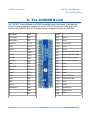
The G30HDR Board
8.2. Analog Inputs
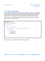
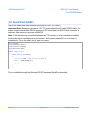
Analog inputs can read voltages from 0V to 3.3V with a 10-Bit resolution.
using System;
using Microsoft.SPOT;
using Microsoft.SPOT.Hardware;
public class Program
{
public static void Main()
{
AnalogInput ain = new AnalogInput(GHI.Pins.G30.AnalogInput.PA0);
Debug.Print("Analog Pin =" + ain.Read());
}
}
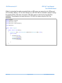
This is available through the Microsoft.SPOT.Hardware assembly.
8.3. PWM
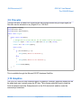
The available PWM pins have a built-in hardware to control the ration of the pin being high vs
low, duty cycle. A pin with duty cycle 0.5 will be high half the time and low the other half. This
is used to control how much energy is transferred out from a pin. An example would be to dim
an LED. With output pins, the LED can be on or off but with PWM, it can be set to 0.1 duty
cycle to give the LED only 10% of the energy.
using System;
using Microsoft.SPOT;
using Microsoft.SPOT.Hardware;
public class Program
{
public static void Main()
{
PWM LED = new PWM(GHI.Pins.G30.PwmOutput.PA0, 10000, 0.10, false);
LED.Start();
}
}
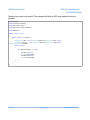
This is available through the the Microsoft.SPOT.Hardware.PWM assembly.
Another use of PWM is to generate tones. In this case, the duty cycle is typically set to 0.5 but
then the frequency will be changed as desired.
Rev. 0.01
Page 27 of 43
www.GHIElectronics.com