1
G30 SoC User Manual
Rev. 0.01
June 26, 2015
User Manual
G30 System on Chip
Document Information
Information
Description
Abstract
This document covers information about the G30 SoC,
specifications, tutorials and references.
G H I
E l e c t r o n i c s
GHI Electronics,LLC
G30 SoC User Manual
Revision History
Rev No.
Date
Rev. 0.01 8/26/14
Modification
Preliminary version.
*** This is a preliminary version ***
Rev. 0.01
Page 2 of 43
www.GHIElectronics.com
GHI Electronics,LLC
G30 SoC User Manual
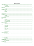
Table of Contents
Table of Contents
1.Introduction...................................................................................4
8.3.PWM..................................................................................27
1.1.G30 SoC Key Features.......................................................4
8.4.Signal Generator...............................................................28
1.2.Example Applications..........................................................4
8.5.Signal Capture...................................................................28
1.3.The .NET Micro Framework................................................5
8.6.Serial Port (UART).............................................................30
1.4.GHI Electronics and NETMF...............................................6
8.7.SPI.....................................................................................31
2.The Hardware...............................................................................7
8.8.I2C.....................................................................................32
2.1. Microcontroller....................................................................7
8.9.One-wire............................................................................33
3.Pin-Out Description.......................................................................8
8.10.Graphics..........................................................................33
3.1.Pin-out Table .......................................................................8
8.11.Accessing Files and Folders............................................34
4. G30 SoC boot up.......................................................................12
SD/MMC Memory..............................................................36
5.The GHI Boot Loader..................................................................13
8.12.Networking (TCP/IP)........................................................36
5.1.The Commands.................................................................13
8.13.USB Client (Device) ........................................................36
6.NETMF TinyCLR (firmware).......................................................14
8.14.Real Time Clock..............................................................36
6.1.Assemblies Version Matching...........................................14
8.15.Watchdog.........................................................................38
6.2.Deploying to the Emulator.................................................15
8.16.Power Control..................................................................38
6.3.Deploying to the G30 SoC.................................................16 9.Advanced use of the Microcontroller .........................................41
6.4.Targeting Different Versions of the Framework.................17
9.1.Register.............................................................................41
7.The Libraries...............................................................................19
9.2.AddressSpace...................................................................41
7.1.Finding NETMF Library Documentation............................20
9.3.Battery RAM......................................................................41
7.2.Loading Assemblies...........................................................20
9.4.EEPROM...........................................................................41
8.The G30HDR Board....................................................................22 10.design Consideration................................................................42
8.1.Digital Inputs/Outputs........................................................23 Legal Notice...................................................................................43
Interrupt Pins.....................................................................26
Licensing..................................................................................43
8.2. Analog Inputs....................................................................27
Disclaimer................................................................................43
G30 SoC
Page 3 of 43
www.ghielectronics.com
GHI Electronics,LLC
G30 SoC User Manual
Introduction
1. Introduction
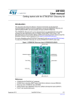
The G30 SoC is a powerful, yet low-cost, surface-mount System on Chip (SoC) running
the .NET Micro Framework software, which enables the SoC to be programmed from
Microsoft's Visual Studio, through a USB cable. Programming in a modern managed
language, such as C# and Visual Basic, allows developers to accomplish much more work in
less time by taking advantage of the extensive built-in libraries for networking, file systems,
graphical interfaces and many peripherals.
A simple two layer circuit, with just power and some connectors, can utilize the G30 SoC to
bring the latest technologies to any products. There are no additional licensing or fees and all
the development tools and SDKs are freely available.
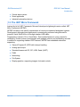
1.1. G30 SoC Key Features
●
●
●
●
●
●
●
●
●
●
●
●
●
●
●
●
●
●
.NET Micro Framework
84 MHz ARM Cortex-M4 processor
96 kB RAM
512 kB FLASH
Embedded LCD controller
46 GPIO Pins
46 Interrupt Inputs (16 at a time)
2 SPI
I2C
2 UART
16 12-Bit Analog Input
4Bit SD/MMC Memory card interface
15 PWM
112 mA max @ 25ºC
1.5 mA Hibernate Mode
-40ºC to +105ºC Operational
RoHS Lead Free
Dimensions: (16.7 mm x 16.7 mm)
●
File System (SD)
1.2. Example Applications
●
●
●
Measurement tools and testers
Networked sensors
Robotics
Rev. 0.01
Page 4 of 43
www.GHIElectronics.com
GHI Electronics,LLC
G30 SoC User Manual
Introduction
●
●
●
Central alarm system
Smart appliances
Industrial automation devices
1.3. The .NET Micro Framework
Inspired by its full .NET Framework, Microsoft developed a lightweight version called .NET
Micro Framework (NETMF).
NETMF focuses on the specific requirements of resource-constrained embedded systems.
Development, debugging and deployment is conveniently performed using Microsoft's
powerful Visual Studio tools, all through standard USB cable.
Programming is done in C# or Visual Basic. This includes libraries to cover sockets for
networking, modern memory management with garbage collector and multitasking services.
In addition to supporting standard .NET features, NETMF has embedded extensions
supporting:
●
General Purpose IO (GPIO with interrupt handling
●
Analog input/output
●
Standard buses such I2C, SPI, USB, Serial (UART)
●
PWM
●
Networking
●
File System
●
Display graphics, supporting images, fonts and controls.
Rev. 0.01
Page 5 of 43
www.GHIElectronics.com
GHI Electronics,LLC
G30 SoC User Manual
Introduction
1.4. GHI Electronics and NETMF
For years, GHI Electronics has been the lead Microsoft partner on .NET Micro Framework
(NETMF). The core NETMF was also extended with new exclusive libraries for an additional
functionality, such as USB Host.
One of the important extensions by GHI Electronics is Runtime Loadable Procedures (RLP),
allowing native code (Assembly/C) to be compiled and loaded right from withing managed
code (C#/Visual Basic) to handle time critical and processor intensive tasks. IT can also be
used to add new native extensions to the system.
As for networking, WiFi and PPP libraries are added by GHI Electronics to the NETMF core.
Combined with Ethernet and the other managed services, it is a complete toolbox for the
internet of things.
All the mentioned features are loaded and tested on the G30 SoC. GHI Electronics
continuously maintains, upgrades and solves any of the issues on the G30 SoC firmware, to
provide regular and free releases. Users can simply load the new software on the G30 SoC
using USB or Serial, and even use the in-field-update feature. This feature allows the upgrade
to be done through any of the available interface, including file system and networking.
Rev. 0.01
Page 6 of 43
www.GHIElectronics.com
GHI Electronics,LLC
G30 SoC User Manual
The Hardware
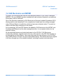
2. The Hardware
The G30 SoC core components includes the processor, 512kB flash, and 96KB RAM.
The small, 38.1 x 26.7 x 3.55 mm (only 1 x 1.5 inches), module contains everything needed to
run a complex embedded-system in a cost-effective and flexible solution. All that is needed is
a 3.3V power source and some connections to take advantage of the G30 SoC's long list of
available features.
2.1. Microcontroller
The microcontroller is the heart of G30 SoC. Running at 180Mhz, 32Bit, Cortex-M4 and
includes a long list of available peripherals. The NETMF core libraries, combined with the GHI
Electronics extensions, provide a long list of methods to access the available peripherals.
Rev. 0.01
Page 7 of 43
www.GHIElectronics.com
GHI Electronics,LLC
G30 SoC User Manual
Pin-Out Description
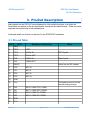
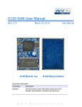
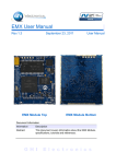
3. Pin-Out Description
Many signals on the G30 SoC are multiplexed to offer multiple functions on a single pin.
Developers can decide on the pin functionality through the provided libraries. These are some
important facts pertaining to the available pins:
Advanced details on all pins can be found in the STM32F401 datasheet.
3.1. Pin-out Table
G30
GPIO
Multiplexed Function(s)
1
VBAT
2
PC13
LDR1
3
PC14
32 KHz IN
4
PC15
32 kHz OUT
5
PH0
12MHz IN
6
PH1
12MHz OUT
7
RESET
8
PC0
ADC10
9
PC1
ADC11
10
PC2
ADC12
11
PC3
ADC13
12
GND
13
3.3V
14
PA0
ADC0, COM2 CTS, PWM3
15
PA1
ADC1, COM2 RTS, PWM4
16
PA2
ADC2, COM2 TX, PWM5
17
PA3
ADC3, COM2 RX, PWM6
18
GND
19
3.3V
Rev. 0.01
Notes
RTC Crystal
Main Crystal
Active low, not 5V tolerant.
This power source is for the
internal analog circuitry.
Page 8 of 43
www.GHIElectronics.com
GHI Electronics,LLC
G30 SoC User Manual
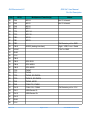
Pin-Out Description
G30
GPIO
Multiplexed Function(s)
Notes
20
PA4
ADC4
Not 5V tolerant.
21
PA5
ADC5
Not 5V tolerant.
22
PA6
ADC6
23
PA7
ADC7
24
PC4
ADC14
25
PC5
ADC15
26
PB0
ADC8
27
PB1
ADC9
28
PB2
29
PB10
30
VCAP
31
GND
32
3.3V
33
PB12
34
PB13
SPI2 SCK
35
PB14
SPI2 MISO
36
PB15
SPI2 MOSI
37
PC6
PWM7
38
PC7
PWM8
39
PC8
PWM9, SD DATA0
40
PC9
PWM10, SD DATA1
41
PA8
PWM0, MCO1
42
PA9
COM1 TX, PWM1
43
PA10
COM1 RX, PWM2
44
PA11
USB Device D-
45
PA12
USB Device D+
46
PA13
47
GND
48
3.3V
Rev. 0.01
10k Resistor pull to GND
MODE (debug interface)
High = USB, Low = Serial
2.2uF to GND
Page 9 of 43
10k Resistor pull to 3.3V
www.GHIElectronics.com
GHI Electronics,LLC
G30 SoC User Manual
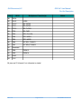
Pin-Out Description
G30
GPIO
Multiplexed Function(s)
49
PA14
50
PA15
LDR0
51
PC10
SD DATA2
52
PC11
SD DATA3
53
PC12
SD CLOCK
54
PD2
SD CMD
55
PB3
SPI1 CLOCK
56
PB4
SPI1 MISO
57
PB5
SPI1 MOSI
58
PB6
I2C SCL, PWM11
59
PB7
I2C SDA, PWM12
60
Reserved
61
PB8
PWM13
62
PB9
PWM14
63
GND
64
3.3V
Notes
All pins are 5V tolerant if not otherwise is stated.
Rev. 0.01
Page 10 of 43
www.GHIElectronics.com
GHI Electronics,LLC
G30 SoC User Manual
Pin-Out Description
Rev. 0.01
Page 11 of 43
www.GHIElectronics.com
GHI Electronics,LLC
G30 SoC User Manual
G30 SoC boot up
4. G30 SoC Boot Up
To be added.
Rev. 0.01
Page 12 of 43
www.GHIElectronics.com
GHI Electronics,LLC
G30 SoC User Manual
The GHI Boot Loader
5. The GHI Boot Loader
The GHI Boot Loader software is pre-loaded and locked on the G30 SoC. It is used to update
the firmware and can be used to do a complete erase all flash memory. The GHI boot loader
is rarely needed but it is recommended to keep access available in all project designs.
The GHI boot loader accepts simple commands sent with the help of a terminal service
software, such as TeraTerm or Hyper Terminal. A command character is sent and the boot
loader performs an action; results are returned in a human friendly format followed by a "BL"
indicating that the boot loader is ready for the next command. All commands and responses
use ASCII encoded characters.
The G30 SoC boot up section provides the required information on how to choose the access
interface and how to access the GHI boot loader.
5.1. The Commands
Command
Description
Notes
V
Returns the GHI Loader
version number.
Format X.XX
e.g. 1.06
E
Erases the Flash memory Confirm erase by sending Y or any other character to abort.
This command erases TinyBooter, the G30 SoC firmware and the
user's application.
X
Loads the new
TinyBooter file
Error: Reference source not found section explains this command
process in more detail.
R
Runs firmware.
Exits the GHI boot loader mode and runs TinyBooter.
B
Changes the baud rate to User needs to change the baud rate on the terminal service
921600
accordingly. Available on serial access interface only.
Notes:
●
●
Commands are not followed by pressing the “ENTER” key. The single command letter is sent to the G30
SoC; which immediately begins executing the command.
The Boot loader commands are case sensitive.
… To be completed!
Rev. 0.01
Page 13 of 43
www.GHIElectronics.com
GHI Electronics,LLC
G30 SoC User Manual
NETMF TinyCLR (firmware)
6. NETMF TinyCLR (firmware)
The Firmware is the main piece of embedded software running on the G30 SoC. It is what
interprets and runs the user's managed application and it is what Microsoft's Visual Studio
use to deploy, hook-into and debug the managed application. As explained in Error:
Reference source not found section, hardware interfaces between TinyCLR and the host
development system is either USB or Serial. In this chapter the examples use the USB
interface.
If necessary, the module's firmware can be updated as described in the Error: Reference
source not found chapter.
6.1. Assemblies Version Matching
The firmware includes extensions added by GHI Electronics. These extensions are often
improved and further extended. If the managed application (C# or Visual Basic) uses any of
the GHI specific extensions, care must be taken when a new SDK is installed.
This is due to the fact that the existing Visual Studio projects will include a local copy of the
assemblies supplied by the old SDK; during compilation of the application, the extensions
may not match what is found.
Additionally, the assemblies themselves are compiled for use with specific SDK versions.
For example where an application was previously compiled with 4.2, then the 4.3 SDK is
installed; even if a successful compilation occurs (no extension conflicts were found), then the
deployment process will begin to load 4.2 assemblies; this will cause loading errors when
compiling for 4.3. This will not harm the G30 SoC. Visual Studio's Output panel will contain
something like:
there is further discussions of assemblies in the Loading Assemblies section of chapter 7.
Rev. 0.01
Page 14 of 43
www.GHIElectronics.com
GHI Electronics,LLC
G30 SoC User Manual
NETMF TinyCLR (firmware)
6.2. Deploying to the Emulator
Once the latest SDK is installed and the G30 SoC is loaded with the latest TinyBooter and
NETMF TinyCLR, using Visual Studio to load/debug C# and Visual Basic application is very
easy. If not installed yet, the latest SDK should be downloaded and installed on the
development machine. The following link points to a page on the GHI Electronics website that
shows what software components are necessary to install along with the latest SDK
www.ghielectronics.com/support/netmf
When done, Visual Studio can be started to create a new Micro Framework project Console
Application.
C# is selected in this example but Visual Basic will be very similar. Run the code as is by
pressing F5 or clicking the start button. This should open up the emulator and run the
program. This program prints “Hello World” on the output window, not on the screen. If the
output window is not visible, it can be opened from the “VIEW” top menu. When running the
emulator has a pre-developed device that appears. The program closes when done causing
the emulator device to close. The output window of Visual Studio should be full of messages...
from loading assemblies (libraries) on power up to loading the application, to the actual “Hello
Rev. 0.01
Page 15 of 43
www.GHIElectronics.com
GHI Electronics,LLC
G30 SoC User Manual
NETMF TinyCLR (firmware)
World!.”
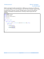
Now view open the program that was created automatically, Program.cs:
Change the program to the following.
using System;
using Microsoft.SPOT;
public class Program
{
public static void Main()
{
Debug.Print("* Amazing! *");
}
}
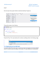
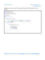
Press the F5 key. The output window will now show something similar to the following image.
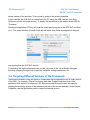
6.3. Deploying to the G30 SoC
This section relies on the work done in the previous section as loading to the actual hardware
device is exactly the same as loading to the emulator. The only difference is in selecting the
Rev. 0.01
Page 16 of 43
www.GHIElectronics.com
GHI Electronics,LLC
G30 SoC User Manual
NETMF TinyCLR (firmware)
device instead of the emulator. This is done by going to the project properties:
In this example, the G30 SoC is connected to the PC using the USB interface (see Error:
Reference source not found section). To deploy the application to the module select USB for
“Transport.”
Running the application (F5 key) will load the exact same program on the G30 SoC and then
run it. The output window of Visual Studio will still show very similar messages but they are
now coming from the G30 SoC directly.
If necessary, the deployed program can use the full power of the Visual Studio debugger;
including, stepping through lines, inspecting variables, setting breakpoints, etc.
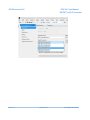
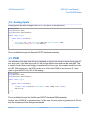
6.4. Targeting Different Versions of the Framework
There are times when it may be useful to compile and deploy applications for an older version
of the SDK. For example, if there is a module with older firmware and there is an older
application that needs to be deployed. GHI Electronics and Microsoft makes this easy by
shipping the previous version of the framework as part of the current package. Under Project
Properties, use the Application panel to target the desired version:
Rev. 0.01
Page 17 of 43
www.GHIElectronics.com
GHI Electronics,LLC
G30 SoC User Manual
NETMF TinyCLR (firmware)
Rev. 0.01
Page 18 of 43
www.GHIElectronics.com
GHI Electronics,LLC
G30 SoC User Manual
The Libraries
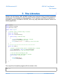
7. The Libraries
Similar to the full desktop .NET, NETMF includes many services to help in modern application
development. One example would be threading. This is typically very difficult to deal with on
embedded systems, but thanks to NETMF, this is very easy and works as well as it does on a
desktop application.
using System;
using System.Threading;
using Microsoft.SPOT;
public class Program
{
// We will print a counter every 1 second
static int Count=0;
static void CounterThread()
{
while (true)// Infinite loop
{
Thread.Sleep(1000);// Wait for 1 second
Count++;// Increment the count
Debug.Print("Count = " + Count);// Print the count
}
}
// ************************************************
static void Main()
{
//Create a second thread, main is automatically a thread
Thread EasyThread = new Thread(CounterThread);
EasyThread.Start();// Run the Counter Thread
// We can now do anything we like
// We will print Hi once every 2 seconds
while (true)// Infinite loop
{
Debug.Print("Hi");
Thread.Sleep(2000);
}
}
}
The output from the earlier program will look similar to this:
Hi
Count = 1
Hi
Rev. 0.01
Page 19 of 43
www.GHIElectronics.com
GHI Electronics,LLC
G30 SoC User Manual
The Libraries
Count
Count
Hi
Count
Count
Hi
Count
= 2
= 3
= 4
= 5
= 6
7.1. Finding NETMF Library Documentation
While this user manual is not meant to be a tutorial on the use of NETMF, a lot of details are
provided to aid newcomers to NETMF. For further details, see the documentation library on
the GHI website. Also, the main support page for NETMF includes links to the library
reference documentation (NETMF APIs).
Because NETMF is a subset of the full .NET platform, services such as file input/output and
Networking are very close, sometimes identical, between the full .NET Framework and the
smaller .NET Micro Framework. The internet is a great source of .NET examples code that
often can be used in a NETMF program with no changes!
7.2. Loading Assemblies
In an earlier example, the threading libraries were used. This was done by identifying the
namespace via the statement:
using System.Threading;
The compiled code for classes in the Threading library are part of the mscorlib assembly
(DLL).
Rev. 0.01
Page 20 of 43
www.GHIElectronics.com
GHI Electronics,LLC
G30 SoC User Manual
The Libraries
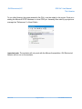
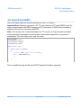
To use other libraries, the proper assembly file (DLL) must be added to the project. Such as in
adding the Microsoft.SPOT.Hardware to use a GPIO pin. Assembly files used by a project are
managed as “References” in Visual Studio:
Important note: The emulator will only work with the Microsoft assemblies. GHI Electronics'
libraries will not run on the emulator.
Rev. 0.01
Page 21 of 43
www.GHIElectronics.com
GHI Electronics,LLC
G30 SoC User Manual
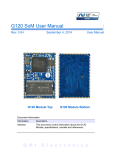
The G30HDR Board
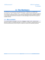
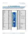
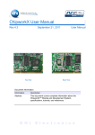
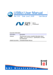
8. The G30HDR Board
The G30 SoC is also available in a DIP42-compatible trough hole format. It includes the
requires crystal and passive components for the G30 SoC to operate. A USB port is also
found on the G30HDR. Only a 3.3V power source is needed to operate the G30HDR.
SPI1 MOSI
PB5
REST
SCL/PWM11
PB6
PC0
ADC10
SDA/PWM12
PB7
PC1
ADC11
OSC32 IN
PC14
PC15
OSC32 OUT
LDR1
PC13
PC2
ADC12
PWM13
PB8
PC3
ADC13
VBAT
PA0
ADC0/COM2 CTS/PWM3
SD CLK
PC12
PA1
ADC1/COM2 RTS/PWM4
SD CMD
PD2
PA2
ADC2/COM2 TX/PWM5
SPI1 CLK
PB3
PA3
ADC3/COM2 RX/PWM6
ADC8
PB0
PA4
ADC4
SPI1 MISO
PB4
PA5
ADC5
SD D3
PC11
PB0
ADC8
SD D2
PC10
PB10
MODE
LDR0
PA15
PA9
COM1 TX/PWM1
ADC6
PA6
PA10
COM2 RX/PWM2
ADC7
PA7
PC6
PWM7
ADC14
PC4
PC7
PWM8
PWM0/MCO1
PA8
PC8
PWM9/SD D0
GND
PC9
PWM10/SD D1
3V3
USB
VBUS
Rev. 0.01
Page 22 of 43
www.GHIElectronics.com
GHI Electronics,LLC
G30 SoC User Manual
The G30HDR Board
8.1. Digital Inputs/Outputs
GPIO (General Purpose Input Output) are used to set a specific pin high or low states when
the pin is used as an output. On the other hand, when the pin is an input, the pin can be used
to detect a high or low state on the pin. High means there is voltage on the pin, which is
referred to as “true” in programming. Low means there is no voltage on the pin, which is
referred to as “false”. Pins can also be enabled with an internal weak pull-up or pull-down
resistor. Here is a blink LED example.
using System;
using System.Threading;
using Microsoft.SPOT.Hardware;
public class Program
{
public static void Main()
{
OutputPort LED = new OutputPort(Cpu.Pin.GPIO_Pin0, true);
while (true)
{
LED.Write(true);
Thread.Sleep(500);
LED.Write(false);
Thread.Sleep(500);
}
}
}
This is available through the Microsoft.SPOT.Hardware assembly.
Rev. 0.01
Page 23 of 43
www.GHIElectronics.com
GHI Electronics,LLC
G30 SoC User Manual
The G30HDR Board
While it is clear that the earlier example blinks an LED every one second (on for 500ms and
off for another 500ms), it is not clear what pin on G30 SoC will be controlled. Instead of using
the generic GPIO_Pin0 name, the actual G30 SoC name can be found in the GHI.Pins
assembly. This example now uses the actual G30 SoC pin name using the GHI.Pins
assembly.
using
using
using
using
System;
System.Threading;
Microsoft.SPOT;
Microsoft.SPOT.Hardware;
using GHI.Pins;
public class Program
{
public static void Main()
{
OutputPort LED = new OutputPort(GHI.Pins.G30.Gpio.PA0, true);
while (true)
{
LED.Write(true);
Thread.Sleep(500);
LED.Write(false);
Thread.Sleep(500);
}
}
}
Rev. 0.01
Page 24 of 43
www.GHIElectronics.com
GHI Electronics,LLC
G30 SoC User Manual
The G30HDR Board
Reading Input pins is as simple! This example will blink an LED only when the button is
pressed.
using
using
using
using
System;
System.Threading;
Microsoft.SPOT;
Microsoft.SPOT.Hardware;
using GHI.Pins;
public class Program
{
public static void Main()
{
OutputPort LED = new OutputPort(GHI.Pins.G30.Gpio.PA0, true);
InputPort Button = new InputPort(GHI.Pins.G30.Gpio.PA1,false,
Port.ResistorMode.PullUp);
while (true)
{
if (Button.Read() == true)
{
LED.Write(true);
Thread.Sleep(500);
LED.Write(false);
Thread.Sleep(500);
}
}
}
}
Rev. 0.01
Page 25 of 43
www.GHIElectronics.com
GHI Electronics,LLC
G30 SoC User Manual
The G30HDR Board
Interrupt Pins
The beauty of modern and managed language shines with the use of events and threading.
This example will set a pin high when a button is pressed. It should be noted here that the
system in this example spends most its time a in a lower power state.
Note: Only pins on port 0 and port 2 are interrupt capable.
using
using
using
using
System;
System.Threading;
Microsoft.SPOT;
Microsoft.SPOT.Hardware;
using GHI.Pins;
public class Program
{
public static OutputPort LED = new OutputPort(GHI.Pins.G30.Gpio.PA0, true);
public static void Main()
{
InterruptPort Button = new InterruptPort(GHI.Pins.G30.Gpio.PA1,true,
Port.ResistorMode.PullUp,
Port.InterruptMode.InterruptEdgeBoth);
Button.OnInterrupt += Button_OnInterrupt;
// The system can do anything here, even sleep!
Thread.Sleep(Timeout.Infinite);
}
static void Button_OnInterrupt(uint port, uint state, DateTime time)
{
LED.Write(state > 0);
}
}
Rev. 0.01
Page 26 of 43
www.GHIElectronics.com
GHI Electronics,LLC
G30 SoC User Manual
The G30HDR Board
8.2. Analog Inputs
Analog inputs can read voltages from 0V to 3.3V with a 10-Bit resolution.
using System;
using Microsoft.SPOT;
using Microsoft.SPOT.Hardware;
public class Program
{
public static void Main()
{
AnalogInput ain = new AnalogInput(GHI.Pins.G30.AnalogInput.PA0);
Debug.Print("Analog Pin =" + ain.Read());
}
}
This is available through the Microsoft.SPOT.Hardware assembly.
8.3. PWM
The available PWM pins have a built-in hardware to control the ration of the pin being high vs
low, duty cycle. A pin with duty cycle 0.5 will be high half the time and low the other half. This
is used to control how much energy is transferred out from a pin. An example would be to dim
an LED. With output pins, the LED can be on or off but with PWM, it can be set to 0.1 duty
cycle to give the LED only 10% of the energy.
using System;
using Microsoft.SPOT;
using Microsoft.SPOT.Hardware;
public class Program
{
public static void Main()
{
PWM LED = new PWM(GHI.Pins.G30.PwmOutput.PA0, 10000, 0.10, false);
LED.Start();
}
}
This is available through the the Microsoft.SPOT.Hardware.PWM assembly.
Another use of PWM is to generate tones. In this case, the duty cycle is typically set to 0.5 but
then the frequency will be changed as desired.
Rev. 0.01
Page 27 of 43
www.GHIElectronics.com
GHI Electronics,LLC
G30 SoC User Manual
The G30HDR Board
In the case of servo motor control, or when there is a need to generate a pulse at a very
specific timing, PWM provides a way to set the high and low pulse with.
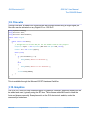
8.4. Signal Generator
Using Signal Generator, developers can produce different waveforms. This is available on any
digital output pin.
using
using
using
using
using
System;
System.Threading;
Microsoft.SPOT;
GHI.Pins;
GHI.IO;
public class Program
{
public static void Main()
{
uint[] signal = new uint[4] {1000,2000,3000,4000};
SignalGenerator pin = new SignalGenerator(GHI.Pins.G30.Gpio.PA0, false);
pin.Set(false, signal);
Thread.Sleep(Timeout.Infinite);
}
}
While handeled in software, the SignalGenerator runs through internal interrupts in the
background and so is not blocking to the system. Another Blocking methd is also provided for
higher accuracy. For example, the blocking method can generate acarrier frequency. This is
very useful for infrared remote control applications.
This is available through the GHI.Hardware assembly.
8.5. Signal Capture
Signal Capture monitors a pin and records any changes of the pin into an array. The recorded
values are the times taken between each signal change.
using
using
using
using
using
using
System;
System.Threading;
Microsoft.SPOT;
Microsoft.SPOT.Hardware;
GHI.Pins;
GHI.IO;
Rev. 0.01
Page 28 of 43
www.GHIElectronics.com
GHI Electronics,LLC
G30 SoC User Manual
The G30HDR Board
public class Program
{
public static void Main()
{
uint[] signal = new uint[100];
SignalCapture pin = new
SignalCapture(GHI.Pins.G30.Gpio.PA0,Port.ResistorMode.Disabled);
pin.Read(false, signal);
}
Thread.Sleep(Timeout.Infinite);
}
This is available through the GHI.Hardware assembly.
Rev. 0.01
Page 29 of 43
www.GHIElectronics.com
GHI Electronics,LLC
G30 SoC User Manual
The G30HDR Board
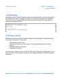
8.6. Serial Port (UART)
One of the oldest and most common protocols is UART (or USART).
Important Note: Serial port pins have 3.3V TTL levels where the PC uses RS232 levels. For
proper communication with RS232 serial ports (PC serial port), an RS232 level converter is
required. One common converter is MAX232.
Note: If the serial port is connected between two TTL circuits, no level converter is needed
but they should be connected as a null modem. Null modem means RX on one circuit is
connected to TX on the other circuit, and vice versa.
using
using
using
using
System;
System.IO.Ports;
System.Threading;
Microsoft.SPOT;
public class Program
{
public static void Main()
{
SerialPort COM1 = new SerialPort("COM1");
int c = COM1.ReadByte();
// ...
}
}
This is available through the Microsoft.SPOT.Hardware.SerialPort assembly.
Rev. 0.01
Page 30 of 43
www.GHIElectronics.com
GHI Electronics,LLC
G30 SoC User Manual
The G30HDR Board
8.7. SPI
G30 SoC supports two SPI interfaces, SPI1 and SPI2. SPI Bus is designed to interface with
multiple SPI slave devices, the active slave is selected by asserting the Chip Select line on
the relative slave device.
using System.Threading;
using Microsoft.SPOT.Hardware;
public class Program
{
public static void Main()
{
SPI.Configuration MyConfig =
new SPI.Configuration(Cpu.Pin.GPIO_Pin1,
false, 0, 0, false, true, 1000, SPI.SPI_module.SPI1);
SPI MySPI = new SPI(MyConfig);
byte[] tx_data = new byte[10];
byte[] rx_data = new byte[10];
MySPI.WriteRead(tx_data, rx_data);
}
Thread.Sleep(Timeout.Infinite);
}
This is available through the Microsoft.SPOT.Hardware assembly.
Rev. 0.01
Page 31 of 43
www.GHIElectronics.com
GHI Electronics,LLC
G30 SoC User Manual
The G30HDR Board
8.8. I2C
I2C is a two-wire addressable serial interface.
The G30 SoC supports one master I2C port.
// Setup the I2C bus
I2CDevice.Configuration con =
new I2CDevice.Configuration(0x38, 400);
I2CDevice MyI2C = new I2CDevice(con);
// Start a transaction
I2CDevice.I2CTransaction[] xActions =
new I2CDevice.I2CTransaction[2];
byte[] RegisterNum = new byte[1] { 2 };
xActions[0] = I2CDevice.CreateWriteTransaction(RegisterNum);
This is available through the Microsoft.SPOT.Hardware assembly.
Rev. 0.01
Page 32 of 43
www.GHIElectronics.com
GHI Electronics,LLC
G30 SoC User Manual
The G30HDR Board
8.9. One-wire
Through one-wire, a master can communicate with multiple slaves using a single digital pin.
One-wire can be activated on any Digital I/O on G30 SoC.
using System.Threading;
using Microsoft.SPOT;
using Microsoft.SPOT.Hardware;
public class Program
{
public static void Main()
{
// Change this to correct GPI pin for the onewire used in the project!
OutputPort myPin = new OutputPort(GHI.Pins.G30.Gpio.PA0, false);
OneWire ow = new OneWire(myPin);
while (true)
{
if (ow.TouchReset() > 0)
{
Debug.Print("Device is detected.");
}
else
{
Debug.Print("Device is not detected.");
}
Thread.Sleep(10000);
}
}
}
This is available through the Microsoft.SPOT.Hardware.OneWire.
8.10. Graphics
The G30 SoC does not have internal support for graphics/ However, graphical display can still
be added and used, typically using the SPI bus. The software added will need to draw the
fonts and shapes manually. Examples exist on the GHI electronics' website, under the
community's codeshare.
Rev. 0.01
Page 33 of 43
www.GHIElectronics.com
GHI Electronics,LLC
G30 SoC User Manual
The G30HDR Board
8.11. Accessing Files and Folders
The File System feature in NETMF is near very similar to the full .NET and can be tested from
within the Microsoft NETMF emulator with minor changes. Changes include removing any of
the GHI library dependencies. There are no limits on file sizes and counts, beside the limits of
the FAT file system itself. NETMF supports FAT16 and FAT32. Files are made accessible on
SD cards.
Most online examples on how to use .NET to access files on PCs can be used to read and
write files on the G30 SoC. The GHI Electronics' online documentation has further
examples as well.
This is available through the GHI.Hardware, System.IO and Microsoft.SPOT.IO.
Rev. 0.01
Page 34 of 43
www.GHIElectronics.com
GHI Electronics,LLC
G30 SoC User Manual
The G30HDR Board
using
using
using
using
System;
System.IO;
Microsoft.SPOT;
Microsoft.SPOT.IO;
using GHI.IO.Storage;
class Program
{
public static void Main()
{
// ...
// SD Card is inserted
// Create a new storage device
SD sdPS = new SDCard();
// Mount the file system
sdPS.Mount();
// Assume one storage device is available, access it through
// NETMF and display the available files and folders:
Debug.Print("Getting files and folders:");
if (VolumeInfo.GetVolumes()[0].IsFormatted)
{
string rootDirectory =
VolumeInfo.GetVolumes()[0].RootDirectory;
string[] files = Directory.GetFiles(rootDirectory);
string[] folders = Directory.GetDirectories(rootDirectory);
Debug.Print("Files available on " + rootDirectory + ":");
for (int i = 0; i < files.Length; i++)
Debug.Print(files[i]);
Debug.Print("Folders available on " + rootDirectory + ":");
for (int i = 0; i < folders.Length; i++)
Debug.Print(folders[i]);
}
else
{
Debug.Print("Storage is not formatted. " +
"Format on PC with FAT32/FAT16 first!");
}
// Unmount when done
sdPS.Unmount();
}
}
Rev. 0.01
Page 35 of 43
www.GHIElectronics.com
GHI Electronics,LLC
G30 SoC User Manual
The G30HDR Board
SD/MMC Memory
SD and MMC memory cards have similar interfaces. G30 SoC supports both cards and also
supports SDHC/SDXC cards. The interface runs through a true 4-bit SD interface. SD cards
are available in different sizes but they are all of an identical function making them all
supported on the G30 SoC.
8.12. Networking (TCP/IP)
There is no built in networking support for networking; however, there are many low-cost
network interface devices that can be controlled using UART or SPI to give G30 SoC a
networking option. An example is Wiznet's Ethernet chipsets.
8.13. USB Client (Device)
To be added.
8.14. Real Time Clock
The G30 SoC processor includes a real-time clock (RTC) that can operate while the
processor is off, through a backup battery or a super capacitor. An appropriate 32.768KHz
crystal must also be added to the system. All details about power and required crystal can be
found in the STM32F401 datasheet and user manual.
Rev. 0.01
Page 36 of 43
www.GHIElectronics.com
GHI Electronics,LLC
G30 SoC User Manual
The G30HDR Board
NETMF has its own time keeping that is independent from the real time clock. If actual time is
need, the software should read the RTC and set the system's time.
using System;
using GHI.Processor;
using Microsoft.SPOT;
public class Program
{
public static void Main()
{
DateTime DT;
try
{
DT = RealTimeClock.GetDateTime();
Debug.Print("Current Real-time Clock " + DT.ToString());
}
catch
{
// If the time is not good due to powerloss
// an exception will be thrown and a new time will need to be set
Debug.Print("The date was bad and caused a bad time");
// This will set a time for the Real-time Clock clock to 1:01:01 on 1/1/2012
DT = new DateTime(2012, 1, 1, 1, 1, 1);
RealTimeClock.SetDateTime(DT);
}
if (DT.Year < 2011)
{
Debug.Print("Time is not resonable");
}
}
Debug.Print("Current Real-time Clock " + RealTimeClock.GetDateTime().ToString());
// This will set the clock to 9:30:00 on 9/15/2011
DT = new DateTime(2011, 9, 15, 7, 30, 0);
RealTimeClock.SetDateTime(DT);
Debug.Print("New Real-time Clock " + RealTimeClock.GetDateTime().ToString());
}
Tip: The system time can also be set using time services through the internet.
Rev. 0.01
Page 37 of 43
www.GHIElectronics.com
GHI Electronics,LLC
G30 SoC User Manual
The G30HDR Board
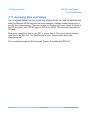
8.15. Watchdog
Watchdog is used to reset the system if it enters an erroneous state. The error can be due to
internal fault or the user's managed code. When the Watchdog is enabled with a specified
timeout, the user must keep resetting the Watchdog counter within this timeout interval or
otherwise the system will reset.
// Enable with 10 second timeout
GHI.Processor.Watchdog.Enable(10 * 1000);
while (true)
{
// Do some work
GHI.Processor.Watchdog.ResetCounter();
}
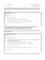
8.16. Power Control
Embedded devices often must limit power usage as much as possible. Devices may lower
their power consumption in many ways:
1.Reduce the processor clock
2.Shutdown the processor when system is idle (keep peripherals and interrupts
running)
3.Shutdown specific peripherals
4.Hibernate the system
A common way to wake a device is using the RTC alarm. Whenever the alarm goes off, it will
wake the device. These examples require the GHI.Hardware and Microsoft.SPOT.Hardware
assemblies.
Rev. 0.01
Page 38 of 43
www.GHIElectronics.com
GHI Electronics,LLC
G30 SoC User Manual
The G30HDR Board
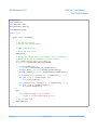
Use Microsoft.SPOT.Hardware.HardwareEvent.OEMReserved2 for RTC alarm. When the
program starts, it will set an RTC alarm for 30 seconds in the future and then hibernate until
then.
using GHI.Processor;
using Microsoft.SPOT.Hardware;
using System;
public class Program
{
public static void Main()
{
RealTimeClock.SetAlarm(DateTime.Now.AddSeconds(30));
PowerState.Sleep(SleepLevel.DeepSleep, HardwareEvent.OEMReserved2);
///Continue on with your program here
}
}
The device will awaken whenever an interrupt port is triggered. Some devices can use
interrupts internally that can cause spurious wakeups if not disabled. Use
Microsoft.SPOT.Hardware.HardwareEvent.OEMReserved1 for interrupts.
NETMF's interrupt ports only function when their glitch filter is enabled or they have an event
handler subscribed.
using Microsoft.SPOT.Hardware;
using System;
public class Program
{
public static void Main()
{
var interrupt = new InterruptPort(Cpu.Pin.GPIO_Pin0, true, Port.ResistorMode.PullUp,
Port.InterruptMode.InterruptEdgeHigh);
interrupt.OnInterrupt += interrupt_OnInterrupt;
PowerState.Sleep(SleepLevel.DeepSleep, HardwareEvent.OEMReserved1);
///Continue on with your program here
}
private static void interrupt_OnInterrupt(uint data1, uint data2, DateTime time)
{
//Interrupted
}
}
Rev. 0.01
Page 39 of 43
www.GHIElectronics.com
GHI Electronics,LLC
G30 SoC User Manual
The G30HDR Board
Rev. 0.01
Page 40 of 43
www.GHIElectronics.com
GHI Electronics,LLC
G30 SoC User Manual
Advanced use of the Microcontroller
9. Advanced Use Of The Microcontroller
The G30 SoC is based on the STM32F4021 microcontroller. There are times when direct
programming is needed. GHI has extended NETMF to allow assembly level access from
managed code to the microcontroller.
All these examples use the GHI.Hardware assembly.
9.1. Register
This class is used for manipulating the processor registers directly.
To be completed.
var EMCCLKSEL = new GHI.Processor.Register(0x400FC100);
EMCCLKSEL.ClearBits(1 << 0); // OVERDRIVE
//EMCCLKSEL.SetBits(1 << 0);
// NORMAL
9.2. AddressSpace
Allows applications to read and write memory directly. This code reads a byte from address
0xA0000000.
GHI.Processor.AddressSpace.Read(0xA0000000);
9.3. Battery RAM
To be added.
9.4. EEPROM
To be added.
Rev. 0.01
Page 41 of 43
www.GHIElectronics.com
GHI Electronics,LLC
G30 SoC User Manual
design Consideration
10. Design Consideration
To be added.
Rev. 0.01
Page 42 of 43
www.GHIElectronics.com
GHI Electronics,LLC
G30 SoC User Manual
Legal Notice
Legal Notice
Licensing
The G30 SoC, with all its built in software components, is licensed for commercial and noncommercial use. No additional fee or licensing is required.
Disclaimer
IN NO EVENT SHALL GHI ELECTRONICS, LLC. OR ITS CONTRIBUTORS BE LIABLE FOR ANY
DIRECT, INDIRECT, INCIDENTAL, SPECIAL, EXEMPLARY, OR CONSEQUENTIAL DAMAGES
(INCLUDING, BUT NOT LIMITED TO, PROCUREMENT OF SUBSTITUTE GOODS OR SERVICES; LOSS
OF USE, DATA, OR PROFITS; OR BUSINESS INTERRUPTION) HOWEVER CAUSED AND ON ANY
THEORY OF LIABILITY, WHETHER IN CONTRACT, STRICT LIABILITY, OR TORT (INCLUDING
NEGLIGENCE OR OTHERWISE) ARISING IN ANY WAY OUT OF THE USE OF THIS PRODUCT, EVEN
IF ADVISED OF THE POSSIBILITY OF SUCH DAMAGE. SPECIFICATIONS ARE SUBJECT TO CHANGE
WITHOUT ANY NOTICE. GHI ELECTRONICS, LLC LINE OF PRODUCTS ARE NOT DESIGNED FOR
LIFE SUPPORT APPLICATIONS.
G30 is a Trademark of GHI Electronics, LLC
.NET Micro Framework, Visual Studio, MFDeploy, and Windows are registered or
unregistered trademarks of Microsoft Corporation.
Other Trademarks and Registered Trademarks are Owned by their Respective Companies.
Rev. 0.01
Page 43 of 43
www.GHIElectronics.com