1
An Integrated, Modular Simulation
System for Education and Research
A Thesis
Presented to
the faculty of
California State Polytechnic State University
In partial fulfillment
of the requirements for the degree of
Master of Science in Aeronautical Engineeering
By:
Douglas K. Hiranaka
1999
Authorization Page
I grant permission for the reproduction of this thesis in its entirety or any of its parts, without further
authorization from me.
________________________
Signature
________________________
Date
ii
Approval Page
TITLE: An Integrated, Modular Simulation System for Education and Research
AUTHOR: Douglas K Hiranaka
DATE SUBMITTED: May 10, 1999
Dr. Daniel J Biezad
_____________________________
_____________________________
Advisor
Signature
Dr. Jin Tso
_____________________________
_____________________________
Committee Member
Signature
Dr. Jordi Puig-suari
_____________________________
_____________________________
Committee Member
Signature
Mohammadreza H. Mansur
_____________________________
_____________________________
Committee Member
Signature
iii
Abstract
An Integrated, Modular Simulation
System for Education and Research
Douglas Hiranaka
Simulation is the most powerful learning and research tool in engineering.
However, simulation of aircraft has only been available to students with advanced
preparation in aircraft dynamics and programming skills. This paper describes the
development and evolution of a low cost flight simulation lab into a modular, powerful,
flexible, easy to use and accurate flight modeling system.
With the advent of cheap, fast personal computers and powerful software
packages flight simulation can be available to all levels of flight dynamics analysts.
Input/output (I/O) hardware has matured and evolved from expensive specialty items to
mass produced consumer products, and the equations of motion for a standard
configuration aircraft are well understood. The Cal Poly simulation lab has computers,
equations of motion, a simulation cab, desktop input inceptors, and CAD design packages
to analyze and design aircraft and control systems. Individual components don t make up
a simulator any more than a stack of chips make up a computer.
After creating several tools to add to the basic simulator, a sophisticated and
flexible system was developed that could be used by engineers and students with almost
any level of preparation. Simulink, along with Real Time Workshop, provide a flexible
and powerful environment that separate the hardware drivers and simulation software
into individual functions and allow the components to be assembled in any combination.
The system was verified by creating simulations using several verified models and
comparing output from the Simulink model with the output from Real Time Workshop.
iv
Acknowledgements
The author of this paper would like to thank all of the contributors to the Pangloss and
PhEagle projects, especially Fritz Anderson for the contributions that allowed this work in
progress to commence. I would also like to thank Eric Vinande for his contribution to the
Snoopy simulator project. Dee Williams for his work on the FASAND GUI and first edition
of the manual. Douglas Cameron for his assistance in assembling the technical paper that was
the basis for this thesis. Chad Frost for the continual brainstorming that inspired many new
and innovative functions added to the PhEagle II project. Dr. Dan Biezad for providing the
technical background and facilities that allowed the project to be initiated. Finally, I would
like to thank Dr. Mark Tischler for the use of NASA Ames facilities to complete parts of the
project while similar capabilities were still being created at the California Polytechnic State
University simulation laboratory.
v
Table of Contents
LIST OF TABLES
XII
LIST OF FIGURES
XIII
INTRODUCTION
1
Computer Aided
1
Research Objectives
8
PHEAGLE I
12
PhEagle Hardware - Sim Cab
12
Sim Cab F-4/F-15 PHantom/EAGLE
12
Siblinc
14
Stick Computer
14
PhEagle Hardware - Computers
15
Low-cost PC s
15
Analog to Digital - Input
16
Digital to Analog — Output
16
Graphics Cards - Voodoo II
17
Network
18
Parallel Computing
18
PhEagle I Software
21
Development of PhEagle I
21
Existing Simulation Tools
22
General
23
Cal Poly
23
Transfer Function
23
State Space
27
vi
Basic 6-DOF Nonlinear, Rigid Body, Steady-State Subsonic Aerodynamics
28
PHEAGLE II
34
PhEagle II Introduction and Objectives
34
Simulink
34
Modular Problem Setup
37
Simulink Time block
38
Hardware Setup and Test
38
Real Time Workshop
39
Stand-alone Code
39
Hardware in the Loop
40
Existing Infrastructure
40
PhEagle II — Software
40
Modular Structure
42
Including Existing IO Functions
42
Expanding the Possible
43
Output - D to A
43
Instruments
44
Input - A to D
45
Stick
45
Feedback
46
Force
46
Active Sick Cueing
46
Graphics
47
Network (TCP/IP)
47
Key Features of Simulations
48
Linear
49
51
Modifications Required to Fly
52
Euler Block
Trim Attitude and Speed
53
Feel
53
6-DOF Non linear
53
60
6 DOF Model Verification
vii
Standard Atmosphere
64
Input
65
Output
65
Feel
65
Control System - Closed Loop
67
User manual - Intranet/Internet
67
Verification of Concept
67
CONDUIT
68
X-29A - Pitch axis only, State Space, Fixed Wing Model With Feedback
69
Modifications Required to Fly
69
Observations of Flight Model
70
Kaman SH-2 - 3 Axis Non-Linear State Space Helicopter Model with Feedback
72
Modifications Required to Fly
73
Observations of Flight Model
73
Control Laws and Trim
74
Insight into Control Laws
74
North American Aviation Navion — Fixed Wing 6-DOF Non-linear
75
Model Assumptions
75
Portability
76
SAD Files
76
Test Setup for Feedback
77
Portability of Simulations - Unix to PC
77
Analysis Tools
77
Matlab Analysis Tools
77
CIFER
77
Data Collection
81
CONCLUSIONS
82
LESSONS LEARNED
83
Parallel Capabilities
83
Open Code - Maintainability
83
viii
FUTURE WORK
84
Advanced Aerodynamics
84
Ground effects
84
Transonic
84
Supersonic
84
Hypersonic
84
Helicopter Rotor Dynamics
84
Momentum Theory
84
Blade Element
84
Non-Rigid Structures
84
Propulsions
84
Multiple-Engine Model
84
Non-Centerline Propulsion
84
Complex Modeling of Various Systems
85
Landing Gear
85
Additional Hardware in the Loop
85
Coordinate Transform to Place Eyepoint in Cockpit
85
Simulink Blocks
85
Real-time Timing Block for use on a PC
85
Flybox
85
Graphics
86
REFERENCES
87
APPENDIX
90
EULER HELP FILE
90
ix
RK4 (RUNGE-KUTTA) HELP FILE
91
RK4 (RUNGE-KUTTA) C++ CLASS — TEST FUNCTION
93
SNOOPY 2ND ORDER RK4 CLASS
96
MODIFIED MAIN C++ CLASS - SNOOPY
99
INSTRUMENT D/A SIMULINK S-FUNCTION
106
INSTRUMENT HELP FILE
114
STICK D/A SIMULINK S-FUNCTION
116
ABBREVIATED INSTRUMENT D/A SIMULINK S-FUNCTION
124
ABBREVIATED INSTRUMENT HELP FILE
131
ABBREVIATED STICK D/A SIMULINK S-FUNCTION
132
HEADER FILE FOR STICK S-FUNCTIONS
138
ABBREVIATED STICK HELP FILE
140
SIX DEGREE OF FREEDOM POINT MASS NON-LINEAR SIMULINK S-FUNCTION
141
SAD FILE: NAVION.TSF
152
WIND TO BODY AXIS COORDINATE TRANSFORM
153
STANDARD ATMOSPHERE SIMULINK S-FUNCTION
156
EULER COORDINATE TRANSFORM AND INTEGRATOR SIMULINK S-FUNCTION
160
EULER TRANSFORM HELP FILE
166
x
GAME JOYSTICK DRIVER SIMULINK S-FUNCTION
168
NAVION LATERAL STATE SPACE SETUP - ARCHANGEL
173
NAVION LONGITUDIANAL STATE SPACE SETUP — ARCHANGLE
174
NAVION COMPLETE STATE SPACE SETUP - ARCHANGEL
175
NAVION LATERAL STATE SPACE SETUP - NELSON
177
NAVION LONGITUDINAL STATE SPACE SETUP — NELSON
178
NAVION COMPLETE STATE SPACE SETUP - NELSON
179
NAVION TRANSFER FUNCTION SETUP
181
.
xi
List of Tables
Table
Page
Table 1.
Aircraft control Stick and Pedal Feedbacks
13
Table 2.
State Vector
29
Table 3.
SAD File
29
Table 4.
Force and Moment Derivative Equations
31
Table 5.
Equiations of Motion
31
Table 6.
Euler Velocity Equations
32
Table 7.
Euler Rate Equations
32
Table 8.
Instrument Output
44
Table 9.
Cab Inputs
46
xii
List of Figures
Figure
Title
Page
Figure 1.
General User Progress Pictues to Code
3
Figure 2.
FlyBox Inceptor
5
Figure 3.
PhEable Simulation Cab
12
Figure 4.
F-15 eagle Stick
12
Figure 5.
Siblinc and Stick Computer
14
Figure 6.
Engine Throttles
14
Figure 7.
Instructor Station
16
Figure 8.
Pheagle Instruments
16
Figure 9.
Graphics Front View
17
Figure 10.
Pheagle I — Distributed parallel Computing
19
Figure 11.
BYOFS Original Screen
26
Figure 12.
Snoopy Screen
26
Figure 13.
Symbolic Model of 6 DOF Functions
28
Figure 14.
Screen Shot of World Up VR Player
37
Figure 15.
2nd Order Transfer Functions
49
Figure 16.
Archangel State Space Model
51
Figure 17.
Navion Long Period Longitudinal Dynamics
56
Figure 18.
PhEagle II - 6 DOF Model
58
Figure 19.
L-17 Navion
60
Figure 20.
Theta to Elevator — Short Period Longitudial Dynamics
61
Figure 21.
Theta to Elevator — Phugoid
62
Figure 22.
Lateral - Beta to Rudder and P to Aileron
63
Figure 23.
Roll Angle Response
64
Figure 24.
Atmosphere Conversion from SI to English Units
64
Figure 25.
NASA X-29A
69
Figure 26.
X-29A Block Diagram
71
xiii
Figure 27.
Kaman SH2-F
72
Figure 28.
SH-2F Block Diagram
73
Figure 29.
Bode Plot of 36/(S^2+8.3S+36) Transfer Function
78
Figure 30.
Chirp Time and Frequency Plots from Cessna Transfer Function 78
Figure 31.
CIFER Tutorial Sample Transfer Function Model
xiv
80
Introduction
Computer Aided
The goals of research and education are very similar: to gain a better
understanding of the world through the systematic exploration of it. Looking at the world
using only one tool is as limiting as observing the world using only one sense.
Understanding differs from knowledge in the scope of information. Knowledge is being
aware about something while understanding involves being thoroughly familiar with the
topic. The ability to experiment with and manipulate things allows understanding to
begin [Ref. 1] Theory and equations provide the basis for understanding engineering.
However there is usually no single tool provided that ties all of the theories and equations
together to demonstrate how the topic being studied fits into the complex set of dynamics
that make up a complete aircraft. Modeling an aircraft provides the bridge between the
theoretical and real world. Referring to model each time a new topic is introduced
provides reinforcement that each topic is related to a whole discipline.
Computer simulation provides the kind of modeling that could be available to
every engineering student. Engineering students have access to personal computers that
are used mostly for data reduction and presentation. Personal computers have become
powerful enough to provide real time simulation of simple aircraft from the desktop [Ref.
2]. Joysticks used for game type simulators are common and drivers exist to allow their
use for input to a engineering simulation. High resolution scenery exists that is available
in the public domain to provide an out the window view. The popularity of video games
has provided everything for a high fidelity high resolution visual simulation of an aircraft
except the equations of motion required to provide the dynamics to the model. Cal Poly
1
has been developing a set of the basic equations of motion [Ref. 2] which exist in several
computer languages.
Since research and education have the same goals, the tools used by both
disciplines should be the same. The tools should be powerful, flexible, easy to set up and
use and provide useful information to the users rapidly and accurately. The ideal tool can
be used by both students and researchers, providing insight at various levels to
correspond with the experience of the user. Having students gain experience using the
same tools and analysis techniques that they will use after completing their education
provides insight into the theoretical as well as the practical aspects of the discipline. The
Cal Poly simulation lab includes computers, a basic flight model, a full scale aircraft
cockpit cab with a force feedback system, CAD software to analyze and design flight
control systems, a desktop FlyBox inceptor, an ethernet hub and high resolution graphics
monitors and cards. The individual tools exist that would provide researchers at any level
a complete flight modeling laboratory.
The challenge is to provide the flexibility of a system that is easy enough to be
used by engineering students while providing the power and flexibility required by
researchers. A simulator in its most basic form consists of a computer, equations of
motion, some form of control input and output of the calculated state information to the
user. Providing useful prediction of performance and flying qualities requires a method to
verify the accuracy of the flight model. Until recently a flexible model required expert
programming skills. To have a model simple enough for students required enough
simplification of the model that it was no longer accurate enough for research. Since the
model was hard coded, very little could be done to modify it unless the student had
access to the source code, a compiler and a programmer.
2
The combination of several technologies maturing at the same time along with the
advent of low cost powerful computing hardware and software packages, has allowed the
creation of a modeling system that is much more powerful than the components that
make up the system. Tools have been assembled to rapidly create high-resolution high
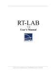
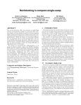
fidelity flight simulations. Simulink [Ref. 3] with Real Time Workshop [Ref. 4] provide a
user friendly simulation environment that eliminates the need for a skilled programmer to
produce most types of simulations. Simulink/RTW generate c programming source and a
stand alone executable from a Simulink symbolic diagram in one step, providing true
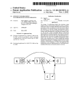
Pictures to Code capability as represented in Figure 1.
Matlab
/ Simulink
S-Functions
Non-linear 6 DOF EOM or
Auto-code
state-space or
Augmented
transfer function
non-linear
aircraft
Student pilot
simulation
Command
G
Compiled C code
output
Visu
al
K
Cues
Simulated
instruments
Figure 1 General User Progress "Pictures to Code"
3
Simulated Cockpit
View
Simulink is a graphical user interface for The Mathworks MATrix LABoratory
(Matlab) dynamic system simulation software. Essentially Simulink is an environment
that allows a user to program a problem graphically. Two additional capabilities allow
the system the power and flexibility required to provide unlimited growth of the basic
system. The first is an Applications Programmer Interface (API) which allows users to
create custom S-functions to extend the basic capabilities of the system. An S-function is
a user created Simulink function that uses compiled c code that is dynamically linked to
the rest of a simulation. S-functions are used to write functions to extend the basic
capabilities of the Simulink system. Since S-functions use c code, existing models can be
included in the Simulink environment allowing use of any of the built in Simulink
functions. An example is to start with Cal Poly s basic 6-Degree of Freedom airplane
model, convert the code to an S-function, then add a auto pilot simply by putting a
Proportional, Derivative, Integral (pid) function block in a feedback loop. To code up and
debug a pid compensator would take several days. Including one in a Simulink model,
wiring it up, and creating a set of gains requires about an hour.
A user created S-function can include just about any valid c function including
calls to hardware and communications. Simulink provides its modeling capabilities in
batch runs. The integration time step can be set to any value but the simulation runs as
fast as the processor can perform the calculations. Simulink does not come with any
functions to delay the code to the actual time increment set by the numerical integration
time step. An add on product called Real Time Workshop (RTW) adds real time
capability to Simulink along with three other functions. First RTW is a automatic c
language code generator. RTW generates compilable c code to create a stand alone
executable program that runs in DOS or Unix [Ref. 5]. Second RTW creates real time
4
code. To process simple equations of motion takes about a millisecond. RTW uses a
hardware timer driven interrupt to delay the program to equal the integration time step. If
a integration time step of 10 milliseconds (0.010 sec) is selected in the model, RTW
delays the program 0.009 seconds more so that the code is running at the same rate as the
integration step size. Third RTW combines hardware drivers into the program to drive
any device [Ref. 6] that can be connected to a computer. An inceptor device (input device
- eg. Joystick) such as the BG Systems FlyBox represented in Figure 2, is included by
wrapping the S-function IO code around the software drivers supplied by the device
manufacturer. The RTW software includes any custom S-functions as well as built in
Simulink blocks allowing applications
of any level of complexity. In theory
anything that can be represented by a
Simulink diagram can be simulated in
real time. Aircraft are complex
dynamic systems which are ideal for
Figure 2 FlyBox Inceptor
the Simulink/Real Time Workshop
pair. Real-time, or batch simulation and flight control law code is generated from a
Simulink model of an aircraft, subsystem or component. The ability to include hardware
drivers allows pilot in the loop as well as hardware in the loop and inflight simulations.
Since the simulations are created on a PC, tools used in research and industry become
available to anyone with the resources to set up, operate and program a PC.
TCP/IP protocols used for network/internet based communications can be
included as functions in the Simulink environment allowing computing to be distributed
to other machines. The software developed takes advantage of the fact that personal
5
computers are now fast enough to do a single sophisticated simulation task in real time
and inexpensive enough to purchase enough to do each of the tasks required. Networking
takes care of distributing the information each computer requires to complete its part of
the simulation. After processing is complete each computer either sends the data out as
output, such as graphics to a screen, or sends the data calculated back over the network to
the main computer. This technique is known as parallel computing.
The modular structure of model creation allow students to study the dynamics of
various aircraft from basic bare airframe aircraft to advanced artificially stabilized
aircraft with closed loop digital flight control laws. The aircraft can be simulated in a
variety of ways from a batch simulation with canned inputs on the desktop using a single
personal computer (PC) to real-time simulation on an easily re-configurable fixed-based
simulator including actual flight hardware driven by multiple PCs and or workstations.
The engineering student quickly builds and tests a model of a bare-airframe, designs the
control laws to tailor the response types and flying qualities [Ref. 7], then performs tests
of the resulting augmented aircraft via batch simulation or joy-stick inceptor on the
desktop PC or electronic force feedback inceptor in a fixed-based simulator. Using
Matlab/Simulink on a PC, consistent and verifiable real-time and batch simulation code
can be auto-coded from block diagrams representing the equations of the simulation and
architecture of the control laws.
The development of Fly-By-Wire (FBW) flight control systems has produced
dramatic advances in aircraft handling qualities and performance [Ref. 10]. However,
this increase in design complexity now requires extensive training and experience for the
engineer to be able to analyze these complex systems rapidly and cost-effectively. This
training is based upon fundamental understanding of highly coupled flight mechanics,
6
along with the fundamentals in FBW flight control systems. This combination of
disciplines must be tied together with hands-on experience working with control systems
dynamics. Demonstrating the resulting handling qualities to engineering students of their
designs of Fly By Wire flight control systems has been nearly impossible due to the
high cost of computer hardware and the long time required for skilled engineers to
program the source code for the simulation and the control laws. Frequency domain
analysis provides little intuitive basis for the student. The hands-on learning that spawns
mental connections between modal analysis and the time domain is best demonstrated by
pilot-in-the-loop simulation [Ref. 9]. Simulink/RTW provides a means to create a pilot in
the loop simulation. Seeing coupled responses such as a Dutch roll mode allows
correlation of magnitudes of the motion with the position and rate graphs.
Aircraft handling qualities analysis has traditionally been conducted by engineers
analyzing control systems with Computer Assisted Design (CAD) packages. Using
CAD, the engineers generate batch time or frequency histories [Ref. 15] of the designs of
the FBW flight control systems. The engineers do not interact with the design nor fly the
design. If a model exhibits complex cross coupling gaining, intuition of the plant is
impaired. The time required to write real-time simulation source code for control laws,
aerodynamic models and the hardware interfaces for a real-time simulation prohibits
engineers from direct interaction with their designs until the later stages of design when
changes are much more difficult. The ability to go from pictures to code allow rapid
development of prototype systems by substituting hardware drivers for simulated
components in an existing simulation then auto-generating executable code. An example
of the flexibility of the system is demonstrated by the difference in the amount of time
required to convert the code from c++ to S-functions and for students to create the same
7
simulation after the conversion. The conversion from c++ to S-functions took six months
whereas Sr. level undergraduate students were able to create complex models in hours.
Research Objectives
Originally the objectives of the research were to extend the basic capabilities of
the Cal Poly flight simulation laboratory providing a first and second order linear model
for the rotational axes of a Cessna 172 in landing mode. The model was to be used to
perform handling qualities research into the effects of time delay [Ref. 19, 20, 21, 22, 23,
24.] on the pitch channel of input using Cal Poly s force feedback stick and rudder.
However after the model was created, tested and verified a system was found that allows
rapid development of an advanced simulation lab. Using The Mathworks Simulink
graphical simulation environment as a base, along with Real Time Workshop auto coding
software to generate simulation executables from the Simulink models, a completely
modular simulator was established. Once the existing modeling software and hardware
drivers were incorporated, additional software tools were created to provide a system that
is inexpensive, flexible, powerful, easy to use and provides students with tools industry
and research are just starting to use [Ref. 9].
The Mathworks provides a API for including user created functions in
simulations. C MEX functions extend the basic matlab scripting language by allowing
compiled c language functions to be included in the Matlab workspace. Cmex Sfunctions allow users to create custom functions that can be included in Simulink models.
Since the functions are compiled very complex functionality can be added to the basic
Matlab/Simulink enviorinment.
8
Initially a Borland c compiler was used to generate C MEX and C MEX Sfunctions. After discovering that the scripts included with the RTW only supported
creation of C MEX functions, a Watcom c compiler was configured to create both C
MEX and C MEX S-functions. The supplied scripts were run using the example F-14
Simulink model and a batch mode program was created and the output confirmed with
the results published in the user manual. Using the numerical integrators created for the
F-4/F15 Phantom/EAGLE simulator (PhEagle) linear simulation, a procedure for creating
a S-function was established and verified against the data generated from the original
functions. Next a procedure for creating real time code was established and verified using
the numerical integrator S-functions and comparing the run time with an external clock to
verify the timing functions. The final verification was to compare Simulink s built in
integrators with the user created numerical integrators using the same integration
techniques.
After the procedure for creating S-function blocks was established, existing Cal
Poly c++ code used to access various hardware used for input and output to and from the
simulation cab was converted to Simulink S-functions. A 6-Degree of Freedom model
originally created to demonstrate program coding of a point mass model was converted to
a S-function and verified. Several functions were changed and several were added after
tools in Simulink and Matlab showed that the model was not producing acceptable
results. A Euler integrator and coordinate transform S-function was created to allow liner
transfer function and state space models to be flown in a virtual world.
Next, four models of varying complexity, modified to include pilot input and
graphical output, were flown to verify the concept and the ability of the auto-coder to
generate stand alone executable program code. Starting with a transfer function model,
9
then a simple one axis closed loop state space model of a X29-A fixed wing jet and a
complex state space model of a Kaman SH2-F with a closed loop flight control system
were modified to fly on the system. Next a model was created from the ground up to
provide fixed-wing six degree of freedom nonlinear equations of motion to fly open loop
as well as to provide a airframe to wrap closed loop flight controls around.
The models of the X29-A and SH2-F used for verification of the rapid
prototyping capability of the Cal Poly simulation lab had the control law gains optimized
using the CONDUIT software. NASA s CONDUIT [Ref. 8] is a set of utilities to perform
handling qualities analysis and control law optimization. Simulink based CONDUIT uses
the same models that can be easily modified to create a real-time simulation. The model
is created on a PC and then ported to a workstation for flying qualities analysis and
control gain optimization using CONDUIT. After the gain optimization has been
completed the gains can be reset in the original model on the PC and new simulation code
generated and flown immediately. This is the concept behind RIPTIDE [Ref. 9] (Real
time Interactive Prototype Technology Integration/Development Environment) a NASA
rapid prototyping project that uses RTW to generate simulations and eventually flight
control law code using Silicon Graphics IRIX workstations. The Cal Poly flight
simulation and controls laboratory duplicates much of the capability of the
CONDUIT/RIPTIDE system using networked PC s rather than expensive workstations.
Finally a procedure for performing model identification (verification) was
demonstrated using NASA’s CIFER [Ref. 12, 13, 15, 16.] software. Handling qualities
for many types of aircraft such as helicopters [Ref. 11] cannot be completely predicted
before the aircraft is built. For these aircraft NASA s CIFER (Comprehensive
Identification from FrEquency Response) program, is used to identify the characteristics
10
of the aircraft. The results of the data returned from CIFER can be used to correct a flight
simulation [Ref. 14] for further development of the aircraft and flight control system
[Ref. 13]. CIFER is a set of utilities tied together with a common interface that process
time domain [Ref. 12](frequency sweep) data into frequency domain data (bode plots).
Conducting a manual frequency sweep (CHIRP) provides data for the program to process
into transfer functions and stability derivatives. CIFER includes a utility to fit low order
transfer functions [Ref. 17] to the high order identified systems. Data created for the Cal
Poly simulation lab tutorial was processed using CIFER and a simple Simulink model.
The model and data were incorporated into a internet based tutorial to demonstrate
system identification to users of the Cal Poly simulation lab. A flight data collection
system created in the Cal Poly flight controls lab provides the capability to collect
frequency data for existing aircraft. The system uses low cost consumer grade sensors
sending signals through a pcm/cia A/D card to a laptop personal computer.
The system created is flexible, powerful, inexpensive, expandable, verified, and
easy to use, fulfilling all of the original design objectives. The software code generator
was also verified and includes the tools and techniques that can be used to verify future
simulation models
11
PhEagle I
PhEagle Hardware - Sim Cab
The heart of pilot-in-theloop simulation is the interface
between the pilot and the
simulation. Cal Poly s simulation
laboratory has a two seat tandem
fighter cockpit cab (Figure 3.),
with analog stick and instrument
computers to run the mechanical
Figure 3 PhEagle Simulation Cab
steam gauge instruments as well
as drive the force feedback torque motors for pilot force feedback or state cueing to the
center stick and rudder pedal inceptors.
Sim Cab F-4/F-15 PHantom/EAGLE
Cal Poly simulation cab, on loan from
NASA Dryden, combines an F-4 Phantom cockpit
with the center control stick from a F-15 Eagle
(Figure 4.) providing controls and instrumentation
on par with any modern high performance fighter
aircraft. The cab was originally used to train F-4
pilots then converted to a F-15 stick with force
feedback to the pedals and stick to conduct
Figure 4 F-15 Eagle Stick
handling qualities research. The force feedback
12
allows the cab to simulate actual aerodynamic control forces or feed back force or cueing
proportional to any of the aircraft s current states for research into the simulated aircraft s
handling qualities [Ref. 25]. The hybrid cab contributed to the simulation labs nickname
the PhEagle.
The force feedback stick provides Cal Poly with the ability to perform advanced
handling qualities research. Handling qualities is defined as flying qualities which allow a
mission to be accomplished with ease and precision [Ref. 7]. Feedback of the aircraft
states to the pilot is an important quantity to provide good handling qualities. Feedback
through the controls is important enough to be included in the MIL-STD-1797 [Ref. 7]
Military Standard Flying Qualities of Piloted Aircraft. However little information is
available about which states to feed back and how to cue the pilot through the controls.
The MIL-STD-1797 provides only basic guidelines for the force gradients and one state
in each control axis to be fed back (Table 1).
Table 1 Aircraft control Stick and Pedal Feedbacks
Axis
Feedback state
Force Gradient
Maximum Force
Pitch
Nz
8 lbf/g
50 lbf
Roll
Roll Rate — p
1 lbf/deg/sec
25 lbf
Yaw
Side Slip (Beta)
1 lbf/deg
100 lbf
The MIL-STD-1797 was used to set up the basic feedback for the PhEagle I. Two
types of pilot induced oscillation (PIO) can be predicted using batch and fixed base, pilotin-the-loop, simulation [Ref. 5]. A PIO is a phenomena where the pilot sends commands
to the plane in a cyclical fashion where his input ends up sending exactly the wrong
command to the airframe from the desired response. An example of this is trying to
13
highlight some text on a word processing document and over shooting the desired
sentence and then correcting up the page and overshooting again etc. Cal Poly s basic
simulation lab provides many capabilities that are available to anyone with access to
personal computers. The programmable PhEagle handling qualities force stick and pedals
allow Cal Poly to expand the knowledge base on pilot feedback.
Siblinc
The PhEagle’s dial instruments
are run through an analog computer
called the Siblinc. The input to the
Siblinc is in the form of reference
voltages sent from a PC through an off
the shelf digital to analog (D/A)
converter card. The voltages are
amplified in the Siblinc to drive the
instruments. The Siblink is the tall tower
on the left of Figure 5.
Figure 5 Siblinc and Stick Computer
Stick Computer
All of the functions of the stick are
handled through a separate analog computer
(the center tower in Figure 5.). The stick
computer buffers command inputs from the
stick, rudder pedals and two throttles
(Figure 6.) to the PC s analog to digital A/D
Figure 6 Engine Throttles
14
card and sends commands from the PC s D/A card through an amplifier to the sick and
rudder pedal torque motors. The amount of torque generated by the motors can be set
statically through the stick computers front panel or by varying the reference voltages
from the PC to the stick computer. The stick computer also sends back to the IO (PC)
computer stick position, force, and trim position and velocity. Feeding back force to the
position, virtual spring and damping can be created. By feeding back force and damping
proportional to any of the modeled states can be used to enhance the handling qualities of
an aircraft [Ref. 25].
PhEagle Hardware - Computers
The heart of the simulation lab is the computer network. There are 4 Pentium 166
MHz computers connected by Ethernet to provide the simulation dynamics, high
resolution texture mapped graphics and, input-output (IO) to the simulation cab. By
separating the simulation tasks to processes that are only dependant on input once each
integration time step or once every several time steps, a flexible computing environment
using as many or as few computers as are required for each simulation is possible. Since
the information is sent over a network the machine acting as the master controlling the
simulation could be any computer. Substituting a Unix workstation for a PC calculating
the equations of motion for a complex simulation such as a helicopter blade element
model running in real time would be seamless.
Low-cost PC s
Since each task in the system is performed on a separate PC with little special
hardware, upgrades to the system can be made incrementally, spreading the cost of
hardware upgrades over as much time as is required. Slower machines can be quickly set
15
up to perform the less processor intensive tasks such as IO. An additional cost savings is
achieved by using a switching box to allow the various computers to be controlled by one
monitor, keyboard, and mouse. The Instructor Station (Figure 7.) is the single point of
IO from the operator to the system. The graphics
computers have separate outputs to the out the
window screens.
Analog to Digital - Input
The A/D card uses variations in voltage as
input and converts the signal from a analog voltage to
a digital number corresponding to the level of
voltage. Potentiometers are used to vary the
Figure 7 Instructor Station
reference voltage from the stick and pedals. Any
device that can be connected to a linear or rotating potentiometer can be used for input to
the simulator.
Digital to Analog — Output
The instruments (Figure 8.) and
the force feedback are run using a
reference voltage sent out from the
computer then amplified to run the
actuators (voltage meters) in the
instruments and torque motors
connected to the stick and pedals. Any
Figure 8 PhEagle Instruments
device that can be controlled using a
voltage signal can be used as output from the D/A card.
16
Graphics Cards - Voodoo II
Graphics require the greatest
amount of processing power in a visual
simulation. The PhEagle currently has
provisions for up to 3 views, each view is
processed by a single computer
providing enough speed for real time
high resolution texture mapped graphics
Figure 9 Graphics Front View
(Figure 9). Each computer only requires
the position, orientation, and direction that the view is displaying. Each computer gets the
information once an integration step. The graphics are handled by providing three
computers with the same terrain database and software. By sending the position and
orientation to the three computers the rest of the graphics are processed separately. The
graphics computers’ only special pieces of hardware are network cards and Quantum 3D
graphics cards based on 3Dfx Voodoo graphics chips. The card provides hardware
texture mapping, z buffering, and Gouraud shading. The card has a pixel fill rate of 90
million pixels per second at 800 x 600 resolution, which translates to 5 to 10 thousand
polygons being shaded at 30 Hz. The three default views available in PhEagle I are out
the cockpit window, looking out the front and slightly to the sides. The view direction is
set on the computer that is doing the graphics for the view through the software. The
direction that the view is looking is simple to change allowing great flexibility in
placement of the side view monitors. Placing the side monitor directly to the side allows
for close formation flying while placing the monitors close together allows a wider
panoramic view out the front. The Center Monitor has the additional task of displaying
17
the Heads Up Display (HUD). While changing the HUD is not a basic task, various
HUD s can be substituted to test effects of symbology and HUD dynamics [Ref. 27, 28].
The graphics are not limited to three views. As many views are available as computers
that can be connected to the network and supplied with graphics cards. Tower views
can be processed on a separate computer with the same graphics set up and a graphical
model of the aircraft included in the visual database, using the position and orientation
information to position the aircraft model in the terrain database. Since the graphics
computers are only receiving position and orientation information and the source can be
anything it is possible to play back flight test data or previous simulations by sending
the saved state information to the graphics computers using a function to send the data at
the correct rate. Since the playback is not limited to real time, very long period
characteristics can be seen by playing the frames back quickly, or very short period
dynamics can be seen by playing back the data very slowly.
Network
The key to being able to use PC s is the Ethernet network. Using a standard
TCP/IP socket protocol the main simulation computer (the Spiegle) integrates the
equations of motion and sends out position and orientation information to the graphics
computers (the Eagle and Phantom), and state information to and from the IO computer
(the PhEagle). The network can support multiple simulations as sources providing mutiaircraft simulations such as formation flight, air to air refueling, and/or aerial combat.
Parallel Computing
Parallel computing is a technique used by super computers to split up tasks to
processes that can be done at the same time by separate CPU s. Simulation of any kind of
vehicle lends it self to parallel processing by having at least five separate tasks that need
18
to be performed at the same time. These include: Pilot input (stick)/output (instruments),
equations of motion, table look up of stability derivatives used by the equations of
motion, and out the window graphics. For a simple fixed wing rigid body aircraft the
single most computationally intensive task is the out the window graphics. Using a
Ethernet network and TCP/IP sockets for communication the tasks can easily be broken
up and run on separate computers, with each machine being sent the aricraft states over
the network. Separating the graphics from the flight model and having separate
computers process each view, frame rates exceeding 30hz for each view are possible.
The Cal Poly simulation lab currently has 4 166 MHz Pentium computers
Stick
S
Analog
&
I
Stick
B
Computer
Throttles
Instruments
Spiegel
PhEagle
Eagle
N
N
SIM
N
N
EOM
E
E
Graphics
T
T
Center
A/D
E
E
L
D/A
T
T
I
Drivers
W
W
Simulink
W
W
View
O
O
/RTW
O
O
(HUD)
R
R
Graphics
K
K
N
C
Graphics
Left
R
R
K
K
Right
View
view
NETWORK
Phantom
(Backup)
A/D
D/A
Drivers
Joysick
Keyboard
FlyBox
Stdout
Instructor —GUI
Virual/Actual Hardware
Figure 10 PhEagle I - Distributed Parallel Computing
(Pheagle, Spiegle, Eagle and Phantom) (Figure 10.), Ethernet hub, and simulation cockpit
cab with feedback stick and mechanical instrumentation, 3 high-resolution graphics cards
19
and monitors and computer code to simulate various aircraft and run and connect the
various pieces of hardware and graphics. Pheagle is the primary equations of motion
(EOM) engine and will control the flow of data to and from the other computers. In
addition to the EOM engine, the computer has one of the graphics cards to send graphics
to the left view (the side view requiring less processing not having the Heads up display
to process). Spiegle is the IO computer containing the A/D, D/A and digital cards that
process data to and from the sim cab and also has one of the side views to process. Eagle
is the main graphics engine that has the front view and HUD to process. Phantom is a
backup IO computer with Win95 for the backup functions and a partition of Linux to
provide remote access to the sim lab for researchers operating off site. Phantom is also
being set up to provide hardware in the loop support for remotely piloted vehicles using
the backup A/D, D/A cards and separate software from the stick IO to use the IO cards
for both functions at the same time. Using the TCP/IP socket software, several Silicon
Graphics workstations available can be included in the system to provide extra computing
power when required. The portability of C code allow functions programmed on a PC
system to be ported to the Unix computer when more computing power is required.
20
PhEagle I Software
The software originally written for the simulation system has gone through
several generations of development. The equations of motion, heads up display and
handling qualities tasks were originally written in c and Fortran for use on a Silicon
Graphics workstation. The software was originally encompassed by a project called
PANGLOSS named after the ever optimistic character Dr. Pangloss in Voltaire s
Candide [Ref. 26]. The PANGLOSS project has the lofty goals to create a complete
package of software that takes a design from a blank sheet of paper to a flying simulation
utilizing a complete set of stability derivatives. The project combines computer aided
drafting (CAD), computer aided Engineering (CAE), computational fluid dynamics and
simulation. As the project matured and PC s become more powerful, the simulation code
was ported to a PC and converted to c++. TCP/IP network socket and A/D D/A drivers
were written for the PC s and Graphics were created to work with the Quantum 3D cards.
Development of PhEagle I
Using c++ to develop the original software for the PhEagle has allowed rapid and
structured creation of the basic capabilities of the system. The system is run and
maintained by student technicians and researchers. To change the force set up on the stick
or verify the flight model requires an expert programmer familiar with the modeling
software and hardware drivers. The programmer must have a thorough knowledge of c++
programming, the source code, and the hardware as well as control theory. The c++ code
is powerful and flexible and allows the system unlimited expansion. It does require a
substantial investment to learn how the various parts of program code and hardware
interact.
21
Existing Simulation Tools
There are two main types of simulation of fixed wing and rotary wing aircraft:
batch and real time. Both can be further divided into categories that include various
combinations of simulated and actual hardware in the loop, and piloted, and pre
programmed automatic paper pilot inputs [Ref. 29, 30, 31.]
Batch simulation requires one or more computers and can include simulated or
actual hardware. Real time simulation requires one or more computers, actual or
simulated hardware. Piloted simulation also requires an inceptor device (possibly with
feedback), graphical or mechanical instrumentation, and one or more graphical displays.
To simulate an aircraft one must start with a basic set of equations of motion for
the aircraft and add complexity to simulate more complex behavior or include simulated
or actual systems into the basic system. The basic equations of motion for fixed wing
aircraft assume a rigid body. Actual aircraft are not rigid and most aircraft also contain
various complex systems that could be modeled.
Simulation of a flying vehicle can be done at a variety of levels of complexity
from treating the aircraft as a set of simple transfer functions, to a complex and coupled
state space system, to a basic nonlinear 6 degree of freedom (6 DOF) rigid body to a
complex modeling of all the known components involved [Ref. 32]. With the computing
power available with a single Pentium processor models up to a basic 6 DOF rigid body
can be included in a real-time pilot in the loop simulation. Batch simulations of any
complexity can be performed with the corresponding increase in processing time for the
additional complexity.
22
General
Using multi processor Silicon Graphics workstations and the built in TCP/IP and
shared memory capabilities native to Unix, simulations can be performed on a single
machine doing complex rotor state calculations using a joystick and one or more screens.
Simulator cab motion, more complex graphics, complex simulation of components such
as powerplants or navigation aids (e.g. inertial navigation) all require multiple computers.
Cal Poly
The software available for the PhEagle I lab include a three axis transfer function
model, a state space model, and a basic nonlinear 6 DOF rigid body model.
Transfer Function
A stand-alone three-axis transfer function model was created to demonstrate
transfer function models as a means of describing a dynamic system. The model was also
to be used for handling qualities research [Ref. 16] to provide a simple model with known
dynamics to vary control stick force shaping and processing time delay. The transfer
function model uses first and second order differential equations transformed through a
Laplace transform to the frequency domain [Ref. 33]. A transfer function is a ratio of
output to the input of a system over a range of frequencies. Using literal factors
approximations for the pitch, roll, and yaw axes, a simple model of the dynamics of an
aircraft can be rapidly synthesized [Ref. 32]. The first order system models an overdamped spring damper system that provides a variable delay to the system. A first order
function models the roll axis of a conventional aircraft. The second order system acts like
a spring damper system with the natural frequency and damping ratio variable. The
second order system is used to model the short period oscillations of an aircraft s
longitudinal (pitch) and lateral (yaw) axis. Each axis is isolated dynamically providing
23
great control over the model dynamics. Usually the system would be described as a state
space as described by Equation1. Integrating a state space usually requires a single
technique of numerical integration. Part of the reason for creating the model was to
Equation 1
•
X ( s) = AX ( s) + BU ( s)
Y ( s) = CX ( s) + DU ( s)
demonstrate Euler and Runge-Kutta numerical integration techniques. Each model was
set up to use separate numerical integrators for each output axis.
To perform the first order integration s a Euler numerical integrator was created
and tested using Matlab. Matlab was selected to take advantage of its interpreted
language which uses a syntax very similar to c. Note that by rearranging the terms of a
first order transfer function (equations 2-4) the Euler technique is derived. The results
Equation 2
10
Y θ
= =
s + 10 U δe
Equation 3
dθ
= −10θ + 10
dt
Equation 4
dθ = −10θdt + 10δedt
from the coded Euler integrator were compared to the Euler integrator supplied by
Mathworks. When the resulting plots overlaid exactly for the same input and time step
the function was included in the simulator.
24
The integration of the second order system transfer function used a Runge-Kutta 4
(RK4) scheme (equation 5). The frequency and magnitude matched exactly with the
Equation 5
1
Yn +1 = Yn + (k1 + 2 k2 + 2 k3 + k4 )
6
k1 = hf ( xn , yn )
h
k
k2 = hf ( xn + , yn + 1 )
2
2
h
k
k3 = hf ( xn + , yn + 2 )
2
2
k4 = hf ( xn + h, yn + k3 )
Mathworks supplied integrator. At .01 sec the difference was less than 0.25%. To verify
that 0.25% was within the range acceptable for accurate modeling a study was conducted
to compare the fixed step numerical integrators available form Mathworks as well as the
ones available from ISI in the System Build modeling software. At a dt of 0.05 using the
RK4 integrators and the same three transfer functions there was a 0.55% difference
between the maximum overshoots for the transfer functions. For a time step of 0.05 the
Mathworks integrators (Dormand-Prince, Runge-Kutta4, Bogacki-Shampine, Heun)
varied less than 0.5%. The Euler integrator response error was 100% using a 0.05 sec dt
compared with the other methods. The time step was reduced to 0.001 sec where the error
between the Euler method was reduced to less than 1%. The results of the study indicate
that caution should be taken to verify that a fine enough time increment is being used
when relying on the Euler technique.
To provide input and output for the integrators, code for a joystick and basic
software VGA graphics were obtained from a public domain simulator Build Your Own
Flight Simulator (BYOFS) in c++ [Ref. 34]. The code for the simulator was written in
25
Figure 11 BYOFS Original Screen
Figure 12 Snoopy Screen
c++, so the integrators were recoded in c++. The simulator was modified by removing the
original equations of motion as well as all unused game code. Two setup files were
included to store the calibration for the game joysticks and to store the springing and
damping ratios for the numerical integrators. The graphics were simplified to increase the
screen display area and simulate a simple Heads up Display (HUD) (Figures 11 & 12).
The new integrators were added to the simulators existing classes and the code modified
to provide input to the integrators. The output from the integrators was sent to the base
class while a linear airspeed was hard wired . State information was output to the
graphics and Heads Up Display. A second version of the code was modified by removing
the game joystick classes then combining graphics and equations of motion classes into
the stick and instrument classes in the PhEagle I c++ code. Modifications were then
made to the timing classes to change from a floating time scheme where the integration
time step is estimated from the length of the previous computational cycle to a fixed time
step were the length of the frame is hard coded and all of the computations must be
completed before the end of the frame. A fixed time scheme always involves unused
CPU time while the program waits to be released to the graphics. A fixed time step is
required to guarantee a smooth, accurate and consistent visual simulation.
26
Only simple tests using rules of thumb were used to test the integrators since the
functions had been tested in the Matlab environment. After brief testing it was observed
that the model didn t behave correctly to control inputs. The pitch always stayed in the
world axis while the roll and yaw were correct. The attitude dynamics were removed
from the simulator and a function was added to integrate body rates p, q, r (roll, pitch,
yaw) into the Euler angles Psi, Theta and Phi (yaw, pitch, and roll) in the world axis. The
Euler Transform also integrates the body linear rates u, v, w to the world positions x, y, z.
With all of the original game dynamics removed from the game simulator a basic IO
template was available to wrap around various dynamics models. Programs using the
game IO have been given the suffix snoopy to provide an indication of the IO used for
the programs.
The Euler and RK4 integrators original Matlab code have been incorporated in to
the FASAND simulator (described later) to demonstrate the use of numerical integration
to simulate several systems. The Euler integrator is being used to model simple actuators.
The RK4 integrator is being used to model engine dynamics.
State Space
A state space model is being developed to allow a model of any level of cross
coupling to be created and run with the PhEagle cab to allow handling qualities research
to be conducted. A state space is a linear system modeling primary axis (the output
desired) and cross coupling of control input to other axes. This capability is being
developed as a separate part of system development and will not be described at this time.
27
Basic 6-DOF Nonlinear, Rigid Body, Steady-State Subsonic Aerodynamics
A single point 6 degree of freedom nonlinear rigid body model of an aircraft [Ref.
32] was created to provide the basis for more advanced models. The simulation has been
divided into three main functions: Forces and moments, accelerations, coordinate
transform and state update. Figure 13 shows a symbolic representation of functions and
4
Unit Delay8
Psi
1
Unit Delay7
z
1
Unit Delay6
z
1
z
Mass
1
Mass
rho
rho
Ixx
Ixx
Iyy
Iyy
Izz
Izz
Ixz
Ixz
Fx
u
Fy
v
Fz
w
L
p
M
q
1
x
uDot
x
v
y
uDot
u
y
z
vDot
2
Psi
p
5
pDot
7
Alpha
Beta
4
Phi
r
Aileron
Aileron
Rudder
Theta
wDot
wDot
Elevator
N
3
Psi
Alpha
pDot
q
Airspeed
Forces Moments
Theta
Theta
8
Rudder
3
z
vDot
w
Elevator
2
r
Phi
Beta
9
Fx
Airspeed
Fy
qDot
qDot
Fz
v
rDot
L
w
rDot
M
Unit Delay2
Accelerations
z
Unit Delay4
Unit Delay
1
1
z
z
z
1
Unit Delay3
1
Transform /
Integrate
1
Unit Delay1
Unit Delay5
6
Phi
u
z
1
z
Figure 13 Symbolic Model of 6 DOF Functions
where the states are calculated. The diagram also shows how the states are used by the
other functions to calculate the forces and momentes or positions and orientations. It is
also easy to see where the final states are output. Note that in order avoid algebraic loops
a unit delay must be included in the feedback states. The aircraft is represented at any
time by the states summarized in Table 2. The states include the position and orientation
28
Table 2 State Vector
of the aircraft in
x, y, z
u, v, w
Location of aircraft in inertial coordinates
Body axis velocity components
p, q, r
Body axis rotation rates
Φ , Θ, Ψ
Aircraft Euler angles
inertial space, as well
as the body axis
velocities and
rotational rates. The forces and moments function starts with stability derivatives read in
from a ASCII based Standard Aircraft Data (SAD) file. The file contains 48 elements
describing the physical and aerodynamic characteristics of the modeled aircraft along
with some initial conditions for the flight condition. The function uses a single sad file at
one point in the flight envelope. The function is intended to be used as a quick check of
the dynamics of a developing aircraft at one point. To provide complete dynamics for a
training type simulator would require a complex lookup table that would require one or
more dedicated computers doing the interpolation from the look up tables. Table 3
summarizes the information contained in a typical SAD file.
Table 3. SAD File
100
1 Initial Altitude [ft]
0.002377
2 Starting Density [slugs/ft^3]
175.05
3 initial forward velocity U [ft/sec]
0
4 Starting Altitude [ft]
184
5 Wing reference area — S [ft^2]
33.4
6 Wing span — b [ft]
5.7
7 Wing mean aerodynamic chord- MAC [ft]
2750
8 Aircraft weight [lbs]
1048
9 Moments of inerita Ixx [slug-ft^2]
3000
10 Iyy [slug-ft^2]
3530
11 Izz [slug-ft^2]
0
12 Ixz [slug-ft^2]
0.41
13 CL1 - Initial total lift coefficient
0.05
14 CD1 - Initial total drag coefficient
0.05
15 CTX1 - Initial thrust coefficient
0
16 Cm1 - Initial pitch moment coefficient
0
17 CmT1 - Initial pitch moment due to thrust
29
0
18 Cmu - Pitch moment due to forward velocity
-0.683
19 Cma - Pitch moment due to angle of attack
-4.36
20 Cmadothat - Pitch moment due to rate of alpha
-9.96
21 Cmqhat - Pitch moment due to pitch rate
0
22 CmTu - Pitch moment due to thrust and u
0
23 CmTa - Pitch moment due to thrust and alpha
0
24 CLu Lift due to forward velocity
4.44
25 CLa Lift due to angle of attack
0.0
26 CLadothat Lift due to rate of alpha
3.8
27 CLqhat Lift due to pitch rate
0.33
28 CDa - Drag due to angle of attack
0
29 CDu - Drag due to forward velocity
0.0
30 CTXu - Change in thrust due to velocity
0.355
31 CLdE - Lift due to elevator deflection
0.00
32 CDdE - Drag due to elevator deflection
-0.923
33 CmdE - Pitch control
-0.074
34 CRollbeta Clbeta - Roll due to side slip (dihedral effect)
-0.41
35 CRollphat Clp - Roll damping
0.107
36 CRollrhat Clr - Roll due to yaw
0.134
37 CRolldA CldA - Roll control
0.0107
38 CRolldR CldR — Roll due to rudder
0.071
39 Cnbeta - Yaw due to side slip
-0.0575
40 Cnphat — Yaw due to roll (dutch roll)
-0.125
41 Cnrhat — Yaw damping
-0.0035
42 CndA — Yaw due to aileron (adverse or proverse yaw)
-0.072
43 CndR — Yaw control
-0.564
44 Cybeta — Side damping
0.0
45 Cyphat — Sway due to roll
0.0
46 Cyrhat — Sway due to Yaw
0.0
47 CydA — Sway due to Aileron
0.0
48 CydR — Sway due to Rudder
30
The model currently uses a Taylor expansion of the forces on a point mass to
model the linear accelerations (Table 4). Moments are then applied to a rigid body to
obtain the rotational accelerations. The translational forces are applied to the body in the
Table 4 Force and Moment Derivative Equations
C =C +C α+C β+C
qhat + C
phat + C
rhat-C
X
X0
Xα
Xβ
Xqhat
xphat
xrhat
D1
C =C
+C α+C β+C
qhat + C
phat + C
rhat+ C
delR
Y
YO
Yα
Yβ
Yqhat
yphat
yrhat
YdeR
C =C +C α+C β+C
qhat + C
phat + C
rhat +C
delE
Z
Z0
Zα
Zβ
Zqhat
Zphat
Zrhat
LdelE
C =C +C α+C β+C
qhat + C
phat + C
rhat+ C
delA+ C
delR
L
L0
Lα
Lβ
Lqhat
lphat
lrhat
LdelA
LdelR
C
=C
M
+C
M0
Mα
α+C
Mβ
β+C
qhat + C
Mqhat
phat + C
mphat
rhat+ C
mrhat
delA+ C
NdelA
delR
NdelR
airpath axis. Note that there is an assumption that the difference between airpath axis (the
direction the aircraft is going) and body axis (the direction the aircraft is actually pointed:
x out the nose, y out the right wing and z out the bottom) is small (small angle
approximation). This is only valid for small alpha and beta. As the small angle
approximation is exceeded the alpha starts to be mapped into drag and Beta reduces
overall drag causing changes in the aircraft dynamics. The control deflections are used to
determine additional forces and moments added to the aerodynamic forces and moments.
Once the total forces and moments are
Table 5 Equations of Motion
summed the forces and moments are
∂u/∂t = F /m- g sinΘ-qu+rv
applied to the mass and inertias of the
∂v/∂t = F
X
airframe to determine the translational
and rotational accelerations. Table 5
shows F=ma rearranged to a=F/m to
/m+g cosΘ sinΦ-ru+pw
Y
∂w/∂t= F /m+ g cosΘ cosΦ-pv+qu
Z
- I ]+ I pq)/I
∂p/∂t =( L+∂R/∂t*I -[I
XZ XX YY XZ
X
- I ]+R2I
P2 I
)/I
∂q/∂t =(M-R2 [I
XX ZZ
XZ XZ Y
— I ]-QRI +N)/ I
∂p/∂t =(∂P/∂t-PQ [I
YY
XX
XZ
ZZ
obtain the accelerations on the body. The equations include the gravity component in
31
each of the linear force terms. The body axis accelerations are integrated to body axis
velocities and rates. Table 6 shows how the body axis velocities are then combined with
the previous Euler angles to obtain the world axis velocities (Table 6) (u out the nose, v
Table 6 Euler velocity Equations
∂X/∂t = ucosΘcosΨ + v(sinΦsinΘcosΨ - cosΦsinΨ) + w(cosΦsinΘcosΨ+sinΦsinΨ)
∂Y/∂t = ucosΘsinΨ + v(sinΦsinΘsinΨ+cosΦcosΨ)+w(cosΦsinΘsinΨ-sinΦcosΨ)
∂Z/∂t = usinΘ + vsinΦcosΘ+wcosΦcosΘ
Table 7 Euler Rate Equations
∂Φ/∂t = p+(qsinΦ+ rcosΦ)tanΘ
∂Θ/∂t = qcosΦ - rsinΦ
∂Ψ/∂t = (qsinΦ + rcosΦ)secΘ
out the right wing, w down). The world axis velocities are integrated to obtain the current
position in the world (flat earth — X North, Y East, Z toward the center of the earth)
coordinate axis. Table 7 shows how the body axis rates (p about the long axis, q about the
wing axis, r about the vehicle vertical axis) are combined with the previous Euler angles
to obtain the Euler rates. The Euler rates are integrated to obtain the current Euler angles
Ψ - yaw (positive east and 0 degrees north), Θ - pitch (positive up and 0 degrees level
from the horizon - flat earth), Φ - roll (positive right wing down, 0 degrees no roll).
Finally the angles are reduced to remain in the first multiple of pi.
The model was originally created and tested as a Matlab m file program
(FASAND) to demonstrate the coding of 6 DOF equations of motion in a generic
programming language. The code is functional, however, on a PC the rate of integration
limits the usefulness as a research tool. The version intended to be used for batch
simulations is the Simulink S-function. In addition to the basic equations of motion the
FASAND code includes the wind2body transform function and the Euler and RK4
32
integrators. All the upgrades and bugs fixed in the Simulink 6 DOF S-function have been
included in the FASAND code.
33
PhEagle II
PhEagle II Introduction and Objectives
After adding several simulations to the Cal Poly simulation lab using c++ it was
found that it took months to understand the complete set of classes to perform all of the
functions. Each new function required intensive planning to include in the class structure
that existed. The RIPTIDE simulation environment was discovered that provided all of
the flexibility of the original c++ based system at Cal Poly while being function based
and graphically oriented. Since each function is self contained the system requires much
less coordination to develop. PhEagle II is a PC based rapid simulation environment
which uses the Simulink simulation environment as a base to tie all of the Cal Poly
simulation hardware and software into a flight simulation and controls laboratory. RTW
provides the means to create stand alone programs that include any combination of the
hardware and software.
PhEagle phase II took the existing hardware drivers and software and converted
the code to Simulink S-functions. The conversion and testing revealed that some of the
functions didn t provide satisfactory results. The functions were modified to include a
broader range of inputs and outputs and more complete modeling dynamics. Finally
several new functions were created to expand the basic capabilities of the system.
Simulink
Simulink is an add on package to Matlab that uses a graphical interface to allow
rapid modeling of dynamic systems. Through the graphical user interface provide by
Simulink, engineers get a visual representation of connections between the hardware, and
control system. Using Simulink as an interface to the simulation hardware drivers allows
34
the setup of the force feedback system to be performed by non-programmers. Software
tools were created to allow engineers to fly transfer function and state space models
that previously would have required expert programmers to create. Flying a transfer
function allows rapid development of preliminary designs. First cut designs use literal
factors to estimate the gross handling qualities for a design iteration by using spring and
damping values obtained from the literal factors. The Transfer functions are then
analyzed using frequency domain techniques. Finally, it is possible to use PhEagle II to
fly the equations. Gross handling qualities are rapidly evaluated early in a design
allowing more time to be spent refining performance and handling characteristics. Since
the RTW auto-coder creates a stand alone DOS executable program students can
substitute generic game joysticks and software graphics for the complex simulation lab
IO to allow code generated at the laboratory to be run on any PC.
The wraparound template that provides the input and output connection between
the function and Simulink is called a C MEX S-function. The user code is called through
an S-function in Simulink with as many input and output channels as required. The C
MEX API provides a gateway function to the Matlab environment, while the C MEX
S-function is the gateway to the Simulink environment. With a couple of restrictions,
most c code can be placed in the S-function template.
The first restriction is that only basic keyboard input is allowed. Mathworks
supplies a modified interrupt function for the keyboard which limits escape codes from
interrupting the program. To get around this restriction, a TCP/IP communications block
was created to allow communications outside the simulation software/hardware. This
allows the user to create a GUI using Matlabs programming language to provide the
35
instructor a graphical interface to control the simulation that runs as a separate process or
even on a separate computer.
The second restriction is that there is no direct support for graphical output. Users
can write their own graphics wrapped in the S-function template.
Keeping in mind the two limitations, just about any thing that can be written in c
can be used as an S-function including reading from and writing to hardware, storage,
TCP/IP communications, graphics, timing functions and custom math functions and
models.
Simulink model code is platform independent as long as only generic c S-function
code blocks are included in the model. This feature has the advantage that a model can
be created on a desktop PC, then be ported to a Unix based workstation. Using a
workstation, advanced analysis and optimization programs can be made available. The
speed increase possible using a workstation could allow real time execution if the model
is complex enough that real time execution is not possible on a PC. Some hardware
drivers can be ported between platforms as long as the c code is generic. The BG systems
FlyBox uses a serial port with generic c code drivers so the S-function drivers should
function on a PC as well as a Unix workstation. The generic nature of the c and Sfunction code was demonstrated by running the Euler S-function and the 6 DOF Sfunction blocks on both a PC and a several Silicon Graphics workstations including an
Indigo and an Onyx.
On a Windows 95 system the user can only use 32 bit program code to link into
the S-functions. This caused all of the 16 bit snoopy game IO functions used to test the
original desktop simulation functions to be abandoned. A new set of 32 bit game joystick
36
functions were found and graphics output were found that uses the World up virtual
reality viewer with the
output using OpenGL
(Figure 14).
Help files have
been provided by
creating a Matlab
script macro with the
same name as the Sfunction. Typing in:
>>help 6-DOF at
Figure 14 Screen Shot of World Up VR Player
the Matlab prompt will provide text to give the user background on the S-function 6DOF.
Modular Problem Setup
Models in Simulink can be created in small components to allow testing of each
component using various types of canned inputs to test the output of the component.
Since S-functions are functions, good programming practice of creating and testing small
components is encouraged. The 6 DOF was created using the function testing
methodology. The program was broken up into three major functions, forces,
accelerations, and transforms. Each component was wired up with constants and manual
calculations were compared with the results. When each function was producing correct
results the function was included into the main function. Throughout the development,
flexibility was constantly evaluated. Most functions can be built up from the basic
37
Simulink block set, however, when maximum performance is required compiled c code
usually provides increased speed.
Simulink Time block
Two methods are available to allow real time simulation through Simulink. Real
Time Workshop described earlier, and including a S-function timing block in Simulink to
time each simulation step and release the program when the end of the time frame is
reached.
Using an interrupt driven block of S-function code is being investigated to
provide real time capability in the Simulink environment using a PC s internal timing
chip. The amount of delay required is significant as the 6 DOF model finishes 10 seconds
of integration using a 10 millisecond integration step in less that a second.
Hardware Setup and Test
The hardware S-functions created to work with RTW were compiled to dll s to
determine if the functions would work in the regular Simulink environment. The driver
functions for the stick and the instruments function normally in the standard Simulink
batch mode. A delay function was required as a batch simulation finish time of 100,000
seconds finished in seconds. Since the drivers function properly in the standard Simulink
environment, Simulink can be used to perform force setup without a timing block on the
stick and pedals. To slow down the simulation, an extremely small time step for the
integration or including a delay loop to slow down the processing to close to real time is
required. Since the force stick hardware drivers do not require a specific time step, setup
of the stick forces is done without having to generate executable code which takes several
minutes each time.
38
Real Time Workshop
To generate the final executable program a Simulink model must include the
source code for all of the user supplied S-functions. Any custom functions that will run in
the Simulink environment can be included in the auto-coding to run in a stand alone
application.
Stand-alone Code
The real-time workshop code generator creates an executable that runs in the 32
bit DOS window of Windows 98. Using the TCP/IP connection, two forms of IO are
being provided that Mathworks didn t supply. There was no provision for keyboard input
to a real-time workshop application so modifying the program as it was running was
limited to using the supplied external mode interface which allows one process to run
Simulink coupled to another process running the real time application. This allows
Simulink to be linked with running simulation code providing the ability change control
parameters inside the simulation while the program is running. The user simply changes
the values in the Simulink block and the value is immediately updated in the running
program. This allows different control gain sets to be used during the simulation or
parameters such as time delay to be added to the simulation to demonstrate the resulting
deterioration in handling qualities. This also allows a separate computer to provide a
instructor station to control pilot in the loop simulations. Graphics is the second form
of output that is not supported by the RTW coder. Graphics has been in two forms: 1) an
interface to the World Up VR viewer was adapted to run through the Simulink
environment.and, 2) PhEagle I graphics are being added through the network capability
using the existing TCP/IP sockets. Since the graphics computers only require a state
vector providing position and orientation information, the Simulink model can use the
39
existing graphics by creating a TCP/IP to graphics S-function to plug into the graphics
TCP/IP server socket.
Hardware in the Loop
The ability to provide hardware in the loop code was the feature that initiated the
use of real time workshop. Since the PhEagle simulation cab uses A/D and D/A IO, the
simulator is already hardware in the loop. Using back up IO cards the hardware
capabilities exist now to include many types of flight hardware into the current system.
Existing Infrastructure
Creating the output to the instruments and the input from the stick has created a
infrastructure for doing hardware in the loop simulations. The input from the stick is in
analog voltage varied through potentiometers located on the stick. The instruments are
voltage meters that use the output reference voltage to command the position of the
needles. After all the stick and instruments are hooked up on Spiegel, unused channels
remain available on both the input and output cards that can be used for hardware in the
loop input and output. The addition of hardware requires very small changes to the
Simulink S-functions. The Phantom computer has D/A cards and software currently
being used as a backup system for Spiegel. Phantom is available to provide hardware in
the loop IO through the Ethernet.
PhEagle II — Software
Starting with bits and pieces of simulation and IO program functions created by
various Cal Poly alumni in Fortran, c, and c++, along with new functions, the PhEagle II
Simulink/RTW library was created, tested, and verified.
40
To confirm the program code, several complete stand alone simulators and IO
functions were written to test the new code before incorporating them into S-functions.
Where graphics and joystick input were required for verification, the Snoopy IO package
was used. Virtually all of the stand alone program code that was created for use in the Cal
Poly simulation lab has been converted to S-functions. The components have become
part of a simulation laboratory using the same hardware and software through the
conversion of the pieces to S-functions.
To verify the CMEX S-function, a first order Euler, then a second order numerical
integrator (using a Runge-Kutta 4 integration method) were placed into the S-function
template and imported into Simulink blocks. The Euler block was tested against a
Simulink first order transfer function using the Euler integration scheme. The RK4
integrator test code uses three different damping ratios corresponding to the commanded
pitch, roll, and yaw angles. The test sent three step input signals to the integrators. The
results were compared to the same system set up using second order transfer functions
and the built in Simulink RK4 integrators. Both functions matched with the Simulink
functions with less than 0.5% difference.
The next step was to create a transfer function model of the same system as the
custom S-function block. The values were entered into the block, the time step was set to
the same value, and Runge-Kutta was selected for integration.
To verify the process and accuracy of the code generated by RTW, the RK4
numerical integrators created to test the S-functions were placed in a new model and auto
coded in batch mode. The program was run and the results were automatically saved to a
text file for analysis. The results from the output file were compared with the output from
the PhEagle I numerical integrators, the original output from the S-function run in the
41
Simulink environment, and Mathworks’ versions of the RK4 integrator. The output from
the RTW generated code matched all of the other versions of the same code with the
same 0.5% variation between the new RK4 integrator and the Mathworks RK4 integrator,
verifying the batch mode.
Modular Structure
Conversion of the various functions required to create a simulation has reduced
the total number of lines of code that require maintenance. There is one copy of each of
the input, output, hardware, graphics, and flight models to keep track of. RTW creates a
simulation using the same S-function code tied to the icon in the Simulink diagram rather
than having a separate copy for each simulator as would be the case with stand alone
simulations. Since the RTW autocoder requires c source code for any of the S-functions
the functions are provided as open code to allow future researchers at Cal Poly to
update and modify the existing functions, or use them as templates to create new
functions to expand the capabilities of the system.
Adding new functions to the PhEagle II system only requires that the functions
use the S-function IO template. All other inputs and outputs requirements of the function
are labeled in the Simulink environment S-block. To make the block more intuitive, a
Mask can be put over the block allowing an icon of the functions use to be applied.
Including Existing IO Functions
All existing IO functions that were available as source code from PhEagle I were
converted from c++ code to c code. A new data structure was created that is compatible
with c. Error trapping that was originally part of a complex set of c++ classes were
incorporated into the functions as stand alone code. Only program code that was actively
being used was incorporated in the S-functions. While c code is less powerful than c++,
42
its similarity to other structured languages students have been exposed to allows less
experienced programmers to maintain the code and create new functions. Since Sfunctions are functions instead of programs, the development and testing process is
simplified.
Expanding the Possible
The process of separating the IO and modeling functions into Simulink Sfunctions without adding other functions provides greater flexibility to the researchers.
The ability to select and set up model components one at a time allows a simulation to be
built up and tested systematically to the level required for each kind of data collection.
Output - D to A
Starting with the c++ code created for PhEagle I, a Simulink D/A S-function was
created to provide input to a simulation from the PheEagle stick, pedals, and throttles.
The code had to be converted to c code to function inside the S-function template. The
process of converting the D/A driver to c necessitated several changes to the original
code. C++ uses classes as a structure to construct programs. C++ provides flexibility by
allowing generalized functions to be created. Since c++ is an extension of the c language,
all of the extensions had to be duplicated within the scope of the c language. Since the
flexibility (and complexity) of overloaded classes were not required for simulation, the
specific cases required for the S-functions were cut and pasted from the c++ classes.
Creating the D/A S-function required a new data structure, simplification of the
function structure, separation of the D/A and A/D functionality from a single function,
and simplified error trapping. To keep the functions as simple as possible the A/D and
D/A functions were separated into an input block and an output block respectivly. The
43
D/A (output) block is the code for both the 12 and 16 bit D/A cards. This is possible
because both cards use the same code with different base addresses and different offsets
for the resolution used by each card. C pointer arithmetic is still powerful enough to
provide the flexibility to handle 12 and 16 bit addressing in the same function.
Testing the function before it was included into the S-function template required
writing a stand alone program to send signals to the instruments. Once the functionality
was confirmed, the c code was stripped of the test function and placed in the S-function
template supplied by The Mathworks. The function was wired to constant input blocks
and a simulation was run. The functionality was first confirmed on a static set of inputs
and then on a set of dynamic sine function inputs.
Instruments
To simplify the setup of the instruments, the offset and gain from the digital counts
have been incorporated into the S-function code. The following instruments (table 8.) are
available through the S-function. There is also a basic S-function with just a basic set of
flight instruments and no stick force outputs. The calibration of the stick is in progress.
Basic stick dynamics and force shaping functions are in the process of being created.
Table 8 Instrument Output
Channel
1
2
3
4
5
6
7
8
9
10
11
Gauge
pitch8Ball (Pitch angle theta)
roll8Ball (Roll angle phi)
yaw8Ball (Yaw angle psi)
directinal Gyro(Yaw angle psi)
g meter Nz (g’s)
vertDevPoint
rudderball (Beta - side slip)
aoaMeter (Alpha -angle of attack)
mach meter
airspeed
sideslip angle (beta - sideslip)
44
Range - input units
+-Pi/2, rad
+-Pi, rad
+-Pi, rad
+-Pi, rad
-4 +9
+-1
+-1
-10 40, deg
06
0 700
+-15, deg
Output Units
deg
deg
deg
deg
g’s
deg
mach number
knots
deg
12
13
14
15
0
1
2
3
4
5
5
7
8
9
10
11
12
13
left engine rpm
right engine rpm
vertical speed indicator
vertical speed indicator
12 bit channels
right nozzel
left nozzel
internal pressure
course deviation indicator
cd horizontal indicator
cd vertical indicator
right engine temp
left engine temp
left fuel
right fuel
ptotal
stick pitch force
stick roll force
pedal yaw force
10 110
10 110
0 60,000
0 6,000
0 100
0 100
1 12
+-1
+-1
+-1
200 1,400
200 1,400
0 100
0 100
0 7,000
+-1
+-1
+-1
percent rpm
percent rpm
feet
feet/min
psi
deg
deg
percent
percent
psi
not calibrated
not calibrated
not calibrated
Input - A to D
The same changes to the c++ code were made to the stick, pedal and throttle A/D
functions. The function sets the gain and offset so that the input to the model is
normalized to +-1.
Stick
The stick was tested by connecting the stick block to a numerical output block and
scope to view the numerical and dynamic output from the stick block. The stick output
units were normalized to allow any commanded units to be set from the Simulink
diagram. Note that some of the ranges have reversed signs from the rest of the outputs
and the throttles are normalized to between 0 and 1. This has no effect on the output
from the S-Function as the output is a single numerical value per time step. Table 9
shows the inputs that are available from the stick through the stick computer:
45
Table 9 Cab Inputs
Input from cab
output range
pitch command angle
+-1
pitch force
+-1
ptich trim def
+-1
pitch velocity
+-1
pritch trim position
+-1
roll command angle
+-1
roll force
+-1
roll trim def
+-1
roll trim position
+-1
roll velocity
+-1
yaw comand angle
+-1
yaw force
+-1
yaw trim position
+-1
yaw control velocity
+-1
right throttle
+-1
left throttle
+-1
Feedback
Originally the feedback of the stick forces was done in the simulation code. The
S-function provides only a force input. Any feedback architecture is done in the Simulink
block diagram.
Force
The force at the stick is controlled by the gain input to the S-function. By feeding
back a state to the force input of the stick, cueing of the states is possible.
Active Sick Cueing
Creating canned responses to certain airframe or power plant states allows a pilot
to be cued actively that he is approaching a limit or a limit is changing. The most
common form of active stick cueing is a stick shaker to inform the pilot that stall of the
46
wing is imminent. A sine wave input with a frequency of about 5 hz would provide the
input for a stick shaker.
Graphics
Graphics is currently being provided by the World Up VR viewer. The graphics
for PhEagle I are still being developed and will be incorporated as soon as they are
available. The PhEagle I uses the Ethernet to send the data to the graphics hardware.
PhEagle Iionly requires a TCP/IP client S-function to access the remote graphics
computers. Graphics is a whole area that can be investigated. Since there can be more
than one computer processing equations of motion it is conceivable that any number of
computers can be added to the network to provide formation or air to air combat
simulation. A graphics subsystem can be created to handle expansions of the system
beyond PhEagle II.
Network (TCP/IP)
A TCP/IP communications template block is included to allow for future
expansion of the remote parallel processing capabilities of the PhEagle II system. The
block is being used to send states to the graphics computers. The block can also be used
for multiple aircraft simulations, playback of flight test or earlier simulation data to the
graphics system, and hardware in the loop simulation.
47
Key Features of Simulations
Stability and controls engineers use models of varying complexity to analyze and
design control systems for aircraft. These range from simple first and second order
differential equation models of the rotational and linear dynamics of only the primary
axis dynamics, to complex state space models, to full non linear equations of motion
models. To verify the 6 DOF non linear model, two state space models were created and
compared to the dynamics of the 6 DOF model. Finally a transfer function model was
created using the literal factors approximations for natural frequency and damping ratio
demonstrated in [Ref. 33]. The transfer functions were built up using the Euler block to
allow the model to be flown. The three models demonstrate the same aircraft modeled at
three levels of complexity and allow the models to be flown side by side to compare the
dynamics produced by each set of equations. The models will be described from the most
simple (transfer function) to the most complex (6 DOF) rather than the order they were
created.
Usually transfer function models are used for batch simulation to obtain time
histories or frequency domain plots of the motions to check individual responses of a
aircraft configuration to a control input. The models are used to get a feel for the basic
dynamics of an aircraft during the earliest stages of design. Flying the equations provide
a connection between the parameters obtained from the equations and how the aircraft
response is affected by changes to the parameters.
State space and full nonlinear simulations are usually done later in the
development of aircraft due to the overhead of coding the equations of motion and
control systems. Autocoding software allow models at any stage in the development of an
aircraft to be created and flown .
48
Since the transfer functions and state space models only provide perturbation
information some modifications need to be made to the simple models in order to be
flown .
Linear
The most simple and therefore the first kind of model used to analyze a new
aircraft is a linearized first or second order transfer function model. The basic flying
qualities can be estimated from these simple models with very acceptable results for a
first pass estimation. Using relatively few equations, a first cut gross estimate can be
made of the flying qualities of a proposed aircraft. The derivatives are estimated from
statistical data collected from sources like the Air Force DATCOM. The most simple
model created using the Simulink/RTW environment was a transfer function model. The
model was built up from loops to provide rate information to the Euler function block.
Figure 15. shows the same model as a transfer function, a series of loop closures, and a
w^2
s 2+2*z*ws+w^2
Step
Scope
Transfer Fcn
Scope2
rate
w^2
Step1
Sum
w
Sum1
1
s
Integrator
s
Integrator1
2*z*w
2zw
rate
input
position
Transfer function
Figure 15 2nd Order Transfer functions
49
psition
1
Scope1
subsystem with inputs and outputs. The Simulink diagram was built up using variables in
the blocks to allow the use of a initialization file to load the natural frequency (ωn) and
damping (ζ) variables into the model. This allows one model to be used and modified
quickly by loading various init files with variations in the model parameters.
Transfer function models treat an aircraft as a linear or rotational spring mass
system. The model has no motion except by being perturbed from a steady state. The
results are only valid for conditions fairly close to the steady state.
State space models can model off axis dynamics as well as on axis dynamics with
the most sophisticated models able to model all of the coupled dynamics for the
condition. These are still not as complete as a 6 DOF nonlinear model as aerodynamic
and other nonlinear effects occur off the trim condition. A model was created with
separate longitudinal and lateral state space matrices. The derivatives were
dimensionalized using Cal Poly Archangel v1.0 software. A second state space model
(figure 16) was created using a state space model used as an example in [Ref. 33]
50
.5925
57.3
u delta ft/sec
to knots
to deg1
p rad/sec
elev Elev
elevator
ail
Rud
Rudder
to command rad
Navion
Archangel 1.0
Longitudinal
StateSpace
theta delta rad
Stick
Altimeter 06000 ft
q rad/sec
q delta rad/sec
Pitch8ball + 90 deg
Y ft1
Long output
lat input
Yaw + 180 deg
phi delta rad
aileron rad
Out1
rudder rad
Roll8ball + 180 deg
r rad/sec
beta delata rad
Right Throttle
Left Throttle
Airspeed ,700 knots
X ft
In1
Ail
Aileron
rud
alpha delta rad
x’ = Ax+Bu
y = Cx+Du
x’ = Ax+Bu
y = Cx+Du
Navion
Archangel 1.0
Lateral
StateSpace
In1
1
p delta rad/sec
alpha rad
Z ft
gmeter 4 +9 g’s
to alt
psi delta rad
Alpha 10 +40 deg
r delata rad
beta rad
Psi rad
lat output
psi
deg Theta
Beta +1 15 deg
Lrpm 10 110%
u ft/sec
176.4
Rrpm 10 110 %
Sum
ft/sec
Theta rad
Theta
deg Phi
Vert speed + 6000 ft/min
0
v ft/sec
Yaw Force +1
Constant
0
Phi rad
w ft/sec
Phi
deg Psi
Constant1
Roll Force +1
Pitch Force +1
Euler Transform
to deg
Instruments & Force
57.3
to deg2
|u|
Abs
Figure 16 Archangel State Space Model
Modifications Required to Fly
Flying a linear transfer function and the simple state space models require
giving the model a steady state motion to be perturbed from. Starting the model from the
trim (Initial) condition and performing a numerical integration on the differential
equations allow the student to see the effects of perturbations on the math model. The
state space model has the speed directly connected to the throttles with the perturbations
from the model summed in before the speed is fed to the Euler block.
To be able to fly the aircraft the equations need a world to fly in and the
capability to be oriented in the virtual space. In a standard simulator this is done by
defining and keeping track of the position and orientation using world coordinates and
the Euler angles Psi - compass heading, Theta - pitch (angle above or below the
horizon), and Phi - roll angle. The definition of the orientation must be in this order or the
virtual aircraft will have an orientation other than the one expected. The World Up
51
viewer has the end of the runway conveniently located at the (0,0,0) location in the
virtual world. This makes setups for basic tests rapid and simple. The World up viewer
uses quaternions to keep track of the world angles, but the models do not yet so it is still
possible to stop the simulation if the model passes through straight up or straight down.
In addition to having a space to fly in, the model requires commanded input and
output to allow the pilot to observe theresponses.
Euler Block
To allow a transfer function model to be flown , a Euler S-function block was
created to give position and orientation to the simple model which supplies rate
information. The Euler transform was separated from the 6 DOF simulator and converted
to a stand alone S-functions. The block takes in as part of the parameter set up the initial
position, orientation and velocity. The block starts using the initial position and
orientation, then takes in angle rates in the body coordinates and integrates them to get a
change in angle then transforms the body angles to world axis to orient the aircraft. The
velocities are transformed from the body axis to the wind axis through the angles alpha
and beta. The transform from body axis to wind axis is the transpose of the transform
from wind axis to body axis used in the 6 DOF model. The alpha and beta inputs allow
the model to take in angle of attack and sideslip angles from a state space model and have
the aircraft oriented correctly. The wind axis velocity components are transformed
through the Euler angles to the world axis. Finally the wind axis velocity components in
world coordinates are integrated to get a change in position in the world coordinate axis.
To test the block, the velocity and angle rates were connected to constant value
blocks in Simulink and integrated for several seconds. Once the proper dynamics were
52
observed, the Euler block was flown using the stick and no other dynamics to confirm
the correct responses to the commanded input rates.
Trim Attitude and Speed
Since the model is linear and actual aircraft are highly nonlinear, the model is
valid only for small perturbations from the initial trim conditions. It is difficult to see
when the model has departed from the conditions where the model is valid. Since the
same model is available in the three levels of complexity a side by side comparison of the
models is possible.
Feel
Transfer function and state space models are perfect for setting up and
determining the feel system dynamics. Models with known dynamics can be quickly
created to test various states fed back to the feel system to determine if feeding back the
state has positive, negative, or no effects on the handling qualities. The effects of the feel
system itself can be modeled and tested by using a simple but known transfer function to
determine the effects of the dynamics of the feel system. For example if the Nz/dE (g
forces to elevator deflection) transfer function is known, the pitch feel system can use the
output to send to the stick force.
6-DOF Non linear
Non-linear simulations require no modifications to the auto-coding process. The
S-function containing the non-linear equations of motion are included in the Simulink
model and connected to the aerodynamic, gear, and thrust model. The source code is
placed in the Matlab search path to allow the code to be included in the final program.
53
The 6 degree of freedom (3 translational and 3 rotational degrees) non-linear rigid
body model created for PhEagle II started as a Fortran program demonstrating a very
basic nonlinear simulation. The code was converted to a Matlab program called
Fundamentals of Aircraft Simulation And Nonlinear Dynamics (FASAND) then
debugged before conversion to a Simulink S-function. FASAND is used in the
simulation lab to demonstrate the use of batch simulation and coding of the equations of
motion. Matlab code is very similar to c code so very little change was required to
convert to a C MEX S-function. The nonlinear S-function block allows the PhEagle II to
model bare airframe dynamics as well as closed loop control systems for aircraft.
The original model made two assumptions that produced dynamics that were not
satisfactory. First the model originally assumed a trim condition were the thrust equals
the drag and the rotational moments are all balanced in steady state. This was a gross
simplification that resulted in an unstable long period (phugoid) mode. Using the
assumption simplified the development of the equations of motion since a trimmer did
not need to be run before each simulation. The simulation was modified to have the base
drag for the condition input through the SAD file and the thrust is set to a constant value
equaling the trim drag from the SAD file. The drag changes with changes in velocity
while the thrust remains constant. The model still assumes balanced moments as initial
conditions. Future changes to the model will necessitate determining the trim (steady
state) condition to start the model. This can be done manually by varying the parameters
until the state desired is achieved or can be automated by the creation and use of a
trimmer (a program to alternately vary a control then integrate the model a few time
steps until the steady state condition desired is achieved). The model required manual
trimming of the altitude, speed and density from the published values in [Ref. 33]. The
54
original published values were sea level, 176.4 ft/sec, and 0.0023769 slugs/ft^3. The final
values established for trimming the model are: 2.153 ft, 175.215 ft/sec , and 0.00237254
slugs/ft^3. The atmosphere was trimmed rather than the controls as the model is assumed
to have the controls trimmed for the condition. Before the trim of the model was refined
the initial conditions perturbed the model enough to excite the phugoid mode at the start
of a simulation. For a man in the loop simulation the small perturbation was not
distinguishable, however the motion was significant in batch simulations during
validation of the model.
The second change from the most basic model is to correct for the assumption that
the aircraft body axis is the same as the airpath axis (the difference between the direction
the aircraft is pointed and the direction it is actually going). Originally the model was to
only map the lift and drag forces to the body axis [Ref. 32]. After referencing the PhEagle
I c++ code, the PhEagle II S-function included the side forces [Fy] to the coordinate
transform. The transform was done in two stages from airpath axis through the angle beta
along the airpath z axis (equation 7.). Then through the angle alpha along the beta y axis
Equation 7 Wind to β
cos(β ) sin(β ) 0 DragWind Fxα
− sin(β ) cos(β ) 0 * FyWind = Fyα
0
1 LiftWind Fzα
0
Equation 8 β to Aircraft Body
cos(α ) 0 sin(α ) Fxα FxBody
0
1
0 * Fyα = FyBody
sin(α ) 0 cos(α ) Fzα FzBody
to the aircraft body axis (equation 8.). The
transform were multiplied together then
multiplied by the force vector to obtain the
final transform matrix (equation 9). The
Equation 9 Total Transform
cos(α ) 0 sin(α ) cos(β ) sin(β ) 0 cos(α )cos(β ) − cos(α )sin(β ) sin(α ) DragWind
0
1
0 * − sin(β ) cos(β ) 0 = sin(β )
cos(β )
0 * FyWind
0
1 sin(α )cos(β ) − sin(α )sin(β ) cos(α ) LiftWind
sin(α ) 0 cos(α ) 0
55
difference between the two axes are the angle of attack (alpha) and the side slip angle
(beta). In actual flight the airpath and aircraft body axes rarely coincide. The effects of
the difference in angles adds to the overall drag as some of the lift is mapped to the drag
and some of the original drag is mapped to the down force [+Fz] of the aircraft and
therefore affects the natural frequency, and damping, of the longitudinal and lateral long
period oscillations. The simulator originally did not re-map the forces calculated in
airpath axis to the aircraft body axis. The re-mapping of the forces changed the dynamics
of the model so that there was much less climb associated with a step input of negative
(up command) elevator. The re-mapping of the forces also affected the natural frequency
and damping in the long period [phugoid] mode. Re-mapping added damping to the
system and decreased the natural frequency. Figure 17 shows the changes in ζ, ωn and θ
Pitch Rate and Angle With and Without Forces to Body Axis
3 mapping of the lift force into the drag force.
for the
Angle
Angle body
Rate
Rate body
2
1
0
1
2
3
4
5
6
7
0
20
40
60
80
100
Figure 17 Navion Long Period Longitudinal Dynamics
56
120
140
160
180
200
The model assumes a trim alpha angle and balanced initial moments. The
program will require changes to include the trim alpha and initial moments to determine
the trim elevator position.
The point mass model can model-fixed wing aircraft, spacecraft, and basic
dynamics of rotorcraft (without the rotor dynamics). The atmosphere model extends high
enough to allow aircraft that require reaction controls to be tested.
The input for the model is a ASCII text file in the format of the Standard Aircraft
Data SAD file. The filename is set by double clicking on the 6-DOF block and changing
the name in the parameter block for the function. The block was initially tested outputting
only the position and orientation states. After working with the model it was found that it
is desirable to output all the states available and to separate some of the inputs to separate
functions (Figure 18.). The density of the atmosphere was sent in as a input from a
separate function to allow more simple or more complex models of the atmosphere to be
added. Additional forces and moment inputs (Figure 18) have been added to allow for
more complex components to be added such as landing gear. The additional force and
moment inputs allow for turbulence, transonic and supersonic aerodynamics, non rigid
body dynamics as well as rotorcraft blade element dynamics to be included.
57
Unit Delay
1
z
elevator
elev
x (ft)
Elev
Elevator rad
y (ft)
Ail
ail
z (ft)
Aileron
Airspeed ,700 knots
Aileron rad
Psi yaw (rad)
rud
psi
Theta pitch (rad)
to command rad
Rudder
deg Theta
Rud
Theta
deg Phi
Phi
deg Psi
Rudder rad
Phi roll (rad)
Temperature F
Pressure lb/in^2
Alt ft
u Forward ft/sec
u
v Right ft/sec
v
w Down ft/sec
w
knots
a ft/sec
gmeter 4 +9 g’s
Atmosphere
Alpha 10 +40 deg
Fx lbf forward
p roll rad/sec
throttle
Pitch8ball + 90 deg
Yaw + 180 deg
Right Throttle
Left Throttle
Altimeter 06000 ft
to alt
Roll8ball + 180 deg
to deg
Rho slu/ft^3
Density slug/ft^3
1
to airspeed
thrust lbs
Beta +1 15 deg
q pitch rad/sec
Stick
thrust
0
Fy lbf right
Alpha rad
Rrpm 10 110 %
57.3
Vert speed + 6000 ft/min
Fz lbf down
Beta rad
f2
to deg1
57.3
to deg2
qdot pitchrad/sec^2
Pitch Force +1
rdot yaw rad/sec^2
f4
Abs
Roll Force +1
M Pitch ft/lbf nose up
f3
0
|u|
Yaw Force +1
pdot roll rad/sec^2
0
Lrpm 10 110%
to ft/min
r yaw rad/sec1
f1
0
60
Instruments & Force
L Roll ft/lbf right wing down
udot Forward ft/sec^2
vdot Right ft/sec^2
0
N Yaw ft/lbf nose right
f5
vdot Down ft/sec^2
Point Mass 6 DOF
Non Linear
1/32.2
to g’s
Figure 18 PhEagle II - 6 DOF Model
There is a built-in Simulink function which passes the time step to the S-function
code such that the Simulink environment sets the time step for simulation. The Sfunction will take and use any size time step for the numerical integrators that
environment passes in. Passing the time increment into the existing code, the new code is
not limited to a hard-coded dt and can run at whatever time step the rest of the model is
using. The model uses a course time step of 0.0417 sec (24 HZ) for real time simulation
and as fine as required for batch simulations. The Mathworks supplies integrators that can
be used by code in the S-functions, but for many users that have existing math models,
Simulink provides the ability to wrap the S-function IO around the existing code. The
equations of motion can then be imported to the Simulink environment as a block to wrap
a control system around. Mathworks supplies a make script to include all of its libraries
58
that are required to complete the programs. The script adds the code, then compiles
completed code into a 32 bit dynamic link library (dll) [win95] or the equivalent in Unix.
59
6 DOF Model Verification
The 6 DOF model used a L17 Navion piston engine, propeller
driven light Air Force liason aircraft
shown in Figure 19. for validation.
Figure 19 L-17 Navion
The aircraft was used to demonstrate
stability analysis calculations in [Ref. 33] Using the state space model, as well as input
from undergraduate students testing the FASAND program, several errors were found in
the first edition of the text book that were providing dynamics that were inconsistent with
an aircraft of the type modeled in the text. The roll control derivative was off by two
orders of magnitude causing a roll time constant of 17 seconds rather than 0.15 sec. The
yaw-roll (Clδr) coupling was off by an order of magnitude causing a severe dutch roll.
The sign for aileron control (Clδa) was reversed. The results produced reversed roll
responses in the state space and 6 DOF models. Since the FASAND code runs as a batch
at close to actual time using fairly large time steps the initial verification consisted of
checking various dynamics by hand calculating time constants and damping ratios using
the published characteristics.
To have a complete baseline set of dynamics, the stability derivatives were
entered into the program Archangel. The program dimensionalizes the non-dimensional
derivatives, given a set of initial conditions, then combines and arranges the derivatives
into two state space systems for the longitudinal and lateral directions. A second state
space was set up using dervatives published in [Ref. 33]. The two state spaces matched in
most places however there were a couple of places that the dynamics differed. The State
spaces were used to create flying models for the PhEagle lab and to set up as Linearly
60
Time Invariant (LTI) systems in Matlab to obtain time histories to compare to each other
and the 6DOF simulation. The LTI systems used a unit step input while the 6 DOF model
used a 2 degree step input to scale the response so that they could be compared on a time
history. The perturbation was kept small in the 6 DOF in an attempt to keep the dynamics
as close to the linearized system as possible, however the stepsize could still be large
enough to introduce the nonlinear effects for the non-linear model. Note that in all the
graphs the 6 DOF response is the dotted line. The first axis compared was the pitch in the
short period. Figure 20. shows the two state space models have very similar short period
Impulse Response
Pitch Angle
0
State Space
6 DOF
Amplitude
0.5
1
1.5
2
2.5
0
0.5
1
1.5
2
2.5
3
3.5
4
4.5
Time (sec.)
Figure 20 Theta to Elevator - Short Period Longitudinal Dynamics
wn and damping while the 6 DOF is less damped and higher frequency. The Long period
dynamics show similar differences between the state space models and the 6 DOF. The
wn is higher and less damped than the state space but the time constants are the same.
The pitch angle response (figure 21.) is one where the state space models differed. The
natural frequency of the 6 DOF model falls between the two state space models. The 6
DOF model shown in Figure 18 has the correction for the forces mapped from the wind
axis to the body axis. The effect of the mapping is to decrease the natural frequency and
increase the damping in the long period dynamics. Figure 21 shows the decrease in
natural frequency from the Archangel model, and the decrease in damping compared to
61
both models. The two state space models in the lateral axis provided the same response
Impulse Response
Pitch Angle
Amplitude
1
0
1
State Space
6 DOF
2
0
20
40
60
80
100
120
140
160
180
200
Time (sec.)
Figure 21 Theta to Elevator - Phugoid
for a step input. The 6 DOF in rudder to beta (figure 22) exhibits a similar difference
from the state space models as the pitch response. Figure 20. shows that the 6 DOF model
is less damped and a higher frequency than the state space models. The mapping of the
forces reduce the drag for a sideslip condition by mapping the drag to a drag and a pure
side force. The result is a higher frequency than the model without the mapping and less
damping than the unmapped model. The Roll rate to aileron (figure 22) response matched
the state space the closest. The roll angle response also exhibits the same difference in
natural frequency and reduced damping compared to the state space model. Both models
show the same under damping and the washout of the angle due to the dihedral effect in
the wings. Figure 23. shows the characteristic washout of the roll angle due to the
dihedral effect. Without flight test data further refinement of the model is not possible.
The model has demonstrated the correct behavior that an conventional airplane would
display to the control inputs, with the time constants approximately correct and damping
close to a linear model. The final verification used the World up viewer to display an
external view of the model to view the coupled responses. The same step input was
62
Impulse Response
Beta
1.5
Amplitude
1
State Space
6 DOF
0.5
0
0.5
1
0
5
10
15
20
25
30
Time (sec.)
Impulse Response
Roll Rate
Amplitude
25
20
15
State Space
6 DOF
10
5
0
0
5
10
15
20
25
30
Time (sec.)
Figure 22 Lateral - Beta to Rudder and P to Aileron
applied to the model and the graphical output was observed. For pitch both the short
period and phugoid were observed in the correct magnitudes. A step input to the roll
control resulted in adverse yaw (yaw away from the roll input) and finished with a roll
angle in the direction of the control input. The roll angle washed out and a spiral
divergence was initiated. A pulse to the rudder displayed the charateristic rotation of the
tail of the airplane in the dutch roll mode with a entry into the spiral mode from the
induced roll angle once the dutch roll died out. Tools described in the CIFER section
provide the information that will allow a complete verification of the model with an
actual aircraft.
63
Impulse Response
Roll Angle
3
Amplitude
2.5
2
1.5
State Space
6 DOF
1
0.5
0
0
5
10
15
20
25
30
Time (sec.)
Figure 23 Roll Angle Response
Standard Atmosphere
A C MEX S-function block was created (Figure 24) to replace the hardwired
atmosphere function. The original function estimated the atmosphere up to the first
isothermal layer. This
limited the function
Constant 459.67
to altitudes less than
1.8
36,090 ft the cruising
to Rankine
to F
.00014503
altitude of
1
Alt ft
3.281
std_atms
Demux
SFunction
To meters
To psi
019403
commercial airliners.
To psi1
3.281
The S-function
To ft/sec
1
Temperature F
2
Pressure lb/in^2
3
Density slug/ft^3
4
a ft/sec
Demux
standard atmosphere
Figure 24 Atmosphere Conversion from SI to English Units
function calculates
the pressure, temperature, density, and speed of sound up to 47 kilometers or about
155,000 ft. using altitude as an input. Using the altitude output from the 6-DOF function
required including a unit delay block in the Simulink model to avoid a algebraic loop.
The delay and initial condition must be set to match the models starting altitude and time
step. The C MEX S-function does the calculations using SI units, the conversion to
64
English engineering units is done in Simulink as shown in Figure 24. The block takes in
as parameters the sea level temperature and pressure. This allows the user to set up nonstandard conditions to match flight test data that has not been normalized. The input is in
Kelvin and Newtons/meter^2.
Input
Creating the 6 DOF model as a S-function allowed the model to use any of the
canned inputs available from Simulink as well as the new PhEagle stick input block.
The ability to use the standard Simulink/Matlab functions allowed the analysis of the
aircraft to be done all using a single CAD/CAE package. Access to a workstation allows
CONDUIT to be used to analyze a bare airframe or optimize a control system. A paper
pilot would be a matter of creating Simulink subsystems or S-functions to model piloted
inputs.
Output
The output has been expanded from basic text screen output and basic graphics to
the Simulink scope, to workspace function, to file as well as numerical output and
advanced graphics of the World up viewer and PhEagle I out the window graphics. The
ability to produce ASCII file output of the control inputs and airframe dynamics allow the
use of the NASA program CIFER for simulation model verification. A function has been
created to convert ASCII files to Fortran unformatted binary files. CIFER requires a
Fortran binary file of the input and output for each channel desired for identification.
Feel
With all of the states being written out, actual aircraft control feel as well as
artificial state feedback feel can be incorporated with the 6 DOF model. By making the
feel proportional to the dynamic pressure and Nz the actual feel of an aircraft can be
65
modeled. By feeding back any of the other states the effect on handling qualities can be
investigated.
66
Control System - Closed Loop
Using Simulink/Real-time-workshop PhEagle II allows engineers the capability to
rapidly create simulations of closed loop flight control systems. These can be systems
closed around state space or full nonlinear aircraft models. The ability to model closed
loop control systems allows students and professional engineers to fly the aircraft/flight
control system to confirm analysis of the control laws. Classic linear analysis only looks
at one or two axis at a time. Flying the model tells the engineer right away if there is
something that requires more detailed analysis or optimization. Flying the closed loop
full state model of the Kaman SH-2f gave a researcher insight to behaviors in the aircraft
that were part of the physical system that could not be compensated with the flight
control system.
User manual - Intranet/Internet
Using a combination of intranet and internet web pages the documentation for the
simulation laboratory is maintained on the host computer with the basic instructions
being the home page of the browser on the PhEagle computer. The rest of the information
publicly available will be kept on the locus web server: http://locus.aero.calpoly.edu/sim
Source code for the PhEagle II will be kept on the PhEagle computer and the FASAND
source code on the locus server sim page. The www web page describes the facilities and
software capabilities of the PhEagle system and the simulation and controls laboratory.
Verification of Concept
To validate the software aspects of the pictures to code concept, several models
were modified to allow inceptor input and graphics output using NASA Ames RIPTIDE
[Real-time Interactive Prototype Technology Integration/Development Environment]
rapid simulation facility. The facility at the time consisted of a SGI ONYX with 4
67
R10000 processors an inceptor Flybox and high resolution texture mapped graphics
database which includes a basic heads up display (HUD) system. The RIPTIDE system
was verified using a verified GENHEL blade element model of a UH-60 helicopter.
Three models were used to conduct the test which was done in four stages: The
Flybox and graphics were tested using a simple transfer function model to test the Euler
motion and orientation block. A simple one axis state space model of the X-29A in pitch
was modified with transfer functions for yaw and roll and given motion with the Euler
function. A complex state space model of a Kaman SH-2f with a model following flight
control system was modified to use the Flybox and graphics. And the 6 DOF nonlinear
model of a Navion liaison aircraft was connected to the Flybox and graphics and flown.
CONDUIT
The feedback and feedforward gains for the X-29A and the SH-2F were obtained
using NASA Ames CONDUIT (CONtrol Designers Unified InTerface) software.
CONDUIT is a collection of aircraft handling qualities evaluation [Ref. 18] and
optimization tools. CONDUIT works to find a optimal solution satisfying multiple
handling qualities metrics (specs) and all the potentially competing requirements. The
researchers created the control system architecture and applied the handling qualities spec
to constrain the design problem to reach a solution. Altering the control system gains to
satisfy all the imposed HQ specs at the same time improved handling qualities. Usually
only a few handling qualities specs can be satisfied for any design because of the time
involved in checking the spec for a new gain configuration.
The X-29A and the SH-2f models used verified state space models from NASA
Dryden and Kaman corporation as part of NASA/Cal Poly research projects into control
system optimization research. The researchers started with the control systems used for
68
the actual aircraft as a baseline then modified the architecture to improve the handling
qualities optimizing the gains using CONDUIT after each modification. Dozens of
configurations were tested before the final architecture was achieved.
The pictures to code model of the SH-2f was used by the researcher to confirm
the control behavior and to observe the degradation of the control laws as the trim
condition moved away from the baseline used to generate the control system gains.
X-29A - Pitch axis only, State
Space, Fixed Wing Model With
Feedback
The first aircraft model used
was a thesis project completed at the
NASA Ames research center by Mark
Morel. The aircraft model is a
verified pitch axis only state space
model of the X-29A (figure 25.)
provided by NASA Dryden research
Figure 25 NASA X-29A
center with a quickness pre-filter added to the original control system to improve the
handling qualities. After adding the quickness filter, the system gains were optimized
using the CONDUIT software. The trim speed of the model is 726 feet/second.
Modifications Required to Fly
The Simulink model of the X-29a contains outputs for: Forward velocity (body
axis), alpha (angle of attack), q (pitch rate), theta (pitch angle world coordinates), Nz
(g s), stick actuator rate, flap actuator rate, and canard actuator rate. The outputs from the
state space are all perturbations from a steady state. An example is that even though the
trim speed of the model is 726 feet/second, if the speed output from the state space is fed
69
directly to the Euler block the output speed is zero until the system in perturbed then the
speed just oscillates until trim is achieved again which is 0 ft/sec. The output speed was
modified so that the output from the model was summed with a constant input block in
(figure 26.) the flight model. The pitch rate was output from the model so it was fed
straight into the Euler block.
The model was pitch axis only so a yaw position attitude hold and roll rate
command attitude hold was added using simple transfer functions.
The input was from a Flybox inceptor with the input passed through shared
memory to the flight model. The graphics was set up on its own processor with the input
from shared memory from the flight model. The connection of the inceptor to the flight
model then to the graphics output was created through the Simulink diagram and the
whole model was held to real time with a timing S-function block included in the flight
model.
Observations of Flight Model
70
Arena
Variable:
equ a/s (kts)
.5925
Integrator_2
.0125s+1
to Knots
To State Arena
dp_XKI1
s
vtrim (ft/sec)
100
Integral feedforward [(deg)/(deg)]
726
cos
s+100
1
0.3
dp_XKP1
Error Sig
Proportional feedforward [(deg)/(deg/sec)]
Integrator_1
aproxZOH
0.7
Canard actuator
Sum8
.005s.4
s
.01745
alpha (deg)
100
2
s+dp_a1
Pilot
command lead
.9876s
KST
feedback
s+.9881
s+dp_b1
High Pass
Filter
aproxZOH_
Time delay1
x’ = Ax+Bu
y = Cx+Du
Flap actuator
V
alpha
q
theta
Nz
LowPass Filter
.0127s+1.0124
s+.9881
3
s+100
s+100
Noise filter
Time delay2
dp_G7
aproxZOH2
From Ctrl Arena1
.2
gain1
s2+s
roll
psi body
nz g’s
u body
Strflap actuator
Arena
Variable:
rudder
Mux
From Ctrl Arena2
.2
s2+s
yaw Sum
.2
gain
yaw
dp_b.s2+7.1167*dp_as+dp_a^2
s2+2*dp_as+dp_a^2
Stick
prefilter
Lead Compensation
dp_G3
GMAX
100
57.3
49.4309
80s
200
s+50.0813
s+80
s+200
LowPass Filter1
Differentiator
Antialiasing Filter2
18769
s2+192.896s+18769
Pitch rate notch filters
Pitch rate sensor
200
dp_G1
s+200
s+100
Arena
Variable:
long cyc
Antialiasing Filter1
From
Ctrl Arena
0
v body
Constant4
w body
To Graphics
57.3*32.2/Vtrim
GMAX
[g/%]
phi body
.1
roll Sum
Demux
dp_G2
Vtrim
w Product
theta body
Arena
Variable:
lat cyc
theta [deg]
100
sin
To w
Deg2Rad
1
X29A
100
lot command gain
[rad/g]
dc
dsf
dstf
s+100
Gain
1
u Product
To u
Time delay
dp_G3
10 ms
dp_G8
s
Normal acceleration notch filters
200
s+49.9968
s+200
High Pass
Filter1
Antialiasing Filter
Canard notch filter
Simulation Delay
Figure 26 X-29A Block Digram
Flying the X-29a provided the least amount of insight to the changes in control
laws and handling qualities. Developing a procedure for creating the executable code and
setting the timing block provided the most information from the model. The timing block
was written at NASA Ames and the first version required the user to estimate the amount
of time that needed to be delayed to reach the end of the time frame. The integration was
carried out on its own processor and each time step required about a millisecond to
compute while the dt for the integration was 16 milliseconds so the timing block had to
delay the integration s for 15 milliseconds. The first few flights had the delay incorrect
resulting in the model flying at a frame rate much faster than real time.
Once the timing was worked out there remains some questions about the flight
model. The baseline model was reported to have tendencies toward sluggish responses
which was observed flying the base gains. The final configuration with a quickness prefilter added and all of the control gains optimized using CONDUIT was much more
responsive in pitch with good damping. The model showed some tendency toward pilot
induced oscillations (PIO) in the roll direction as the roll was set up to be a transfer
71
function and the dynamics were very simple. It is believed that the roll channel included
excessive time delay resulting in the reported PIO. Several engineers tested the model
and observed similar tendencies in the roll channel.
Kaman SH-2 - 3 Axis Non-Linear State Space Helicopter Model with Feedback
A verified full state,
state space model of the
Kaman SH-2f helicopter
(Figure 27.) was obtained
from a NASA/Cal Poly
research project. The model
was created using a model
following architecture with
the trim conditions at 35
Figure 27 Kaman SH2-F
knots in transitional forward flight. A model following control system uses dynamics
identified using programs like NASA s CIFER. Model following control systems use a
low order(1st or 2nd order) fit of the high order dynamics identified. The low order
transfer functions are inverted and combined with feedbacks and cross feeds to remove
undesired cross coupling of the controls and to wash out the dynamics of the original
plant. A model that the control system is designed to follow is placed in the forward path.
Part of the original research task was to attempt to satisfy as many of the helicopter
handling qualities specifications [Ref. 37] as possible using the control architecture and
CONDUIT software to fine tune the control gains.
72
Modifications Required to Fly
The model of the SH-2f was a 6 DOF state space model of the helicopter. The
model (Figure 28) required fewer modification to fly than the X-29a as there were
Matlab 5.1 / Simulink 2.1
August 3, 1998
Chad R. Frost
NASA Ames
theta body
phi body
Arena
Variable:
coll
From Ctrl Arena3
2
1
Constant3
psi body
Sum4
0.1 ms
u body
p (rad/sec)
Simulation Delay
Arena
Variable:
long cyc
v body
q (rad/sec)
w body
From Ctrl Arena
Mux
control inputs (stu)
Arena
Variable:
lat cyc
r (rad/sec)
Demux
x (ft)
Control System
Actuators
To Graphics
1
x_out
Aircraft
Dynamics
y (ft)
From Ctrl Arena1
2
y_out
z (ft)
Arena
Variable:
rudder
3
z_out
57.3
4
phi (deg/sec)
phi_out
From Ctrl Arena2
57.3
theta (deg/sec)
theta_out
57.3
psi (deg/sec)
Arena
Variable:
equ a/s (kts)
.5925
5
ft/sec2kts
To State Arena
6
psi_out
Figure 28 SH-2F Block Diagram
outputs for airspeed as well as all the linear and rotational rates and positions. The Flybox
input was included in the model and wired up to the inputs and the graphics and HUD
were wired to the outputs of the model the timing block was included and set.
Observations of Flight Model
The procedure for setting the timing of the model to real time was still not
complete during the testing of the SH-2f. The timing error was found after a engineer
familiar with the dynamics of the helicopter noticed that the model was still flying much
faster than the actual helicopter would. Despite the error in timing with the model a great
deal was learned about the flying qualities and dynamics of the flight and control models.
The control gains were tested to confirm decoupling of the axis then, doublets
were performed to confirm damping ratio. No force feedback was available on the
version of RIPTIDE used for the evaluation so actual handling qualities information was
limited. No actual piloted evaluations of the model were conducted. All flights were
73
made by handling qualities engineers. However, much insight to the nature of a linearized
model and limitations of the control system and airframe were obtained from the
exercise.
Since the SH-2f model was a state space model with the trim condition in forward
flight, interesting things happened when the helicopter was flown too far from the trim
conditions. Since the dynamics are linearized, slowing to hover speeds did not model the
correct thrust available from the rotor as well as not modeling ground effects, so the
model could barely maintain a hover. The control laws were optimized for forward flight
so the rate command attitude hold made hover tasks a challenge. The decoupling of the
axis did reduce pilot workload considerably even with a less than optimal command
system for the task.
Control Laws and Trim
In forward flight as the model exceeded trim conditions and flew faster, the
control laws attempted to maintain a zero sideslip angle where the actual helicopter trims
to a greater and greater sideslip angle. When the tail rotor ran out of control power to
maintain the desired sideslip the model simply produced a uncorrectable yaw which
rapidly increased to the limit of the integrator and the simulation had to be aborted.
Insight into Control Laws
Using automatic tools like CONDUIT that tune the control gains from the
originals require checking the various responses to control inputs to verify that something
unexpected did not occur during the optimization process. The ability to rapidly create a
flyable model allows spot checks on the responses of the model. Substituting the full
nonlinear model for the linearized plant allow the control laws to be tested in a complex
environment close to the final aircraft.
74
North American Aviation Navion — Fixed Wing 6-DOF Non-linear
The 6 DOF nonlinear equation of motion model was tested using a SAD file
created using the stability derivatives of a North American Aviation Navion in the
appendix of [Ref 33.]. The process of creating the model and debugging the program
code uncovered several sign and magnitude errors in the derivatives and the state space
model of the Navion. The errors in the stability derivatives illustrates the requirement for
verified flight data to be used to confirm the validity of a flight model. Several other
modeling deficiencies were observed during testing of the model. The model
demonstrates the flexibility of allowing external forces to be input to the system. There is
no engine built in to the model. To add the ability to change the thrust in the model a
force of —200 lbf is scaled and summed by the simulator cab throttle so that at full throttle
there is no added external force added and in the idle position there is a —200 lbf input to
the model to counteract the approximately 200 lbf of thrust generate by the model at trim.
This provided a throttlable engine to a model that originaly didn t include one.
Model Assumptions
The model used for the tests used stability derivatives for a single trim point.
Since the aerodynamic forces are integrated for each time step rather than linearized as
the state space model elements are, the model is accurate much farther from the trim
point than the state space model but still has limitations for departing too far from the
original trim condition.
The model originally assumed that thrust and drag are balanced for the trim
condition. For trim flight the assumption is true, however after testing the model the
assumption for thrust equaling drag proved to provide inaccurate dynamics. The model
was always divergent in the phugoid mode while the actual aircraft is damped in phugoid
75
mode. The aircraft was divergent despite commands to the inceptor to correct the
oscillations. After the base drag was included and the initial thrust was set to a constant
value equal the opposite of the base drag the model demonstrated a damped long period
with a frequency just slightly higher than the value published for the aircraft.
There is no provision to model a stall or limit alpha on the main wing or the tail,
so putting a step input with too great a control deflection produces poor results after a
very short interval as the alpha limits of the wing are exceeded.
Portability
The c code for the 6 DOF EOM model was created and debugged using a PC then
ported to an IRIX operating system Silicon Graphics Onyx. Since the c code uses only
generic math functions only minimal changes were required to the code to compile on the
Onyx. The math model itself required no changes. The differences were in the S-function
interface and the changes were minimal. All of the modeling functions for PhEagle II
were ported to the SGI to confirm portability. The IO functions were not ported as the c
code is specific to the IO cards located in the PC s.
SAD Files
The aircraft data used in the S-functions are standard aircraft data (SAD) files
written in ASCII format, so the input files are portable between the PC s and
workstations. The SAD files contain physical characteristics describing an aircraft along
with non-dimensional stability derivatives in a standard order. In addition to providing
information to the simulator, the SAD file can be used to create linearized transfer
functions and a state space model of the aircraft.
76
Test Setup for Feedback
Two models for the PhEagle were set up to test the force feedback system and the
S-function code. The first uses the 6-DOF model with Nz and p fed back to the stick. The
second model has no dynamics in the model so feed back can be set up and tested
independently of the flight model.
Portability of Simulations - Unix to PC
The Simulink model code is completely portable between a PC and a Unix
workstation and the X-29a and the 6-DOF have been run on both. The SH-2f has been
checked to confirm enough processing speed to run in real time on a PC.
Analysis Tools
Simulink is a graphical front end that runs in the Matlab environment. Several
blocks are included to provide an interface to the Matlab workspace. The ability to send
data from a simulation to the Matlab workspace allows immediate analysis of a
simulation or control system.
Matlab Analysis Tools
The data that can be passed to the Matlab includes time histories as well as
frequency domain data. This allows plots of multiple configurations as well as
comparisons between a model and data collected from the actual aircraft.
CIFER
The time domain provides a reasonable first cut confirmation of a math model.
Time domain analysis is performed by perturbing the system (with a step or impulse)
then collecting the response of the airframe as a plot of the magnitude of the motion. To
validate the model over the complete range of input and output frequencies a frequency
domain analysis is required. For the responses to control inputs, aircraft models can be
77
simplified to resemble a spring-damper system. Analysis of spring damper systems are
performed using frequency domain [bode] plots (figure 29). NASA Ames CIFER
Bode Diagrams
software provides the tools
0
necessary to process time
20
40
Phase (deg); Magnitude (dB)
histories into frequency domain
data.
To get a bode plot the
motion of the control input and
60
80
0
50
100
150
the airframes response to the
1
0
10
1
10
2
10
3
10
10
Frequency (rad/sec)
control is required. The
Figure 29 Bode Plot of 36/(S^2+8.3S+36)Transfer
Function
CHIRP Input
-70
1
-50
MAGNITUDE(DB)
-30
-10
maneuver that is used in
-90
0.5
normalized
10-1
100
101
102
103
FREQUENCY(RAD/SEC)
0
Frequency Response: TSTSWP_COM_ABCDE_ELEV_Q
Window composite for C172
0.5
CIFER v3.0
20
30
40
50
Time (sec)
60
70
80
90
100
CHIRP Output
-270
1
0.5
-350
normalized
-110
10
PHASE(DEG)
0
-190
1
-30
50
COMPOSITE TRANSFER FUNCTION PHASE-STRAIGHTENED
10-1
100
101
102
Frequency Response: TSTSWP_COM_ABCDE_ELEV_Q
Window composite for C172
0.5
CIFER v3.0
1
COMPOSITE COHERENCE
30
40
50
Time (sec)
60
70
80
90
100
0.8
20
0.6
10
0
0.2
COHERENCE
0
0.4
1
103
FREQUENCY(RAD/SEC)
0
10-1
100
101
FREQUENCY(RAD/SEC)
Frequency Response: TSTSWP_COM_ABCDE_ELEV_Q
Window composite for C172
Figure 30 CHIRP Time and Frequency Plots from CessnaTransfer Function
78
102
103
frequency analysis is a oscillation of the controls starting at a low frequency then
progressing to as high a frequency as the pilot can attain without exceeding strict safety
limits. The maneuver is called a CHIRP. Note that in figure 30 the input the magnitude
stays constant while in the output the magnitude drops off. This is characteristic for a
damped second order system. On the right of the figure is the Frequency plot (bode plot)
processed by CIFER. Compare the bode plot from CIFER to the bode plot in Figure 29.
Note that in the Figure 29 the magnitude line breaks down and then stays slanted. In the
CIFER plot the magnitude line breaks back up. This is incorrect. However notice the
third coherence plot. Coherence is a measure of the linearity of the system, the accuracy
of the output data at the corresponding frequency. The same frequency where the
coherence plot breaks downward is the frequency that the magnitude breaks upward. The
coherence plot tells the user that where the magnitude breaks upward the data is no
longer valid. CIFER is also able to fit a low order [first or second order] transfer function
to the bode plot. The original transfer function was obtained by doing a second order fit
to the frequency data within the frequency range where the coherence was at or close to
one. Given a complete set of control inputs and outputs, CIFER can create a full set of
dimensional stability derivatives and state space model.
To demonstrate the procedure for creating, converting moving and processing
CHIRP data using CIFER a Simulink model was created to produce the time history files
and several programs were created to save and convert the output data to a format CIFER
uses for input.
CIFER requires a binary file with a separate file for each control and response.
Each file contains a column of numbers representing the position of the control or the
acceleration or angular rate of the airframe. To demonstrate the procedure for collecting
79
the data and converting to the proper format a Simulink model [chirp.mdl] (Figure 31)
was created to generate a CHIRP and collect the input and output data. The chirp went
from 0.2 to 12 RAD/sec and was sampled over 60 seconds at a sample rate of 0.02
seconds using a Dormand-Prince numerical integration technique. The data were sent to
In Stick
Out Airframe
36.3271
s 2+8.2998s+36.3271
Chirp Signal
simOut
dynamics to wrkSpace
Transfer Fcn
inputCmd
Cmd to wrkSpace
Figure 31 CIFER Tutoreial Sample Tranfer Function Model
the Matlab workspace and a Matlab .m file [maketext.m] was created to save the data to
ASCII files before.txt and after.txt. A transfer function was used to model the dynamics
of a small aircraft. The model used a natural frequency of 6.0272 RAD/sec and a
damping ratio of 0.68852. The natural frequency and damping ratio were derived from a
small general aviation aircraft, a Cessna 172 [Ref. 36]. Two Fortran programs [atobin.f,
atobout.f] were created to convert the ASCII data files to unformatted Fortran binary
format files which CIFER uses for input. The output files [before.bin, after.bin] were
copied to the CIFER directory structure and processed in CIFER to bode plots then to a
low order equivalent system transfer function.
The CIFER software and html tutorial reside on a Silicon Graphics Indigo
workstation [Daniel] located in the Cal Poly controls lab. The web page contains
everything required to create and process a chirp to a bode plot and low order equivalent
80
transfer function. The ability to verify that a math model is valid with documentation to
show where the model is valid is crucial to publishing the results obtained using the Cal
Poly simulation lab. Access to tools industry and research is using is vital to the training
of future engineers.
Stability information for a fixed wing, standard configuration aircraft are well
known and can be predicted accurately. However rotorcraft and aircraft with unusual
configurations cannot always have the stability information predicted accurately, industry
and research identify the aircraft after construction using CIFER to refine the control
laws to conform with the actual behavior of the airframe. CIFER is also used to modify
and confirm simulation models with the actual aircraft.
Data Collection
The Cal Poly controls group created a flight test data acquisition system to collect
in-flight data from the University s Cessna 150 aircraft. The system is based on solid
state sensors and a portable laptop personal computer. The data are collected using a
PCMCIA analog to digital card using software written by graduate students. The states
that are currently available for measurement are: Barometric airspeed, barometric
altitude, outside air temperature, engine rpm, intake temperature, barometric vertical
velocity, aircraft attitude rates, aircraft linear accelerations, there are provisions for gps
input as well as control position. A means to mount the control position potentiometers
on the Cal; Poly Cessna 150 that is acceptable to the Federal Aviation Administration has
not been determined yet. Using the data collection system with CIFER to verify and
modify the 6-DOF flight model, an accurate model can be created for virtually any
aircraft.
81
Conclusions
Converting existing software code to Simulink S-functions has provided a
flexible, powerful, easy to use, modular simulation laboratory for the Cal Poly controls
group. A basic capability has been provided upon which to build a complete
computational flight modeling laboratory.
Using systematic testing of the software, a procedure was established to create
and verify future simulations using Simulink, RTW and CIFER. Taking existing
simulation code and creating Simulink blocks provides the fastest way to create
simulations. Creating Simulink driver blocks for the hardware-in-the-loop inceptor and
instrument systems for Cal Poly’s fixed base simulator allows rapid creation of basic
models, or rapid set up of complex configurations. Once the basic model functions
correctly, various configurations can be rapidly created by substituting more complex
input/output blocks and more complex feedback architectures as well as creating more
complete instrument setups from the basic model. The engineer creates the block
diagrams in Simulink representing the FBW flight control system and bare-airframe
model, then adds the stick and instrument blocks. RTW auto-codes and compiles the Ccode representing the block diagrams. The compiled auto-code is ready for immediate
pilot-in-the-loop and or hardware in the loop simulation. This system enables rapid
design, analysis, and testing of aircraft and components for various levels of engineering
students. Innovative and new aircraft can be rapidly loaded and flown in a variety of
configurations. High level accurate models of fly by wire flight control systems can be
created and tested on a desktop.
82
Lessons Learned
Building a simulation system requires more than a simulation cab and some
software. To be useful the system must be easy to setup and use, and be verifiable and
maintainable by people other than the original programmer. To create better simulations,
changes to the code are continually required and flexibility in the combinations of
hardware and software is a must.
Parallel Capabilities
Parallel computing is the strategy used to gain large increases in computing
power. The nature of simulation of aircraft provides tasks that can be easily separated and
run in parallel. The components required to create a basic parallel computing system
using personal computers have existed for a while. Custom software combined with the
Simulink/RTW programs and a Ethernet network running TCP/IP protocol provide the
means to rapidly set up and run a parallel computing system.
Open Code - Maintainability
The key to software that is maintainable is code that is common and well
documented. C is a programming language that is familiar and powerful without being
complex. Students exposed to Fortran have little difficulty maintaining c code. Since the
real time workshop system requires the original source code to auto code the Simulink
diagram, despite the fact that Simulink uses dynamically linked libraries to execute the
program, the source is available to researchers requiring alterations of the functions. The
documentation is available in four places: help files supplied as .m functions with the Sfunctions, a hardcopy kept with the PhEagle hardware, the comments in the source code
and a html document on Spiegle.
83
Future Work
PhEagle II provides basic flexible simulation capabilities upon which to build a
complete simulation laboratory. More advanced functions can be added to the basic 6DOF model to provide more accurate flight dynamics over a greater range of conditions.
Providing external force and moment inputs to the basic 6-DOF rigid body model allow
most advanced dynamics to be added to the existing model by creating new Simulink
subsystems or S-functions. Additions to the system can include but are not limited to
(some functions require a more complex base model than the existing 6 DOF function):
Advanced Aerodynamics
Ground effects
Transonic
Supersonic
Hypersonic
Helicopter Rotor Dynamics
Momentum Theory
Blade Element
Non-Rigid Structures
Non-rigid structure dynamics can be added using a S-function sending the forces
through the force and moment inputs supplied in the basic 6-DOF rigid body model.
Propulsions
Multiple-Engine Model
Non-Centerline Propulsion
Thrust vectoring
84
Complex Modeling of Various Systems
Landing Gear
Additional Hardware in the Loop
Adding software to provide a pulse width modulation command output to provide
servo motor command capability.
Coordinate Transform to Place Eyepoint in Cockpit
The current model has the eyepoint of the pilot at the center of gravity. A
translation will be required to move the eyepoint to the correct position for the pilot in
any specific aircraft. This is a simple coordinate tranform moving the viewpoint in the
body axis system.
Simulink Blocks
Real-time Timing Block for use on a PC
Simulink runs in batch mode integrating the equations of motion as fast as the
processor will allow. Including the stick, instrument or hardware blocks allows the
simulation to get data from outside the Simulink environment. Including a timing block
in the Simulink diagram to delay the next iteration of the differential equations to the
actual amount of time as the dt used for the numerical integration s provides actual real
time data input to a simulation without having to autocode the simulation. The process of
auto coding takes about 10 minutes for a average size simulation diagram. The timing
block would provide a means to do setup of the feel system and other IO hardware
through the regular Simulink environment.
Flybox
Cal Poly has a BG systems Flybox serial port inceptor. The c source code is
available providing the opportunity to add desktop input to a Silicon Graphics
85
workstation or PC for function testing without having a test pilot or having to jump in and
out of the sim cab.
Graphics
PhEagle I has advanced graphics with several channels available through a
TCP/IP link with the simulation computer. The TCP/IP protocol for the information was
not complete at the time when the PhEagle II project was initiated, however all that is
required to add the graphics is to include a TCP/IP block in the Simulink block
configured to output to states required as inputs to the graphics computer.
86
References
1. Piaget s Theory of Intellectual Development an Introduction. Herbert Ginsburg, Sylvia Opper.
Prentice Hall Inc., Englewood Cliffs, New Jersey. 1969
2. Anderson F. G.; Biezad D. J.: A Low-Cost Flight Simulation for Rapid Handling Qualities
Evaluations During Design. AIAA-98-4368
3. SIMULINK: Dynamic System Simulation for Matlab. The Math Works, Inc., Using Simulink,
1997.
4. SIMULINK: Real-Time Workshop. The Math Works, Inc., User s Guide, 1997.
5. Duda H; Hovmark G; Forssell L.: Prediction of Category II Aircraft-Pilot Couplings — New
Experimental Results. AIAA-97-399
6. Buethe S. A; Deppe P.R.:A Rapid Prototyping System for Inflight Simulation using the Calspan
Learjet 25
7. Military Standard, Flying Qualities of Piloted Aircraft. MIL-STD-1797A, 1987.
8. Tischler, M. B.; Colbourne, J. D.; Morel, M. R.; Biezad, D. J.; Levine, W. S. and Moldoveanu,
V.: CONDUIT-A New Multidisciplinary Integration Environment for Flight Control
Development. NASA TM-112202, USAATCOM Technical Report 97-A-009, June 1997
9. RIPTIDE http://caffeine.arc.nasa.gov/riptide Mohammadreza H. Mansur 09/15/98
10. Advances in Aircraft Flight Control, Mark B. Tischler, ed., Taylor and Frances Ltd., Bristol Pa,.
1996, pp. 35-69.
11. Fletcher, J. W.: A Model Structure for Identification of Linear Models of the UH-60 Helicopter in
Hover and Forward Flight. NASA TM-110362, USAATCOM Technical Report 95-A-008,
August 1995
12. Tischler, MB; Fletcher, J. W.; Diekmann, V. L.; Williams, R. A.; Cason, R. W.: Demonstration of
Frequency-Sweep Testing Technique Using a Bell 214-ST Helicopter. NASA TM-89422,
USAATCOM Technical Memorandum 87-A-1, April 1987
87
13. Tischler, M. B.; Chen, R. T. N; The role of Modeling and Flight Testing in Rotorcraft Parameter
Identification., vol. 11, no. 4, 1987, pp. 619-647
14. Tischler, M. B.; Leung, J. G. M.; Dugan, D. C.: Identification and Verification of FrequencyDomain Models for XV-15 Tilt-Rotor Aircraft Dynamics in Cruising Flight. J. Guid., Cont., and
Dyn., vol. 9, no. 4, 1986, pp. 446-453.
15. Wigdorowitz, B.: Application of Linearization Analysis to Aircraft Dynamics. J. Guid., Cont., and
Dyn., vol. 15, no. 3, 1992, pp. 746-750.
16. Sarrafian, S. K.; Powers B. G.: Application of Frequency-Domain Handlig Qualities Criteria to
the Longitudinal Landing Task. J. Guid., Cont., and Dyn., vol. 11, no. 4, 1988, pp. 291-292.
17. Shafer, M. F.: Low-Order Equivalent Models of Highly Augumented Aircraft Determined from
Flight Data. J. Guid., Cont., and Dyn., vol. 5, no. 5, 1982, pp. 504-511.
18. Tischler, M. B.: Flying Quality Analysis and Flight Evaluation of a Highly Augumented Combat
Rotrocraft. J. Guid., Cont., and Dyn., vol. 14, no. 5, 1991, pp. 954-963.
19. Duda H: Prediction of Pilot-in-the-Loop Oscillations Due to Rate Saturation. J. Guid., Cont., and
Dyn., vol. 20, no. 3, May-June 1997, pp. 581-587.
20. Hess, R.A.: Technique for Predicting Longitudinal Pilot-Induced Oscillations. J. Guid., Cont., and
Dyn., vol. 14, no. 1, 1991, pp. 198-204.
21. Chalk, C. R.: Excessive Roll Damping Can Cause Roll Ratchet. J. Guid., Cont., and Dyn., vol.6,
no. 3, 1983, pp. 218-219.
22. Smith, R. E.; Sarrafian, S.K.: Effect of Time delay on Flying Qualities: An Update. J. Guid.,
Cont., and Dyn., vol. 9, no. 5, 1986, pp. 578-584.
23. Berry, D. T.: In Flight Evaluation of Incremental Time Delays in Pitch and Roll. J. Guid., Cont.,
and Dyn., vol. 9, no. 5, 1986, pp. 573-577.
24. Hess, R. A.: Effects of Time Delay on Systems Subject to Manual Control. J. Guid., Cont., and
Dyn., vol. 7, no. 4, 1984, pp. 416-421.
25. Powers B. G.: An Adaptive Stick-Gain to reduce Pilot-Induced Oscillation Tendncies. J. Guid.,
Cont., and Dyn., vol. 5, no. 2, 1983, pp. 138-142.
26. Candide by Voltaire. Translated by Lowell Bair. Bantam Books. New York 1981
88
27. Bailey, R. E.: Effect of Head-Up Display Dynamics on Fighter Flying Qualities. J. Guid., Cont.,
and Dyn., vol. 12, no. 4, 1983, pp. 514-520.
28. Sarrafian, S. K.: Simulator Evaluation of a Remotely Piloted Vehical Visual Landing Task. J.
Guid., Cont., and Dyn., vol. 9, no. 1, 1986, pp. 80-84.
29. Hess, R. A.; Mnich, M. A.: Identification of Pilot-Vehical Dynamics from In-Flight Tracking
Data. J. Guid., Cont., and Dyn., vol. 9, no. 4, 1986, pp. 433-440.
30. Hess, R. A.: Theory for Aircraft Handling Qualities Based Upon A Structural Pilot Model. J.
Guid., Cont., and Dyn., vol. 12, no. 6, 1989, pp. 792-797.
31. Hess, R. A.: Closed-Loop Assesment of Flight Simulator Fidelity. J. Guid., Cont., and Dyn., vol.
14, no. 1, 1991, pp. 191-197.
32. Aircraft Dynamics and Automatic Control, McRuer , Ashkenas, and Graham. Princeton
University Press, Princeton, New Jersey. 1973.
33. Flight Stability and Automatic Control, Robert C. Nelson. McGraw-Hill Inc. New York. 1989.
34. Build You Own Flight Sim in C++ Programming a 3D Flight Simulator Using OOP, Michael
Radtke, Christopher Lampton. Waite Group Press, Corte Matdera, CA. 1996.
35. Introduction to Flight, Third Edition. John D. Anderson Jr.. McGraw-Hill Inc. New York. 1978.
36. Roscam, J., AirplaneFlight Dynamics Part I, Roscam Aviation and Engineering Corp., Ottawa,
KS, 1979.
37. Aeronautical Design Standard, Handling Qualities Requirements for Military Aircraft. ADS-33PRF, May 13, 1996.
89
Appendix
Euler Help File
%***** euler.m
% Given the transfer function 1/s+10 solving the differential equation,
% this routine returns the values at the next time ste
% In this version we use the euler method
% to integrate.
%***** integrate to get current state
% dt=time increment
% Theta = pitch angle
% deltaE = elevator angle
DegToRad = 0.01745329
tFinal = 1;
dt=0.01;
OldTheta = 0;
deltaE =25*DegToRad;
t = 0;
index=1;
while t <= tFinal;
deltaTheta(index)=(-10*OldTheta*dt)+10*deltaE*dt;
%***** Update the derivatives for the integrations
OldTheta=OldTheta+deltaTheta(index);
theta(index)=OldTheta;
t = t + dt;
time(index)=t;
index=index+1;
end; %Outer loop
plot(time,theta),
xlabel(’Time - sec’)
ylabel(’theta’)
grid
90
RK4 (Runge-Kutta) Help file
%script RK4()
%RK4.m
% Given the transfer function 0.0165/(s^2+0.186s+0.0165) solving the differential
% equation, this routine returns the values at the next time step
% In this version we use the fourth-order Runge-Kutta method
% to integrate.
%
% integrate to get current state
% dt=time increment
% Theta = pitch angle
% deltaE = elevator angle
%
This function is free to copy and distribute for educational purposes as long
%
as this notice is included. No guarantee expressed or otherwise is made of the
%
accuracy of the code.
%
Eric Vinande/Doug Hiranaka 4-98
%
Copyright (c) 1998 by Cal Poly San Luis Obispo
hold on;
%clear;
DegToRad = 0.01745329;
%***** begin inputs *****
K = 1.0;
wn = 0.12845;
zeta = 0.5;
deltaE = 1.0;
dt = 0.5;
tFinal = 100;
%***** end of inputs *****
%***** coefficients for Runge-Kutta method *****
a = 2.0*zeta*wn;
b = wn^2.0;
c = wn^2.0;
Theta(1)=0;
z(1)=0;
t = dt;
Time(1)=0;
index=2;
while t <= tFinal;
k1=dt*z(index-1);
l1=dt*(-a*(z(index-1))-b*(Theta(index-1))+K*c*deltaE);
k2=dt*(z(index-1)+l1/2.0);
l2=dt*(-a*(z(index-1)+l1/2.0)-b*(Theta(index-1)+k1/2.0)+K*c*deltaE);
k3=dt*(z(index-1)+l2/2.0);
l3=dt*(-a*(z(index-1)+l2/2.0)-b*(Theta(index-1)+k2/2.0)+K*c*deltaE);
91
k4=dt*(z(index-1)+l3/2.0);
l4=dt*(-a*(z(index-1)+l3/2.0)-b*(Theta(index-1)+k3/2.0)+K*c*deltaE);
Theta(index) = Theta(index-1) + 1/6.0*(k1 + 2.0*k2 + 2.0*k3 + k4);
z(index)
= z(index-1)
+ 1/6.0*(l1 + 2.0*l2 + 2.0*l3 + l4);
t = t + dt;
Time(index)=t;
index=index+1;
end; %***** Outer loop *****
plot(Time,Theta,’r’);
xlabel(’Time - sec’);
ylabel(’Theta’);
grid on;
92
RK4 (Runge-Kutta) c++ class — test function
// rk4.cpp
//
// This is a test program to integrate a second order tranfer function
// Given the transfer function 0.0165/(s^2+0.186s+0.0165) solving the
// differential equation, this function returns the values at the
// next time step
// In this version we use the fourth-order Runge-Kutta method
// to do the integration.
// 3/06/98 Eric Vinande - original function, Doug Hiranaka —
// modified the code
// to a c++ function
#include <stdio.h>
#include <math.h>
#include <dos.h>
#include <conio.h>
#include <stdlib.h>
void main()
{
//======================================================================
//
function opens input file and reads the data from the file to the
// shape class
//======================================================================
FILE
*fout;
printf ("Starting the function\n");
//
fp = fopen("fcube.dat", "r");
//
if (!fp){
//
printf("can not open intput file\n");
//
exit(1);
//
}
//
printf("input file open!\n");
//
fscanf(fp,"%i %i ",&number_of_vertices,&number_of_lines); // Read #vert, #lines
//
printf("%i %i \n",number_of_vertices,number_of_lines);
//
printf("number of lines = %i\n",number_of_lines);
//======================================================================
//
function does the actual integration to get the current state
//======================================================================
// variables
// dt=time increment
// Theta = pitch angle
// deltaE = elevator angle
//
float DegToRad = 0.01745329;
float Theta[250], z[250], Time[250], K, wn, zeta;
//***** begin inputs
printf("\n\nEnter K (steady-state gain)\n");
scanf("%f",&K);
93
// float K = 10.0;
printf("\nEnter wn [natural frequency (rad./sec.)]\n");
scanf("%f",&wn);
// float wn = 0.12845;
printf("\nEnter zeta (damping)\n");
scanf("%f",&zeta);
// float zeta = 0.724;
float deltaE = 1.0;
float dt = 0.5;
float tFinal = 100;
float
a, b, c;
float k1, l1, k2, l2, k3, l3, k4, l4;
//***** end of inputs
//***** coefficients for Runge-Kutta method
a = 2.0*zeta*wn;
b = wn*wn;
c = wn*wn;
Theta[1]=0;
z[1]=0;
float t = dt;
Time[1]=0;
int index=2;
while (t <= tFinal) {
k1=dt*z[index-1];
l1=dt*(-a*(z[index-1])-b*(Theta[index-1])+K*c*deltaE);
k2=dt*(z[index-1]+l1/2.0);
l2=dt*(-a*(z[index-1]+l1/2.0)-b*(Theta[index-1]+k1/2.0)+K*c*deltaE);
k3=dt*(z[index-1]+l2/2.0);
l3=dt*(-a*(z[index-1]+l2/2.0)-b*(Theta[index-1]+k2/2.0)+K*c*deltaE);
k4=dt*(z[index-1]+l3/2.0);
l4=dt*(-a*(z[index-1]+l3/2.0)-b*(Theta[index-1]+k3/2.0)+K*c*deltaE);
Theta[index] = Theta[index-1] + 1/6.0*(k1 + 2.0*k2 + 2.0*k3 + k4);
z[index]
= z[index-1]
+ 1/6.0*(l1 + 2.0*l2 + 2.0*l3 + l4);
Time[index]=t;
t = t + dt;
index++;
} // while loop
// output write to a file
fout = fopen("rk4out.m", "w");
if (!fout){
printf("can not open output file\n");
exit(1);
}
printf("output file open!\n");
fprintf(fout,"t=[ ");
for (int j=1; j<(index); j++)
94
{
// write array to file
fprintf(fout,"%lf ",Time[j]);
if (feof (fout)) printf("End of file...\n");
fprintf(fout,"\n");
}
fprintf(fout,"] theta=[ ");
for (int l=1; l<(index); l++)
{
// write array to file
fprintf(fout,"%lf " ,Theta[l]);
if (feof (fout)) printf("End of file...\n");
fprintf(fout,"\n");
}
fprintf(fout,"]");
printf("Done writing to file!!!");
fclose(fout);
printf("number of lines = %i\n",j);
printf("Done writing to file. GAME OVER Have a nice day.\n");
} // end of main
95
Snoopy 2nd order RK4 Class
//-------+---------+---------+---------+---------+---------+---------+------// Copyright (c) 1991-1992 Betz Associates. All rights reserved.
//
// File Name: AIRCRAFT.H
// Project:
Flights of Fantasy
// Creation:
August 2, 1992
// Author:
Mark Betz (MB)
//
// Machine:
IBM PC and Compatibles
// Change History
// ------ ------//
//
Date
Rev.
Author
//
----
----
------
-------
//
8-2-1992
1.0
MB
initial development
//
8-29-1992
1.1b
MB
first beta
//
9-26-1992
1.1
MB
publication release
//
8-23-1995
2.0
mickRacky
//
6-10-1998
Purpose
second edition update
D.Hiranaka
modified with rk4 variables
//
// Description
// ----------//
This file contains definitions for structures, and prototypes of
//
interface functions for the aircraft model.
//
//-------+---------+---------+---------+---------+---------+---------+-------
#ifndef AIRCRAFT_H
#define AIRCRAFT_H
// This is the aircraft model state vector type. It holds the current state
// of the aircraft, controls, attitude, and velocities, as well as the
// current view status. This struct is modified by the functions in
// aircraft.cpp, input.cpp, and fsmain.cpp. However, the only declaration
// of this type (in the current version) is in fsmain.cpp. The other modules
// get it by reference during function calls
struct state_vect {
int aileron_pos;
// aileron position -15 to 15
int elevator_pos;
// elevator position -15 to 15
int throttle_pos;
// throttle position 0 to 16
int rudder_pos;
// rudder position -15 to 15
boolean button1;
// stick buttons, true if pressed
boolean button2;
boolean ignition_on;
// ignition state on/off (true/false)
boolean engine_on;
// engine running if true
int rpm;
// rpm of engine
byte fuel;
// gallons of fuel
byte fuelConsump;
// fuel consumption in gallons/hr.
int x_pos;
// current location on world-x
int y_pos;
// current location on world-y
int z_pos;
// current location on world-z
double pitch;
// rotation about x 0 to 255
double yaw;
// rotation about y 0 to 255
96
double roll;
// rotation about z 0 to 255
float h_speed;
// horizontal speed (airspeed, true)
float v_speed;
// vertical speed during last time slice
float delta_z;
// z distance travelled in last pass
float efAOF;
// effective angle of flight
float climbRate;
// rate of climb in feet per minute
int altitude;
// altitude in feet
boolean airborne;
// true if the plane has taken off
boolean stall;
// true if stall condition
boolean brake;
// true if brake on
byte view_state;
// which way is the view pointing
byte sound_chng;
// boolean true if sound on/off state chngd
float pK;
// (p)itch axis steady state gain
float pzeta;
// (p)itch axis damping coefficient
float pwn;
// (p)itch axis natural frequency (rad/sec)
float rK;
// (r)oll axis steady state gain
float rzeta;
// (r)oll axis damping coefficient
float rwn;
// (r)oll axis natural frequency (rad/sec)
float yK;
// (y)aw axis steady state gain
float yzeta;
// (y)aw axis damping coefficient
float ywn;
// (y)aw axis natural frequency (rad/sec)
double p;
double q;
double r;
double psidot;
double phidot;
double thetadot;
int order;
// 1 for first order, 2 for second order
};
// struct delta_vect is used by the aircraft modeling functions in
// aircraft.cpp as a container for the current delta values for the
// aircraft rotations.
struct delta_vect
{
double dPitch;
// delta change in pitch (deg.) per ms
double dYaw;
// delta change in yaw (deg.) per ms
double dRoll;
// delta change in roll (deg.) per ms
double Psi;
double PhiDot;
double Theta;
float OldPhiDot;
float Oldrz;
float OldTheta;
float Oldpz;
float OldPsi;
float Oldyz;
};
// the AirCraft class
class AirCraft: public state_vect
97
{
private:
void
CalcPowerDyn();
void
CalcFlightDyn();
float CalcTurnRate();
void
CalcROC();
void
ApplyRots();
protected:
void
DoWalk();
public:
inline boolean AnyButton()
{ return (button1 || button2) ; }
// start up the aircraft model. This must be called at program start-up
boolean InitAircraft( int mode );
// shut down the aircraft model. You have to call this one at exit.
// If you don’t the very least that will happen is that the sound
// will stay on after the program terminates
void Shutdown();
void GetZetaOmega();
// subseqent functions are the hooks to the rest of the program.
// RunFModel() is called to iterate the flight model one step.
// It is normally called once per frame, but will work properly
// no matter how often you call it per frame (up to some
// theoretical limit at which timer inaccuracy at low microsecond
// counts screws up the delta rate calculations)
void RunFModel();
void ResetACState( );
void LandAC( );
// Called from GetControls() to remap surface deflection:
void ReduceIndices();
// change ignition to opposite state: off or on
void ToggleIgnition();
void ToggleBrakes();
// ACDump() performs a text-mode screen dump of the flight model’s
// internal data. It is only called when the program is running in
// debugging mode
void ACDump( int x, int& y );
};
// ReportFrameRate() reports the average of the last 500 elapsed frame
// times. Called once at program termination
void ReportFrameRate();
#endif
98
Modified Main c++ class - Snoopy
//-------+---------+---------+---------+---------+---------+---------+------// Copyright 1991-1992 Betz Associates. All rights reserved.
//
// File Name: FSMAIN.CPP
// Project:
Snoopy linear simulation
// Creation:
January 21, 1992
// Author:
Mark Betz (MB)
// Machine:
IBM PC and Compatibles
// Change History:
// ------ ------//
//
Date
Rev.
//
----
----
Author
------
Purpose
-------
//
1-21-1992
1.0
MB
Initial development
//
8-29-1992
1.1b
MB
first beta
//
9-26-1992
1.1
MB
publication release
//
9-12-1995
2.0
mracky
update for C++; rename:
//
// Project:
Building Your Own Flight Sim in C++
//
//
//
10-22-95
2.1
04-22-98
mracky
2.2
fix title display, DEBUG mode,
DKH
convert to Snoopy project
//
// Description
// ----------//
Main module for the Snoopy Group Flight Simulator
//-------+---------+---------+---------+---------+---------+---------+-------
#include <dos.h>
#include <stdlib.h>
#include <bios.h>
#include <math.h>
#include <conio.h>
#include <mem.h>
#include "types.h"
// generic data types
#include "htimer.h"
// hi-res timer class
#include "pcx.h"
#include "aircraft.h"
// aircraft reaction functions
#include "viewcntl.h"
#include "fcontrol.h"
// event handling
#include "screen.h"
// video functions
#include "detect.h"
// cpu detect
byte huge* TESTPTR = NULL;
//boolean CPU_386;
AirCraft Snoopy;
// global flag, true if 386 processor
// one AirCraft object
FControlManager controler;
// one flight controler (event manager)
// This block declares world, view, and image objects
Pcx bkground;
// Class instance for bkground image
99
int opMode;
// operating mode flag
int oldVmode;
// Save area for previous video mode
int checkpt = 0;
// Tracks program progress for use in
const DEBUG = 0;
// operating mode constants
// shutdown
const FLIGHT = 1;
const WALK = 2;
const HELP = 3;
const VERSION = 4;
const MAX_ARGS = 1;
// maximum number of cl parameters
const MAJ_VER = 2;
// major and minor version numbers
const MIN_VER = 1;
const VER_LET = 0;
// letter, if any, to follow minor version num
// called when program ends, or if an error occurs during program execution.
// the systems which are shutdown depend on the value of chekpt, which is
// incremented as the system is set up at program start.
void ShutDown()
{
if (checkpt >= 2)
ViewShutDown();
// viewcntl.cpp
if (checkpt >= 3)
Snoopy.Shutdown();
// aircraft.cpp
setgmode( oldVmode );
// screen.asm
// note that the FControlManager will "shutdown" when the destructor
// is called.
}
// this function provides a dump of the aircraft state vector values (see the
// struct definition in AIRCRAFT.H). If debug is true it is output
// with the proper header and footer for a realtime dump. If debug is false
// it is formatted to be output at the end of the program.
void VectorDump()
{
int i;
state_vect tSV;
tSV = (state_vect)Snoopy;
gotoxy(3, 1);
cprintf("State vector realtime dump:");
i = 1;
ViewParamDump( 35, i );
Snoopy.ACDump( 35, i );
i = 3;
gotoxy(3, i++);
cprintf("right aileron: %i
", -tSV.aileron_pos);
gotoxy(3, i++);
cprintf("left aileron:
%i
", tSV.aileron_pos);
%i
", tSV.elevator_pos);
gotoxy(3, i++);
cprintf("elevator:
gotoxy(3, i++);
100
cprintf("rudder:
%i
", tSV.rudder_pos);
%i
", tSV.throttle_pos);
%u
", tSV.ignition_on);
%i
", tSV.engine_on);
%i
", tSV.rpm);
%i
", tSV.fuel);
%i
", tSV.x_pos);
%i
", tSV.y_pos);
%i
", tSV.z_pos);
%f
", tSV.pitch);
cprintf("effect. pitch: %f
", tSV.efAOF);
gotoxy(3, i++);
cprintf("throttle:
gotoxy(3, i++);
cprintf("ignition:
gotoxy(3, i++);
cprintf("engine on:
gotoxy(3, i++);
cprintf("prop rpm:
gotoxy(3, i++);
cprintf("fuel level:
gotoxy(3, i++);
cprintf("x coordinate:
gotoxy(3, i++);
cprintf("y coordinate:
gotoxy(3, i++);
cprintf("z coordinate:
gotoxy(3, i++);
cprintf("pitch:
gotoxy(3, i++);
gotoxy(3, i++);
cprintf("roll:
%f
", tSV.roll);
%f
", tSV.yaw);
%f
", tSV.h_speed);
%f
", tSV.v_speed);
gotoxy(3, i++);
cprintf("yaw:
gotoxy(3, i++);
cprintf("speed (H):
gotoxy(3, i++);
cprintf("speed (V):
gotoxy(3, i++);
cprintf("rate of climb: %f
", tSV.climbRate);
gotoxy(3, i++);
cprintf("altitude:
%i
", tSV.altitude);
}
// reports program status at termination. Based on the value of checkpt it
// knows whether this is an abnormal term, and prints the leadin accordingly
void Terminate( char* msg, char* loc )
{
int exit_code;
ShutDown();
// REV 2.0 rename program (but this shouldn’t be hardcoded anyway).
// this whole checkpt thing should be made into a throw from the
// various points where the program has failed.
cprintf("FSIM.EXE ==>\r\n");
if (checkpt < 4) {
cprintf( "A critical error occured in function " );
cprintf( "%s\r\n", loc );
cprintf( "Error: " );
cprintf( "%s, causing controlled termination\r\n", msg );
exit_code = 1;
}
else {
cprintf("%s in ", msg );
cprintf("%s\r\n", loc );
101
exit_code = 0;
}
if (opMode != DEBUG)
ReportFrameRate();
exit(exit_code);
}
// REV 2.1 separate screen fade from draw title screen
//
this way the world can be loaded while the title is displayed
void EraseScreen()
{
fadepalout( 0, 256 );
// following call doesn’t matter since the fadepalout routine does
// this as part of the fade
//
ClrPalette( 0, 256 );
SetGfxBuffer(0);
ClearScr( 0 );
}
// displays the title screen and waits for a keypress
boolean DoTitleScreen()
{
boolean result = true;
// HTimer pixTimer; // REV 2.1 remove timer from title display
if (bkground.load("title.pcx"))
result = false;
if (result)
{
putwindow( 0, 0, 320, 200, bkground.Image() );
fadepalin( 0, 256, bkground.Palette() );
}
return( result );
}
// called from main() at program startup to initialize the control, view,
// and flight model systems
void StartUp()
{
//
CPU_386 = detect386();
// check for 386 processor
if (!detectvga())
Terminate( "No VGA/analog color monitor detected", "main()");
Snoopy.GetZetaOmega(); // prompt for springing and dampin for the diff eq
controler.InitControls();
// input.cpp: initialize controls
checkpt = 1;
clrscr();
// conio.h: clear the text screen
if ((opMode == FLIGHT) || (opMode == WALK)) // if not debugging or
// walking...
{
setgmode( 0x13 );
// screen.asm: set graphics mode
ClrPalette( 0, 256 );
// screenc.cpp: clear the palette
if (opMode == FLIGHT)
if ( !DoTitleScreen() )
// display the title
Terminate( "error loading title image", "DoTitleScreen()");
}
if ( !InitView( &bkground, opMode ))
102
Terminate( "Graphics/View system init failed", "main()" );
checkpt = 2;
// update progress flag
if ( !Snoopy.InitAircraft( opMode ))
Terminate( "Aircraft initialization failed", "main()" );
checkpt = 3;
// update progress flag
EraseScreen(); // REV 2.1
}
// display control help
void DisplayHelp()
{
gotoxy(1, 1);
cprintf("
The Waite Group’s ’Flights of Fantasy’ (c) 1992,1995\r\n");
cprintf("----------------------------------------------------------------\r\n");
cprintf("* cmd line args:
H, h or ? - display this help screen\r\n");
cprintf("
D or d
- enable debugging dump mode\r\n");
cprintf("
W or w
- enable world traverse mode\r\n");
cprintf("
V or v
- diplay program version\r\n");
cprintf("\r\n");
cprintf("* view control keys: F1
- look forward\r\n");
cprintf("
F2
- look right\r\n");
cprintf("
F3
- look behind\r\n");
cprintf("
F4
- look left\r\n");
cprintf("\r\n");
cprintf("* engine control:
I or i - toggle ignition/engine on/off\r\n");
cprintf("
+/-
- increase/decrease throttle setting\r\n");
cprintf("\r\n");
cprintf("* sound control:
S or s - toggle sound on/off\r\n");
cprintf("\r\n");
cprintf("* aircraft control:
pitch up
cprintf("
pitch down - stick forwardd, or up arrow\r\n");
- stick back, or down arrow\r\n");
cprintf("
left roll
cprintf("
right roll - stick right, or right arrow\r\n");
cprintf("
rudder
- ’<’ or ’>’ keys\r\n");
cprintf("
brake
- ’b’ or ’B’\r\n");
- stick left, or left arrow\r\n");
}
// this function parses the command line parameters. Accepted command line
// parameters are:
//
d, D
:
start FOF in debugging dump mode
//
h, H, ?
:
display a command list before starting
//
w, W
:
start FOF in world traverse mode
//
v, V
:
display program version number
void ParseCLP( int argc, char* argv[] )
{
int i;
if (argc <= (MAX_ARGS + 1)) {
for (i = 1; i < argc; i++)
{
if ((*argv[i] == ’d’) || (*argv[i] == ’D’))
opMode = DEBUG;
else if (*argv[i] == ’?’)
opMode = HELP;
else if ((*argv[i] == ’h’) || (*argv[i] == ’H’))
103
opMode = HELP;
else if ((*argv[i] == ’w’) || (*argv[i] == ’W’))
opMode = WALK;
else if ((*argv[i] == ’v’) || (*argv[i] == ’V’))
opMode = VERSION;
else
Terminate("invalid command line parameter","ParseCLP()");
}
}
else if (argc > (MAX_ARGS + 1))
Terminate("extra command line parameter","ParseCLP()");
}
// handles a ground approach by determining from pitch and roll whether
// the airplane has landed safely or crashed
void GroundApproach()
{
// handle approaching the ground
// REV 2.1 change debug mode to reset aircraft.
if ((opMode == FLIGHT)||
(opMode == DEBUG) ) {
if ( (Snoopy.airborne) && (Snoopy.altitude <= 0)) {
if ( ((Snoopy.pitch > 10) ||
(Snoopy.pitch < -10)) ||
((Snoopy.roll > 10) ||
(Snoopy.roll < -10)) )
{
if( opMode == DEBUG) {
gotoxy(3,1);
cprintf(" CRRAAASSSSHHHHH!!!! Go find a real Pilot you Looser!");
}
else
ShowCrash();
// viewcntl.cpp
Snoopy.ResetACState();
// aircraft.cpp
delay(200);
controler.ResetControls();
while( !controler.AnyPress() );
// input.cpp
}
else
Snoopy.LandAC();
// aircraft.cpp
}
}
}
// this function displays the program version number
void DisplayVersion()
{
cprintf(" ŒŒŒŒŒŒŒŒŒŒŒŒŒŒŒŒŒŒŒŒŒŒŒŒŒŒŒŒŒŒŒŒŒŒŒ¨\r\n");
cprintf("…
…\r\n");
cprintf("ØŒŒŒŒŒŒŒŒŒŒŒŒŒŒŒŒŒŒŒŒŒŒŒŒŒŒŒŒŒŒŒŒŒŒŒ_\r\n");
gotoxy( 4, 2 );
cprintf("Snoopy Linear Flight Simulator, Version %i.%i%c", MAJ_VER, MIN_VER, VER_LET);
gotoxy( 4, 6 );
}
104
// program entry point
void main( int argc, char* argv[])
{
window(1,1,80,25);
// conio.h: set a text window
clrscr();
// conio.h: clear the screen
textcolor(7);
// conio.h: set the text color
oldVmode = *(byte *)MK_FP(0x40,0x49); // store the text mode
opMode = FLIGHT;
// assume normal operating mode
ParseCLP( argc, argv );
if (opMode == HELP)
// parse command line args
{
// if this is a help run
DisplayHelp();
// then display the command
exit(0);
// list and exit
}
if (opMode == VERSION) {
DisplayVersion();
exit(0);
}
StartUp();
controler.GetControls(Snoopy);
// input.cpp: run one control pass
// to initialize
the state vector
// main flight loop
while(!controler.Exit())
{
// input.cpp: check for exit command
controler.GetControls(Snoopy);
Snoopy.RunFModel();
// input.cpp: get control settings
// aircraft.cpp: run flight model
GroundApproach();
if (!UpdateView( Snoopy ))
// aircraft.cpp: make the next frame
Terminate("View switch file or memory error","UpdateView()");
if (opMode != DEBUG)
// if not debugging...
blitscreen( bkground.Image() ); // display the new frame
else
// else if debugging...
VectorDump();
// do the screen dump
}
checkpt = 4;
// update progress flag
Terminate("Normal program termination", "main()");
}
105
Instrument D/A Simulink S-function
/****************************************************************************
*
MODULE:
al_inst.c
*
*
AUTHOR(S): Friz Anderson / Douglas Hiranaka
*
*
DATE:
September 25, 1998
*
*
Copyright (c) ALL RIGHTS RESERVED
*
*
REVISION HISTORY:
*
*
REV AUTHOR DATE
DESCRIPTION
*
0
crf
11-5-97
Creation cabtest.cpp
*
1
dkh
6-11-98
reduced to instruments only
*
2
dkh
7-11-98
put into c-mex S-function format
*
* S-mex: See simulink/src/sfuntmpl.doc
*
* Copyright (c) 1990-1998 by The MathWorks, Inc. All Rights Reserved.
* $Revision: 1.3
*
* This S-function block sends values to the instruments from the computer to
* the PhEagle flight sim cab. This is the a basic version of the outputs
* to the Sim cab sending out only the altitude, airspeed, attitude, direction
* g’s, angle of attack, side slip, L-rpm, R-rpm, Vertical speed, and the
* forces back to the sim cab stick. The stick positions are read in the
* stick block - ph_stick.c
*
****************************************************************************/
#define S_FUNCTION_NAME al_inst
#define S_FUNCTION_LEVEL 2
#include "simstruc.h"
#include <dos.h>
#include <bios.h>
#include <math.h>
#include <stdlib.h>
#include <string.h>
#include <conio.h>
#include <stdio.h>
#include "cyda.h"
char errorChecking;
float pi = 3.14159;
struct DAC d16, d12;
106
struct DACChannel
altimeter,
pitch8Ball,
roll8Ball,
yaw8Ball,
rudderBall,
airspeed,
dirGyro,
gMeter,
vertDevPoint,
aoaIndicator,
machIndicator,
airspeed,
sideslipAngle,
leftEngRPM,
rightEngRPM,
verspeedIndicator,
rightNozz,
leftNozz,
internalPress,
courseDirIndicator,
cdHorIndicator,
cdVerIndicator,
leftEngTemp,
rightEngTemp,
leftEngFuel,
rightEngFuel,
pTotGauge,
yawForceOut,
rollForceOut,
pitchForceOut;
/* Function: mdlInitializeSizes ===============================================
* Abstract:
*
Setup sizes of the various vectors.
*/
static void mdlInitializeSizes(SimStruct *S)
{
ssSetNumSFcnParams(S, 0);
if (ssGetNumSFcnParams(S) != ssGetSFcnParamsCount(S)) {
return; /* Parameter mismatch will be reported by Simulink */
}
if (!ssSetNumInputPorts(S, 1)) return;
ssSetInputPortWidth(S, 0, 29);
ssSetInputPortDirectFeedThrough(S, 0, 1);
if (!ssSetNumOutputPorts(S,0)) return;
/*
ssSetOutputPortWidth(S, 0, 1); */
ssSetNumSampleTimes(S, 1);
/* Take care when specifying exception free code - see sfuntmpl.doc */
ssSetOptions(S, SS_OPTION_EXCEPTION_FREE_CODE);
}
107
/* Function: mdlInitializeSampleTimes =========================================
* Abstract:
*
Specifiy that we inherit our sample time from the driving block.
*/
static void mdlInitializeSampleTimes(SimStruct *S)
{
ssSetSampleTime(S, 0, INHERITED_SAMPLE_TIME);
ssSetOffsetTime(S, 0, 0.0);
}
#define MDL_START
#if defined(MDL_START)
/* Function: mdlstart ========
*/
static void mdlStart(SimStruct *S)
{
d16.nBits=16;
d16.baseAddr=0x340;
d16.nLimit = -5.0;
d16.pLimit = 5.0;
d16.nChannels = 16;
d16.vDefault = 0.0;
d12.nBits=12;
d12.baseAddr=0x300;
d12.nLimit = -5.0;
d12.pLimit = 5.0;
d12.nChannels = 16;
d12.vDefault = 0.0;
errorChecking=0;
/****** 0 turns off 1 truns on ******/
/***** DACChannel 16 bit channels *****/
roll8Ball.channelNumber=1;
roll8Ball.minV=pi;
roll8Ball.maxV=-pi;
yaw8Ball.channelNumber=2;
yaw8Ball.minV=-pi;
yaw8Ball.maxV=pi;
dirGyro.channelNumber=3;
dirGyro.minV=-pi;
dirGyro.maxV=pi;
gMeter.channelNumber=4;
gMeter.minV=-4;
gMeter.maxV=9;
pitch8Ball.channelNumber=5;
pitch8Ball.minV=0.5*pi;
pitch8Ball.maxV=-0.5*pi;
vertDevPoint.channelNumber=6;
vertDevPoint.minV=-10;
vertDevPoint.maxV=40;
108
rudderBall.channelNumber=7;
rudderBall.minV=-1.0;
rudderBall.maxV=1.0;
aoaIndicator.channelNumber=8;
aoaIndicator.minV=-10;
aoaIndicator.maxV=40;
machIndicator.channelNumber=9;
machIndicator.minV=0;
machIndicator.maxV=6;
airspeed.channelNumber=10;
airspeed.minV=0.0;
airspeed.maxV=700.0;
sideslipAngle.channelNumber=11;
sideslipAngle.minV=15;
sideslipAngle.maxV=-15;
leftEngRPM.channelNumber=12;
leftEngRPM.minV=110;
leftEngRPM.maxV=10;
rightEngRPM.channelNumber=13;
rightEngRPM.minV=10;
rightEngRPM.maxV=110;
altimeter.channelNumber =14;
altimeter.minV=0.0;
altimeter.maxV=6e4;
verspeedIndicator.channelNumber=15;
verspeedIndicator.minV=-sqrt(6000);
verspeedIndicator.maxV=sqrt(6000);
/***** DACChannel 12 bit channels *****/
rightNozz.channelNumber=0;
rightNozz.minV=0;
rightNozz.maxV=100;
leftNozz.channelNumber=1;
leftNozz.minV=0;
leftNozz.maxV=100;
internalPress.channelNumber=2;
internalPress.minV=1;
internalPress.maxV=12;
courseDirIndicator.channelNumber=3;
courseDirIndicator.minV=-1;
courseDirIndicator.maxV=1;
cdHorIndicator.channelNumber=4;
cdHorIndicator.minV=-1;
cdHorIndicator.maxV=1;
109
cdVerIndicator.channelNumber=5;
cdVerIndicator.minV=-1;
cdVerIndicator.maxV=1;
leftEngTemp.channelNumber=6;
leftEngTemp.minV=200;
leftEngTemp.maxV=1400;
rightEngTemp.channelNumber=7;
rightEngTemp.minV=200;
rightEngTemp.maxV=1400;
leftEngFuel.channelNumber=8;
leftEngFuel.minV=0;
leftEngFuel.maxV=100;
rightEngFuel.channelNumber=9;
rightEngFuel.minV=0;
rightEngFuel.maxV=100;
pTotGauge.channelNumber=10;
pTotGauge.minV=0;
pTotGauge.maxV=7000;
yawForceOut.channelNumber=11;
yawForceOut.minV=-1;
yawForceOut.maxV=1;
rollForceOut.channelNumber=12;
rollForceOut.minV=-1;
rollForceOut.maxV=1;
pitchForceOut.channelNumber=13;
pitchForceOut.minV=-1;
pitchForceOut.maxV=1;
errorChecking=1;
DACCardInit(&d16);
DACCardInit(&d12);
DACChannelInit(&altimeter,&d16);
DACChannelInit(&pitch8Ball,&d16);
DACChannelInit(&roll8Ball,&d16);
DACChannelInit(&yaw8Ball,&d16);
DACChannelInit(&rudderBall,&d16);
DACChannelInit(&airspeed,&d16);
DACChannelInit(&dirGyro,&d16);
DACChannelInit(&gMeter,&d16);
DACChannelInit(&aoaIndicator,&d16);
DACChannelInit(&machIndicator,&d16);
DACChannelInit(&sideslipAngle,&d16);
DACChannelInit(&leftEngRPM,&d16);
DACChannelInit(&rightEngRPM,&d16);
DACChannelInit(&verspeedIndicator,&d16);
110
DACChannelInit(&rightNozz,&d12);
DACChannelInit(&leftNozz,&d12);
DACChannelInit(&internalPress,&d12);
DACChannelInit(&courseDirIndicator,&d12);
DACChannelInit(&cdHorIndicator,&d12);
DACChannelInit(&leftEngTemp,&d12);
DACChannelInit(&rightEngTemp,&d12);
DACChannelInit(&leftEngFuel,&d12);
DACChannelInit(&rightEngFuel,&d12);
DACChannelInit(&pTotGauge,&d12);
DACChannelInit(&yawForceOut,&d12);
DACChannelInit(&rollForceOut,&d12);
DACChannelInit(&pitchForceOut,&d12);
}
#endif /* MDL_START */
/* Function: mdlOutputs =======================================================
* Abstract:
*
y = 2*u
*/
static void mdlOutputs(SimStruct *S, int_T tid)
{
InputRealPtrsType uPtrs = ssGetInputPortRealSignalPtrs(S,0);
/*
printf("Working.....%g",*uPtrs[0]); */
set(&altimeter,(int)*uPtrs[0]);
/*
set(&altimeter,4000); */
set(&pitch8Ball,*uPtrs[1]);
set(&roll8Ball,*uPtrs[2]);
set(&yaw8Ball,*uPtrs[3]);
set(&dirGyro,*uPtrs[4]);
set(&gMeter,*uPtrs[5]);
set(&vertDevPoint,*uPtrs[6]);
set(&rudderBall,-*uPtrs[7]);
set(&aoaIndicator,*uPtrs[8]);
set(&machIndicator,*uPtrs[9]);
set(&airspeed,*uPtrs[10]);
set(&sideslipAngle,*uPtrs[11]);
set(&leftEngRPM,*uPtrs[12]);
set(&rightEngRPM,*uPtrs[13]);
set(&verspeedIndicator,*uPtrs[14]);
set(&rightNozz,*uPtrs[15]);
set(&leftNozz,*uPtrs[16]);
set(&internalPress,*uPtrs[17]);
set(&courseDirIndicator,*uPtrs[18]);
set(&cdHorIndicator,*uPtrs[19]);
set(&cdVerIndicator,*uPtrs[20]);
set(&rightEngTemp,*uPtrs[21]);
set(&leftEngTemp,*uPtrs[22]);
set(&rightEngFuel,*uPtrs[23]);
set(&leftEngFuel,*uPtrs[24]);
set(&pTotGauge,*uPtrs[25]);
111
set(&yawForceOut,*uPtrs[26]);
set(&rollForceOut,*uPtrs[27]);
set(&pitchForceOut,*uPtrs[28]);
}
/*--------------------------------------------------------------------------*
Source code for DACCard
*---------------------------------------------------------------------------*/
/***** setup for d/a *****/
void DACCardInit(struct DAC *card)
{
short channel;
unsigned short count;
unsigned short addr1;
float voltage;
voltage=0;
if (card->nBits > 16 || card->nBits < 2)
printf("DAC error:
Cannot set for %d bits\n", card->nBits);
card->maxCount = (unsigned short)((1 << card->nBits) - 1);
card->gainVtoCounts = (float)card->maxCount/(card->pLimit - card->nLimit);
card->vOffset = -(card->nLimit);
for (channel = 0; channel < card->nChannels; channel++) {
if (channel >= card->nChannels)
printf("DACCard: channel %d is out of range\n", channel);
if (card->vDefault > card->pLimit || card->vDefault < card->nLimit) {
if (errorChecking)
printf("DACCard:
Voltage %1.3f is out of range\n", card->vDefault);
voltage = (voltage > card->pLimit) ? card->pLimit : card->nLimit;
}
count = (unsigned short)(card->gainVtoCounts*(voltage + card->vOffset));
addr1 = card->baseAddr + (channel << 1);
outpw(addr1, count);
}
}
/*--------------------------------------------------------------------------*
Source code for DACChannel class
*--------------------------------------------------------------------------*/
/***** Setup for Dac channel *****/
void DACChannelInit(struct DACChannel *chan, struct DAC *Card)
{
float min, max;
if (chan->channelNumber >= Card->nChannels) {
printf("DACCard: channel %d is out of range\n", chan->channelNumber);
}
else
chan->addr = Card->baseAddr + (chan->channelNumber << 1);
if (chan->min == chan->max) {
min = Card->nLimit;
max = Card->pLimit;
chan->gain = (float)(Card->maxCount)/(max - min);
}
112
else {
chan->gain = (float)(Card->maxCount)/(chan->maxV - chan->minV);
}
chan->offset = -(chan->min);
}
/*--------------------------------------------------------------------------*/
void set(struct DACChannel *Chan, float value)
{
unsigned short count;
float checkMin, checkMax;
if (Chan->max < Chan->minV) {
checkMin = Chan->maxV;
checkMax = Chan->minV;
} else {
checkMax = Chan->maxV;
checkMin = Chan->minV;
}
if (value > checkMax || value < checkMin) {
if (errorChecking)
printf("DACChannel:
Value %1.3f is out of range\n", value);
value = (value > Chan->maxV) ? Chan->maxV : Chan->minV;
}
count = (unsigned short)(Chan->gain*(value + Chan->offset));
outpw(Chan->addr, count);
}
/* Function: mdlTerminate =====================================================
* Abstract:
*
No termination needed, but we are required to have this routine.
*/
static void mdlTerminate(SimStruct *S)
{
}
#ifdef
MATLAB_MEX_FILE
#include "simulink.c"
/* Is this file being compiled as a MEX-file? */
/* MEX-file interface mechanism */
#else
#include "cg_sfun.h"
/* Code generation registration function */
#endif
113
Instrument Help File
function
allinst(altitude,pitch,roll,yaw,direction,fz,ball,alpha,mach,aispeed,beta,l_rpm,r_rpm,h_dot,rnozz,lnozz,intpre
ss,CDI,CDh,CDV,ltemp,rtemp,lfuel,rfuel,ptot,fpitch,froll,fyaw)
%allinst.c Simulink/RTW s-function pheagle Flight sim output block
%
%
allinst(altitude,pitch,roll,yaw,direction,fz,ball,alpha,mach,
%
aispeed,beta,l_rpm,r_rpm,h_dot,rnozz,lnozz,intpress,CDI,CDh,
%
CDV,ltemp,rtemp,lfuel,rfuel,ptot,fpitch,froll,fyaw)
%
This function sends commands to the instruments through a A to D
%
card. This block is a complete set of the outputs for the PhEagle
%
cab. The block includes outputs for the stick force system. All
%
the output is being handled with the output blocks to keep the
%
number of duplicate functions to a minimum.
%
%
The range and nominal units for the inputs are given any
%
conversion is left up to the user. Any non-standard units
%
should be noted to the pilot trying to interpret the instruments.
%
%inputs: channel, gauge, range, input units, (output units)
%
0 Altitude
%
0 60,000, feet
1 pitch8Ball(Pitch angle theta), +-Pi/2, rad, (deg)
%
2 roll8Ball (Roll angle phi), +- Pi, rad, (deg)
%
3 yaw8Ball(Yaw angle psi), +- Pi (deg)
%
4 dirGyro (Yaw angle psi), +- Pi (deg)
%
5 g meter Nz (g’s) -4 +9 (g’s)
%
6
%
%
vertDevPoint +-1
7 rudderball (Beta - side slip) +-1
8 aoaMeter (Alpha - angle of attack) -10 40, degrees, (deg)
%
9 mach meter
%
10 Airspeed
%
0 6, mach number
0 700, knots
11 sidslipAngle (Beta - side slip) +-15 degrees, (deg)
%
12 Left engine rpm 110 10 (percent rpm)
%
13 Right engine rpm 10 110 (percent rpm)
%
14 Vertical Speed Indicator +- 6000 feet/min, (ft/min)
%***** 12 bit channels *****
%
15 right Nozzel - 0 - 100
%
16 left Nozzel - 0 - 100
%
17 internal pressure
1 12
%
18 Course Deviation indicator -1 1
%
19 cd Horizontal indicator -1 1
%
20 cd Vertical Indicator -1 1
%
21 right Engine Temp 200
%
1400 deg
22 left engine Temp 200 1400 deg
%
23 right engine fuel 0 100
%
24 left eengione fuel 0 100
%
25 ptotal 0 7000%
%
0 left Nozzel - 0 - 700, knots
7 internal pressure (Beta - side slip) +-15 degrees, (deg)
%
8 Course Deviation indicator 110 10 (percent rpm)
%
9 cd Horizontal indicator 10 110 (percent rpm)
%
10 cd Vertical Indicator +- 6000 feet/min, (ft/min)
%***** Stick forces: CAUTION Pilot must be in CAB when used. *****
%
26 pitch force +-1, (lbs)
114
%
27 roll force +-1, (lbs)
%
28 yaw force +-1, (lbs)
%
%
%
NOTE: this is a help block only there is no function
%
attached to this m-file
%
%
Doug Hiranaka 9-27-98
%
Copyright (c) 1998 by Penguin Aeronautics.
115
Stick D/A Simulink S-function
/****************************************************************************
*
MODULE:
al_stick.c
*
*
AUTHOR(S): Fritz Anderson / Doug Hiranaka
*
*
DATE:
September 25, 1998
*
*
Copyright (c) ALL RIGHTS RESERVED
*
Cal Poly San Luis Obispo 1998
*
*
REVISION HISTORY:
*
*
REV AUTHOR DATE
DESCRIPTION
*
0
crf
11-5-97
Creation cabtest.cpp
*
1
dkh
6-11-98
reduced to stick only
*
2
dkh
7-11-98
put into s-mex format
*
* S-mex: See simulink/src/sfuntmpl.doc
*
* S-mex Copyright (c) 1990-1998 by The MathWorks, Inc. All Rights Reserved.
* $Revision: 1.3
*
* This S-function block Reads the commanded stick position from the
* PhEagle flight sim cab. This is the a basic version of the inputs
* from the Sim cab sending out only the stick, pedal and throttle position
* from the cab. The forces are set in the instrument block - ph_inst.c
*
****************************************************************************/
#define S_FUNCTION_NAME al_stick
#define S_FUNCTION_LEVEL 2
#include "simstruc.h"
#include <dos.h>
#include <bios.h>
#include <math.h>
#include <stdlib.h>
#include <string.h>
#include <conio.h>
#include <math.h>
#include <stdio.h>
#include "sticki.h"
float oldVals[16];
struct PCLabCard aToD12;
struct ADCChannel rThrottle, lThrottle,
pitchPos, pitchForce, pitchTrimDef, pitchTrimPos, pitchVelocity,
rollPos, rollForce, rollTrimDef, rollTrimPos, rollVelocity,
rudderPos, rudderForce, rudderTrimPos, rudderVelocity;
/* Function: mdlInitializeSizes ===============================================
* Abstract:
116
*
Setup sizes of the various vectors.
*/
static void mdlInitializeSizes(SimStruct *S)
{
ssSetNumSFcnParams(S, 0);
if (ssGetNumSFcnParams(S) != ssGetSFcnParamsCount(S)) {
return; /* Parameter mismatch will be reported by Simulink */
}
/*
ssSetNumContStates(S, 0);
ssSetNumDiscStates(S, 0); */
ssSetNumInputPorts(S, 0);
/*
ssSetInputPortWidth(S, 0, 0); */
/*
ssSetInputPortDirectFeedThrough(S, 0, 1); */
if (!ssSetNumOutputPorts(S,1)) return;
ssSetOutputPortWidth(S, 0, 16);
/* Stick, rudder, and throttles */
ssSetNumSampleTimes(S, 1);
/* Take care when specifying exception free code - see sfuntmpl.doc */
ssSetOptions(S, SS_OPTION_EXCEPTION_FREE_CODE);
}
/* Function: mdlInitializeSampleTimes =========================================
* Abstract:
*
Specifiy that we inherit our sample time from the driving block.
*/
static void mdlInitializeSampleTimes(SimStruct *S)
{
ssSetSampleTime(S, 0, INHERITED_SAMPLE_TIME);
ssSetOffsetTime(S, 0, 0.0);
}
#define MDL_START
/* Change to #undef to remove function */
#if defined(MDL_START)
/* Function: mdlStart ========================================
* Abstract:
*
Initialize the da cards.
*/
static void mdlStart(SimStruct *S)
{
unsigned short int addr;
addr=0x220;
aToD12.addr=0x220;
aToD12.maxADCount=4095;
aToD12.minADVoltage=-5.0;
aToD12.maxADVoltage=5.0;
aToD12.nADChannels=16;
aToD12.nDAChannels=2;
aToD12.base= addr;
aToD12.cnt0= addr +
0;
aToD12.cnt1=addr +
1;
aToD12.cnt2=addr +
2;
117
aToD12.cntCtrl=addr +
3;
aToD12.da1Low=addr +
4;
aToD12.da1High=addr +
5;
aToD12.da2Low=addr +
6;
aToD12.da2High=addr +
7;
aToD12.adLow=addr +
4;
aToD12.adHigh=addr +
5;
aToD12.diLow=addr +
6;
aToD12.diHigh=addr +
aToD12.cli=addr +
7;
8;
aToD12.gainCtrl=addr +
9;
aToD12.muxCtrl=addr + 10;
aToD12.modeCtrl=addr + 11;
aToD12.softAD=addr + 12;
aToD12.doLow=addr + 13;
aToD12.doHigh=addr + 14;
/* ADCChannel */
rThrottle.cNumber
= 0;
rThrottle.minV = 0.0;
rThrottle.maxV = 1.0;
lThrottle.cNumber
= 1;
lThrottle.minV = 0.0;
lThrottle.maxV =
1.0;
pitchPos.cNumber
= 2;
pitchPos.minV = -1.0;
pitchPos.maxV =
1.0;
pitchForce.cNumber
= 3;
pitchForce.minV = 1.0;
pitchForce.maxV =
1.0;
pitchTrimDef.cNumber
= 4;
pitchTrimDef.minV = -1.0;
pitchTrimDef.maxV =
1.0;
pitchTrimPos.cNumber
= 5;
pitchTrimPos.minV = -1.0;
pitchTrimPos.maxV =
1.0;
pitchVelocity.cNumber
= 6;
pitchVelocity.minV = -1.0;
pitchVelocity.maxV =
rollPos.cNumber
1.0;
= 7;
rollPos.minV = -1.0;
rollPos.maxV =
1.0;
rollForce.cNumber
= 8;
rollForce.minV = 1.0;
rollForce.maxV =
1.0;
rollTrimDef.cNumber
= 9;
rollTrimDef.minV = -1.0;
rollTrimDef.maxV =
1.0;
118
rollTrimPos.cNumber
= 10;
rollTrimPos.minV = -1.0;
rollTrimPos.maxV =
1.0;
rollVelocity.cNumber
= 11;
rollVelocity.minV = -1.0;
rollVelocity.maxV =
rudderPos.cNumber
1.0;
= 12;
rudderPos.minV = -1.0;
rudderPos.maxV =
1.0;
rudderForce.cNumber
= 13;
rudderForce.minV = 1.0;
rudderForce.maxV =
1.0;
rudderTrimPos.cNumber
= 14;
rudderTrimPos.minV = -1.0;
rudderTrimPos.maxV =
1.0;
rudderVelocity.cNumber
= 15;
rudderVelocity.minV = -1.0;
rudderVelocity.maxV =
1.0;
/* Set up for the card and the channels */
PCLabCardInit(&aToD12);
ADCChannelInit(&pitchPos, &aToD12);
ADCChannelInit(&pitchForce, &aToD12);
ADCChannelInit(&pitchTrimDef, &aToD12);
ADCChannelInit(&pitchTrimPos, &aToD12);
ADCChannelInit(&pitchVelocity, &aToD12);
ADCChannelInit(&rollPos, &aToD12);
ADCChannelInit(&rollForce, &aToD12);
ADCChannelInit(&rollTrimDef, &aToD12);
ADCChannelInit(&rollTrimPos, &aToD12);
ADCChannelInit(&rollVelocity, &aToD12);
ADCChannelInit(&rudderPos, &aToD12);
ADCChannelInit(&rudderForce, &aToD12);
ADCChannelInit(&rudderTrimPos, &aToD12);
ADCChannelInit(&rudderVelocity, &aToD12);
ADCChannelInit(&rThrottle, &aToD12);
ADCChannelInit(&lThrottle, &aToD12);
}
#endif /* MDL_START */
#define MDL_INITIALIZE_CONDITIONS
/* Change to #undef to remove function */
#if defined(MDL_INITIALIZE_CONDITIONS)
/* Function: mdlInitializeConditions ========================================
* Abstract:
*
Initialize the state. Note, that if this S-function is placed
119
*
with in an enabled subsystem which is configured to reset states,
*
this routine will be called during the reset of the states.
*/
static void mdlInitializeConditions(SimStruct *S)
{
}
#endif /* MDL_INITIALIZE_CONDITIONS */
/* Function: mdlOutputs =======================================================
* Abstract:
*
simply passes states y[n] = x[n]
*
*/
static void mdlOutputs(SimStruct *S, int_T tid)
{
InputRealPtrsType uPtrs = ssGetInputPortRealSignalPtrs(S,0);
real_T
*y
= ssGetOutputPortRealSignal(S,0);
float newVal;
newVal = doConversion(&pitchPos,&aToD12);
newVal = 0.4*newVal + 0.6*oldVals[0];
oldVals[0] = newVal;
y[0] = (int)newVal;
newVal = doConversion(&pitchForce,&aToD12);
newVal = 0.4*newVal + 0.6*oldVals[1];
oldVals[1] = newVal;
y[1] = (int)newVal;
newVal = doConversion(&pitchTrimDef,&aToD12);
newVal = 0.4*newVal + 0.6*oldVals[2];
oldVals[2] = newVal;
y[2] = (int)newVal;
newVal = doConversion(&pitchTrimPos,&aToD12);
newVal = 0.4*newVal + 0.6*oldVals[3];
oldVals[3] = newVal;
y[3] = (int)newVal;
newVal = doConversion(&pitchVelocity,&aToD12);
newVal = 0.4*newVal + 0.6*oldVals[4];
oldVals[4] = newVal;
y[4] = (int)newVal;
newVal = doConversion(&rollPos,&aToD12);
newVal = 0.4*newVal + 0.6*oldVals[5];
oldVals[5] = newVal;
y[5] = (int)(-newVal);
newVal = doConversion(&rollForce,&aToD12);
newVal = 0.4*newVal + 0.6*oldVals[6];
oldVals[6] = newVal;
y[6] = (int)newVal;
newVal = doConversion(&rollTrimDef,&aToD12);
newVal = 0.4*newVal + 0.6*oldVals[7];
oldVals[7] = newVal;
120
y[7] = (int)newVal;
newVal = doConversion(&rollTrimPos,&aToD12);
newVal = 0.4*newVal + 0.6*oldVals[8];
oldVals[8] = newVal;
y[8] = (int)newVal;
newVal = doConversion(&rollVelocity,&aToD12);
newVal = 0.4*newVal + 0.6*oldVals[9];
oldVals[9] = newVal;
y[9] = (int)newVal;
newVal = doConversion(&rudderPos,&aToD12);
newVal = 0.4*newVal + 0.6*oldVals[10];
oldVals[10] = newVal;
y[10] = (int)(-newVal);
newVal = doConversion(&rudderForce,&aToD12);
newVal = 0.4*newVal + 0.6*oldVals[11];
oldVals[11] = newVal;
y[11] = (int)newVal;
newVal = doConversion(&rudderTrimPos,&aToD12);
newVal = 0.4*newVal + 0.6*oldVals[12];
oldVals[12] = newVal;
y[12] = (int)newVal;
newVal = doConversion(&rudderVelocity,&aToD12);
newVal = 0.4*newVal + 0.6*oldVals[13];
oldVals[13] = newVal;
y[13] = (int)newVal;
newVal = doConversion(&rThrottle,&aToD12);
newVal = 0.4*newVal + 0.6*oldVals[14];
oldVals[14] = newVal;
y[14] = (int)newVal;
newVal = doConversion(&lThrottle,&aToD12);
newVal = 0.4*newVal + 0.6*oldVals[15];
oldVals[15] = newVal;
y[15] = (int)newVal;
}
#define MDL_UPDATE
/* Change to #undef to remove function */
#if defined(MDL_UPDATE)
/* Function: mdlUpdate ======================================================
* Abstract:
*
This function is called once for every major integration time step.
*
Discrete states are typically updated here, but this function is useful
*
for performing any tasks that should only take place once per
*
integration step.
*/
static void mdlUpdate(SimStruct *S, int_T tid)
{
}
#endif /* MDL_UPDATE */
121
#define MDL_DERIVATIVES
/* Change to #undef to remove function */
#if defined(MDL_DERIVATIVES)
/* Function: mdlDerivatives =================================================
*/
static void mdlDerivatives(SimStruct *S)
{
}
#endif /* MDL_DERIVATIVES */
/*-------------------------------------------------------------------------*/
void PCLabCardInit(struct PCLabCard *card)
{
/*
dCard = new DACCard(12, card->da1Low, 0.0, 5.0, 2, 0.0);
if (!dCard) printf("PCLabCard:
Unable to allocate memory for DAC\n"); */
outportb(card->gainCtrl, 0x00);
outportb(card->modeCtrl, 0x01);
}
/*-------------------------------------------------------------------------*/
float doConversion(struct ADCChannel *Chan, struct PCLabCard *Card)
{
float value;
unsigned short bHigh, bLow, flag = 1;
if (Chan->cNumber >= Card->nADChannels)
printf("PCLabCard: Analog channel %d is out of range\n", Chan->cNumber);
outportb(Card->muxCtrl, Chan->cNumber);
outportb(Card->softAD, 0xff);
delay(1);
while (flag) {
bHigh = inportb(Card->adHigh);
bLow
= inportb(Card->adLow);
flag = bHigh & 0x10;
}
Chan->adcount= (bHigh << 8) | (bLow & 0x00ff);
value = Chan->gain*(float)Chan->adcount + Chan->offset;
return value;
}
/*-------------------------------------------------------------------------*/
/*
Source code for ADCChannel class
*/
/*-------------------------------------------------------------------------*/
void ADCChannelInit(struct ADCChannel *chan, struct PCLabCard *card)
{
float value;
chan->adcount=0;
if (chan->minV == chan->maxV) {
chan->minV = card->minADVoltage;
chan->maxV = card->maxADVoltage;
}
chan->gain = (chan->maxV - chan->minV)/(float)(card->maxADCount);
chan->offset = chan->minV;
value = chan->gain*(float)chan->adcount + chan->offset;
}
122
/* Function: mdlTerminate =====================================================
* Abstract:
*
No termination needed, but we are required to have this routine.
*/
static void mdlTerminate(SimStruct *S)
{
}
#ifdef
MATLAB_MEX_FILE
#include "simulink.c"
/* Is this file being compiled as a MEX-file? */
/* MEX-file interface mechanism */
#else
#include "cg_sfun.h"
/* Code generation registration function */
#endif
123
Abbreviated Instrument D/A Simulink S-function
/****************************************************************************
*
MODULE:
ph_inst.c
*
*
AUTHOR(S): Friz Anderson / Douglas Hiranaka
*
*
DATE:
September 25, 1998
*
*
Copyright (c) ALL RIGHTS RESERVED
*
*
REVISION HISTORY:
*
*
REV AUTHOR DATE
DESCRIPTION
*
0
crf
11-5-97
Creation cabtest.cpp
*
1
dkh
6-11-98
reduced to instruments only
*
2
dkh
7-11-98
put into s-mex format
*
* S-mex: See simulink/src/sfuntmpl.doc
*
* Copyright (c) 1990-1998 by The MathWorks, Inc. All Rights Reserved.
* $Revision: 1.3
*
* This S-function block sends values to the instruments from the computer to
* the PhEagle flight sim cab. This is the a basic version of the outputs
* to the Sim cab sending out only the altitude, airspeed, attitude, direction
* g’s, angle of attack, side slip, L-rpm, R-rpm, Vertical speed, and the
* forces back to the sim cab stick. The stick positions are read in the
* stick block - ph_stick.c
*
****************************************************************************/
#define S_FUNCTION_NAME ph_inst
#define S_FUNCTION_LEVEL 2
#include "simstruc.h"
#include <dos.h>
#include <bios.h>
#include <math.h>
#include <stdlib.h>
#include <string.h>
#include <conio.h>
#include <stdio.h>
#include "cyda.h"
char errorChecking;
float pi = 3.14159;
struct DAC d16, d12;
struct DACChannel
altimeter,
pitch8Ball,
124
roll8Ball,
yaw8Ball,
rudderBall,
airspeed,
dirGyro,
gMeter,
aoaIndicator,
sideslipAngle,
leftEngRPM,
rightEngRPM,
verspeedIndicator,
yawForceOut,
rollForceOut,
pitchForceOut;
/* Function: mdlInitializeSizes ===============================================
* Abstract:
*
Setup sizes of the various vectors.
*/
static void mdlInitializeSizes(SimStruct *S)
{
ssSetNumSFcnParams(S, 0);
if (ssGetNumSFcnParams(S) != ssGetSFcnParamsCount(S)) {
return; /* Parameter mismatch will be reported by Simulink */
}
if (!ssSetNumInputPorts(S, 1)) return;
ssSetInputPortWidth(S, 0, 14);
ssSetInputPortDirectFeedThrough(S, 0, 1);
if (!ssSetNumOutputPorts(S,0)) return;
/*
ssSetOutputPortWidth(S, 0, 1); */
ssSetNumSampleTimes(S, 1);
/* Take care when specifying exception free code - see sfuntmpl.doc */
ssSetOptions(S, SS_OPTION_EXCEPTION_FREE_CODE);
}
/* Function: mdlInitializeSampleTimes =========================================
* Abstract:
*
Specifiy that we inherit our sample time from the driving block.
*/
static void mdlInitializeSampleTimes(SimStruct *S)
{
ssSetSampleTime(S, 0, INHERITED_SAMPLE_TIME);
ssSetOffsetTime(S, 0, 0.0);
}
#define MDL_START
#if defined(MDL_START)
/* Function: mdlstart ========
*
*
Abstract:
Initialize the da cards.
*/
static void mdlStart(SimStruct *S)
125
{
d16.nBits=16;
d16.baseAddr=0x340;
d16.nLimit = -5.0;
d16.pLimit = 5.0;
d16.nChannels = 16;
d16.vDefault = 0.0;
d12.nBits=12;
d12.baseAddr=0x300;
d12.nLimit = -5.0;
d12.pLimit = 5.0;
d12.nChannels = 16;
d12.vDefault = 0.0;
errorChecking=0;
/****** 0 turns off 1 truns on ******/
/***** DACChannel 16 bit channels *****/
altimeter.channelNumber =14;
altimeter.minV=0.0;
altimeter.maxV=6e4;
pitch8Ball.channelNumber=5;
pitch8Ball.minV=0.5*pi;
pitch8Ball.maxV=-0.5*pi;
roll8Ball.channelNumber=1;
roll8Ball.minV=pi;
roll8Ball.maxV=-pi;
yaw8Ball.channelNumber=2;
yaw8Ball.minV=-pi;
yaw8Ball.maxV=pi;
rudderBall.channelNumber=7;
rudderBall.minV=-1.0;
rudderBall.maxV=1.0;
airspeed.channelNumber=10;
airspeed.minV=0.0;
airspeed.maxV=700.0;
dirGyro.channelNumber=3;
dirGyro.minV=-pi;
dirGyro.maxV=pi;
gMeter.channelNumber=4;
gMeter.minV=-4;
gMeter.maxV=9;
aoaIndicator.channelNumber=8;
aoaIndicator.minV=-10;
aoaIndicator.maxV=40;
sideslipAngle.channelNumber=11;
sideslipAngle.minV=15;
sideslipAngle.maxV=-15;
126
leftEngRPM.channelNumber=12;
leftEngRPM.minV=110;
leftEngRPM.maxV=10;
rightEngRPM.channelNumber=13;
rightEngRPM.minV=10;
rightEngRPM.maxV=110;
verspeedIndicator.channelNumber=15;
verspeedIndicator.minV=-sqrt(6000);
verspeedIndicator.maxV=sqrt(6000);
/***** DACChannel 12 bit channels *****/
yawForceOut.channelNumber=11;
yawForceOut.minV=-1;
yawForceOut.maxV=1;
rollForceOut.channelNumber=12;
rollForceOut.minV=-1;
rollForceOut.maxV=1;
pitchForceOut.channelNumber=13;
pitchForceOut.minV=-1;
pitchForceOut.maxV=1;
errorChecking=1;
DACCardInit(&d16);
DACCardInit(&d12);
DACChannelInit(&altimeter,&d16);
DACChannelInit(&pitch8Ball,&d16);
DACChannelInit(&roll8Ball,&d16);
DACChannelInit(&yaw8Ball,&d16);
DACChannelInit(&rudderBall,&d16);
DACChannelInit(&airspeed,&d16);
DACChannelInit(&dirGyro,&d16);
DACChannelInit(&gMeter,&d16);
DACChannelInit(&aoaIndicator,&d16);
DACChannelInit(&sideslipAngle,&d16);
DACChannelInit(&leftEngRPM,&d16);
DACChannelInit(&rightEngRPM,&d16);
DACChannelInit(&verspeedIndicator,&d16);
DACChannelInit(&yawForceOut,&d12);
DACChannelInit(&rollForceOut,&d12);
DACChannelInit(&pitchForceOut,&d12);
}
#endif /* MDL_START */
/* Function: mdlOutputs =======================================================
* Abstract:
*
y = 2*u
*/
static void mdlOutputs(SimStruct *S, int_T tid)
{
127
InputRealPtrsType uPtrs = ssGetInputPortRealSignalPtrs(S,0);
/*
real_T
*y
= ssGetOutputPortRealSignal(S,0); */
set(&airspeed,*uPtrs[0]);
printf("Working.....%g",*uPtrs[0]);
set(&altimeter,(int)*uPtrs[1]);
set(&altimeter,4000);
set(&pitch8Ball,*uPtrs[2]);
set(&roll8Ball,*uPtrs[3]);
set(&yaw8Ball,*uPtrs[4]);
set(&dirGyro,*uPtrs[4]);
set(&rudderBall,*uPtrs[7]);
set(&gMeter,*uPtrs[5]);
set(&aoaIndicator,*uPtrs[6]);
set(&sideslipAngle,*uPtrs[7]);
set(&leftEngRPM,*uPtrs[8]);
set(&rightEngRPM,*uPtrs[9]);
set(&verspeedIndicator,*uPtrs[10]);
set(&yawForceOut,*uPtrs[11]);
set(&rollForceOut,*uPtrs[12]);
set(&pitchForceOut,*uPtrs[13]);
}
/*--------------------------------------------------------------------------*
Source code for DACCard
*---------------------------------------------------------------------------*/
/***** setup for d/a *****/
void DACCardInit(struct DAC *card)
{
short channel;
unsigned short count;
unsigned short addr1;
float voltage;
voltage=0;
if (card->nBits > 16 || card->nBits < 2)
printf("DAC error:
Cannot set for %d bits\n", card->nBits);
card->maxCount = (unsigned short)((1 << card->nBits) - 1);
card->gainVtoCounts = (float)card->maxCount/(card->pLimit - card->nLimit);
card->vOffset = -(card->nLimit);
for (channel = 0; channel < card->nChannels; channel++) {
if (channel >= card->nChannels)
printf("DACCard: channel %d is out of range\n", channel);
if (card->vDefault > card->pLimit || card->vDefault < card->nLimit) {
if (errorChecking)
printf("DACCard:
Voltage %1.3f is out of range\n", card->vDefault);
voltage = (voltage > card->pLimit) ? card->pLimit : card->nLimit;
}
count = (unsigned short)(card->gainVtoCounts*(voltage + card->vOffset));
addr1 = card->baseAddr + (channel << 1);
outpw(addr1, count);
}
}
128
/*--------------------------------------------------------------------------*
Source code for DACChannel class
*--------------------------------------------------------------------------*/
/***** Setup for Dac channel *****/
void DACChannelInit(struct DACChannel *chan, struct DAC *Card)
{
float min, max;
if (chan->channelNumber >= Card->nChannels) {
printf("DACCard: channel %d is out of range\n", chan->channelNumber);
}
else
chan->addr = Card->baseAddr + (chan->channelNumber << 1);
if (chan->min == chan->max) {
min = Card->nLimit;
max = Card->pLimit;
chan->gain = (float)(Card->maxCount)/(max - min);
}
else {
chan->gain = (float)(Card->maxCount)/(chan->maxV - chan->minV);
}
chan->offset = -(chan->min);
}
/*--------------------------------------------------------------------------*/
void set(struct DACChannel *Chan, float value)
{
unsigned short count;
float checkMin, checkMax;
if (Chan->max < Chan->minV) {
checkMin = Chan->maxV;
checkMax = Chan->minV;
} else {
checkMax = Chan->maxV;
checkMin = Chan->minV;
}
if (value > checkMax || value < checkMin) {
if (errorChecking)
printf("DACChannel:
Value %1.3f is out of range\n", value);
value = (value > Chan->maxV) ? Chan->maxV : Chan->minV;
}
count = (unsigned short)(Chan->gain*(value + Chan->offset));
outpw(Chan->addr, count);
}
/* Function: mdlTerminate =====================================================
* Abstract:
*
No termination needed, but we are required to have this routine.
*/
static void mdlTerminate(SimStruct *S)
{
}
129
#ifdef
MATLAB_MEX_FILE
#include "simulink.c"
/* Is this file being compiled as a MEX-file? */
/* MEX-file interface mechanism */
#else
#include "cg_sfun.h"
/* Code generation registration function */
#endif
130
Abbreviated Instrument Help File
function ph_inst(airspeed,altitude,pitch,roll,yaw,fz,alpha,beta,l_rpm,r_rpm,h_dot,fpitch,froll,fyaw)
%ph_inst.c Simulink/RTW s-function pheagle Flight sim output block
%
%
ph_inst(airspeed,altitude,pitch,roll,yaw,fz,alpha,beta,l_rpm,r_rpm,h_dot,fpitch,froll,fyaw)
%
This function sends commands to the instruments through a A to D
%
card. This block is a basic set of the outputs for the PhEagle
%
cab. The block includes outputs for the stick force system. All
%
the out put is being handled with the output blocks to keep the
%
number of duplicat functions to a minimum.
%
%
The range and nominal units for the inputs are given any
%
conversion is left up to the user. Any non-standard units
%
should be noted to the pilot trying to interpret the instruments.
%
%inputs: channel, gauge, range, input units, (output units)
%
0 Airspeed - 0 - 700, knots
%
1 Altitude - 0 - 60,000, feet
%
2 pitch8Ball(Pitch angle theta), +-Pi/2, rad, (deg)
%
3 roll8Ball (Roll angle phi), +- Pi, rad, (deg)
%
4 yaw8Ball(Yaw angle psi), +- Pi (deg)
%
4 dirGyro (Yaw angle psi), +- Pi (deg)
%
5 g meter Nz (g’s) -4 +9 (g’s)
%
%
6 aoaMeter (Alpha - angle of attack) -10 40, degrees, (deg)
7 sidslipAngle (Beta - side slip) +-15 degrees, (deg)
%
8 Left engine rpm 110 10 (percent rpm)
%
9 Right engine rpm 10 110 (percent rpm)
%
10 Vertical Speed Indicator +- 6000 feet/min, (ft/min)
%
Stick forces: CAUTION Pilot must be in CAB when used.
%
11 pitch force +-1, (lbs)
%
12 roll force +-1, (lbs)
%
13 yaw force +-1, (lbs)
%
%
%
NOTE: this is a help block only there is no function
%
attached to this m-file
%
%
Doug Hiranaka 9-27-98
%
Copyright (c) 1998 by Penguin Aeronautics.
131
Abbreviated Stick D/A Simulink S-function
/****************************************************************************
*
MODULE:
ph_stick.c
*
*
AUTHOR(S): Fritz Anderson / Doug Hiranaka
*
*
DATE:
September 25, 1998
*
*
Copyright (c) ALL RIGHTS RESERVED
*
Cal Poly San Luis Obispo 1998
*
*
REVISION HISTORY:
*
*
REV AUTHOR DATE
DESCRIPTION
*
0
crf
11-5-97
Creation cabtest.cpp
*
1
dkh
6-11-98
reduced to stick only
*
2
dkh
7-11-98
put into s-mex format
*
* S-mex: See simulink/src/sfuntmpl.doc
*
* S-mex Copyright (c) 1990-1998 by The MathWorks, Inc. All Rights Reserved.
* $Revision: 1.3
*
* This S-function block Reads the commanded stick position from the
* PhEagle flight sim cab. This is the a basic version of the inputs
* from the Sim cab sending out only the stick, pedal and throttle position
* from the cab. The forces are set in the instrument block - ph_inst.c
*
****************************************************************************/
#define S_FUNCTION_NAME ph_stick
#define S_FUNCTION_LEVEL 2
#include "simstruc.h"
#include <dos.h>
#include <bios.h>
#include <math.h>
#include <stdlib.h>
#include <string.h>
#include <conio.h>
#include <math.h>
#include <stdio.h>
#include "sticki.h"
float oldVals[5];
struct PCLabCard aToD12;
struct ADCChannel rThrottle, lThrottle, pitchPos, rollPos, rudderPos;
/* Function: mdlInitializeSizes ===============================================
* Abstract:
*
Setup sizes of the various vectors.
*/
static void mdlInitializeSizes(SimStruct *S)
132
{
ssSetNumSFcnParams(S, 0);
if (ssGetNumSFcnParams(S) != ssGetSFcnParamsCount(S)) {
return; /* Parameter mismatch will be reported by Simulink */
}
/*
ssSetNumContStates(S, 0);
ssSetNumDiscStates(S, 0); */
ssSetNumInputPorts(S, 0);
/*
ssSetInputPortWidth(S, 0, 0); */
/*
ssSetInputPortDirectFeedThrough(S, 0, 1); */
if (!ssSetNumOutputPorts(S,1)) return;
ssSetOutputPortWidth(S, 0, 5);
/* Stick, rudder, and throttles */
ssSetNumSampleTimes(S, 1);
/* Take care when specifying exception free code - see sfuntmpl.doc */
ssSetOptions(S, SS_OPTION_EXCEPTION_FREE_CODE);
}
/* Function: mdlInitializeSampleTimes =========================================
* Abstract:
*
Specifiy that we inherit our sample time from the driving block.
*/
static void mdlInitializeSampleTimes(SimStruct *S)
{
ssSetSampleTime(S, 0, INHERITED_SAMPLE_TIME);
ssSetOffsetTime(S, 0, 0.0);
}
#define MDL_START
/* Change to #undef to remove function */
#if defined(MDL_START)
/* Function: mdlStart ========================================
* Abstract:
*
Initialize the da cards.
*/
static void mdlStart(SimStruct *S)
{
unsigned short int addr;
addr=0x220;
aToD12.addr=0x220;
aToD12.maxADCount=4095;
aToD12.minADVoltage=-5.0;
aToD12.maxADVoltage=5.0;
aToD12.nADChannels=16;
aToD12.nDAChannels=2;
aToD12.base= addr;
aToD12.cnt0= addr +
0;
aToD12.cnt1=addr +
1;
aToD12.cnt2=addr +
2;
aToD12.cntCtrl=addr +
aToD12.da1Low=addr +
aToD12.da1High=addr +
3;
4;
5;
133
aToD12.da2Low=addr +
6;
aToD12.da2High=addr +
7;
aToD12.adLow=addr +
4;
aToD12.adHigh=addr +
5;
aToD12.diLow=addr +
6;
aToD12.diHigh=addr +
aToD12.cli=addr +
7;
8;
aToD12.gainCtrl=addr +
9;
aToD12.muxCtrl=addr + 10;
aToD12.modeCtrl=addr + 11;
aToD12.softAD=addr + 12;
aToD12.doLow=addr + 13;
aToD12.doHigh=addr + 14;
/* ADCChannel */
rThrottle.cNumber
= 0;
rThrottle.minV = 0.0;
rThrottle.maxV = 1.0;
lThrottle.cNumber
= 1;
lThrottle.minV = 0.0;
lThrottle.maxV =
1.0;
pitchPos.cNumber
= 2;
pitchPos.minV = -1.0;
pitchPos.maxV =
1.0;
rollPos.cNumber
= 7;
rollPos.minV = -1.0;
rollPos.maxV =
1.0;
rudderPos.cNumber
= 12;
rudderPos.minV = -1.0;
rudderPos.maxV =
1.0;
/* Set up for the card and the channels */
PCLabCardInit(&aToD12);
ADCChannelInit(&rThrottle, &aToD12);
ADCChannelInit(&lThrottle, &aToD12);
ADCChannelInit(&pitchPos, &aToD12);
ADCChannelInit(&rollPos, &aToD12);
ADCChannelInit(&rudderPos, &aToD12);
}
#endif /* MDL_START */
#define MDL_INITIALIZE_CONDITIONS
/* Change to #undef to remove function */
#if defined(MDL_INITIALIZE_CONDITIONS)
/* Function: mdlInitializeConditions ========================================
* Abstract:
*
Initialize the state. Note, that if this S-function is placed
*
with in an enabled subsystem which is configured to reset states,
*
this routine will be called during the reset of the states.
*/
static void mdlInitializeConditions(SimStruct *S)
{
}
134
#endif /* MDL_INITIALIZE_CONDITIONS */
/* Function: mdlOutputs =======================================================
* Abstract:
*
simply passes states y[n] = x[n]
*
*/
static void mdlOutputs(SimStruct *S, int_T tid)
{
InputRealPtrsType uPtrs = ssGetInputPortRealSignalPtrs(S,0);
real_T
*y
= ssGetOutputPortRealSignal(S,0);
float newVal;
newVal = doConversion(&pitchPos,&aToD12);
newVal = 0.4*newVal + 0.6*oldVals[0];
oldVals[0] = newVal;
y[0] = (int)newVal;
newVal = doConversion(&rollPos,&aToD12);
newVal = 0.4*newVal + 0.6*oldVals[1];
oldVals[1] = newVal;
y[1] = (int)(-newVal);
newVal = doConversion(&rudderPos,&aToD12);
newVal = 0.4*newVal + 0.6*oldVals[2];
oldVals[2] = newVal;
y[2] = (int)(-newVal);
newVal = doConversion(&rThrottle,&aToD12);
newVal = 0.4*newVal + 0.6*oldVals[2];
oldVals[3] = newVal;
y[3] = (int)newVal;
newVal = doConversion(&lThrottle,&aToD12);
newVal = 0.4*newVal + 0.6*oldVals[2];
oldVals[4] = newVal;
y[4] = (int)newVal;
}
#define MDL_UPDATE
/* Change to #undef to remove function */
#if defined(MDL_UPDATE)
/* Function: mdlUpdate ======================================================
* Abstract:
*
This function is called once for every major integration time step.
*
Discrete states are typically updated here, but this function is useful
*
for performing any tasks that should only take place once per
*
integration step.
*/
static void mdlUpdate(SimStruct *S, int_T tid)
{
}
#endif /* MDL_UPDATE */
#define MDL_DERIVATIVES
/* Change to #undef to remove function */
#if defined(MDL_DERIVATIVES)
/* Function: mdlDerivatives =================================================
135
*/
static void mdlDerivatives(SimStruct *S)
{
}
#endif /* MDL_DERIVATIVES */
/*-------------------------------------------------------------------------*/
void PCLabCardInit(struct PCLabCard *card)
{
/*
dCard = new DACCard(12, card->da1Low, 0.0, 5.0, 2, 0.0);
if (!dCard) printf("PCLabCard:
Unable to allocate memory for DAC\n"); */
outportb(card->gainCtrl, 0x00);
outportb(card->modeCtrl, 0x01);
}
/*-------------------------------------------------------------------------*/
float doConversion(struct ADCChannel *Chan, struct PCLabCard *Card)
{
float value;
unsigned short bHigh, bLow, flag = 1;
if (Chan->cNumber >= Card->nADChannels)
printf("PCLabCard: Analog channel %d is out of range\n", Chan->cNumber);
outportb(Card->muxCtrl, Chan->cNumber);
outportb(Card->softAD, 0xff);
delay(1);
while (flag) {
bHigh = inportb(Card->adHigh);
bLow
= inportb(Card->adLow);
flag = bHigh & 0x10;
}
Chan->adcount= (bHigh << 8) | (bLow & 0x00ff);
value = Chan->gain*(float)Chan->adcount + Chan->offset;
return value;
}
/*-------------------------------------------------------------------------*/
/*
Source code for ADCChannel class
*/
/*-------------------------------------------------------------------------*/
void ADCChannelInit(struct ADCChannel *chan, struct PCLabCard *card)
{
float value;
chan->adcount=0;
if (chan->minV == chan->maxV) {
chan->minV = card->minADVoltage;
chan->maxV = card->maxADVoltage;
}
chan->gain = (chan->maxV - chan->minV)/(float)(card->maxADCount);
chan->offset = chan->minV;
value = chan->gain*(float)chan->adcount + chan->offset;
}
/* Function: mdlTerminate =====================================================
* Abstract:
*
No termination needed, but we are required to have this routine.
136
*/
static void mdlTerminate(SimStruct *S)
{
}
#ifdef
MATLAB_MEX_FILE
#include "simulink.c"
/* Is this file being compiled as a MEX-file? */
/* MEX-file interface mechanism */
#else
#include "cg_sfun.h"
/* Code generation registration function */
#endif
137
Header file for Stick S-functions
//--------------------------------------------------------------------------//
MODULE:
sticki.h
//
//
AUTHOR(S): Fritz Anderson/Douglas Hiranaka
//
//
DATE:
April 1, 1997
//
//
Copyright (c) by Systems Technology Incorporated ALL RIGHTS RESERVED
//
The data and methods contained in this document are proprietary to
//
Systems Technology Incorporated.
//
//
REVISION HISTORY:
//
//
REV AUTHOR DATE
DESCRIPTION
//
0
fga
4-1-97
Creation
//
1
dh
9-14-98 converted to c
//--------------------------------------------------------------------------#ifndef _sticki_h
#define _sticki_h
#include <conio.h>
#ifdef _MSVC_
#define inport(addr) _inpw(addr)
#define inportb(addr) _inp(addr)
#define outportb(addr, val) _outp(addr, val)
#endif
#define inportb(addr) inp(addr)
#define outportb(addr, val) outp(addr, val)
//--------------------------------------------------------------------------struct PCLabCard{
unsigned short int addr;
/* register addresses */
unsigned short maxADCount,
minADVoltage, maxADVoltage,
nADChannels,
nDAChannels,
base,
cnt0,
cnt1,
cnt2,
cntCtrl,
da1Low,
da1High,
da2Low,
da2High,
adLow,
adHigh,
diLow,
diHigh,
cli,
gainCtrl,
muxCtrl,
modeCtrl,
softAD,
doLow,
doHigh;
};
/* remember to cut an paste the da code requred */
/*-------------------------------------------------------------------------*/
138
struct ADCChannel{
short cNumber;
float minV;
float maxV;
unsigned short adcount;
float gain;
float offset;
};
void PCLabCardInit(struct PCLabCard *card);
float doConversion(struct ADCChannel *Chan, struct PCLabCard *Card);
void ADCChannelInit(struct ADCChannel *chan, struct PCLabCard *card);
/*-------------------------------------------------------------------------*/
#endif
139
Abbreviated Stick Help file
function [pitch,roll,yaw,r_throttle, l_throttle]=ph_stick()
%ph_stick.c Simulink/RTW s-function Pheagle Flight sim cab input.
%
%
[pitch,roll,yaw,r_throttle, l_throttle]=ph_stick()
%
This is a basic input block that reads stick, pedal and throttle
%
positions from the Pheagle sim cab. The forces are done with
%
the instrument/output block so that all the input and all the
%
output are done in the same blocks.
%
%
The limits for the stick output are set at +-1 so
%
any other limits can be set using a gain block to alter the
%
control signal comming out.
%
%outputs:
%
pitch command angle +- 1
%
roll command angle +- 1
%
yaw command angle +- 1
%
right throttle - 0 to 1
%
left throttle - 0 to 1
%
%
NOTE: this is a help block only there is no function
%
attached to this m-file
%
%
Doug Hiranaka 9-27-98
%
Copyright (c) 1998 by Penguin Aeronautics.
140
Six Degree of Freedom Point mass Non-Linear Simulink S-function
/*
* File : sixdof1.c
* Abstract:
*
This C-file S-function is the basis for a 6 degree of freedom non-linear
* equation of motion point mass simulator.
*
* This program is free to copy and distribute for educational purposes as long
* as this notice is included.
*
*
Doug Hiranaka 7/96 Original coding
*
9/98 Converted to S-function
*
11/05/98 Added SAD file input
*
11/21/98 Added drag, thrust
*
12/20/98 Added full state output, force and moment input
*
*
12/30/98 Added Wind2Body()
Copyright (c) 1996-98 Cal Poly State University
*
* See simulink/src/sfuntmpl.doc
*
* Copyright (c) 1990-1998 by The MathWorks, Inc. All Rights Reserved.
* $Revision: 1.3 $
*/
#define S_FUNCTION_NAME sixdof1
#define S_FUNCTION_LEVEL 2
#include "simstruc.h"
#include <stdio.h>
#include <string.h>
#include <stdlib.h>
#include <math.h>
/*========================================================================*
* Number of S-function parameters and macros to access from the simstruct *
*========================================================================*/
#define NUM_PARAMS
(1)
#define INPUT_FILE_PARAM
(ssGetSFcnParam(S,0))
/*==================================================*
* Macro to access the S-function parameter values *
*==================================================*/
#define SAD_FILE_NAME
#define N_COLS
100
mxGetString(INPUT_FILE_PARAM,fname,99)
/* max number of characters per line in input file */
#define readline(c, f) if (!fgets(c, N_COLS, f)) {free(c); printf("Not enough memory");}
void Accelerate( );
void ForcesMoments( );
void read_derivs(char *fname, double *dp);
void UpdateState( );
void Wind2Body(float FxWind, float FyWind, float FzWind, double AirSpeed);
#define pi 3.14159
#define g 32.17
/***** (ft/sec^2) *****/
141
#define Deg2Rad 0.01745329
#define Rad2Deg 57.2957795
#define TwicePi 2.0*pi
#define HalfPi pi/2.0
char fname[100];
double dp[50];
/***** properties *****/
float Rho, Mass, Ixx, Iyy, Izz, Ixz, Ixy, Iyz, Area, Span, Chord;
/***** states *****/
float u, v, w, p, q, r, Theta, Phi, Psi, xx, yy, zz, Alpha, Beta, dt;
float STheta, SPhi, SPsi, CTheta, CPhi, CPsi, TTheta, SecTheta;
/***** derivatives *****/
float CL, CD, CLAlpha, CDAlpha, CmAlpha, CLAlphaDot, CmAlphaDot,
CLq, Cmq, CLm, CDM, CmM, CLDelE, CmDelE, Cm0, CyBeta, ClBeta,
CnBeta, Clp, Cnp, Clr, Cnr, ClDelA, CnDelA, CyDelR, ClDelR, CnDelR;
/***** Controls *****/
float Deflect_Elevator, Deflect_Aileron, Deflect_Rudder;
/***** Forces moments *****/
static float Fx, Fy, Fz, PitchingMoment, RollingMoment, YawingMoment;
static double Thrust;
/***** Accelerations *****/
float pDot, qDot, rDot, uDot, vDot, wDot;
/* Function: mdlInitializeSizes ===============================================
* Abstract:
*
Setup sizes of the various vectors.
*/
static void mdlInitializeSizes(SimStruct *S)
{
ssSetNumSFcnParams(S, NUM_PARAMS);
if (ssGetNumSFcnParams(S) != ssGetSFcnParamsCount(S)) {
return; /* Parameter mismatch will be reported by Simulink */
}
#ifdef oldtype
ssSetNumContStates(S, 0);
ssSetNumDiscStates(S, 0);
#endif
if (!ssSetNumInputPorts(S, 1)) return;
ssSetInputPortWidth(S, 0, 10);
/*ssSetNumInputs(S, 3); */
/* ssSetDirectFeedThrough(S,1);*/
ssSetInputPortDirectFeedThrough(S, 0, 1);
if (!ssSetNumOutputPorts(S,1)) return;
ssSetOutputPortWidth(S, 0, 20);
/*ssSetNumOutputs(S, 6);*/
ssSetNumSampleTimes(S, 1);
/* Take care when specifying exception free code - see sfuntmpl.doc */
ssSetOptions(S, SS_OPTION_EXCEPTION_FREE_CODE);
}
/* Function: mdlInitializeSampleTimes =========================================
* Abstract:
142
*
Specifiy that we inherit our sample time from the driving block.
*/
static void mdlInitializeSampleTimes(SimStruct *S)
{
ssSetSampleTime(S, 0, INHERITED_SAMPLE_TIME);
ssSetOffsetTime(S, 0, 0.0);
}
#define MDL_INITIALIZE_CONDITIONS
/* Change to #undef to remove function */
#if defined(MDL_INITIALIZE_CONDITIONS)
/* Function: mdlInitializeConditions ========================================
* Abstract:
*
Initialize the state. Note, that if this S-function is placed
*
with in an enabled subsystem which is configured to reset states,
*
this routine will be called during the reset of the states.
*/
static void mdlInitializeConditions(SimStruct *S)
{
float u0;
SAD_FILE_NAME;
/*read_derivs("navion.tsf", dp); *//***** load the design parameters *****/
read_derivs(fname, dp);
/***** set up physical attributes of the aircraft *****/
Mass = dp[7]/32.2;
Ixx
/* mass (sl) */
= dp[8]; /* Inertia about x axis: integral (y^2+z^2) dm (sl -ft^2) */
Iyy
= dp[9]; /* Inertia about y axis: (sl -ft^2) */
Izz
= dp[10]; /* Inertia about z axis: (sl -ft^2) */
Ixz
= dp[11];
Ixy
= 0.0;
/* Ixy integral (x y) dm
(0.0 in this version)(sl -ft^2) */
Iyz
= 0.0;
/* Iyz integral (y z) dm
(0.0 in this version)(sl -ft^2) */
/* Ixz integral (x z) dm
(sl -ft^2) */
/* These are the initial values of the state vector: */
Rho=dp[1];
u0 = dp[2]; /* Velocity component in body x direction
(ft/sec) */
v = 0.0;
/* Velocity component in body y direction
(ft/sec) */
w = 0.0;
/* velocity component in body z direction
(ft/sec) */
p = 0.0;
/* roll rate
(rad/sec) */
q = 0.0;
/* pitch rate
(rad/sec) */
r = 0.0;
/* yaw rate
(rad/sec) */
Theta = 0.0;/* body pitch angle
(rad) */
Phi = 0.0;
/* roll angle
(rad) */
Psi = 0.0;
/* Yaw angle
(rad) */
xx = 0.0; /* absolute x position of the c.g.
(ft) */
yy = 0.0;
zz = -dp[0];
Area = dp[4];/* Reference area (s)(usualy wing area)
Span = dp[5]; /* Reference span (b)
(ft) */
(ft) */
Chord = dp[6]; /* Reference chord (c)(usualy MAC)
(ft) */
/* Stability derivatives
*
All derivatives are dimensionless. Ref. Airforce - DATCOM
*
Alpha and Beta and control derivatives are per radian.
* forcesmoments has been modified to use the Airforce DATCOM techniques
* The data and conversion use the Navion example in
* "Flight Sability and Control" Robert C. Nelson McGraw-Hill Inc. 1989 */
143
/* Parameter
Value
Description
-----
-----------
* Name
*---------*
Dimensionless stability derivatives (logitudinal) */
CL
=
dp[12];
/* Lift */
CD
=
dp[13];
/* Drag */
CLAlpha
=
dp[24]; /* Lift curve slope (per radian) */
CDAlpha
=
dp[27];
CmAlpha
=
dp[18]; /* Pitching moment curve slope*/
/* Drag curve slope */
CLAlphaDot = dp[25];
CmAlphaDot = dp[19];
/* Pitching moment to angle of attack rate */
CLq
= dp[26];
Cmq
= dp[20];
CLm
= 0.0;
CDM
=
0.0;
CmM
=
0.0;
CLDelE
=
dp[30]; /* heave to elevator */
CmDelE
=
dp[32]; /* Pitch control to elevator (Note sign - -> up) */
/* Cm0
/*
/* Change in lift to pitch rate */
/* Pitch damping */
= dp[15]; */
Dimensionless stability derivatives (lateral) */
CyBeta
= dp[43]; /* Sway */
ClBeta
= dp[33]; /* roll rate to beta dihedral */
CnBeta
= dp[38]; /* yaw rate to beta */
Clp
= dp[34];
Cnp
= dp[39];/* yaw moment to roll rate */
Clr
= dp[35]; /* roll moment to yaw rate */
Cnr
= dp[40]; /* yaw damping */
ClDelA
= dp[36]; /* roll control */
CnDelA
= dp[41];/* yaw due to aileron - adverse yaw */
CyDelR
= dp[47]; /* sway to rudder */
ClDelR
= dp[37]; /* roll rate due to rudder */
CnDelR
= dp[42]; /* yaw due to rudder */
/* roll damping */
Beta = 0.0; /***** Beta is the Side slip angle *****/
Alpha = 0.0;
u = u0*cos(Beta)*cos(Alpha);
v = u0*sin(Beta);
w = -u0*sin(Alpha);
Thrust = CD*.5*Rho*Area*u0*u0;/***** trim thrust = drag *****/
Deflect_Rudder = 0.0; /***** initialize *****/
Deflect_Aileron = 0.0;
Deflect_Elevator = 0.0;
Alpha = 0.0;
Beta = 0.0;
/***** pre-calculate the trig functions *****/
/***** theta - pitch angle, psi - yaw angle, phi - roll angle *****/
Theta=0;
Psi=0;
Phi=0;
STheta=sin(Theta);
SPhi=sin(Phi);
SPsi=sin(Psi);
CTheta=cos(Theta);
CPhi=cos(Phi);
144
CPsi=cos(Psi);
TTheta=tan(Theta);
SecTheta=1.0;
if (CTheta > 1e-6)
SecTheta = 1.0/CTheta;
/*
u_Trim = u0;
UpdateState();*/
}
#endif /* MDL_INITIALIZE_CONDITIONS */
/* ENTRY POINT FOR FLIGHT MODEL LOOP
* This function takes as parameters references to a state_vect structure
* containing the control input from the current pass, as well as the
* values for all other aircraft data from the previous pass. */
/* Function: mdlOutputs =======================================================
* Abstract:
*
*/
static void mdlOutputs(SimStruct *S, int_T tid)
{
/* Function: mdlOutputs ======================================================
* Abstract:
*
This function is called once for every major integration time step.
*
* Control vector:
* Deflect_Elevator = uPtrs[0]
* Deflect_Aileron = uPtrs[1]
* Deflect_Rudder = uPtrs[2]
* Rho = uPtrs[3]
* Fx = uPtrs[4]
* Fy = uPtrs[5]
* Fz = uPtrs[6]
* PitchingMoment = uPtrs[7]
* RollingMoment = uPtrs[8]
* YawingMoment = uPtrs[9]
*
* Output vector values:
*
y[0] = xx
*
y[1] = yy
*
y[2] = zz
*
y[3] = Psi
*
y[4] = Theta
*
y[5] = Phi
*
y[6] = u
*
y[7] = v
*
y[9] = p
*
y[10]= q
*
y[11]= r
*
*
*
y[8] = w
*
y[12]= Alpha
y[13]= Beta
y[14]= pDot
145
*
y[15]= qDot
*
y[16]= rDot
*
y[17]= uDot
*
*
y[18]= vDot
y[19]= wDot
*
*/
InputRealPtrsType uPtrs = ssGetInputPortRealSignalPtrs(S,0);
real_T
*y
= ssGetOutputPortRealSignal(S,0);
time_T stepSize;
stepSize = ssGetStepSize(S);
dt=stepSize;
Deflect_Elevator = *uPtrs[0];/* take in values from uPtrs */
Deflect_Aileron = *uPtrs[1];
Deflect_Rudder = *uPtrs[2];
Rho = *uPtrs[3];
Fx = *uPtrs[4];
Fy = *uPtrs[5];
Fz = *uPtrs[6];
PitchingMoment = *uPtrs[7];
RollingMoment = *uPtrs[8];
YawingMoment = *uPtrs[9];
ForcesMoments( );
/* find the current rates of change */
Accelerate( );
UpdateState( );
/* apply them to current rotations */
y[0] = xx; /* send out values through the y vector */
y[1] = yy;
y[2] = zz;
y[3] = Psi;
y[4] = Theta;
y[5] = Phi;
y[6] = u;
y[7] = v;
y[8] = w;
y[9] = p;
y[10]= q;
y[11]= r;
y[12]= Alpha;
y[13]= Beta;
y[14]= pDot;
y[15]= qDot;
y[16]= rDot;
y[17]= uDot;
y[18]= vDot;
y[19]= wDot;
}
/* This function models the forces and moments acting on the aircraft
* first the aircraft is treated as a point mass and accelerated linearly
* then rotational properties are applied and the mass becomes three
* dimensional and is rotated. */
void ForcesMoments( )
{
146
static float OldAlpha, AlphaDot, Alpha_Pert,
Alpha_Trim, Beta_Pert, Beta_Trim, u_Pert,
u_Trim,
Two_u, pHat, qHat, rHat,
AlphaDotHat, Alt, QS;
static double TrueSpeed, AirSpeed;
static float FxWind, FyWind, FzWind;
/*
float Cx=0.0; */
float Cy=0.0;
float Cz=0.0;
float Cl=0.0;
float Cm=0.0;
float Cn=0.0;
/***** initialize environment *****/
OldAlpha = Alpha;
Alpha=atan(w/u);
Beta=atan(v/(sqrt(u*u+w*w)));
AlphaDot = (Alpha - OldAlpha)/dt;
Alpha_Pert = Alpha;
Beta_Pert = Beta;
#ifdef junk
Alpha_Pert = Alpha - Alpha_Trim;
Beta_Pert = Beta - Beta_Trim;
u_Pert = u - u_Trim;
#endif
TrueSpeed=sqrt(u*u+v*v+w*w);
AirSpeed=sqrt(u*u+v*v+w*w);
/***** set up variable to dimensionalize derivvatives *****/
Two_u = 2.0 * AirSpeed;
pHat=p*Span/Two_u;
qHat=q*Chord/Two_u;
rHat=r*Span/Two_u;
AlphaDotHat =AlphaDot*Chord/Two_u;
Alt= -zz; /***** altitude - simple atmospheric model *****/
FxWind=0;
FyWind=0;
FzWind=0;
/* Rho=rhoSAD; */ /***** change this to read in from the inport *****/
QS=0.5*Rho*AirSpeed*AirSpeed*Area; /***** dynamic press - q * area *****/
/***** Compute the force in the Drag [x] direction Wind axis excluding controls *****/
/* CD=0; */
FxWind = -(CD+CDAlpha*Alpha_Pert)*QS;
/***** Compute the force in the Y direction Wind axis excluding controls *****/
FyWind =(CyBeta*Beta_Pert)*QS;
/***** Compute the force in the Lift [z] direction - wind axis excluding controls *****/
FzWind = -(CL+CLAlpha*Alpha_Pert+CLAlphaDot*AlphaDotHat+CLq*qHat)*QS;
/***** Compute the pitching moment excluding controls. *****/
Cm0=0.0;
PitchingMoment+=(Cm0+CmAlpha*Alpha_Pert+CmAlphaDot*AlphaDotHat+Cmq*qHat)*QS*Chord;
147
/***** Compute the rolling moment excluding controls. *****/
RollingMoment+=(ClBeta*Beta_Pert+Clp*pHat+Clr*rHat)*QS*Span;
/***** Compute the yawing moment excluding controls. *****/
YawingMoment+=(CnBeta*Beta_Pert+Cnp*pHat+Cnr*rHat)*QS*Span;
/***** Compute the forces and moments due to controls deflections and
* rates. This includes throttle setting effects. This routine
* modifies the already computed values of the forces and moments in
* wind axis. ******/
/***** Controls done here *****/
Cy = CyDelR*Deflect_Rudder;
Cz = CLDelE*Deflect_Elevator;
Cl = ClDelA*Deflect_Aileron+ClDelR*Deflect_Rudder;
Cm = CmDelE*Deflect_Elevator;
Cn = CnDelA*Deflect_Aileron+CnDelR*Deflect_Rudder;
/*Fx=Fx+Cx*QS;*/ /*****dimensionalize and add the control forces *****/
FyWind +=Cy*QS;
FzWind -=Cz*QS; /***** Lift caused by elevator - Lift is negative z *****/
RollingMoment+=Cl*QS*Span;
PitchingMoment+=Cm*QS*Chord;
YawingMoment+=Cn*QS*Span;
Wind2Body(FxWind, FyWind, FzWind, AirSpeed);
Fx=Fx + Thrust; /***** Thrust force Body axis *****/
}
void Accelerate( )
{
/* load deltaVect struct with delta change values for roll, pitch, and
yaw based on control position and airspeed */
uDot=Fx/Mass-g*STheta-q*w+r*v;
vDot=Fy/Mass+g*CTheta*SPhi-r*u+p*w;
wDot=Fz/Mass+g*CTheta*CPhi-p*v+q*u;
/***** tau=I*Thetadot -> Thetadot=tau/I - w x H *****/
pDot=(q*r*(Iyy-Izz)/Ixx+(RollingMoment/Ixx)+(Ixz/Ixx)*(q*(p*((Ixx-Iyy)/Izz)r*(Ixz/Izz)+p)+YawingMoment/Izz))*(1/(1-(Ixz/Ixx)*(Ixz/Izz)));
qDot=p*r*(Izz-Ixx)/Iyy + PitchingMoment/Iyy+(r*r-p*p)*Ixz/Iyy;
rDot=p*q*(Ixx-Iyy)/Izz+(pDot-q*r)*(Ixz/Izz)+YawingMoment/Izz;
}
/* This function applies the current angular rates of change to the
148
* current aircraft rotations, and checks for special case conditions
* such as pitch exceeding +/-90 degrees */
void UpdateState( )
{
float xDot, yDot, zDot, PsiDot, ThetaDot, PhiDot;
static float OlduDot, OldvDot, OldwDot, OldpDot,
OldqDot, OldrDot, OldPhiDot, OldThetaDot, OldPsiDot,
OldxDot, OldyDot, OldzDot;
/***** Initialize the previous velocities for the integrator *****/
OldxDot=0.0;
OldyDot=0.0;
OldzDot=0.0;
OlduDot=0.0;
OldvDot=0.0;
OldwDot=0.0;
OldpDot=0.0;
OldqDot=0.0;
OldrDot=0.0;
Fx=0.0; /***** Initialize the force and moment variables. *****/
Fy=0.0;
Fz=0.0;
PitchingMoment=0.0;
RollingMoment=0.0;
YawingMoment=0.0;
u+=(3.0*uDot-OlduDot)/2.0*dt;
v+=(3.0*vDot-OldvDot)/2.0*dt;
w+=(3.0*wDot-OldwDot)/2.0*dt;
p+=(3.0*pDot-OldpDot)/2.0*dt;
q+=(3.0*qDot-OldqDot)/2.0*dt;
r+=(3.0*rDot-OldrDot)/2.0*dt;
/***** Precalculate trig functions *****/
STheta=sin(Theta);
SPhi=sin(Phi);
SPsi=sin(Psi);
CTheta=cos(Theta);
CPhi=cos(Phi);
CPsi=cos(Psi);
TTheta=STheta/CTheta;
SecTheta=1.0;
if (CTheta!=0.0)
SecTheta = 1.0/CTheta;
PhiDot=p+(q*SPhi+r*CPhi)*TTheta; /***** This is the Euler angle transformation *****/
ThetaDot=q*CPhi-r*SPhi; /***** from body to world coordinates *****/
PsiDot=(q*SPhi+r*CPhi)*SecTheta;
/***** This transforms velocity components to world coordinates *****/
149
xDot=u*CTheta*CPsi+v*(SPhi*STheta*CPsi-CPhi*SPsi)+w*(CPhi*STheta*CPsi+SPhi*SPsi);
yDot=u*CTheta*SPsi+v*(SPhi*STheta*SPsi+CPhi*CPsi)+w*(CPhi*STheta*SPsi-SPhi*CPsi);
zDot= -u*STheta+v*SPhi*CTheta+w*CPhi*CTheta;
Theta+=(3.0*ThetaDot-OldThetaDot)/2.0*dt; /***** Euler angle integration *****/
Phi+=(3.0*PhiDot-OldPhiDot)/2.0*dt;
Psi+=(3.0*PsiDot-OldPsiDot)/2.0*dt;
xx+=(3.0*xDot-OldxDot)/2.0*dt; /***** position integration *****/
yy+=(3.0*yDot-OldyDot)/2.0*dt;
zz+=(3.0*zDot-OldzDot)/2.0*dt;
OlduDot=uDot; /***** Update the derivatives for the integrations *****/
OldvDot=vDot;
OldwDot=wDot;
OldpDot=pDot;
OldqDot=qDot;
OldrDot=rDot;
OldThetaDot=ThetaDot;
OldPhiDot=PhiDot;
OldPsiDot=PsiDot;
OldxDot=xDot;
OldyDot=yDot;
OldzDot=zDot;
/* handle bounds checking on roll and yaw at 180 or -180 */
if (Phi > pi)
Phi = -pi + (Phi - pi);
else if (Phi < -pi)
Phi = pi + (Phi - -pi);
if (Psi > pi)
Psi = -pi + (Psi - pi);
else if (Psi < -pi)
Psi = pi + (Psi - -pi);
/* handle special case when aircraft pitch passes the vertical */
if ((Theta > HalfPi) || (Theta < -HalfPi))
{
if (Phi >= 0)
Phi -= pi;
else if (Phi < 0)
Phi += pi;
if (Psi >= 0)
Psi -= pi;
else if (Psi < 0)
Psi += pi;
if (Theta > 0)
Theta = (pi - Theta);
else if (Theta < 0)
Theta = (-pi - Theta);
}
}
void Wind2Body(float FxWind, float FyWind, float FzWind, double AirSpeed)
{
float vSquared, AlphaSpeed, combo;
150
vSquared = u*u+w*w;
AlphaSpeed = sqrt(vSquared);
combo = -v/(AlphaSpeed*AirSpeed);
Fx += FxWind*u/AirSpeed+FyWind*u*combo-FzWind*w/AlphaSpeed;
Fy += FxWind*v/AirSpeed+FyWind*AlphaSpeed/AirSpeed;
Fz += FxWind*w/AirSpeed+FyWind*w*combo+FzWind*u/AlphaSpeed;
}
/****************************************************************************/
void read_derivs(char *fname, double *dp)
{
FILE *f;
char *c;
int i;
if (!(f = fopen(fname, "rt"))) {free(c); printf("Could Not open file");}
if (!(c = (char *)malloc(N_COLS*sizeof(char))));{ printf("Memory not dynamically allocated");}
for (i = 0; i < 48; i++, dp++)
{
readline(c,f);
*dp = atof(c);
}
free(c);
fclose(f);
}
/****************************************************************************/
/* Function: mdlUpdate =====================================================
* Abstract:
*
perform action at major integration time step
*/
static void mdlUpdate(SimStruct *S, int_T tid)
{
}
/* Function: mdlTerminate =====================================================
* Abstract:
*
No termination needed, but we are required to have this routine.
*/
static void mdlTerminate(SimStruct *S)
{
}
#ifdef
MATLAB_MEX_FILE
#include "simulink.c"
/* Is this file being compiled as a MEX-file? */
/* MEX-file interface mechanism */
#else
#include "cg_sfun.h"
/* Code generation registration function */
#endif
151
SAD file: Navion.tsf
2.153
1 Alt1
0.00237254
2 Density1
175.215
[ft]
[slugs/ft^3]
3 U1
175.054
[ft/sec]
0
4 Attitude1 [rad]
184
5 Area
[ft^2]
33.4
6 Span
[ft]
5.7
7 Chord
[ft]
2750
8 Weight
[lbs]
1048
9 Ixx
[slug-ft^2]
3000
10 Iyy
[slug-ft^2]
3530
11 Izz
[slug-ft^2]
0
12 Ixz
[slug-ft^2]
0.41
13 CL1 .41
0.05
14 CD1
0.05
15 CTX1
0
16 Cm1
0
17 CmT1
0
18 Cmu
-0.683
19 Cma
-4.36
20 Cmadothat
-9.96
21 Cmqhat
0
22 CmTu
0
23 CmTa
0
24 CLu
4.44
25 CLa
0.0
26 CLadothat
3.8
27 CLqhat
0.33
28 CDa
0
29 CDu
0.0
30 CTXu
0.355
31 CLdE
0.00
32 CDdE
-0.923
33 CmdE
-0.074
34 CRollbeta Clbeta
-0.41
35 CRollphat Clp -.92
0.107
36 CRollrhat Clr
0.134
37 CRolldA CldA
0.0107
38 CRolldR CldR
0.071
39 Cnbeta
-0.0575
40 Cnphat
-0.125
41 Cnrhat
-0.0035
42 CndA
-0.072
43 CndR
-0.564
44 Cybeta
0.0
45 Cyphat
0.0
46 Cyrhat
0
47 CydA
0.0
48 CydR
152
Wind to Body Axis Coordinate Transform
%script wind2body()
%
% function wind2body.m
%
% This script transforms a 3d force vector from the flight path coordinate
% axis to the aircraft body axis through 2 transforms multiplied. The
% function is an extension of McRuer et.al. ch.4 transforming the lift and
% drag vectors calulated in airpath axis to body axis. All forces
% calulated in airpath axis must be transformed to the body axis. The
% Fy was added to the force vector then the transoform was expanded
% to pass the y force through. The final matrix takes all three axis
% forces from airpath to the aircraft body axis system. Without the
% transform the only place a simulation is valid is in trim. Without
% the transform the dynammics are slightly off and the flight path is
% significanly in error. The transform maps some of the lift to drag
% and some of the drag to down (Alpha), and side force (Beta).
%
% This transform must tbe done before any body axis forces eg. thrust
% are added to the system.
%
% Inputs: NA
% Outputs: NA
%
% Usage: wind2body
%
% Doug Hiranaka
% Cal Poly San Luis Obispo
% San Luis Obispo, CA
%% Created: 12/30/98
% Last Modified:
%
%***** Do this twice - once using trig functions and once using
%
trig definitions.
%
% This will be a two axis rotation (A=Alpha, B=Beta, s=sin, c=cos)
% combining: wind to beta
% |
cB sB 0 | Dw
% | -sB cB 0 | Fyw
% |
0
0 1 | Lw
% and: beta to body
% |
cA
% |
0
% |
sA
0 sA | X1
1
0 | Y1
0 cA | Z1
% to get:
% |
cAcB -cAsB -sA | Fxb
% |
sB
cB
0 | Fyb
153
% |
sAcB -sAsB
cA | Fzb
% Test data
FxWind = 100;
FyWind = 30;
FzWind = 300;
u=100;
v=50;
w=50;
%***** Trig functions first *****
alpha = atan(w/u);
beta = asin(v/AirSpeed);
%alpha = asin(w/AlphaSpeed)*57.3
%alpha = acos(u/AlphaSpeed)*57.3
%beta = asin(v/AirSpeed)*57.3
%***** just lift and drag *****
FxBody = FxWind*cos(alpha)*cos(beta)-FzWind*sin(alpha);
FyBody = FxWind*sin(beta);
Fzbody = FxWind*sin(alpha)*cos(beta)+FzWind*cos(alpha);
%***** with side force *****
FxBody = FxWind*cos(alpha)*cos(beta)-FyWind*cos(alpha)*sin(beta)-FzWind*sin(alpha)
FyBody = FxWind*sin(beta)+FyWind*cos(beta)
Fzbody = FxWind*sin(alpha)*cos(beta)-FyWind*sin(beta)*sin(alpha)+FzWind*cos(alpha)
%***** Without trig functions *****
% computers are VERY SLOW at trig functions and fast at mult ok at divide
% sA = w/AlphaSpeed
% cA = u/Alphaspeed
% sB = v/Airspeed
% cB = AlphaSpeed/Airspeed
vSquared = u*u+w*w;
154
AirSpeed = sqrt(v*v+vSquared);
AlphaSpeed = sqrt(vSquared);
combo = -v/(AlphaSpeed*AirSpeed);
FxBody = FxWind*u/AirSpeed+FyWind*u*combo-FzWind*w/AlphaSpeed
FyBody = FxWind*v/AirSpeed+FyWind*AlphaSpeed/AirSpeed
FzBody = FxWind*w/AirSpeed+FyWind*w*combo+FzWind*u/AlphaSpeed
155
Standard Atmosphere Simulink S-function
/* S-function std_atms
*
* File : std_atms.c
*
* This C-file S-function estimates the values for temperature, pressure,
* speed of sound, and density from sea level to 35.0 km. Original
* function written as a AERO 215 assignment.
*
* Inputs: Geometric altitude in meters.
*
Sea level pressure: std = P0=1.013 X 10^5 Nm^2
*
Temperature at Sea level: std = T0=288 K
*
* Outputs: rho
*
speed of sound
*
temperature
*
pressure
*
* Douglas Hiranaka
* Cal Poly San Luis Obispo
* San Luis Obispo, CA
*
* See simulink/src/sfuntmpl.doc
*
* Copyright (c) 1990-1998 by The MathWorks, Inc. All Rights Reserved.
* $Revision: 1.3 $
* Created 1/28/95 Fortran code
* Last Modified: 1/4/99 DH converted to c, added hard constant
* values at the transitions and converted function to S-function.
*/
#define S_FUNCTION_NAME
std_atms
#define S_FUNCTION_LEVEL 2
#include <stdio.h>
#include <math.h>
#include "simstruc.h"
/*========================================================================*
* Number of S-function parameters and macros to access from the simstruct *
*========================================================================*/
#define NUM_PARAMS
(2)
#define SEA_LEVEL_TEMPERATURE_PARAM
(ssGetSFcnParam(S,0))
#define SEA_LEVEL_PRESSURE_PARAM
(ssGetSFcnParam(S,1))
/*==================================================*
* Macro to access the S-function parameter values *
*==================================================*/
#define BASE_PRESS ((real_T) mxGetPr(SEA_LEVEL_PRESSURE_PARAM)[0])
#define BASE_TEMP ((real_T) mxGetPr(SEA_LEVEL_TEMPERATURE_PARAM)[0])
#define LapseRate1 -0.006489
#define LapseRate2 0.003
#define Y 1.4
#define R 287.05
156
double Alt, TempK, Press, Density, VSound, T0,P0;
/* Function: mdlInitializeSizes ===============================================
* Abstract:
*
Setup sizes of the various vectors.
*/
static void mdlInitializeSizes(SimStruct *S)
{
ssSetNumSFcnParams(S, NUM_PARAMS);
if (ssGetNumSFcnParams(S) != ssGetSFcnParamsCount(S)) {
return; /* Parameter mismatch will be reported by Simulink */
}
if (!ssSetNumInputPorts(S, 1)) return;
ssSetInputPortWidth(S, 0, 1);
ssSetInputPortDirectFeedThrough(S, 0, 1);
if (!ssSetNumOutputPorts(S,1)) return;
ssSetOutputPortWidth(S, 0, 4);
ssSetNumSampleTimes(S, 1);
/* Take care when specifying exception free code - see sfuntmpl.doc */
ssSetOptions(S, SS_OPTION_EXCEPTION_FREE_CODE);
}
/* Function: mdlInitializeSampleTimes =========================================
* Abstract:
*
Specifiy that we inherit our sample time from the driving block.
*/
static void mdlInitializeSampleTimes(SimStruct *S)
{
ssSetSampleTime(S, 0, INHERITED_SAMPLE_TIME);
ssSetOffsetTime(S, 0, 0.0);
}
#define MDL_START
#if defined(MDL_START)
/* Function: mdlstart
* Initialize the state variables
*/
static void mdlStart(SimStruct *S)
{
/***** Value for sea level TEMPERATURE in K. *****/
T0=BASE_TEMP;
/*
T0=288.16; */
/***** Value for sea level PRESSURE in N/m^2 *****/
P0=BASE_PRESS;
/* P0=101325.0; */
Alt=1.0;
}
#endif /* MDL_START */
/* Function: mdlOutputs =======================================================
* Abstract: Using this the function as a gateway. Lookup is
157
*
in estimate();
*
*
Alt=*uPtrs[0]; meters
*
*
y[0] = TempK; Kelvin
*
y[1] = Press; N/m^3
*
y[2] = Density; N/kg^3
*
y[3] = VSound; m/sec
*
*/
static void mdlOutputs(SimStruct *S, int_T tid)
{
InputRealPtrsType uPtrs = ssGetInputPortRealSignalPtrs(S,0);
real_T
*y
= ssGetOutputPortRealSignal(S,0);
Alt=*uPtrs[0];
estimate();
y[0] = TempK;
y[1] = Press;
y[2] = Density;
y[3] = VSound;
}
void estimate( ){
double TBase, PBase;
/***** Value for sea level TEMPERATURE in K. *****/
/***** T0=288.16; is std *****/
/***** Value for sea level PRESSURE in N/m^2 *****/
/***** P0=101325.0; is std *****/
/***** Altitude (m) Temp. (K) Press. (N/m^2) Density (N/Kg^3) Acolustic Vel (M/Sec) *****/
if (Alt<=11000.0){
TempK=T0+LapseRate1*Alt;
Press=P0*pow((TempK/T0),(-9.81/(LapseRate1*R)));
}
if ((Alt>11000.0) && (Alt<=25000.0)){
PBase = 22700;
TempK = 216.66;
Press = PBase*exp((-9.81*(Alt-11000.0))/(R*TempK));
}
if (Alt>25000.0){
TBase=216.66;
PBase=2527.3;
TempK=((Alt-25000.0)*LapseRate2+TBase);
Press=PBase*pow((TempK/TBase),(-9.81/(LapseRate2*R)));
}
Density=(Press/(R*TempK));
VSound=sqrt(Y*R*TempK);
return;
}
/* Function: mdlTerminate =====================================================
* Abstract:
*
No termination needed, but we are required to have this routine.
*/
static void mdlTerminate(SimStruct *S)
158
{
}
#ifdef
MATLAB_MEX_FILE
#include "simulink.c"
/* Is this file being compiled as a MEX-file? */
/* MEX-file interface mechanism */
#else
#include "cg_sfun.h"
/* Code generation registration function */
#endif
159
Euler Coordinate Transform and Integrator Simulink S-function
/*
* File : to_euler.c
* Abstract:
*
[x,y,Z,psi,theta,phi] = 2_euler(p,q,r,alpha,beta,u,v,w)
*
returns position vectors x,y,z and euler angles psi, theta and
*
*
phi from open or closed loop flight control models. The inputs
required are the old position, the angular rates to be provided
*
by the flight model, alpha and beta (can be zero) and airspeed
*
which can be a gain block providing constant airspeed. The
*
routine stores the position x, y, z states and angle psi, theta,
*
phi, states for the next integration.
*
The initial position and angles are input through the s-function
*
block parameters in the order x, y, z, psi, theta, phi.
*
* Inputs: rotation rates body axis - p,q,r [rad/sec]
*
angle of attack and sideslip - alpha, beta [degrees]
*
Linear velocity body axis - u, v, w [ft/sec]
*
* Outputs: position flat earth - x, y, x [ft]
*
orientation Euler - Psi, Theta, Phi [rad]
*
* Douglas Hiranaka
* Cal Poly San Luis Obispo
* San Luis Obispo, CA
*
* See simulink/src/sfuntmpl.doc
*
* Copyright (c) 1990-1998 by The MathWorks, Inc. All Rights Reserved.
* $Revision: 1.3 $
* Created 9/21/98
*/
#define S_FUNCTION_NAME to_euler
#define S_FUNCTION_LEVEL 2
#include "simstruc.h"
#include <math.h>
/*========================================================================*
* Number of S-function parameters and macros to access from the simstruct *
*========================================================================*/
#define NUM_PARAMS
(6)
#define X_POS_PARAM
(ssGetSFcnParam(S,0))
#define Y_POS_PARAM
(ssGetSFcnParam(S,1))
#define Z_POS_PARAM
(ssGetSFcnParam(S,2))
#define PSI_ANGLE_PARAM
(ssGetSFcnParam(S,3))
#define THETA_ANGLE_PARAM (ssGetSFcnParam(S,4))
#define PHI_ANGLE_PARAM
(ssGetSFcnParam(S,5))
/*==================================================*
* Macros to access the S-function parameter values *
*==================================================*/
160
#define INIT_X
((real_T) mxGetPr(X_POS_PARAM)[0])
#define INIT_Y
((real_T) mxGetPr(Y_POS_PARAM)[0])
#define INIT_Z
((real_T) mxGetPr(Z_POS_PARAM)[0])
#define INIT_PSI
((real_T) mxGetPr(PSI_ANGLE_PARAM)[0])
#define INIT_THETA ((real_T) mxGetPr(THETA_ANGLE_PARAM)[0])
#define INIT_PHI
((real_T) mxGetPr(PHI_ANGLE_PARAM)[0])
/* States - not using the simstruct to save the states*/
float X; /* Previous locations to update*/
float YY;
float Z;/* altitude */
float Psi; /* euler yaw angle - RAD*/
float Theta; /* euler angle */
float Phi;/* euler angle */
float OldThetaDot;
float OldPhiDot;
float OldPsiDot;
float OldxDot;
float OldyDot;
float OldzDot;
const float TwicePi = 3.1415927*2.0;
const float Deg2Rad = 0.01745329;
const float Rad2Deg = 57.2957795;
/* Function: mdlInitializeSizes ===============================================
* Abstract:
*
Setup sizes of the various vectors.
*/
static void mdlInitializeSizes(SimStruct *S)
{
ssSetNumSFcnParams(S, NUM_PARAMS);
if (ssGetNumSFcnParams(S) != ssGetSFcnParamsCount(S)) {
return; /* Parameter mismatch will be reported by Simulink */
}
ssSetNumContStates(S, 0);
ssSetNumDiscStates(S, 0);
if (!ssSetNumInputPorts(S, 1)) return;
ssSetInputPortWidth(S, 0, 8);
ssSetInputPortDirectFeedThrough(S, 0, 1);
if (!ssSetNumOutputPorts(S,1)) return;
ssSetOutputPortWidth(S, 0, 6);
ssSetNumSampleTimes(S, 1);
/* Take care when specifying exception free code - see sfuntmpl.doc */
ssSetOptions(S, SS_OPTION_EXCEPTION_FREE_CODE);
}
/* Function: mdlInitializeSampleTimes =========================================
161
* Abstract:
*
Specifiy that we inherit our sample time from the driving block.
*/
static void mdlInitializeSampleTimes(SimStruct *S)
{
ssSetSampleTime(S, 0, INHERITED_SAMPLE_TIME);
ssSetOffsetTime(S, 0, 0.0);
}
#define MDL_START
#if defined(MDL_START)
/* Function: mdlstart
* Initialize the state variables
*/
static void mdlStart(SimStruct *S)
{
X = INIT_X; /* initial locations feet */
YY = INIT_Y;
Z = INIT_Z;/* negative altitude */
Psi = INIT_PSI*Deg2Rad; /* euler yaw angle - input degs */
Theta = INIT_THETA*Deg2Rad; /* euler angle */
Phi = INIT_PHI*Deg2Rad;/* euler angle */
}
#endif /* MDL_START */
/* Function: mdlOutputs =======================================================
* Abstract:
*
inputs:
*
p = *uPtrs[0]
body roll rate ***** Input in Deg/Sec *****
*
q = *uPtrs[1]
body pitch rate
*
r = *uPtrs[2]
*
alpha = *uPtrs[3] angle of attack - set to 0 if supplying v & W
*
beta = *uPtrs[4] side slip - set to 0 if supplying v & W
*
body yaw rate
u = *uPtrs[5] If letting this routine do alpha and beta
*
v = *uPtrs[6] then v and w whould be 0!!!!
*
w = *uPtrs[7] ***** Ft/Sec *****
*
*
outputs:
*
y[0] = x position FEET
*
y[1] = y position
*
y[2] = z altitude
*
y[3] = psi - euler yaw ***** OUTput in degrees *****
*
y[4] = theta - euler pitch
*
y[5] = phi - euler roll
*
*
states: not using s-function states
*
x position FEET
*
y position
*
*
z -altitude
psi - euler yaw ***** Keeps angles in RADIANS ******
*
theta - euler pitch
*
phi - euler roll
*/
static void mdlOutputs(SimStruct *S, int_T tid)
{
int_T
i;
162
InputRealPtrsType uPtrs = ssGetInputPortRealSignalPtrs(S,0);
real_T
*y
= ssGetOutputPortRealSignal(S,0);
time_T stepSize;
/* Note this will "blow up" if aircraft passes through
90 degrees Straight up */
/* Inputs */
float p = *uPtrs[0]; /* body roll rate (per frame) */
float q = *uPtrs[1]; /* body pitch rate (per frame) */
float r = *uPtrs[2];/* body yaw rate (per frame) */
/* not including rudder-only effects YET!!! */
float alpha = *uPtrs[3];
float beta = *uPtrs[4];
float u = *uPtrs[5]; /* Airspeed body x - forward */
float v = *uPtrs[6]; /* Airspeed body y - right */
float w = *uPtrs[7]; /* Airspeed body z - down */
float uWind, vWind, wWind, sAlpha, cAlpha, sBeta, cBeta;
float dt;
/* Outputs */
float xDot, yDot, zDot, psiDot, thetaDot, phiDot;
/* pre calculate all the angle trig functions */
float STheta, SPhi, SPsi;
float CTheta, CPhi, CPsi;
float TTheta, SecTheta;
stepSize = ssGetStepSize(S);
dt = stepSize; /* sec */
STheta=sin(Theta);
SPhi=sin(Phi);
SPsi=sin(Psi);
CTheta=cos(Theta);
CPhi=cos(Phi);
CPsi=cos(Psi);
TTheta = tan(Theta);
SecTheta=1.0;
if (CTheta !=0.0)
SecTheta=1.0/CTheta;
/* This is the Euler Angle Conversion */
phiDot = p + (q*SPhi+r*CPhi)*TTheta;
thetaDot = q*CPhi - r*SPhi;
psiDot = (q*SPhi+r*CPhi)*SecTheta;
Theta=fmod(Theta,TwicePi); /***** if angle is greater than 2Pi reduce below 2pi *****/
Phi=fmod(Phi,TwicePi);
Psi=fmod(Psi,TwicePi);
/* Redo the angles to account for alpha and beta
(where the aircraft is going, not where it is pointed)
conversion from body to wind axis! */
163
/* calulate the trig functions first */
sAlpha=sin(alpha);
cAlpha=cos(alpha);
sBeta=sin(beta);
cBeta=cos(beta);
/* coordinate transform for the velocity and position
from airspeed body axis to world axis */
uWind = u*cAlpha*cBeta+v*sBeta+w*sAlpha*cBeta;
vWind = -u*cAlpha*sBeta+v*cBeta-w*sAlpha*sBeta;
wWind = -u*sAlpha+w*cAlpha;
xDot = uWind*CTheta*CPsi+vWind*(SPhi*STheta*CPsi-CPhi*SPsi)+wWind*(CPhi*STheta*CPsi+SPhi*SPsi);
yDot = uWind*CTheta*SPsi+vWind*(SPhi*STheta*SPsi+CPhi*CPsi)+wWind*(CPhi*STheta*SPsi-SPhi*CPsi);
zDot = -uWind*STheta+vWind*SPhi*CTheta+wWind*CPhi*CTheta;
Theta +=(3.0*thetaDot-OldThetaDot)/2.0*dt; /***** Pitch Euler angle integration *****/
Phi +=(3.0*phiDot-OldPhiDot)/2.0*dt; /* roll */
Psi +=(3.0*psiDot-OldPsiDot)/2.0*dt; /* yaw */
OldThetaDot=thetaDot;
OldPhiDot=phiDot;
OldPsiDot=psiDot;
y[3]=Psi; /* Angle output vector - yaw DEGREES */
y[4]=Theta; /* Pitch */
y[5]=Phi; /* roll */
X +=(3.0*xDot-OldxDot)/2.0*dt; /***** position integration *****/
YY +=(3.0*yDot-OldyDot)/2.0*dt;
Z +=(3.0*zDot-OldzDot)/2.0*dt;
y[0] = X; /* Position output vector */
y[1] = YY;
y[2] = Z;
OldxDot=xDot;
OldyDot=yDot;
OldzDot=zDot;
}
/* Function: mdlTerminate =====================================================
* Abstract:
*
No termination needed, but we are required to have this routine.
*/
static void mdlTerminate(SimStruct *S)
{
}
#ifdef
MATLAB_MEX_FILE
#include "simulink.c"
/* Is this file being compiled as a MEX-file? */
/* MEX-file interface mechanism */
#else
#include "cg_sfun.h"
/* Code generation registration function */
164
#endif
165
Euler Transform Help File
function [x,y,Z,psi,theta,phi] = 2_euler(p,q,r,alpha,beta,u,v,w)
%2_euler.c Flight sim angle conversion, and position integrator.
%
%
[x,y,Z,psi,theta,phi] = 2_euler(p,q,r,alpha,beta,u,v,w)
%
returns position vectors x,y,z and euler angles psi, theta and
%
phi from open or closed loop flight control models. The inputs
%
required are the angular rates to be provided by the flight model,
%
alpha and beta (can be zero) and airspeed components u, v, w
%
which can be a gain block providing constant airspeed. The
%
%
routine stores the position x, y, z states and angle psi, theta,
phi, states for the next integration.
%
%
The initial position and angles are input through the s-function
%
block parameters in the order x, y, z, psi, theta, phi. Position
%
in feet and angles in degrees.
%
%
The euler angle conversion:
%
phiDot = p + (q*SPhi+r*CPhi)*TTheta;
%
thetaDot = q*CPhi - r*SPhi;
%
psiDot = (q*SPhi+r*CPhi)*SecTheta;
%
%
This function reduces angles to values between zero and two Pi
%
%
The euler velocity conversion:
%
xDot = u*CTheta*CPsi+v*(SPhi*STheta*CPsi-CPhi*SPsi)+w*(CPhi*STheta*CPsi+SPhi*SPsi);
%
yDot = u*CTheta*SPsi+v*(SPhi*STheta*SPsi+CPhi*CPsi)+w*(CPhi*STheta*SPsi-SPhi*CPsi);
%
zDot = -u*STheta+v*SPhi*CTheta+w*CPhi*CTheta;
%
%inputs:
%
p
%
q
body roll rate - nose up***** Input in Deg/Sec *****
body pitch rate - right wing down
%
r
%
alpha angle of attack - set to 0 if supplying v & W
body yaw rate nose right
%
beta
%
u
side slip - set to 0 if supplying v & W
forward If letting this routine do alpha and beta
%
v
right wing then v and w whould be 0!!!!
%
w
down ***** Ft/Sec *****
%
%outputs:
%
x position FEET
%
y position
%
z altitude
%
%
%
psi - euler yaw - nose right ***** OUTput in degrees *****
theta - euler pitch - nose up
phi - euler roll - right wing down
%
%states: not using s-function states
%
%
%
%
%
%
x position FEET
y position
z -altitude
psi - euler yaw ***** Keeps angles in RADIANS ******
theta - euler pitch
phi - euler roll
%
166
%
NOTE: this is a help block only there is no function
%
attached to this m-file
%
%
Doug Hiranaka 7-12-98
%
Copyright (c) 1998 by Penguin Aeronautics.
167
Game Joystick Driver Simulink S-function
/****************************************************************************
*
MODULE:
game_stick.c
*
*
AUTHOR(S): Eyal Lebedinsky / Doug Hiranaka
*
*
DATE:
February 11, 1999
*
*
Copyright (c) ALL RIGHTS RESERVED
*
Cal Poly San Luis Obispo 1998
*
*
REVISION HISTORY:
*
*
REV AUTHOR DATE
DESCRIPTION
*
* This was part of the flight simulator ’fly8’.
* Author: Eyal Lebedinsky ([email protected]).
*
0
EL
*
1
dkh
2-8-99
Creation joytest.c
removed test functions
*
2
dkh
2-11-99
converted into s-mex format
*
* S-mex: See simulink/src/sfuntmpl.doc
*
* S-mex Copyright (c) 1990-1998 by The MathWorks, Inc. All Rights Reserved.
* $Revision: 1.3
*
* This S-function block Reads the commanded stick position from a game
* joystick and sends out values from +-1
*
****************************************************************************/
#define S_FUNCTION_NAME game_stk
#define S_FUNCTION_LEVEL 2
#include "simstruc.h"
#include <stdlib.h>
#include <string.h>
/* #include <conio.h> */
#include <stdio.h>
/* This is part of the flight simulator ’fly8’.
* Author: Eyal Lebedinsky ([email protected]). */
#define JS_PORT
0x201
#define JS_TIMEOUT 32000
#define JS_READ
inp (JS_PORT)
typedef unsigned short
Ushort;
typedef unsigned int
Uint;
typedef unsigned long
Ulong;
#define READING
(JS_TIMEOUT-i)
struct stick {
Ushort
a[4];
Ushort
b[4];
};
168
typedef struct stick
STICK;
/* Function: mdlInitializeSizes ===============================================
* Abstract:
*
Setup sizes of the various vectors.
*/
static void mdlInitializeSizes(SimStruct *S)
{
ssSetNumSFcnParams(S, 0);
if (ssGetNumSFcnParams(S) != ssGetSFcnParamsCount(S)) {
return; /* Parameter mismatch will be reported by Simulink */
}
ssSetNumInputPorts(S, 0);
/*
ssSetInputPortWidth(S, 0, 0); */
/*
ssSetInputPortDirectFeedThrough(S, 0, 1); */
if (!ssSetNumOutputPorts(S,1)) return;
ssSetOutputPortWidth(S, 0, 2);
/* Stick, rudder, and throttles */
ssSetNumSampleTimes(S, 1);
/* Take care when specifying exception free code - see sfuntmpl.doc */
ssSetOptions(S, SS_OPTION_EXCEPTION_FREE_CODE);
}
/* Function: mdlInitializeSampleTimes =========================================
* Abstract:
*
Specifiy that we inherit our sample time from the driving block.
*/
static void mdlInitializeSampleTimes(SimStruct *S)
{
ssSetSampleTime(S, 0, INHERITED_SAMPLE_TIME);
ssSetOffsetTime(S, 0, 0.0);
}
#define MDL_START
/* Change to #undef to remove function */
#if defined(MDL_START)
/* Function: mdlStart ========================================
* Abstract:
*
Initialize the da cards.
*/
static void mdlStart(SimStruct *S)
{
}
#endif /* MDL_START */
#define MDL_INITIALIZE_CONDITIONS
/* Change to #undef to remove function */
#if defined(MDL_INITIALIZE_CONDITIONS)
/* Function: mdlInitializeConditions ========================================
* Abstract:
*
Initialize the state. Note, that if this S-function is placed
*
with in an enabled subsystem which is configured to reset states,
*
this routine will be called during the reset of the states.
169
*/
static void mdlInitializeConditions(SimStruct *S)
{
}
#endif /* MDL_INITIALIZE_CONDITIONS */
static int near
readjoy (STICK *s, int mode, int mask, int nread, int delay)
{
register int
i;
register Uint
m;
unsigned int
t, x1, y1, x2, y2, minx1, miny1, minx2, miny2;
int
js, tt, ntimes;
minx1 = miny1 = minx2 = miny2 = 0xffffU; /* avoid compiler warning */
memset (s->a, 0, sizeof (s->a));
for (ntimes = 0;;) {
i = JS_TIMEOUT;
t = READING;
x1 = y1 = x2 = y2 = t;
outp (JS_PORT, 0);
/* set trigger */
for (m = mask; m;) {
while (!(~JS_READ & m) && --i)
;
if (!i)
break;
tt = READING;
js = ~JS_READ & m;
if (js & 0x01) {
x1 = tt;
m &= ~0x01;
}
if (js & 0x02) {
y1 = tt;
m &= ~0x02;
}
if (js & 0x04) {
x2 = tt;
m &= ~0x04;
}
if (js & 0x08) {
y2 = tt;
m &= ~0x08;
}
}
if (minx1 > (x1 -= t))
minx1 = x1;
if (miny1 > (y1 -= t))
miny1 = y1;
if (minx2 > (x2 -= t))
minx2 = x2;
if (miny2 > (y2 -= t))
miny2 = y2;
if (++ntimes >= nread)
/* read more? */
break;
170
if (0 != (i = delay)) {
/* delay? */
tt = 1234;
for (i *= 10; i-- > 0;)
tt *= 19;
}
}
js = m | ~mask;
s->a[0] = (js & 0x01) ? 0 : minx1;
/* analog 1 */
s->a[1] = (js & 0x02) ? 0 : miny1;
/* analog 2 */
s->a[2] = (js & 0x04) ? 0 : minx2;
/* analog 3 */
s->a[3] = (js & 0x08) ? 0 : miny2;
/* analog 4 */
js = ~JS_READ;
s->b[0] = !!(js & 0x10);
/* button 1 */
s->b[1] = !!(js & 0x20);
/* button 2 */
s->b[2] = !!(js & 0x40);
/* button 3 */
s->b[3] = !!(js & 0x80);
/* button 4 */
return (m);
}
/* Function: mdlOutputs =======================================================
* Abstract:
*
simply passes states y[n]
*
*/
static void mdlOutputs(SimStruct *S, int_T tid)
{
real_T
int
*y
= ssGetOutputPortRealSignal(S,0);
i;
double XOut, YOut;
Ulong
testno;
STICK
s[1];
i = 3;
/*
for (testno = 1;;) { */
i = readjoy (s, 0, 3, 1, 0);
/* This section calibrates the output for a Kraft KC3 stick */
/* and normalizes the outputs */
XOut=1-s->a[0]/290.0;
YOut=1-s->a[1]/290.0;
if (XOut < 0.0) XOut/=2.3;
if (XOut > 0.0) XOut*=1.048;
if (YOut < 0.0) YOut/=2.3;
if (YOut > 0.0) YOut*=1.048;
y[0] = XOut;
y[1] = YOut;
/*
} */
}
#define MDL_UPDATE
/* Change to #undef to remove function */
#if defined(MDL_UPDATE)
/* Function: mdlUpdate ======================================================
* Abstract:
171
*
This function is called once for every major integration time step.
*
Discrete states are typically updated here, but this function is useful
*
for performing any tasks that should only take place once per
*
integration step.
*/
static void mdlUpdate(SimStruct *S, int_T tid)
{
}
#endif /* MDL_UPDATE */
#define MDL_DERIVATIVES
/* Change to #undef to remove function */
#if defined(MDL_DERIVATIVES)
/* Function: mdlDerivatives =================================================
*/
static void mdlDerivatives(SimStruct *S)
{
}
#endif /* MDL_DERIVATIVES */
/* Function: mdlTerminate =====================================================
* Abstract:
*
No termination needed, but we are required to have this routine.
*/
static void mdlTerminate(SimStruct *S)
{
}
#ifdef
MATLAB_MEX_FILE
#include "simulink.c"
/* Is this file being compiled as a MEX-file? */
/* MEX-file interface mechanism */
#else
#include "cg_sfun.h"
/* Code generation registration function */
#endif
172
Navion Lateral State Space Setup - Archangel
%
%navion lateral state space setup
%FASAND Fundamentals of Aircraft Simulation And Nonlinear Dynamics
%
% This is a state space model of the Navion example aircraft
% used to validate the FASAND code. The A and B matricies were
% obtained from Arcangle 1.0 by inputing the example non-dimensional
% derivatives provided in appendix A of "Flight stability and
% control" Robert C. Nelson
%
%
%
This Script is free to copy and distribute for educational purposes as long
as this notice is included.
%
%
Doug Hiranaka
%
%
Created: 8-98
%
Copyright (c) 1996-98 by Penguin Aeronautics.
ANavionLatA=[ -0.2531035 0.1834322 0
0
-15.86694
0
0
1
0
0
4.519665
0
ANavionLatB=[ 0
0 -1
0
-8.370129 0
0
0
0
2.1844
1
-0.348499 0 -0.75761 ];
0.0704561
0
0
28.73202
2.294273
0
0
-0.2228004 -4.583323 ];
ANavionLatC=[ 1 0 0 0 0
0 1 0 0 0
0 0 1 0 0
0 0 0 1 0
0 0 0 0 1 ];
ANavionLatD=[ 0 0
0 0
0 0
0 0
0 0 ];
states = {’beta’ ’phi’ ’p’ ’psi’ ’r’};
inputs = {’aileron’ ’rudder’};
output = {’sideslip’ ’bank angle’ ’bank rate’ ’yaw angle’ ’yaw rate’};
aLatSys = ss(ANavionLatA,ANavionLatB,ANavionLatC,ANavionLatD,’statename’,states,...
’inputname’,inputs,...
’outpurname’,output);
173
Navion Longitudianal State Space Setup —Archangle
%
%Navion longitudianl state space setup
%FASAND Fundamentals of Aircraft Simulation And Nonlinear Dynamics
%
% This is a state space model of the Navion example aircraft
% used to validate the FASAND code. The A and B matricies were
% obtained from Arcangle 1.0 by inputing the example non-dimensional
% derivatives provided in appendix A of "Flight stability and
% control" Robert C. Nelson
%
%
%
This Script is free to copy and distribute for educational purposes as long
as this notice is included.
%
%
Doug Hiranaka
%
%
Created: 8-98
%
Copyright (c) 1998-99 by Penguin Aeronautics.
ANavionLonA=[ -0.0448765
6.297068 -32.174 0
-0.002097989 -2.014955
0
0
0.01899917
ANavionLonB=[
-6.906006
0
0
0
1
1
-2.974 ];
0
-0.1593115
0
-11.65435
];
ANavionLonC=[ 1 0 0 0
0 1 0 0
0 0 1 0
0 0 0 1 ];
ANavionLonD=[ 0
0
0
0 ];
states = {’u’ ’alpha’ ’theta’ ’q’};
inputs = {’elevator’};
output = {’speed’ ’angle of attack’ ’pitch angle’ ’pitch rate’};
aLonSys = ss(ANavionLonA,ANavionLonB,ANavionLonC,ANavionLonD,’statename’,states,...
’inputname’,inputs,...
’outpurname’,output);
174
Navion Complete State Space Setup - Archangel
%
%Navion complete state space setup
%FASAND Fundamentals of Aircraft Simulation And Nonlinear Dynamics
%
% This is a state space model of the Navion example aircraft
% used as a template to set up a state space model in Simulink.
% This script loads the matricies to be used in the simulation.
% The A and B matricies were
% obtained from Arcangle 1.0 by inputing the example non-dimensional
% derivatives provided in appendix A of "Flight stability and
% control" Robert C. Nelson
%
%
This Script is free to copy and distribute for educational purposes as long
%
as this notice is included.
%
%
Doug Hiranaka
%
%
Created: 1-99
%
Copyright (c) 1999 by Penguin Aeronautics.
ANavionLonA=[ -0.0448765 6.297068 -32.174 0
-0.002097989 -2.014955 0 1
0 0 0 1
0.01899917 -6.906006 0 -2.974]
ANavionLonB=[0
-0.1593115
0
-11.65435]
ANavionLonC=[1 0 0 0
0 1 0 0
0 0 1 0
0 0 0 1]
ANavionLonD=[0
0
0
0]
%states = {’u’ ’alpha’ ’theta’ ’q’};
%inputs = {’elevator’}
%output = {’speed’ ’angle of attack’ ’pitch angle’ ’pitch rate’}
%sys = ss(ANavionLonA,ANavionLonB,ANavionLonC,ANavionLonD,’statename’,states,...
%
’inputname’,inputs,...
%
’outpurname’,output)
ANavionLatA=[ -0.2531035 0.1834322 0 0 -1
0 0 1 0 0
-15.86694 0 -8.370129 0 2.1844
0 0 0 0 1
4.519665 0 -0.348499 0 -.75761]
175
ANavionLatB=[0 .0704561
0 0
28.73202 2.294273
0 0
-.2228004 -4.583323]
ANavionLatC=[ 1 0 0 0 0
0 1 0 0 0
0 0 1 0 0
0 0 0 1 0
0 0 0 0 1]
ANavionLatD=[0 0
0 0
0 0
0 0
0 0]
%states = {’beta’ ’phi’ ’p’ ’psi’ ’r’};
%inputs = {’aileron’ ’rudder’}
%output = {’sideslip’ ’bank angle’ ’bank rate’ ’yaw angle’ ’yaw rate’}
%sys = ss(ANavionLatA,ANavionLatB,ANavionLatC,ANavionLatD,’statename’,states,...
%
%
’inputname’,inputs,...
’outpurname’,output)
176
Navion Lateral State Space Setup - Nelson
%
%navion lateral state space setup
%FASAND Fundamentals of Aircraft Simulation And Nonlinear Dynamics
%
% This is a state space model of the Navion example aircraft
% used to validate the FASAND code. The A and B matricies were
% dimensional derivatives provided in appendix A of "Flight
% stability and control" Robert C. Nelson
%
%
%
This Script is free to copy and distribute for educational purposes as long
as this notice is included.
%
%
Doug Hiranaka
%
%
Created: 8-98
%
Last Update: 1/25/99 DH Corrected control matrix beta to de
%
%
Copyright (c) 1998-99 by Penguin Aeronautics.
NNavionLatA=[ -0.2531035
0
-16.02
-1.0
4.448
-8.40
2.19
0.182
0
-0.350 -0.760 0
0
NNavionLatB=[ 0
1
0
0
];
0.0704561
28.73202
2.294273
-.2228004 -4.583323
0
0
];
%(1,2) WAS 12.3587
NNavionLatC=[ 1 0 0 0
0 1 0 0
0 0 1 0
0 0 0 1 ];
NNavionLatD=[ 0 0
0 0
0 0
0 0 ];
states = {’beta’ ’p’ ’r’ ’phi’};
inputs = {’aileron’ ’rudder’};
output = {’sideslip’ ’roll rate’ ’yaw rate’ ’roll angle’};
nLatSys = ss(NNavionLatA,NNavionLatB,NNavionLatC,NNavionLatD,’statename’,states,...
’inputname’,inputs,...
’outpurname’,output);
177
Navion Longitudinal State Space Setup — Nelson
%
%Navion longitudinal state space setup
%FASAND Fundamentals of Aircraft Simulation And Nonlinear Dynamics
%
% This is a state space model of the Navion example aircraft
% used to validate the FASAND code. The A and B matricies were
% obtained from dimensional derivatives provided in appendix A
% of "Flight stability and control" Robert C. Nelson
%
%
%
This Script is free to copy and distribute for educational purposes as long
as this notice is included.
%
%
Doug Hiranaka
%
%
Created: 8-98
%
Last Modified: 1/25/99 DH corrected state and control (ref. McRuer) matrices
%
Copyright (c) 1998-99 by Penguin Aeronautics
NNavionLonA=[ -0.0448765 0.036
-0.369
0
-2.014955 168.8
0.0019
-0.0396
0
0
-32.174
0
-2.948 0
1
0
];
%(3,2)was -2.948
NNavionLonB=[
0
-28.2856
-11.65435
0
];
%2 was -27.94324
NNavionLonC=[ 1 0 0 0
0 1 0 0
0 0 1 0
0 0 0 1 ];
NNavionLonD=[ 0
0
0
0 ];
states = {’u’ ’w’ ’q’ ’theta’};
inputs = {’elevator’};
output = {’speed’ ’heave’ ’pitch rate’ ’pitch angle’};
nLonSys = ss(NNavionLonA,NNavionLonB,NNavionLonC,NNavionLonD,’statename’,states,...
’inputname’,inputs,...
’outpurname’,output);
178
Navion Complete State Space Setup - Nelson
%
%navion state space setup
%FASAND Fundamentals of Aircraft Simulation And Nonlinear Dynamics
%
% This is a state space model of the Navion example aircraft
% template file to set up a state space to run a state space
% model in Simulink. The A and B matricies were
% dimensional derivatives provided in appendix A of "Flight
% stability and control" Robert C. Nelson
%
%
This Script is free to copy and distribute for educational purposes as long
%
as this notice is included.
%
%
Doug Hiranaka
%
%
Created: 1-99
%
Last Update:
%
%
Copyright (c) 1998-99 by Penguin Aeronautics.
NNavionLonA=[ -0.0448765 0.036 0 -32.174
-0.369 -2.014955 168.8 0
0.0019 -0.0396 -2.948 0
0 0 1 0]
NNavionLonB=[0
-28.2856
-11.65435
0]
NNavionLonC=[ 1 0 0 0
0 1 0 0
0 0 1 0
0 0 0 1]
NNavionLonD=[0
0
0
0]
%states = {’u’ ’w’ ’q’ ’theta’};
%inputs = {’elevator’}
%output = {’speed’ ’heave’ ’pitch rate’ ’pitch angle’}
%sys = ss(NNavionLonA,NNavionLonB,NNavionLonC,NNavionLonD,’statename’,states,...
%
’inputname’,inputs,...
%
’outpurname’,output)
NNavionLatA=[ -0.2531035 0 -1.0 0.182
-16.02 -8.40 2.19 0
4.448 -0.350 -0.760 0
0 1 0 0]
179
NNavionLatB=[0 0.0704561
28.73202 2.294273
-.2228004 -4.583323
0 0]
NNavionLatC=[ 1 0 0 0
0 1 0 0
0 0 1 0
0 0 0 1]
NNavionLatD=[0 0
0 0
0 0
0 0]
%states = {’beta’ ’p’ ’r’ ’phi’};
%inputs = {’aileron’ ’rudder’}
%output = {’sideslip’ ’roll rate’ ’yaw rate’ ’roll angle’}
%sys = ss(NNavionLatA,NNavionLatB,NNavionLatC,NNavionLatD,’statename’,states,...
%
’inputname’,inputs,...
%
’outpurname’,output)
180
Navion Transfer Function Setup
%
%Navion transfer function setup
%FASAND Fundamentals of Aircraft Simulation And Nonlinear Dynamics
%
% This is a tranfer function model of the Navion example aircraft
% template file to set up a litteral factors tranfer function
% model to run in Simulink. The litteral factors were calculated
% using equations in "Flight stability and control" Robert C. Nelson
%
%
%
This Script is free to copy and distribute for educational purposes as long
as this notice is included.
%
%
Doug Hiranaka
%
%
Created: 1-99
%
Last Update:
%
%
Copyright (c) 1998-99 by Penguin Aeronautics.
% pitch (q) zw
qNavionZ = .9725;
qNavionW = 2.55;
% roll (p) zw
TauPNavion = 8.4036;
%pNavionZ = .1725;
%pNavionW = 2.8989;
% yaw (r) zw
rNavionZ = 0.254;
rNavionW = 2.17;
%c172.m
%Cessna 172 longitudianl transfer function
%
% This is a transfer function model of a Cessna 172 aircraft
% used to demonstrate the CIFER code. The values for the coefficients
% were obtained from appendix of Roscam Stability and Control
%
%
%
This Script is free to copy and distribute for educational purposes as long
as this notice is included.
%
%
Doug Hiranaka
%
%
Created: 1-99
%
Copyright (c) 1998-99 by Penguin Aeronautics.
%
% wn approx 6 zeta approx .6
% create a tranfer function system
num = [36.3271];
den = [1 8.2998 36.3271];
181
% create a frequency vector
w=0.1:0.1:100;
[mag,phase]=bode(num,den,w);
% convert the magnatude to db
db=20*log10(mag);
figure;
% plot the bode results on a single plot
subplot(211),semilogx(w,db,’r.’)
title(’Amplitude Response (db) vs. freq.’)
grid
subplot(212),semilogx(w,phase,’r--’)
title(’Phase Response (degree) vs. freq.’)
grid
%or use a LTI system
sys = tf(num,den);
%bode(sys)
% create a time history of the data
figure;
impulse(sys);
figure;
rlocus(sys);
sgrid;
182