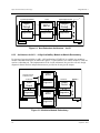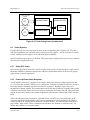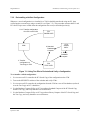
1
Siemens Energy & Automation, Inc. Safety Manual CGQLSAFETY-1 Rev. 8 September 2004 Safety Manual for QUADLOG® Version 3.32 or Higher #Notes CGQLSAFETY-1 Contents Table of Contents Section Title 1.0 1.1 1.2 1.3 1.4 1.5 Introduction....................................................................................................................1-1 Definitions ....................................................................................................................1-1 Scope of Application ....................................................................................................1-2 Suitable Usage ..............................................................................................................1-2 Product Support ............................................................................................................1-4 Related Literature .........................................................................................................1-6 2.0 2.1 2.2 2.2.1 2.2.2 2.2.2.1 2.2.3 2.2.3.1 2.2.3.2 2.2.3.3 Requirements for a SIS Needing TÜV Approval........................................................2-1 General Requirements ..................................................................................................2-1 Functional Requirements ..............................................................................................2-1 Functional Requirements for all Applications .......................................................2-1 Functional Requirements for Fire and Gas Applications .......................................2-4 EN 54 Part 2 .................................................................................................2-5 Guidelines for Usage in Fire and Gas Applications...............................................2-6 Inputs............................................................................................................2-6 Outputs .........................................................................................................2-6 Auto-Shutdown ............................................................................................2-6 3.0 3.1 3.2 3.3 3.4 3.5 3.6 Safety and Functional Safety ........................................................................................3-1 Safety Philosophy .........................................................................................................3-1 Program Separation ......................................................................................................3-2 Communications Separation.........................................................................................3-2 The Project Team..........................................................................................................3-2 Safety Management ......................................................................................................3-3 SIS Documentation Requirements................................................................................3-3 4.0 4.1 4.2 The Safety Life Cycle.....................................................................................................4-1 Safety Life Cycle Steps ................................................................................................4-1 SIS Application Scope Requirements...........................................................................4-1 5.0 Process Design And Hazard Analysis ..........................................................................5-1 6.0 6.1 6.2 6.2.1 6.2.2 6.3 6.4 6.4.1 6.4.1.1 6.4.1.2 6.4.2 6.4.2.1 6.4.2.2 Safety Instrumented System Design.............................................................................6-1 Determining Safety Classes Of the Process..................................................................6-1 Architectures For AK 1 - 4 ...........................................................................................6-1 Architecture for AK 1 - 4 : Non-Redundant (1oo1D)............................................6-1 Architecture for AK 1 – 4 High Availability: Module-to-Module Redundancy....6-2 Architectures for AK 1 - 6: Rack-to-Rack Redundancy (1oo2D) ................................6-3 Field Instrumentation....................................................................................................6-3 Single Sensor Architectures ...................................................................................6-4 Single Sensors – Discrete .............................................................................6-4 Single Sensors – Analog ..............................................................................6-5 Multiple Sensor Architectures................................................................................6-6 Dual Sensors – Discrete ...............................................................................6-6 Dual Sensors – Analog .................................................................................6-7 September 2004 Page i Contents CGQLSAFETY-1 6.4.2.3 6.4.2.4 6.4.3 6.4.4 6.4.4.1 6.4.4.2 6.4.4.3 6.5 6.5.1 6.5.2 6.5.3 6.6 6.6.1 6.6.2 6.6.3 6.6.4 6.6.5 6.6.5.1 6.7 6.7.1 6.7.2 6.7.3 6.7.4 6.8 6.8.1 6.8.2 6.8.3 6.9 6.10 6.11 6.11.1 6.11.2 6.11.3 6.12 6.12.1 6.12.2 6.12.3 6.12.4 6.13 6.13.1 6.14 Triple Sensors – Discrete .............................................................................6-8 Triple Sensors – Analog ...............................................................................6-9 Valve Architectures..............................................................................................6-10 QUADLOG Implementation Examples ...............................................................6-11 Example 1 – Four Safety Instrumented Functions .....................................6-11 Example 2 – Numerous Safety Instrumented Functions ............................6-12 Example 3 – Using SAM and VIM for Critical Analog Inputs..................6-14 Power Systems............................................................................................................6-15 Safety PLC Power................................................................................................6-15 Power-Up/Power-Down Response.......................................................................6-15 Field I/O Power....................................................................................................6-16 Specification of I/O Signals........................................................................................6-16 I/O Voting Function Blocks .................................................................................6-19 Single Source Outputs..........................................................................................6-19 Module Error Status Outputs ...............................................................................6-19 IOBUS Fiber Optic Interface (IFI).......................................................................6-19 Critical Analog Input, Programmable Limits (CAIP) Channel Type ..................6-20 Additional Program Logic Guidelines for Safety Critical Channels..........6-20 Shutdown Logic..........................................................................................................6-21 How the Default Shutdown Logic Works............................................................6-21 Total I/O Shutdown Function Block (TOT_IOSD) .............................................6-23 Shutdown Groups.................................................................................................6-25 Partial I/O Shutdown Function Block (PARTIOSD)...........................................6-26 Maintenance Overrides...............................................................................................6-28 TÜV Maintenance Override Criteria ...................................................................6-28 Forcing of I/O Points............................................................................................6-28 Forced I/O Alarm .................................................................................................6-28 Security.......................................................................................................................6-29 Secured Write Area ....................................................................................................6-31 System Timing............................................................................................................6-31 Input Timing Considerations................................................................................6-32 Diagnostic Timing Considerations.......................................................................6-32 Controller Scan Rate Considerations ...................................................................6-33 Language Operation ...................................................................................................6-35 Math Function Block Characteristics...................................................................6-35 General Function Block Configuration Characteristics .......................................6-36 CCMx Function Block Characteristics ................................................................6-36 Sequential Function Chart Characteristics ...........................................................6-38 Fail Safe Communication (FSC) Function Blocks .....................................................6-38 Safety Critical Communications Guidelines ........................................................6-38 Guidelines For Using QUADLOG Safety Matrix For Safety Critical Functions.......6-39 7.0 7.1 7.2 7.2.1 7.2.2 7.2.3 7.3 ii Installation, Commissioning, and Acceptance Test ....................................................7-1 Installation ....................................................................................................................7-1 Commissioning.............................................................................................................7-1 Transferring the Configuration to the Control Module..........................................7-1 Forcing Variables...................................................................................................7-2 Un-forcing Variables..............................................................................................7-3 Configuration Verification ...........................................................................................7-3 September 2004 CGQLSAFETY-1 Contents 7.3.1 7.3.2 7.4 7.5 7.6 7.7 Saving and Verifying a Configuration ...................................................................7-4 Re-installing a Verified Configuration...................................................................7-5 Acceptance Test............................................................................................................7-6 Activating Secure Mode ...............................................................................................7-6 Software Version Compatibility ...................................................................................7-6 I/O Loop OK Functionality Test for CDO in a 1oo2D System ....................................7-7 8.0 8.1 8.1.1 8.1.2 8.1.3 8.1.4 8.2 8.3 8.3.1 8.3.2 8.3.3 Operation and Maintenance Planning .........................................................................8-1 Operating and Maintaining a Safe System ...................................................................8-1 Module Light Emitting Diodes (LEDs) .................................................................8-1 4-mation Module Tree ...........................................................................................8-1 Diagnostic Logger..................................................................................................8-2 Custom HMI Diagnostic Displays .........................................................................8-2 Management of Change................................................................................................8-2 Security.........................................................................................................................8-3 Activating Security ................................................................................................8-3 Disabling Security..................................................................................................8-3 On-line Configuration Editing ...............................................................................8-3 List of Tables Table Title Page Table 1–1 Technical Support Center Contact Information .......................................................................1-5 Table 2–1 Safety-Related Function Blocks ..............................................................................................2-3 Table 2–2 Safety-Related Ladder Logic Language Elements...................................................................2-4 Table 2–3 Safety-Related Sequential Function Chart Language Elements ..............................................2-4 Table 3–1 Safety Integrity Levels.............................................................................................................3-1 Table 6–1 Safety Classifications...............................................................................................................6-1 Table 6–2 Diagnostic Fault Detection Times .........................................................................................6-34 Table 6–3 Differences in Function Block Outputs Under Certain Conditions .......................................6-37 September 2004 iii Contents CGQLSAFETY-1 List of Illustrations Figure Title Page Figure 1–1 Scope of SIS ...........................................................................................................................1-3 Figure 6–1 Non-Redundant Architecture - 1oo1D....................................................................................6-2 Figure 6–2 Module-to-Module Redundancy.............................................................................................6-2 Figure 6–3 Rack-to-Rack Redundant Architecture - 1oo2D.....................................................................6-3 Figure 6–4 Single Discrete Sensor Architecture 1 with SRSA.................................................................6-4 Figure 6–5 Analog Sensor Architecture 1.................................................................................................6-5 Figure 6–6 Critical Transmitter Architecture............................................................................................6-5 Figure 6–7 Dual Discrete Sensor Architecture .........................................................................................6-6 Figure 6–8 Dual Analog Sensor Architecture 1........................................................................................6-7 Figure 6–9 Dual Critical Transmitter Architecture...................................................................................6-7 Figure 6–10 Triple Discrete Sensor Architecture 1 ..................................................................................6-8 Figure 6–11 Triple Discrete Sensor Architecture 2 ..................................................................................6-8 Figure 6–12 Triple Analog Sensor Architecture 1....................................................................................6-9 Figure 6–13 Triple Analog Sensor Architecture 2....................................................................................6-9 Figure 6–14 Valve Architecture 1...........................................................................................................6-10 Figure 6–15 Valve Architecture 2...........................................................................................................6-10 Figure 6–16 I/O Channel Distribution for Example 1 ............................................................................6-12 Figure 6–17 I/O Channel Distribution for Example 2 ............................................................................6-13 Figure 6–18 Analog Sensor Architecture................................................................................................6-14 Figure 6–19 Dual Analog Sensor Architecture 2....................................................................................6-15 Figure 6–20 Configuration Screen for Power Start-Up Options.............................................................6-16 Figure 6–21 I/O Channel Table Dialog Box ...........................................................................................6-17 Figure 6–22 Softlist Dialog Box .............................................................................................................6-18 Figure 6–23 Default Shutdown Logic.....................................................................................................6-22 Figure 7–1 Using Two PCs to Save and Verify a Configuration..............................................................7-4 Figure 7–2 Using Two PCs to Re-install and Verify a Configuration ......................................................7-5 SIGNIFICANT CHANGES FOR REVISION 8 6.0 Safety Instrumented System Design: 6.14 Guidelines For Using QUADLOG Safety Matrix For Safety Critical Functions • iv Updated notes seven and nine. September 2004 CGQLSAFETY-1 1.0 Introduction Introduction This Safety Manual provides information used to design, program, verify, and maintain a safely operating Safety Instrumented System (SIS) utilizing a QUADLOG safety PLC. The information in this manual has been reviewed and approved by TÜV as part of the type certification process. It is the definitive document for resolving safety-related issues in systems requiring TÜV class approval. This Manual consists of the following sections: • Section 1 – Introduction • Section 2 – Requirements for a SIS Needing TÜV Approval • Section 3 – Safety and Functional Safety • Section 4 – The Safety Life-Cycle • Section 5 – Process Design and Hazard Analysis • Section 6 – Safety Instrumented System Design • Section 7 – Installation, Commissioning, and Acceptance Test • Section 8 – Operation and Maintenance Planning 1.1 Definitions This section defines a list of terms used in this document. Communications Firewall – A combination of software and hardware designed to prevent dangerous failures caused by MODULBUS or MODBUS communications faults. Dangerous Fault – A fault that prevents a discrete input or output from being turned off (de-energized) or causes an analog signal to drift beyond ±2% of its intended value. Degraded Mode – A state in which a Programmable Electronic System (PES) detects a fault in one set of electronics. Fault Detection Time – The maximum time to detect a single dangerous fault. Limit Risk – The largest risk specific to the plant which can continue to be tolerated for a defined technical process or state. In general, limit risk cannot be specified directly as a statement of probability. It is, in general, defined by means of stipulations of technical safety which are made in the light of prevailing technical opinion in accordance with the objectives of the legislative authorities in regard to safety (DIN VDE 31004). Periodic Switch Over Time – The programmed time duration that a Critical Control Module (CCM) stays in Calculate Mode before switching to Verify Mode. PES – Acronym for Programmable Electronic System. September 2004 1-1 Introduction CGQLSAFETY-1 Probability of Failure on Demand (PFD) – The probability that a Safety Instrumented System (SIS) will not perform its preprogrammed action during a specified time interval. This interval of time is typically between periodic inspections. Process Safety Time – A process characteristic specifying the amount of time it takes for process operating conditions to change from safe to dangerous. Risk – An assessment of the frequency of occurrence and severity of harm. RUN mode – The normal operating mode of a QUADLOG controller when it executes its configuration. Safe Fault – A fault that does not prevent an input or output from being turned off (de-energized). Safety – 1. A state in which the risk is not greater than the limit risk (DIN VDE 31000 part 2/12.87). 2. Freedom from unacceptable risks or harm (IEC Guide 51). Safety Accuracy – The accuracy of an analog signal within which the signal is guaranteed to be free of dangerous faults. If the signal drifts outside of the safety accuracy, it is declared faulty. Safety Availability – The probability that a Safety Instrumented System (SIS) will perform its preprogrammed action during time periods of normal process operation. Safety Availability = 1 – PFD. Safety Instrumented Function – A logical grouping of functions that perform a single function. Also known as a safety loop. Shutdown State – A state where outputs are de-energized. SIS – Acronym for Safety Instrumented System. STOPPED mode – A QUADLOG controller mode in which the controller stops configuration execution, but still communicates with its MODULBUS and IOBUS networks. 1.2 Scope of Application The QUADLOG Safety PLC is a programmable electronic system (PES) for use in automated Safety Instrumented Systems (SIS). The illustration in Figure 1-1 defines the boundaries of the PES and the SIS and identifies the devices that may be included in the system. The SIS is the portion enclosed by a dotted line. 1.3 Suitable Usage QUADLOG equipment can be used in a large variety of applications. The user and those responsible for applying this equipment must ensure the acceptability of each application and the use of the equipment. 1-2 September 2004 CGQLSAFETY-1 Introduction DCS HM I Safety PL C A ctuators Sensors S afety Instrum ented System Figure 1–1 Scope of SIS The SIS includes all elements from the sensor to the final element, including inputs, outputs, power supply, and logic solvers. Other interfaces to the SIS are considered a part of the SIS if they have potential impact on its safety function. September 2004 1-3 Introduction 1.4 CGQLSAFETY-1 Product Support Product support can be obtained from a Technical Support Center (TSC). Each regional TSC is a customer service center that provides direct telephone support on technical issues related to the functionality, application, and integration of all products supplied by Siemens. Regional TSC contact information is provided in Table 1–1. Your regional TSC is the first place you should call when seeking product support information. When calling, it is helpful to have the following information ready: • Caller name and company name • Product part number or model number and version • If there is a problem with product operation: - Whether the problem is intermittent - The steps performed before the problem occurred - Any error messages or LED indications displayed - Installation environment Product documentation is now located in the Library forum of the Process Automation User Connection at: http://sitescape.sea.siemens.com/. The Process Automation User Connection is a secure site. Registration is open to all verified users of Siemens process automation systems. If you are not already, and would like to become a member, please visit our Process Automation User Connection web page at: http://www.sea.siemens.com/process/support/papauc.html Contained within the Process Automation User Connection is the APACS+/QUADLOG Secure Site at: http://sitescape.sea.siemens.com/forum/aca-1/dispatch.cgi/f.apacsquadlo forum. This site is only open to customers with an active service agreement. It contains all service manuals, service memos, service notes, configuration manuals, etc. for the APACS+ and QUADLOG family of products. If you are experiencing technical difficulties with the site, please contact SiteScape technical support at: toll free 1-877-234-1122 (US) or 1-513-336-1474. 1-4 September 2004 CGQLSAFETY-1 Introduction Table 1–1 Technical Support Center Contact Information NORTH AMERICA Tel: +1 215 646 7400, extension 4842 Fax: +1 215 283 6343 E-mail: Hours of Operation: Secure Web Site: ASIA www.sea.siemens.com/process/product/papao.html +011 65 740 7818 Fax: +011 65 740 7817 E-mail: Secure Web Site: [email protected] 8:30 a.m. to 5:30 p.m. Singapore time Monday – Friday (except holidays) www.siemens.com Tel: +44 (0) 1905 450930 Fax: +44 (0) 1905 450931 E-mail: Hours of Operation: Secure Web Site: September 2004 8 a.m. to 5 p.m. eastern time Monday – Friday (except holidays) Tel: Hours of Operation: EUROPE [email protected] [email protected] 8:30 a.m. to 4:30 p.m. GMT/BST Monday – Friday (except holidays) www.siemens.com 1-5 Introduction 1.5 CGQLSAFETY-1 Related Literature The following documentation is required to safely design, install, configure, and maintain a QUADLOG safety system: Configuration Documents • ProcessSuite, 4-mation, Installation, Configuration and Operation User’s Manual (binder number UM39R4-11V3.00) • ProcessSuite, 4-mation, Function Block Language User’s Manual (binder number UM39R4-12V3.00) • ProcessSuite, 4-mation, Ladder Logic, SFC and ST Languages User’s Manual, (binder number UM39R4-13V3.00) • ProcessSuite, 4-mation, Configuring APACS+ and QUADLOG Hardware User’s Manual, (binder number UM39R4-14V3.00) Hardware Documents • QUADLOG, Control and I/O Modules User’s Manual, (binder number UMQL-1) • QUADLOG, Communication and Computer Hardware User’s Manual, (binder number UMQL-2) • APACS+/QUADLOG Packaging and Power Module User’s Manual, (binder number UM39R4-5) Standards and Guidelines • Application of Safety Instrumented Systems for the Process Industries (Document # S84.01) Instrument Society of America (ISA) 67 Alexander Drive P.O. Box 12277 Research Triangle Park, NC 27709 • Safety Shutdown Systems: Design, Analysis and Justification, Gruhn & Cheddie, ISA, 1998, ISBN 155617-665-1 • Control System Safety Evaluation and Reliability, 2nd Edition (Document # ISBN# 1-55617-638-8, ISA, 1998) • Functional Safety of Electrical/Electronic/Programmable Electronic Safety-Related Systems (Document # IEC61508) • Guidelines for the Safe Automation of Chemical Processes (Document # ISBN 0-8169-0554-1) American Institute of Chemical Engineers (AIChE) 345 E. 47th Street New York, NY 10017 1-6 September 2004 CGQLSAFETY-1 Introduction • Functional Safety: – Fundamental Safety Aspects to be Considered for Measurement and Control Equipment (Document # DIN V 19250:1994) – Principles for Computers in Safety-related Systems, Requirement Class AK 1-6 [Document # DIN V VDE 0801:1990 (including Annex A1:1994)] – Quality Assurance Manual of IQSE [Document # QSH IQSE (Version 1.1)] – Components of Automatic Fire Detection Systems, Control and Indicating Equipment (Document # DIN EN 54-2:1990, Part 2 (to the extend applicable) • Basic Safety: – Safety Requirements for Electrical Equipment for Measurement, Control and Laboratory Use, Part 1: General Requirements (Document # EN 61010-1:1993) – Environmental Testing, Test Ab: Cold (-25ºC 96 hr) (Document # IEC 68, Part 2-1:1985) – Environmental Testing, Test Ab: Cold (-25ºC 16 hr) (Document # IEC 68, Part 2-1:1985) – Environmental Testing, Test Ab: Cold (0º C 16 hr) (Document # IEC 68, Part 2-1:1985) – Environmental Testing, Test Bb: Dry Heat (70ºC 96 hr) (Document # IEC 68, Part 2-2: 1980) – Environmental Testing, Test Bb: Dry Heat (60ºC 16 hr) (Document # IEC 68, Part 2-2:1980 – Environmental Testing, Test Na: Temperature Change (-25ºC 3.5 hr change to 70ºC ,3 min. 2 times) (Document # IEC 68, Part 2-14: 1987) – Environmental Testing, Test Nb: Temperature Change (5ºC 3 hr change to 40ºC 3.5 hr @ 3ºC/min. 5 cycles (Document # IEC 68, Part 2-14:1987) – Environmental Testing, Test Db: Damp Heat, Cyclic Test (25ºC 12 hr change to 55ºC 95%RH 12 hr 2 cycles) (Document # IEC 68, Part 2-30:1986) – Environmental Testing, Test Ca: Damp Heat, Steady-State (40ºC 93%RH 96 hr) (Document # IEC, Part 2-30: 1986) – Environmental Testing, Test Fc: Vibration, Sinusoidal (Document # IEC, Part 2-6:1990) – Environment Testing, Test Ea: Shock (Document # IEC, Part 2-27:1989) September 2004 1-7 CGQLSAFETY-1 • Electromagnetic Compatibility: – Immunity, Electrostatic Discharge (ESD) [Document # EN61000-4-2 (formerly IEC 801-2)] – Immunity, Electrical Fast Transient (EFT) [Document # EN61000-4-4 (formerly IEC 801-4)] – Immunity, Radiated Electromagnetic Field (RFI) [Document # EN61000-4-3 (formerly IEC 801-3)] – Immunity, Surge (Document # EN61000-4-5) – Immunity, Conducted Electromagnetic Field (RFI) [Document # EN61000-4-6 (formerly IEC 801-6) ] – Emissions, Conducted (Document # EN55011) – Emissions, Radiated (Document # EN55011) • Product-Related Quality Assurance and Certification: – Guideline for the Selection and Use of Standards on Quality System Elements and Quality Assurance (Document # DIN ISO 9001:1994) – Quality Assurance Manual of IQSE [Document # QSH IQSE (Version 1.1)] 1-8 September 2004 CGQLSAFETY-1 2.0 Requirements for a SIS Needing TÜV Approval Requirements for a SIS Needing TÜV Approval The QUADLOG system can be used within a Safety Instrumented System (SIS) for those processes that require TÜV approval. The requirements presented in this section must be met when designing such a system. 2.1 General Requirements The SIS response time must be less than the process safety time. The SIS response time must include the response times of sensors, logic solver, and final elements in the safety function. The logic solver time includes I/O processing and the controller scan rate. Since QUADLOG I/O processing occurs asynchronously to the controller on independent modules, the input and output modules contribute a separate portion to the logic solver response time. The control module’s scan rate must be set to the appropriate time. For details on determining a controller scan rate, see section 6.11.3. All PES components must be fully operational before process start-up. All error codes must be cleared. If the PES detects faults in field wiring or in other areas, they must be repaired before start-up. Changes to the logical configuration can only be implemented when there are sufficient organizational measures established to insure the safety of the process. In those processes where the process safety time is too short to allow for human intervention, on-line logical configuration changes must not be permitted. In a QUADLOG system, enabling its security function during safety operation prevents on-line configuration changes. When security is enabled, configuration changes and changes such as forcing I/O values are not permitted. For security details, refer to section 6.9. 2.2 Functional Requirements The following requirements must be met when designing a SIS using a QUADLOG safety system for processes that require TÜV approval: 2.2.1 Functional Requirements for all Applications • QUADLOG installation and test procedures must be followed (refer to section 7.0 ). • QUADLOG operation and maintenance procedures must be followed (refer to section 8.0 ). • Certified configuration language components must be used to process safety critical signals and functions. TÜV has certified the operation of the following IEC 61131-3 language functions as safety-related: - Function Blocks - Ladder Logic - Sequential Function Charts The safety-rated elements of these languages are listed in Table 2–1 through Table 2–3 respectively. September 2004 2-1 Requirements for a SIS Needing TÜV Approval • CGQLSAFETY-1 The following software components are certified as "interference-free." These software components can be used within a safety system for non-safety or control functions: - Interference free module operating software - Real-time functions in QUADLOG SET (System Engineering Tool) (except forcing) - Select QUADLOG SET language elements: - Specific function blocks that are not certified as safety-rated, such as PID Controller blocks - Structured text - Dynamic array indexing with variables IMPORTANT When configuring a safety system, certain outputs on the following function blocks should not be used to drive physical outputs. These output values could differ between Calculate and Verify controllers in a redundant configuration, resulting in output mismatches and system shutdown. [System Service Code (SSC) 27, Error Code (EC) 47 or SSC 18, EC 63]. FUNCTION BLOCKS OUTPUTS ERR_LOG All (use SYSINFO Function Block instead) MEMSTAT All MODINFO All TOT_IO, PART_IO, TOT_IOSD, and PARTIOSD SCANTM and ERRCOD For the following function blocks in QUADLOG system software prior to ACM+/CCM Version 3.30, the listed outputs apply: 2-2 RED_SD OUT and EN_OUT RSCCTRL CLASS4 TOT_IO and PART_IO CLASS4 September 2004 CGQLSAFETY-1 Requirements for a SIS Needing TÜV Approval Table 2–1 Safety-Related Function Blocks FUNCTION BLOCK CLASS Math Calculations Dynamic Diagnostic FUNCTION BLOCK NAME ABS (Absolute Value) ADD (Addition) DIV (Division) MUL (Multiplication) SCALER (Scaler) SQRT (Square Root) SUB (Subtraction) FILTER (Filter-1st Order Lag) ANVOTER (Analog Voter) FUNCTION BLOCK CLASS Shift and Rotate Move Timing AN1OO2D (1oo2D Analog Voter) Compare and Select BLVOTER (Boolean Voter) EQ (Equal) NE (Not Equal) GT (Greater Than) GE (Greater Than or Equal) LT (Less Than) LE (Less Than or Equal) SEL (Selector) MIN (Low Selector) MID_SEL (Middle Selector) MAX (High Selector) LIMIT (Limiter) MUX (Multiplexer) CDSI (Critical Discrete Supervised Input) Logic Function September 2004 FUNCTION BLOCK NAME SHL (Shift Left) SHR (Shift Right) ROL (Rotate Left) ROR (Rotate Right) MOVE (Data Move) SET_VAL (Set Value) TON (On Timer) TOF (Off Timer) ROT (RetentiveTimer) TP (Timed Pulse) REPCYCL (Repeat Cycle Timer) Counting Resource CTU (Up Counter) CTD (Down Counter) CTUD (Up/Down Counter) RSCCTRL (Resource Control) TOT_IOSD (Total I/O Scan and Shutdown PARTIOSD (Partial I/O Scan and Shutdown) QL_SECR (Security) Fail Safe Communications FSC SND FSC REC Quality QUALBAS QUAL_CK S_MTRX_32x32 S_MTRX_128x128 Safety Matrix (UDFB) Sequential Function Chart (SFC) CHRTMOD (SFC Chart Mode Control FB) AND (Logical AND) OR (Logical OR) XOR (Logical Exclusive OR) NOT (Logical NOT) SR Flip-Flop (Set Reset) RS Flip-Flop (Reset Set) R_TRIG (Rising Edge Trigger) F_TRIG (Falling Edge Trigger) 2-3 Requirements for a SIS Needing TÜV Approval CGQLSAFETY-1 Table 2–2 Safety-Related Ladder Logic Language Elements LADDER LOGIC CLASS Link Element ELEMENT NAME H shunt (Horizontal Shunt) V shunt (Vertical Shunt) Contact NOC (Normally Open Contact) NCC (Normally Closed Contact) PTC (Positive Transition Contact) NTC (Negative Transition Contact) Coil Set (Latch) Coil Reset (Unlatch) Coil Retentive (Memory) Coil Set Retentive Coil Reset Retentive Coil Positive Transition Sensing Coil Negative Transition Sensing Coil Negated Coil Table 2–3 Safety-Related Sequential Function Chart Language Elements SEQUENTIAL FUNCTION CHART CLASS Step Transition Action Element Action Qualifier 2.2.2 ELEMENT NAME Initial Step Step Transition Boolean Non-Boolean N (Non Stored) S (Set Stored) R (Overriding Reset) P (Pulse) L (Time Limited) SL (Stored and Time Limited) D (Time Delayed) SD (Stored and Time Delayed) DS (Delayed and Stored) Functional Requirements for Fire and Gas Applications With reference to the standard EN 54: Fire detection and alarm systems - Part 2: Control and indicating equipment, additional measures have to be taken as stated below: • 2-4 Where inputs are energized to annunciate a problem, the QUADLOG system must be configured to detect and alarm both open and short circuits in the wiring between the field devices and the QUADLOG termination strips. September 2004 CGQLSAFETY-1 Requirements for a SIS Needing TÜV Approval • Fire detection and alarming systems require a minimum of dual power supplies with dual independent feeders. When independent feeders are unavailable at least one of these feeders shall be from an uninterruptible power supply (UPS). • The safety system may use normally de-energized outputs. The outputs are energized to initiate action to mitigate a problem. Output channels on CDMs and CDOs must have output monitoring diagnostics enabled using the Pulse Test softlist parameter. These diagnostics detect open wiring faults to output devices. 2.2.2.1 EN 54 Part 2 With specific reference to clauses from EN 54 Part 2, the following unambiguous measures have to be taken: • 5.1.2 For multiple sensors in one fire zone, independent input channels on at least two different input modules are necessary. Complementary outputs, such as general visual and audible alarm versus zone alarm, shall be on at least two different output modules. • 7.1.5 The application has to be built such that no multiple fire signals can result from the simultaneous operation of two points. This can be achieved e.g. by means of “m out of n”-voting. • 8.2.4 Line faults and system faults, the latter represented by the REPAIR -output of the ‘Total IO Shutdown’ function block (common alarm), are processed by the application. The REPAIR output value of the Total I/O Shutdown function block shall be continuously monitored for the presence of a fault. This can be easily implemented using an alarm function in the HMI. • 8.4 The system shall monitor the standby power and an alarm shall be sent to the operator. • 8.5 The degradation and system shutdown must be indicated by visible and audible alarm via a safetyrated output board and inverter relays. • 8.8 Use of de-energized to trip output boards with inverter relays when needed. • 8.9 The contact side of the inverter relay needs to be loop monitored. • 12.3.1 The cabinet shall meet at least IP30. • 13.5.3d Only systems with redundant logic solvers (minimum 1oo1D with redundant CCMs) shall be used. Use of redundant I/O is optional. • 13.7 The size of a sub system (CCM-pair) shall remain less than 512 total fire detectors and/or manual call points. September 2004 2-5 Requirements for a SIS Needing TÜV Approval 2.2.3 CGQLSAFETY-1 Guidelines for Usage in Fire and Gas Applications For conformance to the EN 54 standard, it is recommended that the following QUADLOG modules (all certified as “safety-rated”) be used for a fire detection and alarm system: • • • • • CCM (Critical Control Module) CAI (Critical Analog Input Module) CAM (Critical Analog Module) CDM (Critical Discrete Module) CDO (Critical Discrete Output Module) Refer to the individual module Installation and Service Instruction manuals. Different field instrument configurations may be used for each detection zone. It is the responsibility of the system designer to verify that field instrumentation is acceptable for each zone, points, addressable points and/or fire alarm devices per QUADLOG system. 2.2.3.1 Inputs Many fire detection and alarm applications utilize the ability to connect multiple detectors or manual call points to a single input channel. The QUADLOG system supports this connectivity, but limits the maximum quantity to less than thirty-two detectors per input channel. Since variations in the length and type of wiring, and manufactured detector differences, calculations are to be performed by the system designer to determine the maximum quantity of devices allowed per channel. These calculations should be compared to the specified operating parameters for the Critical Discrete Supervised Input (CDSI) function block (see the online FB help file). The CDSI function block and the CDSI channel type should be used for “energized-to-trip” discrete inputs. The CDSI function block is certified to accurately monitor and detect fault conditions. The channel is designed to be used with the contactor elements of fire detection devices. 2.2.3.2 Outputs Critical output channels for fire detection and alarming applications are typically configured as normally de-energized. To meet output channel requirements, configure each output channel of a CDM or CDO module so its pulse testing function is enabled. This function checks the channel for specific types of line faults. The protected output and shutdown softlist parameters for each configured output channel should be disabled to prevent potentially dangerous false trips. For additional information about configuring CDM or CDO output channels, refer to the Module Installation and Service Instructions and I/O Module Configuration Guide (document number CGQL-4). 2.2.3.3 Auto-Shutdown For fire alarming and detection applications, the auto shutdown (AUTO_SD) input of the Total I/O Shutdown (TOT_IOSD) function block (or the Partial I/O Shutdown block) should be changed from its default value of TRUE to FALSE. This change prevents the automatic system shutdown (all outputs turned off) resulting from the emergence of any shutdown-level (class 4) error on the control module or any of its scanned I/O modules. This change is imperative due to the nature of fire detection and alarming applications operating in the normally de-energized (energized-to-trip) mode. 2-6 September 2004 CGQLSAFETY-1 3.0 Safety and Functional Safety Safety and Functional Safety Safety has been defined as the freedom from unacceptable risk of harm. There is risk in the operation of many industrial processes. In many cases, the risk must be reduced. A Safety Instrumented System (SIS) is one of the tools that can be used by a process control engineer to reduce risk in an industrial process. The SIS is designed to automatically respond to potentially dangerous process conditions and take preprogrammed action to mitigate or avoid a dangerous condition. The QUADLOG safety PLC is designed to be part of a SIS. Safety is measured primarily by a parameter called Average Probability of Failure on Demand (PFDavg). This is a probability number ranging between zero and one. This indicates the chance that a SIS will not perform its preprogrammed action during a specified interval of time (usually the time between periodic inspections). A related measure is called Safety Availability. It is defined as the probability that a SIS will perform its preprogrammed action when the process is operating. It can be calculated as follows: Safety Availability = 1 - PFDavg Another parameter is called the Risk Reduction Factor (RRF). It represents the ratio of risk without a SIS divided by the risk with a SIS. It can be calculated as follows: RRF = 1 PFDavg The amount of risk reduction needed for an industrial process must be determined. This is usually done by classifying each safety instrumented function according to an order of magnitude scale. This scale is called Safety Integrity Levels (SIL). These are specified in the ISA S84.01 standard and in the IEC61508 standard (see section 4.0 for references). Table 3-1 shows the target range of values. The values apply to the entire set of equipment for each safety instrumented function including process connections, sensors, QUADLOG, and actuator/valves. Table 3–1 Safety Integrity Levels SAFETY INTEGRITY LEVEL 4 3 2 1 3.1 PFDavg SAFETY AVAILABILITY < 0.0001 0.001 –0.0001 0.01 – 0.001 0.1 – 0.01 >0.9999 0.999 – 0.9999 0.99 – 0.999 0.9 – 0.99 RISK REDUCTION FACTOR >10,000 1,000 – 10,000 100 – 1,000 10 - 100 Safety Philosophy A SIS must be designed in a systematic manner as part of an overall safety program. The safety life-cycle approach should be used in the implementation of such systems. Organizational responsibilities for each life cycle task must be assigned. Checklists should be used to assure that all necessary tasks are completed. September 2004 3-1 Safety and Functional Safety CGQLSAFETY-1 QUADLOG is programmed using the 4-mation configuration software. 4-mation provides languages from the IEC 1131-3 international standard. QUADLOG configuration should be done in a systematic manner with complete testing of each portion of the configuration. 3.2 Program Separation The safety-related portion of the configuration should be separated from the non-safety-related portion of the configuration. The 4-mation configuration software supports the development of hierarchical or object-oriented configurations for QUADLOG control modules. Every control module configuration has a top-level sheet known as the resource sheet where control module options are configured. Additionally, program blocks are created and placed on this sheet to define the major sections of the configuration. Program blocks allow for clear distinction between the safety-related and non-safety-related sections of the application program. 3.3 Communications Separation The communication between QUADLOG control modules and QUADLOG I/O modules takes place over the redundant QUADLOG IOBUS. IOBUS communications is safety-related since control and I/O modules use it to exchange safety-critical input and output information. The IOBUS can be extended locally or remotely from its corresponding control module using standard IOBUS cables and/or fiber optic cable. It can connect multiple I/O racks including UNIRACs, Remote I/O Racks, SIXRACs or MODULRACs. Inter-processor communications, which transfers configuration and status information between redundant control modules, is also safety related. Failsafe communication Function Blocks should be used when exchanging safety critical data between QUADLOG controllers via MODULBUS or MODULNET. Non-safety critical data may be exchanged between safety and non-safety systems using standard MODULBUS and MODULNET implementation. Safety critical inputs and outputs should be hardwired to QUADLOG safety certified I/O modules. 3.4 The Project Team Typically, the project team responsible for the design, installation, and start-up of a Safety Instrumented System consists of the following personnel: • Control Engineer • Programmer • Installer • Commissioner 3-2 September 2004 CGQLSAFETY-1 Safety and Functional Safety Personnel assigned to the tasks in the safety life cycle shall have the following competencies: • Engineering experience appropriate to the process application area. • Engineering experience and knowledge appropriate to SIS equipment and technology. This knowledge should include failure modes of sensors and actuators, QUADLOG error codes, and QUADLOG maintenance procedures. Siemens Energy & Automation Training Course #20018-39, QUADLOG Configuration and Operations, is recommended for your system’s Control Engineer, Programmer, Installer, and Commissioner. The Control Engineer, Installer, and Commissioner should also take Training Course #20018-32, Building Safe, Reliable Control System. • Safety engineering appropriate to the technologies. • Knowledge of the legal and regulatory environment. Refresher training is recommended and may be required of all involved personnel to ensure their capability. 3.5 Safety Management To achieve a successful installation of a Safety Instrumented System, the installer or owner of the safety system should prepare and follow a safety plan. The safety plan should outline the necessary activities to ensure safe selection, programming, installation, commissioning, operation, and maintenance of the safety system. The structure of the safety plan should follow the life-cycle phases of a safety-system installation. 3.6 SIS Documentation Requirements Documentation shall be produced during the safety life-cycle to sufficiently meet the needs of corporate and applicable standards. This documentation could include: • • • • • • A Safety Plan A Hazard Review A Safety Requirements Specification A Safety Instrumented System Design A Pre-Start-up Acceptance Test Operation and Maintenance Procedures The safety plan is intended for listing the plan of all safety life-cycle activities. The responsibility for each task should be assigned to the appropriate individual. The task list and assignments should be documented. The safety plan could also include cost estimates and schedules. The hazard review contains a systematic review of the process to identify possible hazards. The conditions examined and hazards identified must be documented. The hazard review should also include the effects of a control system failure. A safety requirements specification document must contain the safety requirements of each hazard identified in the hazard review. September 2004 3-3 Safety and Functional Safety CGQLSAFETY-1 The Safety Instrumented System design document details the design of a SIS. Some safety requirements may be met by using a SIS. (In the case of QUADLOG, much of the documentation can be generated using the 4-mation configuration software.) A pre-startup acceptance test (PSAT) should verify that the SIS has successfully met all its assigned safety requirements. This testing should be carefully planned to avoid systematic errors of omission or commission. The test plan and test results must be documented. All actions necessary to properly operate and maintain the SIS must be documented. These procedures should cover on-line testing, management of change, repair procedures, and incident reporting. 3-4 September 2004 CGQLSAFETY-1 4.0 The Safety Life Cycle The Safety Life Cycle The safety life cycle covers the safety instrumented system (SIS) activities from initial conception through decommissioning. 4.1 Safety Life Cycle Steps The safety life cycle involves the following general steps: 1. Perform conceptual process design. 2. Perform process hazard analysis and risk assessment. 3. Apply non-SIS protection layers to prevent identified hazards or to reduce risk. 4. Determine if an adequate number of non-SIS protection layers have been provided. If a SIS is appropriate, establish the requirements for the SIS by defining a target safety integrity level (SIL). 5. Develop safety requirement specifications. 6. Develop the SIS conceptual designs that may meet the safety requirement specifications. 7. Perform detailed design 8. Install the SIS. 9. Perform the commissioning and pre-startup acceptance test (PSAT) of the SIS. 10. Develop SIS operation and maintenance procedures at any step of the safety life cycle, but complete them prior to startup. 11. Perform pre-startup safety review (PSSR) prior to startup of the SIS. 12. Place SIS in operation after PSSR, including start-up, normal operation, maintenance, and periodic functional testing. 13. Perform modifications in accordance with the management of change (MOC) procedure. The appropriate steps in the safety life cycle shall be repeated to address the safety impact of the change. 14. Plan the decommissioning of the SIS and take appropriate steps to ensure that this is accomplished in a manner that does not compromise safety. 4.2 SIS Application Scope Requirements The process engineer defines the exact boundaries of the process equipment under control (EUC) and provides a description sufficient for the necessary understanding of the process and the EUC. September 2004 4-1 The Safety Life Cycle CGQLSAFETY-1 #Notes 4-2 September 2004 CGQLSAFETY-1 5.0 Process Design And Hazard Analysis Process Design And Hazard Analysis After the process design has been completed, potential hazards must be identified and documented. The procedures used for hazard analysis are beyond this document’s scope. Refer to section 1.5, Related Literature, for documentation references pertaining to this topic. September 2004 5-1 Process Design And Hazard Analysis CGQLSAFETY-1 #Notes 5-2 September 2004 CGQLSAFETY-1 6.0 6.1 Safety Instrumented System Design Safety Instrumented System Design Determining Safety Classes Of the Process Every safety-instrumented function (safety protection loop) has to be classified with regard to safety integrity. Classification can be determined by applying corporate standards, industry standards or international standards. If multiple safety-instrumented functions are within one Safety Instrumented System (SIS), the common elements of the SIS, such as logic solver, should meet the highest loop safety class. Safety classifications in accordance with the standard Fundamental Safety Aspects to be Considered for Measurement and Control Equipment (Document # DIN V 19250:1994) are listed in Table 6-1. Table 6–1 Safety Classifications REQUIREMENTS CLASS 1–4 1–4 1–6 QUADLOG ARCHITECTURE Non-redundant – 1oo1D Module-to-Module Redundant - 1oo1D Rack-to-Rack Redundant - 1oo2D NOTE Standard IEC61508 refers to Safety Integrity Levels (SIL) and provides quantitative targets for PFDavg values for each level and application (see section 3.0 “Safety and Functional Safety”). This target refers to the entire safety instrumented function (safety loop) including sensors, logic solver, and valve/actuator. To achieve the required SIL, the entire safety loop from end to end should be considered in a quantitative calculation. The configuration of field instruments (see section 6.4, Field Instrumentation) will have an impact on the quantitative results. Those attempting to comply with IEC61508 should contact Siemens for failure rate information and assistance. 6.2 6.2.1 Architectures For AK 1 - 4 Architecture for AK 1 - 4 : Non-Redundant (1oo1D) The configuration presented in Figure 6–1 (1oo1D) can be used for requirements classes AK 1 - 4. It consists of a dual channel system with a functional channel and a diverse design diagnostic channel that performs self-testing. The diagnostic channel controls the Protected Output™, which provides a secondary means of de-energization. This non-redundant configuration is designed to tolerate any single fault without compromising its ability to safely shut down the process that it is protecting. September 2004 6-1 Safety Instrumented System Design Input/Output Module CGQLSAFETY-1 CCM Input Circuit MPU Diagnostics Diagnostics + Input/Output Module Output Circuit Diagnostics Final Element Sensor Figure 6–1 Non-Redundant Architecture - 1oo1D 6.2.2 Architecture for AK 1 – 4 High Availability: Module-to-Module Redundancy For increased system availability in AK1 - AK4 applications, QUADLOG is available in a module-tomodule redundant architecture as detailed in Figure 6–2. In this scheme, two control modules (CCMs) are used as a redundant pair. This implementation of the 1oo1D architecture also provides a diverse design diagnostic channel and two independent means are provided to de-energize the outputs. CCM INTERPROCESSOR COMMUNICATION MPU I/O Module I/O Module Input Circuit Diagnostics + Output Circuit CCM Diagnostics MPU Diagnostics Final Element Sensor Diagnostics - Figure 6–2 Module-to-Module Redundancy 6-2 September 2004 CGQLSAFETY-1 6.3 Safety Instrumented System Design Architectures for AK 1 - 6: Rack-to-Rack Redundancy (1oo2D) When high availability and safety are required in an application, such as applications requiring TÜV class AK5 - AK6 approval, the rack-to-rack redundant version of QUADLOG, as shown in Figure 6–3, is available. The system is fully fault-tolerant. To ensure high levels of safety, both units shut down in the rare event of an inter-processor comparison mismatch. INTERPROCESSOR COMMUNICATION Input/Output Module CCM Input Circuit MPU Output Circuit Diagnostic Circuit Diagnostic Circuit Diagnostic Circuit Input/Output Module CCM Input/Output Module Input Circuit MPU Output Circuit Diagnostic Circuit Diagnostic Circuit Diagnostic Circuit Sensor + Input/Output Module Final Element Figure 6–3 Rack-to-Rack Redundant Architecture - 1oo2D To meet maximum PFD requirements in AK-5 and AK-6 applications, systems in degraded mode must be repaired within a period of time defined by a maximum probability of failure on demand (PFDavg) calculation done by Siemens for a specific system. The QUADLOG implementation of the 1oo2D architecture employs periodic switching between the calculate and verify sides. This increases diagnostic coverage capabilities especially for multiple fault scenarios. The switch time must be set to a value less than half of the second fault detection time. (Twenty-four (24) hours is recommended for burner management applications under EN298 or calculated number.) The default switching time of four (4) hours is recommended. 6.4 Field Instrumentation SIS design must consider all elements of the system including process connections, sensors, the QUADLOG safety PLC, and actuators/valves. The same design principles (fail-safe design and diagnostics) apply to all areas of the system. Through a variety of I/O modules QUADLOG offers the capability to connect to many kinds of field instrumentation. September 2004 6-3 Safety Instrumented System Design CGQLSAFETY-1 Once the requirements class of each safety instrumented function is determined, the appropriate configuration for sensors and valves can be chosen. Different configurations may be used for each function. It is the responsibility of the system designer to verify that field instrumentation is acceptable for use in each safety instrumented function. It is recommended that the system designers obtain a list of failure modes for each field device used. This is often available from the field instrumentation manufacturer or a corporate database. An analysis of system-level failure modes and effects can be used to identify the effects of these failures. The potentially dangerous failure modes of field instrumentation will require system level design changes or alternative field instrument configurations. Field instrumentation failure rates for each failure mode will also be required to do system-level quantitative safety analysis if that method is used to demonstrate compliance with safety regulations. In AK-5 and AK-6 systems, a redundant 1oo2D architecture is required. A redundant architecture is implied for the Figures in sections 6.4.1 to 6.4.4 when required. QUADLOG supports TÜV-approved safety-critical analog and discrete signals from single sensors. The subsections to follow demonstrate various configuration options using single and multiple sensors 6.4.1 Single Sensor Architectures Using a single sensor for each process measurement is permitted in safety protection applications; however, a careful risk analysis should be done to verify that this configuration meets needed safety. 6.4.1.1 Single Sensors – Discrete Within a QUADLOG system, critical discrete inputs can be connected to the Critical Discrete Module (CDM). The CDM has two versions: 24 VDC and 48 VDC. Figure 6–4 shows a single, discrete sensor (PS = Pressure Switch) wired to a CDM. The wiring includes an optional Safety Related Switch Adapter (SRSA). The SRSA may be installed at the termination strip or at the field sensor. Installation of a SRSA at the field sensor allows the automatic detection of field wiring short-circuit failures. SRSA installation is required for safety-critical signals in TÜV requirements classes AK4 - AK6. The configuration shown in Figure 6-4 is TÜV-approved for these requirements classes. + I/O Power PS I/O POWER - COM + + - IN QUADLOG CCM QUADLOG CDM IOBUS logical signal Discrete Sensor SRSA Figure 6–4 Single Discrete Sensor Architecture 1 with SRSA 6-4 September 2004 CGQLSAFETY-1 Safety Instrumented System Design 6.4.1.2 Single Sensors – Analog Analog sensors offer several advantages in safety protection applications because sensor failure is much easier to detect. . Within a QUADLOG system, critical analog sensors can be connected to a Critical Analog Module (CAM) or a Critical Analog Input Module (CAI). Figure 6-5 shows a single analog sensor (PT = Pressure Transmitter) connected to a CAM. Field wiring is simplified because the CAM provides a built-in power supply for each channel. Open and short-circuit field wiring faults are detected with internal diagnostics. This configuration is approved for safety-critical signals in TÜV approved systems for requirements classes AK4 – AK6. Analog Transmitter 4- 20 mA. + PT - QUADLOG CAM QUADLOG CCM IOBUS Figure 6–5 Analog Sensor Architecture 1 Figure 6-6 shows a similar architecture using a safety-rated transmitter. Safety-rated analog sensors, such as the Siemens Critical Transmitter, significantly improve the safety of a single sensor due to its very low probability of failure upon demand. This configuration is also approved for safety-critical signals in TÜVapproved systems for requirements classes AK4 – AK6. Critical Transmitter 4- 20 mA. + PT - QUADLOG CAM QUADLOG CCM IOBUS Figure 6–6 Critical Transmitter Architecture September 2004 6-5 Safety Instrumented System Design 6.4.2 CGQLSAFETY-1 Multiple Sensor Architectures Often times a single sensor cannot provide a sufficient amount of risk reduction to achieve the necessary probability of failure on demand for the overall safety instrumented function. The following sections describe how dual and triple sensors can be applied to the same process measurement to increase the amount of risk reduction. 6.4.2.1 Dual Sensors – Discrete Figure 6–7 shows a dual, discrete sensor architecture implemented with QUADLOG. This configuration is approved for safety-critical signals in TÜV approved systems for requirements classes AK4 – AK6. SRSAs are recommended in order to implement field wiring diagnostics and are required for TÜVapproved systems in requirements classes AK4-AK6. A Boolean Voter function block is available for 1oo2 functionality (see section 6.6.1 for descriptions of Voter function blocks). Discrete Sensor + + PS - SRSA - QUADLOG CDM QUADLOG CCM + - Discrete Sensor logical signals IOBUS + PS - Boolean Voter Block SRSA Figure 6–7 Dual Discrete Sensor Architecture 6-6 September 2004 CGQLSAFETY-1 Safety Instrumented System Design 6.4.2.2 Dual Sensors – Analog Using dual analog sensors for each process measurement reduces risk especially with sensors that are not specifically designed for fail-safe operation. There are several ways to implement dual analog sensors with QUADLOG. Figure 6–8 shows dual analog sensors connected to a Critical Analog Module (CAM). This configuration is allowed for safety-critical signals in systems needing TÜV approval for requirements classes AK4-AK6. The Critical Analog Input Module (CAI) used in a similar fashion. Analog Transmitter 4- 20 mA. PT + - QUADLOG CAM QUADLOG CCM Analog Transmitter 4- 20 mA. + PT IOBUS - logical signals Analog Voter Block Figure 6–8 Dual Analog Sensor Architecture 1 Figure 6–9 shows a similar architecture using dual safety-rated transmitter. Safety-rated analog sensors, such as the Siemens Critical Transmitter, significantly improve the safety of a single sensor due to its very low probability of failure upon demand. Dual safety-rated transmitters, voted in a 1oo2D, can reduce the probability of failure on demand (PFD) by an order of magnitude. This configuration is allowed for safety-critical signals in systems needing TÜV approval for requirements classes AK4-AK6. Critical Transmitter 4- 20 mA. PT + - QUADLOG CAM QUADLOG CCM Critical Transmitter 4- 20 mA. + PT - IOBUS logical signals Analog 1oo2D Voter Figure 6–9 Dual Critical Transmitter Architecture September 2004 6-7 Safety Instrumented System Design CGQLSAFETY-1 6.4.2.3 Triple Sensors – Discrete Many safety protection applications require high availability as well as safety. If three sensors are used on a single process measurement, QUADLOG provides a Boolean Voter function block with 2oo3 majority voting. This configuration tolerates the failure of one sensor in any failure mode. Figure 6–10 shows three discrete sensors wired to a single Critical Discrete Module (CDM). This configuration can be used for safety-critical signals in TÜV-approved systems for requirements classes AK4 – AK6. Figure 6–11 shows the same configuration with the sensors wired to three separate modules. The advantage of this configuration is that one module can be replaced without affecting all three of the sensor signals and this configuration is also approved for safety-critical signals in TÜV-approved systems. Discrete Sensor + + PS - - SRSA QUADLOG CDM QUADLOG CCM Discrete Sensor + + PS - IOBUS - SRSA logical signals Boolean Voter Block + - Discrete Sensor + PS - SRSA Figure 6–10 Triple Discrete Sensor Architecture 1 Discrete Sensor + + PS - QUADLOG CDM SRSA QUADLOG CCM Discrete Sensor + + PS - + - Boolean Voter Block logical signals + Discrete Sensor PS QUADLOG CDM SRSA QUADLOG CDM IOBUS SRSA Figure 6–11 Triple Discrete Sensor Architecture 2 6-8 September 2004 CGQLSAFETY-1 Safety Instrumented System Design 6.4.2.4 Triple Sensors – Analog Using three sensors in conjunction with majority voting to achieve high availability and safety applies to analog sensors as well as discrete sensors. QUADLOG provides an Analog Voter function block for easy configuration of this 2oo3 functionality. Figure 6–12 shows three analog sensors wired to a single Critical Analog Module (CAM). This configuration is approved for safety-critical signals in TÜV-approved systems for requirements classes AK4 – AK6. The Critical Analog Input Module (CAI) can be similarly used. Analog Transmitter 4- 20 mA. + PT - QUADLOG CAM QUADLOG CCM Analog Transmitter 4- 20 mA. Analog Voter Block + IOBUS - PT logical signals Analog Transmitter 4- 20 mA. + - PT Figure 6–12 Triple Analog Sensor Architecture 1 Figure 6-13 shows three analog sensors wired to separate modules. The advantage of this configuration is that one module can be replaced without affecting all three of the sensor signals and this configuration is approved for safety-critical signals in TÜV-approved systems for requirements classes AK4 – AK6. Analog Transmitter 4- 20 mA . PT + + - - QUADLOG CCM Analog Voter Block IOBUS Analog Transmitter 4- 20 mA . PT QUADLOG CAM + + - - + + - - QUADLOG CAM logical signals Analog Transmitter 4- 20 mA . PT QUADLOG CAM Figure 6–13 Triple Analog Sensor Architecture 2 September 2004 6-9 Safety Instrumented System Design 6.4.3 CGQLSAFETY-1 Valve Architectures The Critical Discrete Module (CDM) can be used for 24 and 48 volt-DC critical discrete outputs. For higher DC voltage (125VDC), the Critical Discrete Output Module (CDO-DC) can be used. Safety critical analog outputs can be connected to the Critical Analog Module (CAM). Two architectures that help reduce risk due to valve failures are presented here. The first, shown in Figure 6–14, is based on a single valve suitable for safety service connected to a safety-rated output module such as the Critical Discrete Module (CDM). The second, shown in Figure 6–15, uses conventional valves. A double block and bleed arrangement may be necessary. Both configurations are approved for safety-critical signals in TÜV-approved systems for requirements classes AK4 - AK6. QUADLOG CCM QUADLOG CDM IOBUS Figure 6–14 Valve Architecture 1 QUADLOG CCM QUADLOG CDM IOBUS Figure 6–15 Valve Architecture 2 6-10 September 2004 CGQLSAFETY-1 Safety Instrumented System Design NOTE Verify that the final control elements (actuators) do not respond to the maximum leakage currents from the PES outputs. 6.4.4 QUADLOG Implementation Examples 6.4.4.1 Example 1 – Four Safety Instrumented Functions In this example, four requirements classes AK4 safety instrumented functions are configured into a QUADLOG rack. Fifteen process measurements are rated safety-critical and each has dual analog sensors. The other sensors are non-safety-critical. Four valve outputs are rated safety-critical. The I/O counts consist of the following: • • • • 15 Process measurements with 2 analog sensors each (30 analog inputs) 20 Process measurements with 1 analog sensor each (20 analog inputs) 10 Process measurements with 1 discrete sensor each (10 discrete Inputs) 4 Valve outputs (4 discrete outputs) A total of 50 analog I/O channels and 14 discrete I/O channels are required. This requires two Critical Analog Modules (CAMs) and a Critical Discrete Module (CDM). A non-redundant (1oo1D) architecture fulfills safety needs although a redundant (1oo2D) architecture provides higher availability. September 2004 6-11 Safety Instrumented System Design CGQLSAFETY-1 An overview of I/O channel distribution for this example is shown in Figure 6–16. When a process measurement requires dual analog sensors, each of the sensors is wired to a different CAM. The configuration logic uses an Analog Voter function block to arbitrate signal selection. When a process measurement uses a single analog sensor, it can be wired directly to a CAM channel. The discrete inputs and the four safety rated outputs can be connected to a CDM. 15 15 Process Measurements with Dual Analog Sensors each - 30 sensors 17 20 Process Measurements with Single Analog Sensors each - 20 sensors 15 CAM CCM CAM 3 10 Process Measurements with Single Discrete Sensors each - 10 sensors IOBUS Analog Voter Block 10 CDM 4 Valve Outputs 4 Figure 6–16 I/O Channel Distribution for Example 1 6.4.4.2 Example 2 – Numerous Safety Instrumented Functions Multiple safety instrumented functions are configured into a 1oo1D QUADLOG system. Forty process measurements require high safety and availability. Triple discrete sensors are supplied for each of these process measurements and the QUADLOG Boolean Voter block is used to implement a 2oo3 voting scheme of each set. Thirty other process measurements are safety-critical but do not need the same level of safety and availability and therefore use single discrete sensors. Ten valve outputs are rated safetycritical. The I/O counts consist of the following: • • • 6-12 40 Process measurements requiring 3 discrete sensors each (120 discrete inputs) 30 Process measurements requiring 1 discrete sensor each (30 discrete inputs) 10 Valve outputs (10 discrete outputs) September 2004 CGQLSAFETY-1 Safety Instrumented System Design A total of 160 discrete I/O channels are required. It would be acceptable to use five 32-channel Critical Discrete Modules (CDMs) for this application and wire the I/O points to any channel. A superior design is to use six 32-channel CDMs per unit with I/O points distributed among module channels as shown in Figure 6-17. 32 CDM SET A 40 Process Measurements with Triple Discrete Sensors SET B SET C each - 120 sensors 8 15 32 30 Process Measurements with Single Discrete Sensors each - 30 sensors CDM CCM Boolean Voter Block CDM 8 15 CDM 32 CDM 8 10 Valve Outputs 10 CDM I/O-BUS Figure 6–17 I/O Channel Distribution for Example 2 Each process measurement that requires triple discrete sensors have the sensors designated as A, B, and C. Collectively, A sensors, B sensors, and C sensors are wired to different CDMs. The advantage of this approach is that any of the CDMs can be replaced without affecting the readings from the other two sensors for each process measurement. The remaining single-sensor discrete channels are distributed among the remaining channels. September 2004 6-13 Safety Instrumented System Design CGQLSAFETY-1 6.4.4.3 Example 3 – Using SAM and VIM for Critical Analog Inputs Figure 6–18 shows a single analog sensor connected to a Standard Analog Module (SAM) and Voltage Input Module (VIM). This configuration is allowed for safety critical signals when not using the CAM. The input device must be connected to a SAM and a VIM as shown. The input device uses the built-in short circuit protected current source of the SAM. The analog current is converted into a voltage and input by the diverse design VIM as well. The two variables are compared using the Analog Voter function block. This configuration utilizes the Analog Voter block to provide additional diagnostics and provides the ability to generate a voltage signal for diagnostic and troubleshooting purposes. This configuration is approved for safety critical signals in TÜV approved systems for requirements class AK4 – AK6. The voter block comparison threshold can be configured in the function block. + - PT QUADLOG SAM IOBUS 250 ohm + - QUADLOG CCM Analog Voter Block QUADLOG VIM Figure 6–18 Analog Sensor Architecture Using dual analog sensors for each process measurement, where each sensor is wired to a separate module, is shown in Figure 6-19. This configuration is allowed for safety critical signals when not using the CAM. This configuration offers the advantage of allowing for on-line replacement of a module without disconnecting both sensors. This configuration is allowed for safety critical signals in systems needing TÜV approval for requirements class AK4-AK6. If diverse input device technology is used (i.e., one current device and one voltage device), a separate SAM and VIM could be used for each input respectively. A VIM replaces a SAM and the signals are sent to the voter block as shown in the diagram. 6-14 September 2004 CGQLSAFETY-1 Safety Instrumented System Design Analog Transmitter 4- 20 mA. PT + + - - QUADLOG SAM Analog Transmitter 4- 20 mA. + PT - IOBUS + - QUADLOG CCM Analog Voter Block QUADLOG SAM Figure 6–19 Dual Analog Sensor Architecture 2 6.5 Power Systems Each QUADLOG rack can accept power from up to three independent power supplies. For TÜV AK5 AK6 rated installations, the system must have at least two power supplies – one for each side of a 1oo2D system. Additional power supplies can be added for higher availability. Some I/O modules require power for field I/O. This power must be supplied from a power source separate from the power supplying the rack. 6.5.1 Safety PLC Power Power for the QUADLOG safety PLC must be supplied using a safety-critical rated power supply such as the model 39PSR4A or alternative that operates within its specifications and meets all necessary agency approvals for a particular application. 6.5.2 Power-Up/Power-Down Response The QUADLOG safety PLC is designed to de-energize when power fails for a sufficient period of time (i.e. a cold start has occurred). When power is restored after a cold start, QUADLOG will not re-energize the outputs until the shutdown logic has been reset (See Section 6.7, Shutdown Logic). For power interruptions of shorter duration, the system designer can decide how QUADLOG responds within certain constraints. QUADLOG defines three levels of power interruption: hot, warm, and cold. These definitions depend on time values entered at the softlist configuration of the Resource Control (RSCCTRL) function block. After a short duration power interruption, a QUADLOG hot start will occur. The outputs take on the values they had before the interruption. After a power interruption of a longer duration, a QUADLOG warm start will occur. Outputs that are defined as “retained variables” are restored to their value prior to power failure. Other values will be re-initialized. Beyond these two durations, a cold start occurs. All outputs and variables are set to initial values. September 2004 6-15 Safety Instrumented System Design CGQLSAFETY-1 The default configuration in QUADLOG is cold start for all power interruptions with time limits set to zero. Figure 6–20 displays the softlist parameters for the Resource Control (RSCCTRL) function block, where these parameters can be set and changed. Details of how to configure hot start times and warm start times are found in ProcessSuite 4-mation User’s Manual, Function Block Language (binder number UM39R4-12V3.00) or on-line help. Figure 6–20 Configuration Screen for Power Start-Up Options 6.5.3 Field I/O Power Power for field I/O must be supplied using a Safety Extra Low Voltage (SELV) power supply or an alternative power supply that operates within specified tolerances and meets all necessary agency approvals (IEC 1010). Power for field I/O must be independent of the power for the QUADLOG module rack. 6.6 Specification of I/O Signals The QUADLOG I/O modules are a series of configurable modules acting as interfaces between the control module(s) and field termination signals. These modules can accommodate a broad range of analog, discrete, and special condition I/O points. I/O modules interface to a wide range of field transmitters, sensors, and actuators. Most modules support a number of different channel types, allowing them to operate as either inputs or outputs. Each module must be configured. During configuration, the 4-mation configuration program is used to define the channel type and several softlist parameters that vary according to channel type. After a configuration is created, it is loaded into 6-16 September 2004 CGQLSAFETY-1 Safety Instrumented System Design the I/O module’s memory, and a copy of the configuration is stored in the control module’s non-volatile memory. This allows on-line removal and replacement of the I/O module without the need for reconfiguration. During the specification stage, I/O channel types are parameters that must be determined and entered into the configuration. The 4-mation program’s I/O Channel Table dialog box, shown in Figure 6–21, is used to manage the I/O information. It can be presented for the whole system or for a single module at a time. In addition to assigning a signal to a specific channel number, channel type, and tag name, the I/O channel table is also used to configure softlist information for each I/O channel. Softlists are configurable parameters such as signal type, scaling, safety relevancy, etc. These are viewed and modified by pressing the dialog box’s View Softlist button. Figure 6–22 shows the Softlist dialog box for a channel of the Critical Discrete Module. Figure 6–21 I/O Channel Table Dialog Box September 2004 6-17 Safety Instrumented System Design CGQLSAFETY-1 Figure 6–22 Softlist Dialog Box The following configurable parameters must be set in specific ways for TÜV-approved systems: • If a QUADLOG safety-related discrete input detects a fault in its input hardware, the input can be set to TRUE or FALSE, depending upon the setting of the InputFaultState parameter. For TÜV-certified requirements, the InputFaultState must be set to a safe value. For normally energized discrete inputs, this is FALSE, the default setting. • Discrete input channel parameters for safety-related discrete inputs using the Critical Discrete Module (CDM) must be set as follows: InputFaultState set to the safe value, PulseDiagTest set to enabled, ShutdownChannel may be enabled (see section 6.7.1, “How the Shutdown Logic Works”). • Discrete output channel parameters for safety-related discrete outputs using the CDM and CDO-DC must be set as follows: ProtectedOutput set to enabled, Readback set to enabled, PulseDiagTest set to enabled, and ShutdownChannel may be enabled. • Discrete input devices connected to Standard Analog Module (SAM) inputs must use the Discrete Input channel type. • CAM software versions before 3.04 are not allowed for N:N redundant operation. All CAM versions are allowed in either P:P or non-redundant operation. 6-18 September 2004 CGQLSAFETY-1 6.6.1 Safety Instrumented System Design I/O Voting Function Blocks QUADLOG has built-in function blocks to accommodate redundant sensors in the application logic. Descriptions of these functions can be found in Document # CGQL-3, 4-mation Configuration, QUADLOG ACM+/CCM for Version 3.30 or Higher • • • Analog Voter Function Block (ANVOTER) 1oo2D Analog Voter Function Block (AN1OO2D) Boolean Voter Function Block (BLVOTER) 6.6.2 Single Source Outputs When creating a configuration, it is important to avoid writing to the same output from multiple sources. For example, in a ladder logic program, every coil should write to a unique variable (with the exception of Set and Reset coils). 6.6.3 Module Error Status Outputs Module error status variables are provided in QUADLOG to indicate module status. These variables are provided so that a Distributed Control System (DCS) console or other Human-Machine Interface (HMI) device can monitor the status of particular modules. NOTE Physical outputs should not be driven by a system error status variable (such as the output of a System Information or Module Information function block) in a 1oo2D architecture. These outputs may be logically different between the calculate and verify units because errors may not be identical, causing a process outputs mismatch error. This will shut down the system if automatic shutdown is configured. 6.6.4 IOBUS Fiber Optic Interface (IFI) The normal connection between I/O modules and the controller is the IOBUS. There are cable length constraints with this architecture. When a distance greater than IOBUS’ specified length must separate the I/O and controller, the IOBUS fiber optic interface (IFI) can be used. The IFI is comprised of the following components: • • • An Electrical Interface Module (EIM), which transmits/receives IOBUS signals and distributes power. An Optical Interface Module (OIM), which converts electrical IOBUS signals to optical ones. A Handshake Module (HSM), which converts electrical OKLOOP and Master Enable signals to optical signals. September 2004 6-19 Safety Instrumented System Design CGQLSAFETY-1 Each IFI must consist of one EIM and one OIM for each IOBUS side and there must be at least one HSM for each node. The IFI blocks must be connected together with the HSM separating the two IOBUS sides. • For 1oo1D: QUADLOG will require the Master Enable handshake signal to be passed to remote racks. This means that an HSM module will be required on each end of the fiber optic interface. However, 1oo1D QUADLOG does not require the OKLOOP handshake signal. The OKLOOP signal can be optionally connected, but will be ignored by the system. • For 1oo2D: In addition to the Master Enable signal, the 1oo2D QUADLOG also requires the OKLOOP signal connected to remote racks. For a detailed installation description, refer to Service Document # SD39IFI-1. 6.6.5 Critical Analog Input, Programmable Limits (CAIP) Channel Type The CAIP channel type is an optional analog input channel type available on release 3.03 of the CAM and CAI analog I/O modules. (Refer to I/O module help files or document # CGQL-4, QUADLOG I/O Module Configuration, for more information.) Open circuit and short circuit diagnostics provide coverage for some fault modes in wiring and I/O devices that are not covered by other diagnostics. These are conditions that may be a result of a failed component on the I/O module, masking the actual sensor data. If these diagnostics are disabled for safety critical channels, another way to detect the fault modes may be required. This can be accomplished with configuration logic within the controller. If handled by the control logic, this logic must be configured to drive the process into a safe state upon failure. Alternatively, there may be ways to monitor the I/O devices and I/O signals independently. If the channel is a non-redundant shutdown channel (i.e., it is safety critical and not 1oo2 or 2oo3), the open-circuit and short-circuit detection must be enabled at some reasonable thresholds where they will be detected. 6.6.5.1 Additional Program Logic Guidelines for Safety Critical Channels Open-circuit and short-circuit diagnostics must cover any failure modes on the I/O module that are not covered by other diagnostics. These are conditions that may be a result of a failed component on the I/O module, masking the actual sensor data. These fault modes are: • CAM, open MTA cable, one channel (looks like open circuit) • CAI, short across single channel in MTA cable (looks like open circuit) If the open circuit diagnostics are totally disabled, function blocks such as the Less Than (LT) block or the Analog Voter (ANVOTER) block can be used to detect specific limits (or ranges) on the input values. The compare limits for these blocks should detect input values near 0 mA (e.g. between 0 - 0.5 mA). These block outputs can be combined with maintenance logic or timing logic to determine if a true fault needs annunciation. 6-20 September 2004 CGQLSAFETY-1 6.7 Safety Instrumented System Design Shutdown Logic Every new QUADLOG control module configuration has default shutdown logic pre-configured. The user can modify the shutdown logic to suit the needs of a particular application. Multiple shutdown strategies can be employed to shut down portions of the system without shutting down the entire system. The default shutdown logic can be found on the configuration’s resource sheet. The default shutdown logic is configured to shut down the entire system when both parts of redundant system fail beyond their ability to continue performing their protective function. CAUTION Having an automatic shutdown occur in response to a system failure may not be desired in all applications. To disable the default automatic shutdown function, configure the Auto Shutdown (AUTOSD) input of the Total I/O Shutdown (TOT_IOSD) block to be FALSE. System failure is still annunciated, but shutdown does not automatically take place. Automatic shutdown may be disabled in applications where the operator has sufficient means to monitor and shut down the process, independent of the QUADLOG system, and the process safety time is sufficiently long to ensure a safe, manual reaction to the shutdown. Furthermore, the user may choose to incorporate the system failure flag into its application-specific process shutdown logic to automatically trip the appropriate process equipment on system failure. This is a form of automatic shutdown using the application shutdown logic, rather than the QUADLOG default configuration, to set the outputs to their fail safe states. 6.7.1 How the Default Shutdown Logic Works The shutdown logic uses system diagnostic information to determine whether the system is sufficiently capable of performing its intended protection function. Diagnostics are ranked into several classes (class 1 through class 4). Class 4 diagnostics indicate failure that may prevent the component reporting the diagnostic to adequately perform its intended protection function. The default shutdown logic gathers diagnostics from the control and I/O components of the system. A request for a shutdown is generated if any of the following system diagnostics are active: • • • A class 4 (severe) error being reported on the control module. A class 4 error being reported by any of the I/O modules being scanned by the control module. The occurrence of a system cold start. The default shutdown logic collaborates with the standard redundancy logic built into the QUADLOG system to ensure that only the portion of the redundant system that failed actually shuts down. September 2004 6-21 Safety Instrumented System Design CGQLSAFETY-1 For example, in a module-to-module redundant system, if the calculate control module were to diagnose a class 4 error via its extensive self-diagnostics, control would switch to the verify control module. Switchover to the failed control module is disabled until repairs are made. Should the remaining control module diagnose a class 4 error the default shutdown logic will activate the System Failed flag and will automatically shutdown (if Auto Shutdown is TRUE). Figure 6–23 Default Shutdown Logic The default shutdown logic is shown in Figure 6-23. The logic has been encapsulated into one function block called TOT_IOSD. The TOT_IOSD function block is formally documented in Document #CGQL3, 4-mation Configuration, QUADLOG ACM+/CCM for Version 3.30 or Higher. For convenience, the TOT_IOSD function block description has been repeated in this manual. 6-22 September 2004 CGQLSAFETY-1 6.7.2 Safety Instrumented System Design Total I/O Shutdown Function Block (TOT_IOSD) BOOL BOOL TOT IOSD RESET RST_EN REPAIR AUTOSD DEGRAD FAILED SHUTDN SCANTM ERRCOD BOOL BOOL BOOL BOOL BOOL TIME INT The symbol for the Total I/O Shutdown function block (TOT_IOSD) is shown above. When executed, this block causes all I/O modules to be read/updated. One I/O scan block (i.e. the Total I/O Scan block, the Partial I/O Scan block, the Total I/O Shutdown block, or the Partial I/O Shutdown block) must be present in the configuration for I/O updating to occur. When configured for auto-shutdown, this block operates as a latching flip-flop. The shutdown logic outputs of the I/O Shutdown block can be used to trigger annunciation of the various states of the system. During normal operation, the REPAIR, DEGRAD (degraded), FAILED, and SHUTDN (shutdown) outputs should remain FALSE. A transition to TRUE on any of these outputs indicates that some level of repair is needed for the system. Any of these outputs can drive physical outputs to annunciate the level of system repair required. The REPAIR output, when TRUE, indicates that the system is in need of repair. This output is active when a class 2, 3, or 4 error exists in the system regardless of whether or not the system is configured for auto-shutdown. If only non-critical class 2 or 3 errors exist, this is the block’s only active output. It is recommended that any system failures be repaired as soon as possible. The class 2, 3, or 4 errors that cause the system to need repair are listed in the 4-mation error display and the Diagnostic Logger (for further details, refer to section 8.1.3, “Diagnostic Logger,” of this manual. Automatic periodic switchovers are disabled whenever the system is in need of repair. The DEGRAD output indicates that a critical class 4 error exists in the system or the auto-shutdown latch has not been cleared. Repair action should be taken in a timely manner whenever critical errors are reported. If the system is degraded, redundancy has been lost and a failure on the remaining functional side of the system will cause a system failure. Whenever the system is degraded, the following actions take place: 1. The DEGRAD output is set to TRUE. 2. A SSC 27, EC 20 diagnostic error code is reported indicating the switchovers based on error counts are disabled. 3. A SSC 30, EC 06 diagnostic error code is reported for controller if AUTOSD is enabled. September 2004 6-23 Safety Instrumented System Design CGQLSAFETY-1 The FAILED output indicates that critical errors exist on both sides of the redundant system. The entire system has failed. If auto-shutdown is not selected, the FAILED output indicates that the integrity of the I/O modules’ output data is in question. Repairs should be made to the system immediately. When autoshutdown is not configured, only the I/O modules disable their outputs based on their own diagnostics. These I/O errors are still reported to the control module. The SHUTDN output indicates that a failed system which is configured for auto-shutdown has disabled the I/O modules’ outputs. This state is latched and must be reset after the critical errors are repaired. Whenever a shutdown is requested and auto-shutdown is configured, the following actions take place: 1. The outputs for the I/O modules are disabled. 2. The SHUTDN output is set to TRUE. 3. Error code SSC 30, EC 06 (QUADLOG ACM/CCM) Shut Down module outputs) is reported for each controller indicating outputs are disabled. The inputs and outputs of this block are defined as follows: RESET Reset input – Accepts a BOOL value. Used for resetting the block after an auto shutdown. When RST_EN is TRUE, and the RESET input senses a FALSE to TRUE transition, the side that was shut down clears. [NOTE: Only the SHUTDN and DEGRAD outputs latch when AUTOSD is enabled. The REPAIR and FAILED outputs automatically clear when the shutdown condition is cleared. If AUTOSD is disabled, DEGRAD automatically clears when the offending shutdown-level condition is cleared.]. AUTOSD Auto Shutdown input – Accepts a BOOL value. When TRUE, any shutdown level (class 4) error on the controller or any of the scanned I/O modules causes an automatic shutdown (outputs are disabled) of the side of the system reporting the error. An automatic shutdown can also be caused by a cold start of the controller (restart after a power failure lasting longer than a user-defined length of time). RST_EN Reset Enabled output – Delivers a BOOL data value. When TRUE, indicates that either side of the system is shut down, and there are no active shutdown level conditions (class 4 error or Cold Start Occurred) on that side. REPAIR System in need of Repair output – Delivers a BOOL data value. When TRUE, indicates that there is a class 2, 3, or 4 error in the system. While in need of repair, the system discontinues auto-switchover (remaining on the side with less severe errors). DEGRAD System Degraded output – Delivers a BOOL data value. When TRUE, indicates that the verify side of the system has failed, and that there is a loss of redundancy. If auto shutdown is enabled, this state is latched until the shutdown condition is cleared, and a RESET is issued. FAILED System Failed output – Delivers a BOOL data value. When TRUE, indicates that both the calculate and the verify sides of the system have failed due to at least one shutdown condition on each side. Also indicates that the system is no longer able to adequately perform its protection function. 6-24 September 2004 CGQLSAFETY-1 Safety Instrumented System Design SHUTDN Auto Shutdown output – Delivers a BOOL data value. When TRUE, indicates that both the calculate and the verify sides of the system have failed and disabled their outputs due to at least one shutdown error on each side. AUTOSD input must be TRUE for SHUTDN to become TRUE. SCANTM Scan Time output – Delivers a TIME data value that indicates the execution time of the I/O scan. ERRCOD Error Code output – Provides an INT data value that indicates the code of any detected error, including: 0 = No error; 1 = One or more modules not responding to the scan commands 6.7.3 Shutdown Groups In some applications the safety system may be providing the protection function for multiple safety instrumented functional units. In these applications, total system shutdown is not always necessary and only the affected portion of the system must be shutdown. The Partial I/O function blocks (PART_IO and PARTIOSD) provide the user with the ability to break the I/O scanning into groups by using one such block for each group of I/O modules that needs to be scanned separately. The Partial I/O Shutdown function block allows the user to shut down groups of I/O while allowing other groups to continue uninterrupted operation. This provides for an easier configuration of multiple safety instrumented functions (safety protection loops) within a single QUADLOG system. The Partial I/O Shutdown block only detects errors on the specific I/O modules that it scans. This allows the block to implement shutdown logic for its I/O modules only. There are two exceptions that need to be understood to effectively use shutdown groups. The first is that the controller that is executing the configuration is common to all groups. This allows for a single controller failure to impact all shutdown groups. Any controller error will change the state of all configured groups. The second exception is that only one side of the redundant QUADLOG system can be enabled at one time. This means that if one group is in a REPAIR state, which disabled manual and periodic switchovers, all groups will be affected. This also means that if one group is degraded (DEGRAD), all groups will be degraded because error count-driven switchovers are disabled. If one group is degraded, shutdown level errors on the active side of a different group will shut down the group. This is due to the fact that there is not an available side to switch back to because the initial group had placed the entire system into a nonredundant mode (1oo1D). Due to the preceding exceptions, the user should be aware that one group in need of repair has an impact on the entire system. If errors exist in the system, repair action should be taken in a timely manner as to not impact the operation of any of the safety instrumented functions (safety protection loops). The PARTIOSD function block is formally documented in the ProcessSuite 4-mation Configuration, QUADLOG ACM+/CCM Standard Function Blocks for Version 3.30 or Higher configuration guide (CGQL-3). For convenience, the PARTIOSD function block description has been repeated in this manual. September 2004 6-25 Safety Instrumented System Design 6.7.4 CGQLSAFETY-1 Partial I/O Shutdown Function Block (PARTIOSD) BOOL BOOL PARTIOSD RESET RST_EN AUTOSD REPAIR DEGRAD FAILED SHUTDN SCANTM ERRCOD BOOL BOOL BOOL BOOL BOOL TIME INT The symbol for the Partial I/O Shutdown function block (PARTIOSD) is shown above. This block, which has the same inputs and outputs as the Total I/O Shutdown function block, allows the user to determine specific I/O modules instead of scanning all I/O modules. The block’s softlist parameters must be configured to determine exactly which I/O modules should be scanned when the block is executed. When an I/O module is scanned by any Partial I/O block, it is not scanned by the Total I/O block. The Total I/O block scans any I/O modules that are not specified in any Partial I/O block. The Partial I/O Shutdown function block provides you with the ability to break the I/O scanning into groups by using one such block for each group of I/O modules that needs to be scanned separately. The ERRCOD output for this block is the same as the output for the PART_IO function block. The Partial I/O Shutdown block only detects errors on the specific I/O modules that it scans. This allows the block to implement shutdown logic for its I/O modules only. Each instance of PARTIOSD reports the same diagnostic error codes as the TOT_IOSD function block. An SSC 30, EC 6 diagnostic error code reports a unique group for each PARTIOSD block: the first function block reports group A; the second function block reports group B, etc. The inputs and outputs of this block are defined as follows: RESET Reset input – Accepts a BOOL value. Used for resetting the block after an auto shutdown. When RST_EN is TRUE, and the RESET input senses a FALSE to TRUE transition, the side that was shut down clears. [NOTE: Only the SHUTDN and DEGRAD outputs latch when AUTOSD is enabled. The REPAIR and FAILED outputs automatically clear when the shutdown condition is cleared. If AUTOSD is disabled, DEGRAD automatically clears when the offending shutdown-level condition is cleared.]. AUTOSD Auto Shutdown input – Accepts a BOOL value. When TRUE, any shutdown level (class 4) error on the controller or any of the scanned I/O modules causes an automatic shutdown (outputs are disabled) of the side of the system reporting the error. An automatic shutdown can also be caused by a cold start of the controller (restart after a power failure lasting longer than a user-defined length of time). RST_EN Reset Enabled output – Delivers a BOOL data value. When TRUE, indicates that either side of the system is shut down, and there are no active shutdown level conditions (class 4 error or Cold Start Occurred) on that side. 6-26 September 2004 CGQLSAFETY-1 Safety Instrumented System Design REPAIR System in need of Repair output – Delivers a BOOL data value. When TRUE, indicates that there is a class 2, 3, or 4 error in the system. While in need of repair, the system discontinues auto-switchover (remaining on the side with less severe errors). DEGRAD System Degraded output – Delivers a BOOL data value. When TRUE, indicates that the verify side of the system has failed, and that there is a loss of redundancy. If auto shutdown is enabled, this state is latched until the shutdown condition is cleared, and a RESET is issued. FAILED System Failed output – Delivers a BOOL data value. When TRUE, indicates that both the calculate and the verify sides of the system have failed due to at least one shutdown condition on each side. Also indicates that the system is no longer able to adequately perform its protection function. SHUTDN Auto Shutdown output – Delivers a BOOL data value. When TRUE, indicates that both the calculate and the verify sides of the system have failed and disabled their outputs due to at least one shutdown error on each side. AUTOSD input must be TRUE for SHUTDN to become TRUE. SCANTM Scan Time output – Delivers a TIME data value that indicates the execution time of the I/O scan. ERRCOD Error Code output – Provides an INT data value that indicates the code of any detected error, including: 0 = No error; 1 = One or more modules not responding to the scan commands Softlist Parameters The remaining PARTIOSD block inputs are accessed via the softlist (same as the PART_IO function block: IO_ADDRESS_n The value is the address of the I/O module in the following string format: %RrrSss Where: rr = rack number ss = slot number for the module Parameter Data Type Initial Value Privilege IO_ADDRESS_n STRING ‘ ’ (Blank) R/W Where: n = 1 to 39 in the parameter list R/W = Read/Write September 2004 6-27 Safety Instrumented System Design 6.8 CGQLSAFETY-1 Maintenance Overrides There are occasions during the life of a SIS where inputs must be overridden for maintenance purposes. The SIS design must account for these situations and provide for safe operation of the process during maintenance. 6.8.1 TÜV Maintenance Override Criteria The TÜV document Maintenance Override requires the following override criteria for all programmable safety systems: • • • • • Only inputs may be overridden. All inputs that can be overridden must be predefined during the design process. A list of these inputs must be maintained on the system. Only one input may be overridden for each defined process unit. Logic must be configured to allow a single command to disable all maintenance overrides at once. Maintenance overrides may not last longer than one shift. 6.8.2 Forcing of I/O Points The 4-mation configuration software’s on-line mode provides the capability to disable and force any variable within a QUADLOG safety PLC. This capability is intended for test and verification activities during installation and commissioning. IMPORTANT This capability is not intended for maintenance override purposes and does not operate when security is activated. All variables must be enabled before security is activated in preparation for on-line operation. 6.8.3 Forced I/O Alarm The QUADLOG safety PLC provides two on-line variables that can be utilized in the application design to automatically alarm if system variables are ever inadvertently forced. The Resource Control (RSCCTRL) function block’s F_VAR (forced variable) output value goes TRUE if any forced variables exist in the system. The F_VCNT (forced variable count) output provides a count of the number of forced variables. 6-28 September 2004 CGQLSAFETY-1 6.9 Safety Instrumented System Design Security Security is used to disable configuration changes and unauthorized data writes in a running PES control system. TÜV-approved systems are designed to use full security. The SECURITY ENABLE switch is an integral part of activating system security and is located behind the battery door of the Critical Control Module (CCM). In a redundant system, the SECURITY ENABLE switch of both the Calculate and Verify modules are logically ORed. The QUADLOG Security Control (QL_SECR) function block will then read Security as ENABLED if either switch is enabled. Both switches should be in the same position to prevent the generation of an error code. Security options are selected via the QL_SECR function block, which is located on the resource sheet of the configuration. The resource sheet is the top-level sheet of a control module’s configuration. It can be viewed with 4mation. The symbol for the QUADLOG Security Control (QL_SECR) function block is shown on the following page. This block limits access to both the on-line data and to the resource configuration database while still allowing predefined local variables (set points, motor start/stop signals) on a designated sheet to be changed. (See section 6.10) Several levels of security are available. These levels are dependent on the block’s inputs. QL_SECR BOOL EN SECURE BOOL BOOL CWE SWITCH BOOL BOOL DWE For any security level to be activated in a resource configuration database, the control module’s hardware switch must be in the ENABLED position, and the Security Enable input (EN) on the Security function block must be TRUE. If full Security mode is activated, the LED on the front of the module is illuminated. The Configuration Write Enable (CWE) and Data Write Enable (DWE) inputs determine the following permitted actions: • • • If the CWE input is TRUE, configuration writes are permitted. If the DWE input is TRUE, on-line writes to the data values are permitted. The CWE and DWE must be FALSE to fully enable Security mode. NOTE 4-mation also has built-in password protection, which guards against the unauthorized opening of a protected configuration. September 2004 6-29 Safety Instrumented System Design CGQLSAFETY-1 The inputs, outputs, and softlist parameter of the QUADLOG Security block are defined as follows: Inputs: EN This is the Security (EN) able input. When EN is TRUE and the hardware switch is in the ENABLED position, the Security function block will limit access to a controller database as defined by the state of the CWE and DWE inputs. When EN is FALSE, any device on M-BUS can alter any portion of the CCM database regardless of the state of the hardware switch (EN overrides the hardware switch). CWE This is the Configuration Write Enable input. If CWE and EN are TRUE and the hardware switch is in the ENABLED position, the user has Read/Write access to the CCM configuration. If CWE is FALSE and EN is TRUE and the hardware switch is in the ENABLED position, the user has Read Only access to the configuration within the control module (CCM). If EN is FALSE, the configuration can be modified regardless of the state of CWE. DWE This is the Data Write Enable input. If DWE is FALSE, EN is TRUE, and the hardware switch is in the ENABLED position, the user has Read Only access to the variables in a CCM. If both DWE and EN are TRUE and the hardware switch is in the ENABLED position, the user has Read/Write access to variables within the CCM. If EN is FALSE, the data can be modified regardless of the state of DWE. Outputs: SECURE is the security activate output. This output is TRUE when the security of the module or resource is activated; otherwise, the SECURE output is FALSE. SWITCH reports the security enable hardware switch position output. If the switch within either the calculate or verify control module is in the ENABLED position, the output is TRUE. If both switches are in the DISABLED position, the output is FALSE. Softlist Parameter: SecuredWriteArea This string (up to 16 characters) defines the portion of the control modules configuration that is unaffected by the data write security. Local variables in the secured write area of the configuration can be written-to even when security is in effect. This feature allows certain non-safetycritical variables to cross the communications “firewall” that QUADLOG builds when data write security is in effect. The default for the SecuredWriteArea parameter is the standard program, ResourceStatus, found in all new QUADLOG configurations. 6-30 September 2004 CGQLSAFETY-1 Safety Instrumented System Design 6.10 Secured Write Area QUADLOG supports data communication between a variety of external devices such as a distributed control system (DCS), a programmable logic controller (PLC), or an human-machine interface (HMI). QUADLOG supports open communication while still providing protection through the use of a secured write area. This area permits data writes (non-safety-critical) from external sources, but only to local variables and softlist parameters (setpoints, motor start/stop signals) within the secured write area and all nested sheets below it. QUADLOG systems must be designed so the secured write area is used for external communications. It is not permitted to change any safety-critical variable via the secured write area. NOTE The Write (WRITE) function block cannot be used to write to the Secured Write Area. The alternative solution would be to use a Read (READ) function block. The secured write area is defined by the SecuredWriteArea softlist parameter of the QUADLOG Security Control function block (QL_SECR). This block is located on the resource sheet of all QUADLOG configurations. The parameter specifies the path and the top-level sheet where the local variables to be written to are located. A different secured write area can be defined by changing the SecuredWriteArea softlist parameter to the instance name of a different program. For example, a new program could be created on the resource sheet called SecureComm. 6.11 System Timing As with all PES implementations, the QUADLOG safety PLC is a time-sampled system. It scans I/O and calculates results periodically with its timing designated by its scan rate. The scan rate of a QUADLOG control module is set by the value (in milliseconds) of the SCAN input of the Resource Control (RSCCTRL) function block. An example of this block is shown as follows and is located on the resource sheet of a configuration. RSCCTRL |ScanTime| |Switch| SCAN HFLAG |HotStartOccured| SWITCH WFLAG |WarmStartOccured| CFLAG |ColdStartOccured| F_VAR F_VCNT September 2004 6-31 Safety Instrumented System Design CGQLSAFETY-1 6.11.1 Input Timing Considerations Inputs to any sampling system must not change more frequently than the sample period or input signals will not be accurately received. While the Critical Discrete Module (CDM) does provide transient capture of an input signal that transitions within its scan rate of 25 ms., this operates only once per control module scan. Frequency signals that change more frequently than the control module scan rate will not be accurately received. It is recommended that Boolean inputs be stable for a period longer than three CDM scans. If Boolean signals change at a more rapid rate, frequency inputs of the Enhanced Analog Module (EAM) should be used. The Standard Analog Module (SAM) has a scan rate of 75 ms. It has a digital filter time constant that is configurable for each channel. The combined DELAYTIME softlist value of the Analog Voter (ANVOTER) block and the DigFiltTimeCnst (digital filter time constant) softlist value of the SAM must allow a minimum system process safety time of three seconds. For example, if the SAM digital filter is set to 0.25 seconds (four time constants = one second), the ANVOTER delay is 1.5 seconds, and control module scan rate is 500 milliseconds, the three second fault detection time can be met. The DELAYTIME and DigFiltTimeCnst values can be increased for processes with less restrictive process safety times. 6.11.2 Diagnostic Timing Considerations Some diagnostics within QUADLOG are hardware controlled. Other diagnostics within QUADLOG are executed on a periodic basis by system software with different diagnostics running at different rates. For reference, the maximum diagnostic execution times for one example of each class are listed in Table 6–2. QUADLOG has many diagnostic tests and listing them all is beyond the scope of this document. The system responds to detected faults depending on architecture and user configuration. A 1oo2D architecture will degrade to 1oo1D when a fault is detected in one unit. A 1oo1D architecture may be configured to display the error condition or automatically shutdown when a fault is detected. (See section 6.7, Shutdown Logic) Automatic shutdown response time includes fault detection time plus one CCM scan unless the safety instrumented function has all I/O within one CDM module in which case the CDM module responds within 25 ms of fault detection time. 6-32 September 2004 CGQLSAFETY-1 Safety Instrumented System Design 6.11.3 Controller Scan Rate Considerations The following chart is an example of how to calculate the controller scan rate for a typical demand condition. It includes all the system elements. It does not account for worst case fault detection and reaction time. System Element Example Time Process Safety time Input sensor response Input I/O scan cycle Output I/O scan cycle Final element response 1000 ms 100 ms 50 ms 25 ms 225 ms Start with 1000 ms Subtract 100 ms Subtract 50 ms Subtract 25 ms Subtract 225 ms Time left for controller Account for 2 controller scans Balance = 600 ms Divide by 2 Maximum Controller scan time 300 ms If the process safety time was determined to be one second, the system must react to a demand condition within one second. In this example, the controller scan rate should be 300 ms or faster to allow for all system elements to respond. If a worst case fault response time must be considered, then the longest fault detection times from Table 6-2 should be selected, based on the configured I/O modules. In most cases, the worst case detection times will be 3.2 seconds (when using a CDM), or 5 controller scans (any CCM module), whichever is longer. One additional controller scan should be added for the fault response of putting the outputs in a safe state. The scan cycle time for I/O modules appear below: Safety Critical I/O Module Scan Cycle Time CDM 25 ms CAM 50 ms CAI 50 ms CDO-DC 25 ms SAM (note 1) 75 ms VIM (note 1) 170 ms Non-Safety I/O Module EAM 70 ms IDM 20 ms ODM 37 ms RTM 100 ms Note 1: See section 6.4.4.3 when using SAM or VIM for safety critical inputs. September 2004 6-33 Safety Instrumented System Design CGQLSAFETY-1 Table 6–2 Diagnostic Fault Detection Times DIAGNOSTIC CCM RAM Failure CCM ROM Failure CCM Memory Test Circuit Fail CCM CPU Failure CCM CPU Failure CCM Clock Drift Failure CCM Clock Failure CCM I/O Bus Failure CCM I/O Bus Failure CCM I/O Bus Failure CCM FSC FB Data Corruption CCM FSC FB Address Corruption CCM FSC FB Stale or Missing Messages CDM RAM Memory Failure CDM ROM Memory Failure CDM RAM Memory Failure CDM Clock Failure CDM Open Circuit Output CDM Short Circuit Output CDM Short Circuit Output CDM Input Circuit s0 CDM Input Circuit s1 CDM Input Circuit Failure CDM I/O Power Failure CDM I/O Bus Failure CDM I/O Bus Failure CDO-DC RAM Memory Failure CDO-DC ROM Memory Failure CDO-DC RAM Memory Failure CDO-DC Clock Failure CDO-DC Open Circuit CDO-DC Open Circuit CDO-DC I/O Bus Failure CDO-DC I/O Bus Failure CAM RAM Memory Failure CAM ROM Memory Failure CAM RAM Memory Failure CAM Clock Failure CAM Open Circuit Output CAM Short Circuit Input 6-34 DETECTION MECHANISM Hardware CRC Test Dynamic Stimulation - CCM Self Test I/O Processor Data Compare Clock Comparison Independent I/O Watchdog CCM Error Counter I/O Readback Test CRC Test CRC Test FAULT DETECTION TIME < 1 millisecond < 2 seconds 1 CCM Scan 5 CCM Scans 1 CCM Scan 1 CCM Scan < 3 Seconds <5 CCM Scans 1 CCM Scan 1 CCM Scan Configurable, 1-10 seconds Message Addressing Configurable, 1-10 seconds Message Time-stamping Configurable, 1-10 seconds Data Comparison Test CRC Test CRC Test Independent I/O Watchdog Hardware Pulse Test Readback Hardware Pulse Test Pulse Test Dynamic D/A signal Hardware CRC Test Lost Messages Data Comparison Test (Dual CPU) CRC Test CRC Test (Static Data) Independent I/O Watchdog Pulse Test Readback Hardware CRC Test Lost Messages Data Comparison Test (dual CPU) CRC Test CRC Test (Static data) Independent I/O Watchdog Hardware Hardware 25 milliseconds < 3.2 seconds < 2 seconds < 3 seconds < 3 milliseconds < 3.2 seconds 75 milliseconds < 3.2 seconds < 3.2 seconds 25 milliseconds < 5 milliseconds 75 milliseconds < 3 seconds 500 milliseconds 1 second 1 second < 2 seconds 1.2 seconds 75 milliseconds 75 milliseconds 75 milliseconds 1 second 1 second 1 second < 2 seconds < 150 milliseconds 150 milliseconds September 2004 CGQLSAFETY-1 DIAGNOSTIC CAM Input/Output Circuit Failure CAM I/O Power Failure CAM I/O Bus Failure CAM I/O Bus Failure CAI RAM Memory Failure CAI ROM Memory Failure CAI RAM Memory Failure CAI Clock Failure CAI Short Circuit Input CAI Input Circuit Failure CAI Input Open Circuit Failure CAI I/O Power Failure CAI I/O Bus Failure CAI I/O Bus Failure Power Low Power High Safety Instrumented System Design DETECTION MECHANISM D/A Endpoints FAULT DETECTION TIME 150 milliseconds Hardware CRC Test Lost Messages Data Comparison Test (dual CPU) CRC Test CRC Test (Static data) Independent I/O Watchdog Hardware D/A Endpoints Pulse test Hardware CRC Test Lost Messages Hardware Hardware < 150 milliseconds 150 milliseconds < 3 seconds 1 second 1 second 1 second < 2 seconds 150 milliseconds 150 milliseconds 1.2 seconds < 150 milliseconds 150 milliseconds < 3 seconds 3 I/O scans 3 I/O scans 6.12 Language Operation 6.12.1 Math Function Block Characteristics When using math function blocks, note the following differences between function block floating-point operations and standard arithmetic coprocessor operations: • The Division (DIV) block software traps divide by zero and the result is set to zero instead of propagating infinitely through subsequent operations. Output quality is set to BAD when ÷0. • Square root of “x” is not defined for x<0; the Square Root (SQRT) block software traps this condition and sets the result to zero instead of “not-a-number” (NAN). • When a NAN is connected as input #2 through “n” of a Low Selector (MIN) block or a High Selector (MAX) block, input #1 becomes the default output regardless of the remaining input values; no comparisons are meaningful with a NAN. • When using the Scaler (SCALER) block, keep the difference between the input and output scaling factors to less than 1.0e7. Absolute values of decimal numbers > 1.0e8 or < 1.0e-8 cannot always be represented exactly in single precision binary floating point format and some rounding will occur in SCALER calculations. September 2004 6-35 Safety Instrumented System Design CGQLSAFETY-1 6.12.2 General Function Block Configuration Characteristics When using function blocks, note the following configuration characteristics: • When a function block input is unconnected (not configured), a value of zero (or FALSE) is used for that input value by the block by default for its calculations. • When a function block has an extensible number of inputs (variable: from 1 to 16), and the input data type is overloaded (more than one type allowed), the first input’s datatype determines the type of the block’s calculation. • Data types of inputs for these certified blocks must not be mixed; use a different function block for different data types. The mixing of data types on the inputs and outputs of a block may lead to unpredictable results. • When a function block has an overloaded output, no storage is allocated for the block until it is connected to a valid data element (variable, other function block input). • Data Quality information is generated by the I/O modules. The quality information is not propagated through any function block operation. Function blocks that generate quality on their outputs are described in the specific function block description. 6.12.3 CCMx Function Block Characteristics Function block output differences between CCMx and CCM+ can occur when infinity or invalid numbers are encountered as input values to the function blocks. The differences occur when using the following safety rated function blocks: • • • • • • • • • LIMIT MAX MID_SEL MIN SQRT GE GT LE LT Limiter Selector Maximum Value Selector Middle Value Selector Minimum Value Selector Square Root Greater Than or Equal Greater Than Less Than or Equal Less Than The calculated results may differ from the CCM/CCM+ under some floating point number conditions described in Table 6–3. The terms in Table 6-3 are defined as: • • • 6-36 1.#INF -1.#INF 1.#QNAN Positive infinity Negative infinity Invalid format (Not a Number) September 2004 CGQLSAFETY-1 Safety Instrumented System Design Both positive and negative infinity are considered valid floating point numbers, although they are beyond the maximum positive and negative boundaries of the floating point number range. Floating point operations that use infinity will give the same results in both CCMx and CCM+ unless they are used in combination with the invalid 1.#QNAN. The left side of the “=” sign represents the input or output nub name from the function block. The outputs in bold represent the output differences in the CCMx when compared to the CCM+. Table 6–3 Differences in Function Block Outputs Under Certain Conditions FB Name Input Conditions CCMx Outputs CCM+ Outputs LIMIT MN = -1.#INF OUT = 1.#INF OUT = 1.#QNAN (condition 1) IN = 1.#QNAN LL = FALSE LL = FALSE MX = 1.#INF HL = TRUE HL = FALSE LIMIT MN = -1.#INF OUT = 1.#QNAN OUT = 1.#QNAN (condition 2) IN = 1.#QNAN LL = FALSE LL = FALSE MX = 1.#QNAN HL = FALSE HL = TRUE LIMIT MN = valid negative number OUT = valid positive number OUT = 1.#QNAN (condition 3) IN = 1.#QNAN LL = FALSE LL = FALSE MX = valid positive number HL = TRUE HL = FALSE IN01 = 1.#INF OUT = 1.#QNAN OUT = 1.#INF IN02 = 1.#QNAN IN_NUM = 2 IN_NUM = 1 IN1SEL = FALSE IN1SEL = TRUE OUT = 1.#INF OUT = 1.#QNAN IN01 = 1.#QNAN OUT = 1.#INF OUT = 1.#QNAN IN02 = 1.#INF IN_NUM = 2 IN_NUM = 1 IN1SEL = FALSE IN1SEL = TRUE MAX MID_SEL IN01 = 1.#INF IN02 = 1.#QNAN IN03 =-1.#INF MIN SQRT IN = 1.#QNAN OUT = 1.#QNAN OUT = 0.0 GE and GT IN01 = any valid number OUT = FALSE OUT = TRUE OUT = FALSE OUT = TRUE IN02 = 1.#QNAN LE and LT IN01 = 1.#QNAN IN02 = any valid number The arithmetic floating point outputs of CCMx safety rated function blocks may differ slightly from the CCM/CCM+ due to rounding precision. For this reason, any existing CCM/CCM+ program logic shall be re-validated prior to transfer to a CCMx. Direct substitution is not allowed without re-validation. September 2004 6-37 Safety Instrumented System Design CGQLSAFETY-1 6.12.4 Sequential Function Chart Characteristics When configuring Sequential Function Charts (SFCs), note that they have the following characteristics: • • • • • • • • • The maximum number of steps that can be instantiated is 2500 The maximum number of simultaneous steps (divergences) is 32 The maximum number of SFCs per sheet is 25 SFC names must be less than 16 characters A named transition must evaluate to a Boolean Transition expressions must not exceed 256 operands The maximum number of transitions is 100 Time variables within a transition must be limited to a maximum of 25 hours Actions can be nested to a maximum of 48 levels, which includes the number of derived sheets used. Generally, SFC capacities are far beyond the requirements of known applications; however, it should be verified that these capacities have not been exceeded. Specifically, the combined nesting limits of the configuration must be checked. 6.13 Fail Safe Communication (FSC) Function Blocks The Fail Safe Communication (FSC) function blocks are described in the configuration guide document CG39FSC-1. They must be used with a CONNECT function block, similar to the SEND and RCV blocks. The FSC blocks have a relationship with the SecuredWriteArea in the configuration. See section 6.10 of this manual for more information. The blocks can be used with CCM software versions 3.33 and higher. The safety certification is only valid for CCM version 3.40 and higher. For CCM software version 3.40 and higher, the FSC blocks shall not be placed on a SecuredWriteArea sheet. The blocks shall be placed on sheets that will not accept online data changes in the secured mode. The communications are fail safe for the safety critical faults described in CG39FSC-1. 6.13.1 Safety Critical Communications Guidelines Be advised of the following if communications will be used for safety critical values. 1. The blocks do not report a system error. When the FSC_REC block detects a fault, it sets its FSAFE output to TRUE and sets the data values to a failsafe state (FALSE for BOOLEAN and 0 for nonBOOLEAN). When the FSC_SND block detects a fault, it sets its ERROR output to TRUE. These values shall be used to drive logic to direct the process to a safe state. The FSAFE and ERROR outputs can be configured to provide user annunciation with additional I/O points. 6-38 September 2004 CGQLSAFETY-1 Safety Instrumented System Design 2. The process safety time must be considered before setting the FSC_REC failsafe time. The maximum failsafe time shall be the process safety time minus one controller scan time. If this time is below one second, the FSC blocks shall not be used. If this time is below three seconds, timing tests shall be run to verify system response. 3. The FSC_SND block does not indicate that the data it sent was actually received – it does not indicate when errors are detected by the FSC_REC block. If this feedback is required by the FSC_SND resource, another SND/REC pair shall be configured in the opposite direction of the first pair. 6.14 Guidelines For Using QUADLOG Safety Matrix For Safety Critical Functions Be advised of the following if the Safety Matrix Function Blocks will be used for safety critical functions: 1. The safety certification is only valid for CCM version 3.40 and higher and Safety Matrix version 2.0 and higher. 2. The Safety Matrix blocks do not report system level errors. When a Safety matrix block detects a fault, it sets its FAILSF output to TRUE. The ERROR output will be set TRUE if the matrix detects any tag name errors. The FAILSF value may be used to drive logic to direct the process to a safe state. The FAILSF and ERROR outputs can be configured to provide user annunciation with additional I/O points. 3. Refer to section 6.2.4 of the Report to the Certificate for further guidelines with online changes. For maintenance override guidelines, see section 6.8 of this document. (also see TÜV website: <www.tuv-fs.com>) 4. Refer to the "Downloading a Safety Matrix" procedure in the Safety Matrix Configuration Guide (CGQL-7) for validation and verification of the matrix logic. 5. The Control Simulator cannot be used for final validation and verification of the Safety Matrix logic. Use the simulator as a means of checking and debugging the logic prior to download to a controller. Validation and verification of the SM logic can only be done on an actual CCM. 6. Data Quality information is generated by the I/O modules. This Quality information can be read and used by the Safety Matrix logic. The quality information is associated with the data as it is read, not passed through with the logic result. 7. The Safety Matrix Monitor Tool and Safety Matrix Viewer are not safety critical components and shall not to be used as part of the safety function. All safety function responses shall be part of the controller logic. For example, the safety loop shall not depend on user action through the Monitor Tool or the Viewer, and the safety state shall not depend on annunciation through the Monitor Tool or the Viewer. 8. The input and output logic configuration should be consistent with the Energize-to-trip (trip on true) or De-energize-to-trip (trip on false) sense of the Safety Matrix cause and effect configuration. Deenergize-to-trip is the default logic sense. 9. Online changes from the Monitor Tool or the Viewer, within the guidelines in note 3 above, must be verified by inspecting the current values (not the dialog box) in the Safety Matrix. September 2004 6-39 Safety Instrumented System Design CGQLSAFETY-1 6-40 September 2004 CGQLSAFETY-1 Safety Instrumented System Design #Notes September 2004 6-41 CGQLSAFETY-1 7.0 7.1 Installation, Commissioning, and Acceptance Test Installation, Commissioning, and Acceptance Test Installation All QUADLOG equipment shall be installed according to the Installation and Service Instructions referenced in section 1.5 of this document. NOTE To maintain the highest level of electrical and mechanical strength, all modules must be secured into their rack positions by their captive mounting screws. 7.2 Commissioning Commissioning activities may include confirmation that the following items are installed per the detailed design: • • • • • • • • All equipment and wiring are properly installed. All power supplies are operational. All instruments have been calibrated. All field devices are operational. All control modules and I/O modules are operational (no error codes can be active). The system responds properly to failures of system components (sensors, final elements, QUADLOG modules). The system executes its specified function properly. The safety relevance of all Secured Write Area variables must be checked. Equipment used to verify calibration and operation of a SIS should be properly maintained and calibrated to sufficient standards. Operational testing should include full limit (below scale, 0 to 100%, above scale) simulation of all variables. If the CCMx is replacing a CCM or CCM+, the existing program logic shall be re-validated. Direct substitution is not allowed without re-validation. 7.2.1 Transferring the Configuration to the Control Module To transfer a resource configuration between two resources, such as two control modules: 1. Use 4-mation to open both the source system’s module tree and the destination system’s module tree. Have only the module tree sheets open. Size the two module tree sheets (windows) so that both are fully visible and not overlapping. The module trees must show the resources that are to be transferred. If the desired sources are not shown on both the source module tree and the destination module tree, communication between them cannot be made and a transfer is not possible. 2. From the Main Menu Bar, select File, Transfer, Resource. This action opens the Transfer dialog box. September 2004 7-1 Installation, Commissioning, and Acceptance Test CGQLSAFETY-1 3. Move the Transfer dialog box so that the modules to be transferred are visible. 4. Select the resource to transfer the source, then press the Source button. The resource’s name is automatically displayed in the edit box beside the Source button. 5. Select the resource to receive the transfer to the destination, then press the Destination button. The resource’s name is automatically entered in the edit box beside the Destination button. 6. Verify that the source and destination resource names are correct then press the Transfer button to initiate a transfer. 7. The above action causes a dialog box to open and query you to verify your settings as follows: “Are you sure you want to transfer ‘source.resource.name’ to ‘ destination.resource.name’?.” 8. Press the YES button to start the transfer. 9. If the destination resource already contains a configuration, a dialog box opens to query you as follows: “OK to overwrite destination?”. Press the OK button or press the [Enter] key to overwrite it. Upon successful completion of the transfer, a dialog box opens and displays a message indicating the transfer is complete. 7.2.2 Forcing Variables Forcing variables is performed with the 4-mation configuration software in its on-line mode. 4-mation must be connected to a QUADLOG system during process start-up and verification activities. CAUTION Activating security does not automatically enable (un-force) variables. To force an I/O or system variable: 1. Disable security on the control module (CCM). Refer to section 8.3.2, “Disabling Security” for details. 2. Open the resource configuration on-line (see Resource Configuration). 3. Open the network sheet on which it is desired to see updating values. 4. From 4-mation’s Main Menu Bar, select On-line, Display Real-Time Data. This displays on-line data values. 5. From 4-mation’s Main Menu Bar, select On-line, Variable Control. This opens the Variable Control dialog box. 6. Select the variable to be forced by placing the cursor on the variable (on the network sheet) or by entering the full path name in the Name edit box . The variable’s value is copied into the Value edit box of the Variable Control dialog box. 7. Press the DISABLE button. If the variable is not disabled and it is being continuously written-to from another source, the value being forced is in effect for one controller scan only. The disabled variable is displayed in reverse video. 7-2 September 2004 CGQLSAFETY-1 Installation, Commissioning, and Acceptance Test 8. Press the Boolean button (TRUE, FALSE or PULSE) or type in a value in the Value edit box and press the WRITE button. CAUTION Disabling the outputs of a standard function block does not halt the operation of the block, it merely stops the block from writing to the output. Be careful when disabling block outputs. NOTE The PULSE button sends a command to change the chosen Boolean variable to TRUE. Approximately one second later, a command is sent to change the variable to FALSE. 7.2.3 Un-forcing Variables The following methods can be used to un-force or enable I/O and system variables: • Use the Variable Control dialog box and the ENABLE button. • Close the configuration sheet with the forced variable(s) and 4-mation automatically prompts you with a confirmation dialog box. The dialog box indicates that variables are forced or disabled (on that sheet) and offers the option to enable all variables(on that sheet) before closing the sheet or to just close the sheet. • Force a cold start from the Resource Control (RSCCTRL) block. A cold start re-initializes and enables all variables. 7.3 Configuration Verification The Database Compare Utility allows two off-line QUADLOG configuration databases to be compared, and have the differences viewed in a window, printed to a printer, or saved to a file. The utility provides both Standard Compare, which compares the configurations structurally, and a Binary Compare, which compares key portions of the configurations as streams of bytes. To fully compare two configurations, it is necessary to perform both comparison types. September 2004 7-3 Installation, Commissioning, and Acceptance Test 7.3.1 CGQLSAFETY-1 Saving and Verifying a Configuration Once a configuration has been created, installed, and proven correct in a Critical Control Module (CCM), it should be saved off-line. To verify that it has been saved correctly, the configuration should be saved twice, once in each of two PCs. The two off-line configurations should then be compared by performing the following procedure (see Figure 7–1): 3: Transfer configuration to PC1 Saved Copy 1 & 2: Configure the CCM and verify operation CCM 4: Transfer configuration to PC2 Saved Copy PC1 SAVED COPY 5: Standard Database Compare 6: Binary Database Compare PC2 SAVED COPY Figure 7–1 Using Two PCs to Save and Verify a Configuration 1. Validate the configuration to be saved by following normal system checkout procedures. 2. Turn on the SECURITY switches of the calculate and verify CCMs (as described in section 8.3.1). 3. Use 4-mation on PC1 to transfer the configuration to an off-line database (referred to as the PC1 Saved Copy) on PC1’s hard drive. 4. Use 4-mation on PC2 to transfer the configuration to another off-line database (referred to as the PC2 Saved Copy). If the PCs are connected via a network, store the database on PC2’s hard drive. Otherwise, store it on a floppy disk and carry the disk to PC1. 5. Use the Database Compare Utility on PC1 to perform a Standard Compare of the saved copies and verify that there are no differences. 6. Use the Database Compare Utility on PC1 to perform a Binary Compare of the saved copies and verify that there are no differences. 7-4 September 2004 CGQLSAFETY-1 7.3.2 Installation, Commissioning, and Acceptance Test Re-installing a Verified Configuration Whenever a saved configuration is re-installed in a CCM, it should be transferred using one PC, then verified against a second copy using a second PC (see Figure 7–2). This procedure assumes that PC1 and PC2 Saved Copies were created when the configuration was saved, as described previously. 1 & 2: Transfer configuration from PC1 to the CCM CCM PC1 SAVED COPY 4: Standard Database Compare PC2 SAVED COPY 5: Binary Database Compare 3: Transfer configuration to Test Copy on PC2 PC2 TEST COPY Figure 7–2 Using Two PCs to Re-install and Verify a Configuration To re-install a verified configuration: 1. Use 4-mation on PC1 to transfer the PC1 Saved Copy of the configuration to the CCM. 2. Turn on the SECURITY switches of the calculate and verify CCMs. 3. Use 4-mation on PC2 to transfer the configuration from the CCM to a new off-line database (referred to as the Test Copy) on PC2’s hard drive. 4. Use the Database Compare Utility on PC2 to perform a Standard Compare of the PC2 Saved Copy and the Test Copy, and verify that there are no differences. 5. Use the Database Compare Utility on PC2 to perform a Binary Compare of the PC2 Saved Copy and the Test Copy, and verify that there are no differences. September 2004 7-5 Installation, Commissioning, and Acceptance Test 7.4 CGQLSAFETY-1 Acceptance Test A Pre-Startup Acceptance Test (PSAT) should be performed on the SIS. The test should be done according to the PSAT test plan. The use of a checklist as part of the test plan is recommended. A test report should be written to log all test results. If any tests do not pass, a list of correction items should be maintained. After corrective action, the tests should be repeated until all tests are successful. 7.5 Activating Secure Mode QUADLOG security should be activated at the end of the acceptance test phase. IMPORTANT Once security is activated, the 4-mation function for forcing variables is disabled and configuration changes cannot be made on-line. The commissioner should verify that no forced variables exist in the QUADLOG system. Check the |ForcedVarsExists| global variable flag of the resource sheet. If there are no forced variables, this value is FALSE. If it is TRUE, identify all safety critical forced variables by searching the configuration sheets and un-forcing those variables, or use the procedure provided here. To activate secure mode: 1. From 4-mation’s Main Menu Bar, select File, Print. 2. Press the Report Selection button. In the Prepare Local Reports area, select Entire Resource. 3. Choose reports for Disabled I/O Channel References, Disabled Global Variable References, and Disabled Local Variable References. Verify that none of the safety critical variables are disabled. 4. Activate security (as detailed in section 8.3.1) after all variables have been confirmed or un-forced. 7.6 Software Version Compatibility The commissioner should verify that the subsystem software versions (CCM, CDM, SAM, etc.) are compatible. A software compatibility matrix is included in the documentation accompanying each software release. The certified software versions are included in the system certification report. The software version of a module is listed on a label attached to the module. For modules with fieldupgradeable software (CAM, CAI, CDO), the software version installed at the time of shipment is on the shipping label. 7-6 September 2004 CGQLSAFETY-1 7.7 Installation, Commissioning, and Acceptance Test I/O Loop OK Functionality Test for CDO in a 1oo2D System The following test should be performed at startup and any regular maintenance or proof test interval at the site when a CDO has critical channels configured in a 1oo2D system. • Select a critical CDO channel. • Disconnect the channel's wire from the I/O termination panel. • Verify that a "I/O Loop Broken" error (36:03) is posted for the CDO that has the disconnected wire. Other open circuit errors may be generated (for example: 51:04, 51:06). • Reconnect the channel's wire to the I/O termination panel. • Clear the generated errors from this test. If the 36:03 error does not occur, the CDO module should be replaced. September 2004 7-7 Installation, Commissioning, and Acceptance Test 7-8 CGQLSAFETY-1 September 2004 CGQLSAFETY-1 8.0 Operation and Maintenance Planning Operation and Maintenance Planning The following sections provide information concerning operational procedures and error detection methods for the QUADLOG system. 8.1 Operating and Maintaining a Safe System QUADLOG reports information on all of the irregularities discovered during operation. These are annunciated to plant personnel in any or all of the ways presented in subsections 8.1.1 through 8.1.4. It is recommended that you follow the recommended “user action” for each reported diagnostic message or error code. NOTE To assure maximum performance in redundant systems, both control modules of a redundant pair need to have the same hardware revision level. Make sure the software version and memory size of redundant partners match. 8.1.1 Module Light Emitting Diodes (LEDs) The LEDs on the front bezel of each module indicates module status. For example, each I/O module has a two-color LED labeled OK. The indications of this LED are: • • • • • • Solid Green = Module OK (normal operation) Flashing Green/Black = Module is unconfigured Flashing Green/Red = Minor fault detected (class 2 error present) Flashing Red/Black = Major fault detected (class 3 error present) Flashing Red/Black (fast) = IOBUS communications lost (module shutdown) Solid Red = Severe module fault detected (module shutdown, class 4 error present) 8.1.2 4-mation Module Tree The 4-mation configuration software supplies a complete diagnostic and troubleshooting utility when online with a QUADLOG system. The interface to the diagnostic error reporting system is through the System Module Tree display. This display shows the physical location, hardware type, and other attributes of the system’s modules. If a module is reporting a diagnostic message or error code, the module’s graphic identifier symbol is displayed in the color red. Respond to each diagnostic message by following the associated “user action” displayed with it. The Display Module Errors function (available from 4-mation’s On-line menu) can be used to interrogate the specific time/date-stamped diagnostics being reported. A listing of up to five current diagnostics is displayed for each module, along with a complete textual description of the cause of the diagnostic, and a recommended user action. Additionally, a listing of historical diagnostics and descriptions is also available. This function operates in a monitoronly mode in a secured on-line QUADLOG safety PLC. September 2004 8-1 Operation and Maintenance Planning 8.1.3 CGQLSAFETY-1 Diagnostic Logger The Diagnostic Logger program is a utility that provides a means for collecting, viewing, and archiving diagnostic messages reported by the modules in a QUADLOG system. It is a valuable tool for detecting, diagnosing, and solving QUADLOG-related system anomalies. Internal logs of diagnostic information are maintained within each resource module in an QUADLOG system, such as its Critical Control Modules (CCMs). These logs contain a list of recent diagnostic events that have occurred in the resources as well as the I/O modules controlled by them. The Diagnostic Logger utility can be configured to connect to any set of resources in a QUADLOG system and continuously collect the information in these internal logs. The diagnostic information obtained is saved to log files on a personal computer’s hard disk for permanent storage. The information can be viewed as it collected or the resulting log files can be viewed when it is convenient to do so. In addition, the Diagnostic Logger provides complete help information about all diagnostic messages. NOTE When the Diagnostic Logger utility is being used, it can affect the performance of other applications running on the same personal computer. It is recommended that this utility be run on a computer dedicated for this task. This can be either a personal computer with an Ethernet, MODULBUS Interface (MBI), or MODULNET Interface (MNI) connection, or a Rack-mounted Industrial Computer (RIC). 8.1.4 Custom HMI Diagnostic Displays All system diagnostics are available for communication to any QUADLOG human machine interface (HMI). This capability provides the ability to create customized system diagnostic displays for maintenance and troubleshooting. 8.2 Management of Change If it ever becomes necessary to change the operation of an SIS, each change should follow the appropriate steps in the safety life-cycle. A complete analysis of the impact of the change must be made. All changes should be documented and properly reviewed. Validation tests are recommended for all changes. Validation testing should verify that only the intended change is made and that the rest of the system is unaffected. The use of a validation checklist is recommended. It is recommended that previous versions of configurations developed with 4-mation be archived. 8-2 September 2004 CGQLSAFETY-1 8.3 Operation and Maintenance Planning Security QUADLOG must be operated with its security features activated in TÜV-approved applications (see section 6.9, “Security”). The security feature prevents unauthorized changes that can affect safety. If changes in the configuration are needed, follow all relevant steps in the safety life-cycle. De-activating security is not allowed while an SIS is protecting a process. 8.3.1 Activating Security To activate system security: 1. Access the SECURITY ENABLE switch of the control module (CCM). This is detailed in section 2.5.2.1, “SECURITY ENABLE Switch Setting” in the Critical Control Module (CCM) Installation and Service Instruction (Document # SDQLCCM-1). A common screwdriver with a small blade is required to open the compartment cover. 2. Place the SECURITY ENABLE switch in the ENABLE position (the SECURITY LED on the front bezel of the CCM will illuminate). Close and secure the switch compartment cover. 8.3.2 Disabling Security To disable system security: 1. Access the SECURITY ENABLE switch of the control module (CCM). This is detailed in section 2.5.2.1, “SECURITY ENABLE Switch Setting” in the Critical Control Module (CCM) Installation and Service Instruction (Document # SDQLCCM-1). A common screwdriver with a small blade is required to open the compartment cover. 2. Place the SECURITY ENABLE switch in the DISABLE position (The SECURITY LED will extinguish). Close and secure the switch compartment cover. 8.3.3 On-line Configuration Editing QUADLOG supports on-line configuration edits for troubleshooting, start-up, and commissioning. The system remains fully operational while performing on-line edits. The following procedure must be followed when making on-line changes: 1. Disable security on the control module (CCM) as described in section 8.3.2, “Disabling Security”). 2. Open the resource configuration on-line. Refer to the following 4-mation literature: • Using the 4-mation Configuration Software (Document # CG39-20) • QUADLOG I/O Module Configuration (Document # CGQL-4). 3. Open the configuration sheet on which it is desired to make configuration changes. September 2004 8-3 Operation and Maintenance Planning CGQLSAFETY-1 4. Make the necessary changes to the configuration sheet. While changes are being made, the control module(s) is still executing the un-edited configuration. Also, on-line data will be unavailable as soon as the first edit is made. When this occurs, “!” character is displayed on the left side of 4mation’s on-screen status bar. This character indicates that the sheet has changed but the changes have not been downloaded to the control module. 5. When the changes are complete, the system functionality must be revalidated. When validation is complete, the new configuration can be downloaded to the control module by using any of the following methods: • From 4-mation’s Main Menu, select File, Transfer, Download. • From 4-mation’s Main Menu, select On-line, Display Real-Time Data. This prompts you that the network has changed and offers you the opportunity to proceed or cancel. Proceeding causes a download of the changes. • Close the sheet. If any changes are pending, they are downloaded in the course of the closing operation. At any time during the editing process, but before the change is downloaded, it is possible to cancel all changes and restore the un-edited configuration. To do this from 4-mation’s Main Menu Bar, select File, Transfer, Upload. 8-4 September 2004