1
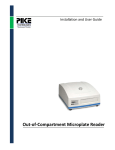
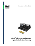
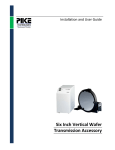
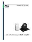
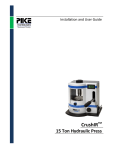
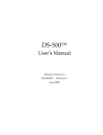
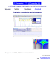
Installation and User Guide
FlexIRTM NIR Fiber Optic Accessory
The information in this publication is provided for reference only. All
information contained in this publication is believed to be correct and
complete. PIKE Technologies, Inc. shall not be liable for errors contained herein
nor for incidental or consequential damages in connection with the furnishing,
performance, or use of this material. All product specifications, as well as the
information contained in this publication, are subject to change without notice.
This publication may contain or reference information and products protected
by copyrights or patents and does not convey any license under the patent
rights of PIKE Technologies, Inc. nor the rights of others. PIKE Technologies, Inc.
does not assume any liability arising out of any infringements of patents or
other rights of third parties.
This document contains confidential or proprietary information of PIKE
Technologies, Inc. Neither this document nor the information herein is to be
reproduced, distributed, used or disclosed, either in whole or in part, except as
specifically authorized by PIKE Technologies, Inc.
PIKE Technologies, Inc. makes no warranty of any kind with regard to this
material including, but not limited to, the implied warranties of merchantability
and fitness for a particular purpose.
Copyright 1991-2014 by PIKE Technologies, Inc., Madison, WI 53719. Printed in
the United States of America. All world rights reserved. No part of this
publication may be stored in a retrieval system, transmitted, or reproduced in
any way, including but not limited to, photocopy, photograph, magnetic or
other record, without the prior written permission of PIKE Technologies, Inc.
Address Comments to:
PIKE Technologies, Inc.
6125 Cottonwood Drive
Madison, WI 53719
Phone
Fax
E-mail
Web Site
Jan. 1, 2014
(608) 274-2721
(608) 274-0103
[email protected]
www.piketech.com
Contents
Introduction
Unpacking Your Accessory
Packing List
Installation
Accessory Adjustment
Performance Verification
Solid Sampling
Liquid Sampling
Precautions
Options
1
2
2
3
4
5
6
7
7
7
Introduction
FlexIR™ Near-Infrared Fiber Optic accessory is a compact sample compartment-mounted accessory for
measuring the composition of a wide variety of solid and paste materials. Using near-infrared
chemometrics, qualitative product identification or quantitative analysis may be performed on
pharmaceutical, nutraceutical, chemical, polymer, textile, food, agricultural or other samples.
The FlexIR accessory features a high throughput, low-OH fiber optic probe with a reflectance tip and a
high-speed, low-noise Indium-Gallium-Arsenide detector with optics and electronics interface. The
FlexIR fits in the sample compartment of the FTIR spectrometer and connects to the detector port of the
spectrometer. The window is bonded and sealed to protect the probe tip from corrosive materials and
contamination.
PN 350-0451000-00
P a g e |1
Unpacking Your Accessory
In order for you to quickly verify receipt of your accessory, we have included a packing list. Please
inspect the package carefully.
Packing List
User Manual
PN 350-0451015
FlexIR Optical and Electronic
Interface Module
Quantity 1
PN 045-10XX
Fiber Optics and Cable
Quantity 1
Quantity 1
Probe Stand with Gold Reference
Quantity 1
PN 350-0451000-00
P a g e |2
Installation
Before installation, make sure the spectrometer is working in the near-infrared region without the
FlexIR. Please consult the manufacturer of the FT-IR spectrometer regarding the conversion of the bench
to near-infrared. This may involve replacing the beamsplitter and source to optimize for the 10,000 to
4000 cm-1 wavelength region of the IntegratIR. It is advisable to perform an alignment of the
interferometer before inserting the IntegratIR into the sample compartment.
Each FlexIR unit is manufactured to interface with a specific model FTIR spectrometer. Operation with a
different model may require a factory conversion to be performed by PIKE Technologies. Place the
Interface Module in the sample compartment of the spectrometer. The baseplate of the accessory
assures the alignment of the accessory relative to the beam coming from the spectrometer. Connect the
detector cable to the spectrometer.
CAUTION: Make sure power to the spectrometer bench is off before plugging in the
detector cable.
Use the included cable to connect to the external port of the spectrometer and turn the spectrometer
back on.
Attach the two SMA connectors of the Fiber Optic Probe to the Interface Module. The FlexIR is ready for
measurements.
SMA Connectors
Fiber Optic Probe
Optical and Electronic
Interface
Probe Stand
Figure 1. FlexIR NIR assembly
PN 350-0451000-00
P a g e |3
Accessory Adjustment
The accessory has been aligned and tested to ensure that it performs to specifications. No additional
alignment is necessary.
The gain of the FlexIR is set to allow the best signal-to-noise. Please check that the interferogram signal
magnitude does not exceed the A/D converter required signal magnitude. This is done by placing the
reflectance probe against the diffuse reference set into the bottom of the probe holder reference
position (Figure 3). The interferogram signal can be reduced by using the aperture selection on the
spectrometer. In the near-infrared high resolution is rarely used, thus the default aperture may be in the
fully open position or any of the smaller apertures that do not significantly reduce the light level.
Should a gain adjustment be necessary, which may be the case if switching between the diffuse probe
tip and the liquid tip, the housing of the accessory can be removed and the gain adjusted using the
potentiometer on the electronic board. This is typically a service function and PIKE Technologies should
be contacted before attempting to do this adjustment.
Fiber Optic
Connections
Detector Gain Adjust
(Service Only)
Figure 2. Interior view of FlexIR Electronic Interface Module
PN 350-0451000-00
P a g e |4
Performance Verification
With the accessory installed and the appropriate aperture set, insert the diffuse reflectance probe into
the reference side of the probe stand to contact the diffuse gold reference (Figure 3). Source intensities,
shape of the infrared beam, and the beam splitter characteristics vary from bench to bench. The single
beam spectra may appear slightly different than shown in Figure 4. Using a 1 minute data collect time,
collect a background followed immediately by a sample spectrum. The peak to peak noise around
6000 cm-1 should be equal to or less than 150 µAbs RMS.
Diffuse Gold
Reference Position
Figure 3. Probe stand with diffuse gold reference
Figure 4. Single beam energy of the FlexIR (Red), ratio of two consecutive 1 min spectra of gold reference
(Blue). Noise level around 6000 cm-1 should be less than 150 µAbs RMS.
PN 350-0451000-00
P a g e |5
Solid Sampling
Sampling with the FlexIR is as easy as placing the probe on the sample. The probe is designed to be used
with powders, plastics and other solid materials that have a flat part to contact the window on the probe.
For solid samples, reproducible sample positioning has to be assured. The window at the tip of the probe
is sealed using epoxy compound, thus it is relatively chemically inert and can be cleaned preferably with
alcohol or with acetone for samples which are more difficult to clean.
Samples for near-infrared need to be presented to the spectrometer in an optically uniform and
reproducible fashion to obtain the same spectrum every time. Parameters that have significant effect on
the samples are particle size and distribution, crystallinity, phase (for example, melted or solidified oils
have very different spectra), compression, temperature (especially water-containing samples) and other
physical or chemical differences.
In all cases, the accessory is measuring the reflected light, thus transparent materials such as films
produce very small signal. In certain cases, a reflective mirror can aid in returning the near-infrared light to
the collecting part of the fiber. This double transmission (called transflectance) is a convenient way of
measuring transparent or semi-transparent samples that have a reproducible thickness or pathlength.
Figure 5. Sampling with the FlexIR through a thin plastic bag is possible due to the weak near-infrared
signature of polyethylene.
PN 350-0451000-00
P a g e |6
To collect a spectrum background, position the probe in the diffuse gold reference slot on the probe
holder shown in Figure 3 prior to collecting the sample spectrum. Samples may be directly measured in
a container using the probe. The contact between the sample and the probe should be maintained
during the sample spectrum collection. Pressure on the sample should be maintained during the
measurement and applied reproducibly to achieve repeatable results. Glass or plastic containers can
also be used for samples, but the user must assure that the glass or plastic is uniform, reproducible and
as thin as possible to position the sample surface as close to the probe tip as possible. Solids, pastes and
powders can be measured.
The near-infrared region is not as sensitive to residual water vapor as the mid-infrared. If the resolution is
higher, the sharper water rotational-vibrational bands still are exhibited. Purging the sample compartment
will also reduce this effect for increased spectral reproducibility in the water vapor regions.
Liquid Sampling
The Liquid Probe Tip is transflection tip used with the FlexIR Near-Infrared Fiber Optic Probe for liquid
measurements. The tip is secured by threading it onto the probe end, after removal of the standard
diffuse tip. To install the liquids tip, unscrew the diffuse tip first and transferring the O-ring seal between
the probe body and the liquid tip. This O-ring seal is important
to assure that chemicals cannot migrate into the inside of the
probe. Prior to securing the liquids tip, make sure the O-ring is
not damaged and that the tip is threaded on properly.
Finger tightening is enough to assure proper seal. Tools are not
necessary, nor recommended, to tighten the tip.
Standard Tip
Liquid Gap
O-Ring Seal
Use of Liquid Probe
For measurements probe can be dipped in liquids. Please do not submerge too close to the handle,
because there is no chemically-resistant seal around the handle. For background, it is best to use pure
PN 350-0451000-00
P a g e |7
solvent. Otherwise, the dry cell can reflect the light differently from when the gap is filled with liquid.
The small gap can be cleaned between samples with a stream of solvent (alcohol, acetone, etc.) squirted
in the gap from the front and dried with a cloth or absorbent paper.
Please note that water has higher surface tension and may not fill the gap just by dipping the probe due
to the formation of an air bubble. To eliminate an air bubble from the gab, the probe can be held
slanted with the front lip upward and the probe can also be swished in the liquid.
Figure 1. Near-infrared transmission spectrum of biodiesel sample using the liquid tip.
PN 350-0451000-00
P a g e |8
Liquid Tip Specifications
Nominal Liquid Pathlengths
Window Material
Materials in Contact with Liquid
1.0 mm (two passes through 0.50 mm gap)
1.5 mm (two passes through 0.75 mm gap)
2.0 mm (two passes through 1.00 mm gap)
Borosilicate glass
Stainless steel, borosilicate glass, chemically resistant epoxy,
Viton O-ring (Call PIKE Technologies to inquire about
perfluoroelastomer O-ring)
Precautions
In order to provide the maximum signal in the infrared, with the minimum spectral interference, the
mirrors in this accessory are thin film coated. Since the coatings are soft, care must be taken to avoid
damage. Normally, these mirrors will not need cleaning since they are contained within the housing of
the accessory. If they do need cleaning, they may be gently swept with a camel hair brush. Under no
circumstances must the mirrors be rubbed with paper products such as “Kleenex” since this may scratch
the mirror coating.
Options
Part Number
045-2001
045-2000
045-2002
045-2010
PN 350-0451000-00
Description
Liquids Sampling Tip, 1.0 mm pathlength
Liquids Sampling Tip, 1.5 mm pathlength
Liquids Sampling Tip, 2.0 mm pathlength
Diffuse Reflection Tip for FlexIR NIR Probe
P a g e |9
6125 Cottonwood Drive · Madison, WI 53719-5120 · (608) 274-2721 (TEL) · (608) 274-0103 (FAX)
[email protected] · www.piketech.com