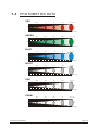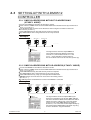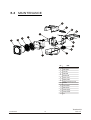
1
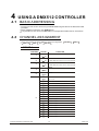
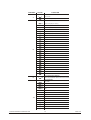
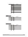
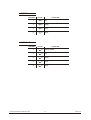
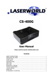
LED CUBE 49
User Manual
Please read this manual carefully before use!
T
ABLE OF CONTENTS
PART 1 PRODUCT (GENERAL)....................................................1.
1.1--PRODUCT INTRODUCTION.........................................................1.
1.2--PRODUCT FEATURES.................................................................1.
1.3--TECHNICAL SPECIFICATIONS.....................................................2.
1.4--PHOTOMETRIC DATA..................................................................3.
1.5--SAFETY WARNING......................................................................4.
PART 2 INSTALLATION...............................................................5.
2.1--MOUNTING...................................................................................5.
2.2--POWER CONNECTION..................................................................6.
2.3--ENTERTING UP WITH A DMX512 CONTROLLER.................................7.
2.3-1--DMX512 ADDRESSING WITHOUT ID ADDRESSING......................................7.
2.3-2--DMX512 ADDRESSING WITH ID ADDRESS..................................................7.
PART 3 DISPLAY PANEL OPERATION.........................................8.
3.1--BASIC..........................................................................................8.
3.2--MENU..........................................................................................9.
3.3-- STATIC COLOR..........................................................................10.
3.4-- AUTO .........................................................................................10.
3.5-- DMX ADDRESSING....................................................................10.
3.6-- RUN MENU.................................................................................11.
3.7--PERSONALITY.......................................................................... 11.
3.8-- ID ADDRESS.............................................................................. 11.
3.9-- ENTERTINGS .................................................................................11.
3.10-- PASSWORD .............................................................................12.
3.11--EDIT ........................................................................................ 12.
3.12-- FAN ENTERTING .......................................................................... 12.
PART 4 USING A DMX512 CONTROLLER....................................13.
4.1--BASIC ADDRESSING.................................................................13.
4.2--CHANNEL ASSIGNMENT............................................................13.
4.3--BASIC INSTRUCTIONS FOR DMX512 OPERATION (STAGE 1).....17.
PART 5 APPENDIX..................................................................... 18.
5.1--TROUBLE SHOOTING...............................................................18.
5.2--MAINTENANCE........................................................................ 19.
1
PRODUCT (GENERAL)
1.1
PRODUCT INTRODUCTION
This product is designed for indoor use. Suitable applications include wash or effect
lighting for stage or nightclub applications. This product can also be installed for use in
signage and advertising using the dynamic functions available with DMX512 control. Direct
input of DMX512 signal allows the units to be controlled from any DMX512 controller. This
product can be operated as a single unit or in multiple units for large applications.
1.2
PRODUCT FEATURES
LED FIXTURE
*
*
*
*
*
*
*
*
*
*
1 PRODUCT(GENERAL)
Dimmer 0-100%
Strobe
Automatic/Customs programs
LCD display
Display control 'lock-out'
Direct DMX512 input
Independant ID address
Stand-alone/ Slave
'Over-heat' protection
Fan speed control
1
2009.2.21
1.3
TECHNICAL SPECIFICATIONS
LED MODULE
LED MODULE:
Voltage
AC 100~240V...50/60Hz
Rated Power
60W
49pcs (14 x RED / 14 x GREEN /14 x BLUE/7 x WHITE)
LED/Unit
Output/LED
1W
Environment Temperature -20
Cooling
~40
Forced air convection
Dimensions
200 x 160 x265mm
Weight
2.5Kg
265mm
200mm
160mm
40mm
1 PRODUCT(GENERAL)
2
40mm
2009.2.21
PHOTOMETRIC DATA
RED
240
64
31
19.5
14.1 LUX
2
4
6
8
331
88.3
42.4
26.6
2
4
6
8
81
22.6
11.7
7.8
2
4
6
8
300
78.5
31.8
23.1
2
4
6
8
650
166
80
49.4
2
4
6
8
10Distance(m)
970
244
114.7
70
49.3 LUX
2
4
6
8
10Distance(m)
35
1.4
0
17.1 LUX
35
GREEN
10Distance(m)
0
6.2 LUX
35
BLUE
10Distance(m)
0
10Distance(m)
WHITE
35
17 LUX
0
35
0
RGBW
0
1 PRODUCT(GENERAL)
35 LUX
35
RGB
10Distance(m)
3
2009.2.21
1.5
SAFETY WARNING
IMPORTANT
ALWAYS READ THE USER MANUAL BEFORE OPERATION.
PLEASE CONFIRM THAT THE POWER SUPPLY STATED ON THE
PRODUCT IS THE SAME AS THE MAINS POWER SUPPLY IN YOUR
AREA.
This product must be installed by a qualified professional.
Always operate the equipment as described in the user manual.
A minimum distance of 0.5m must be maintained between the equipment and
combustible surface.
The product must always be placed in a well ventilated area.
Always make sure that the equipment is installed securely.
DO NOT stand close to the equipment and stare directly into the LED light
source.
Always disconnect the power supply before attempting and maintenance.
Always make sure that the supporting structure is solid and can support the
combined weight of the products.
The earth wire must always be connected to the ground.
Do not touch the power cables if your hands are wet.
ATTENTION
This product left the place of manufacture in perfect condition. In order to
maintain this condition and for safe operation, the user must always follow the
instructions and safety warnings described in this user manual.
Avoid shaking or strong impacts to any part of the equipment.
Make sure that all parts of the equipment are kept clean and free of dust.
Always make sure that the power connections are connected correct and
secure.
If there is any malfunction of the equipment, contact your distributor
immediately.
When transferring the product, it is advisable to use the original packaging in
which the product left the factory.
Shields, lenses or ultraviolet screens shall be changed if they have become
damaged to such an extent that their effectiveness is impaired.
The lamp (LED) shall be changed if it has become damaged or thermally
deformed.
1 PRODUCT(GENERAL)
4
2009.2.21
2
2.1
INSTALLATION
MOUNTING
HANGING
The LED fixture can be mounted in a hanging position
using the supporting bracket. The bracket should be
secured to the mounting truss or structure using a
standard mounting clamp. Please note that when
hanging the unit a safety cable should also be used.
UPRIGHT
The LED fixture can be mounted in an upright or
sitting position using the supporting brackets.
The LED MODULE can be mounted at any angle and in any
position. It is possible to further adjust the angle of the LED
MODULE using the two adjustment knobs located on the side of
the fixture.
2.2
POWER CONNECTIONS
@ 220V: 15 units may be connected in series
@120V: 7 units may be connected in series
Note:
1. If over 15 units to be connected, then a DMX signal amplifier is needed.
2. If the signal cable is over 60m between the DMX512 controller and fixture or beween two
fixtures, then a DMX signal amplifier is needed as well.
2 INSTALLATION
5
2009.2.21
2.3
SETTING UP WITH A DMX512
CONTROLLER
2.3-1 DMX512 ADDRESSING WITHOUT ID ADDRESSING
(STAGE 1 MODE)
Connect the DMX512 controller to the units in series.
Each unit has 10 DMX channels so the DMX Addresses should increase by increments of
10 (e.g. 1,11,22,33...)
The ID address has not been set so therefore when using the controller CH10 must
be inactive ( CH10=0 ).
Each DMX Address may be used as many times as required.
Any DMX address in the range from 001 to 512 may be used.
Example:
DMX Addr.1
DMX Addr.11
DMX Addr.22
............
DMX512
CONTROLLER
The figure above shows a simple DMX512
layout with the starting address of the first
unit set at 1, with the second set at 11 and
so on... (Note that when used in this way,
the CH10 ID function must be inactive (CH10=0))
2.3-2 DMX512 ADDRESSING WITH ID ADDRESS (STAGE 1 MODE)
Connect the DMX512 controller to the units in series
Each unit has 10 DMX channels so the DMX Addresses should increase by increments of
10 (e.g. 1,11,22,33...)
Each DMX Address may be used as many times as required.
Any DMX address in the range from 001 to 512 may be used.
Each DMX address may carry up to 66 separate ID addresses.
ID should be set in the menu on each unit in ascending values
(i.e. 1,2,3...)
ID addresses are accessible from CH10 on the DMX512 controller.
Example:
DMX Addr.1
ID Addr.1
DMX Addr.1
ID Addr.2
DMX Addr.1
ID Addr.3
DMX Addr.11
ID Addr.1
DMX Addr.11
ID Addr.2
DMX Addr.11
ID Addr.3
............
DMX512
CONTROLLER
2 INSTALLATION
The figure above shows a simple DMX layout
which has used three units at each DMX address.
The three units have different ID addresses which
allows the user to collectively control the whole
group of units at that DMX address by setting
CH10 to 0, or to control each unit independently by
first selecting the DMX address and then by using
CH10 to locate the target ID address.
6
2009.2.21
3
3.1
DISPLAY PANEL OPERATION
BASIC
MENU
MENU
ENTER
UP
DOWN
scroll through the main menu or exit from the current menu or function
ENTER Enter the currently selected menu or confirm the current function value
UP
DOWN
scroll 'UP' through the menu list or increase the value of the current function
scroll 'DOWN' through the menu list or decrease the value of the current function
3 DISPLAY PANEL OPERATION
7
2009.2.21
3.2
MENU
MENU
STATIC
RED
GREEN
BLUE
WHITE
STROB
(0~255)
(0~255)
(0~255)
(0~255)
(0~20)
AUTO
AUTO 1
AUTO 2
PLAY
AUTO 10
CUSTOM1
CUSTOM2
CUSTOM10
EDIT
CUSTOM1
CUSTOM2
SCEN1
SCEN2
CUSTOM10
SCEN100
ADDRESS
(001~512)
PERSON
STAGE1
ARC1
ARC1+D
(0~255)
(0~255)
(0~255)
(0~255)
(0~20)
(0~255)
(0~255)
RED
GREN
BLUE
WHIT
STROB
STEP
FADE
ARC2
ARC2+D
RUN MODE
DMX
SLAVE
ID
(01~66)
SETTINGS
FAN
OFF
LOW
NORMAL
HIGH
AUTO
UPLPAD
ID ON/OFF
RESET
PASSWORD
3 DISPLAY PANEL OPERATION
WAIT....
ON
OFF
Reset to factory?
WAIT....
ON
OFF
8
2009.2.21
3.3
STATIC COLOR
MENU
STATIC
(0~255)
(0~255)
(0~255)
(0~255)
(0~20)
RED
GREEN
BLUE
WHITE
STROB
STATIC
Select RED /
by pressing UP
Press ENTER
The fixture will be
3.4
GREEN / BLUE / WHITE / STROB and set the value
and DOWN
to save and back to the upper menu
automatic in Master running mode under this function
AUTO
MENU
AUTO
AUTO 1
AUTO 2
PLAY
AUTO 10
CUSTOM1
CUSTOM2
CUSTOM10
AUTO
Select the target AUTO program and press ENTER
Programs AUTO 01 to AUTO 10 are fully pre-programmed and will not be
altered
Programs CUSTOM 01 to CUSTOM 10 are fully pre-programmed and can be
edited in EDIT mode
The fixture will be automatic in Master running mode under this function
3.5
EDIT
MENU
EDIT
CUSTOM1
CUSTOM2
SCEN1
SCEN2
CUSTOM10
SCEN100
RED
GREN
BLUE
WHIT
STROB
STEP
FADE
(0~255)
(0~255)
(0~255)
(0~255)
(0~20)
(0~255)
(0~255)
EDIT
Enter EDIT to edit the custom programs C USTOM 1 to C USTOM 10
Each program has 30 steps to edit
Each step allows a creation of a scene using Red,Green,Blue,White,Strobe,
Step time,Fade time
3 DISPLAY PANEL OPERATION
9
2009.2.21
3.5
DMX ADDRESSING
MENU
(001~512)
ADDRESS
ADDRESS
Enter ADDRESS and set the DMX address
Press ENTER save the setting.
3.7
1~512
PERSONALITY
MENU
PERSON
STAGE1
ARC1
ARC1+D
ARC2
ARC2+D
PERSON
Enter PERSON and select
ARC2+D DMX mode
3.6
STAGE1 / ARC1
/ ARC1+D
/ ARC2
/
RUN MODE
MENU
RUN MODE
DMX
SLAVE
RUN MODE
Enter the RUN MODE mode to set working mode.
DMX mode is for using the DMX512 controller to control the fixtures.
SLAVE mode is for Master -- Slave operation, or controlled fixture by
Pix-controller.
Note: When fixtures are under Auto program operation, the
3.8
MENU
no works.
ID ADDRESS
MENU
(01~66)
ID
ID
Enter
3 DISPLAY PANEL OPERATION
ID
and set the ID address
10
1~66
2009.2.21
3.9
SETTINGS
MENU
SETTINGS
FAN
OFF
LOW
NORMAL
HIGH
AUTO
UPLPAD
ID ON/OFF
RESET
WAIT....
ON
OFF
Reset to factory?
WAIT....
FAN
Enter FAN and select the working mode of fan: OFF , LOW , NORMAL ,
HIGH or AUTO
UPLOAD
Select UPLOAD to upload the custom programs from the current MASTER unit to
the SLAVE units.
In order to activate the upload function the password must be entered
Password is the same as the main access password
When uploading the MASTER and SLAVE units will display YELLOW
If an error occurs when uploading the MASTER and/or SLAVE units will display RED
On successful uploading of the custom programs the MASTER and SLAVE units
will display GREEN.
ID ON/OFF
Choose
ON / OFF
to open or close ID
RESET
This function will reset all setting to the original factory setting
3.10
PASSWORD
MENU
PASSWORD
ON
OFF
PASSWORD
Enter the PASSWORD mode to set password ON/OFF
When password is activated, display will demand password each time
the fixture is powered on.
The factory default password is UP > DOWN > UP
> DOWN
3 DISPLAY PANEL OPERATION
11
2009.2.21
4
4.1
USING A DMX512 CONTROLLER
BASIC ADDRESSING
Connect all of the units in series using standard DMX512 signal cable or the IP65 rated cable
provided.
Set the DMX512 address in the DMX menu.
It is possible to have the same DMX address or independent addresses for each fixture.
4.2
CHANNEL ASSIGNMENT
Note: This product have five DMX512 channel configuration:
ARC 1+D , ARC 2 and
ARC 2+D
STAGE 1 , ARC 1
,
STAGE 1
CHANNEL
VALUE
FUNCTION
DIMMER
1
0
255
RED
2
0
255
(or STEP TIME when Customs 01-10 in CH8 is activated)
0
255
(or FADE TIME when Customs 01-10 in CH8 is activated)
GREEN
3
BLUE
4
0
255
WHITE
5
0
255
0
10
No function
11
35
RED 100% / GREEN UP / BLUE 0%
36
60
RED DOWN / GREEN 100% / BLUE 0%
61
85
RED 0% / GREEN 100% / BLUE UP
86
110
RED 0% / GREEN DOWN / BLUE 100%
111
135
RED UP / GREEN 0% / BLUE 100%
136
160
RED 100% / GREEN 0% / BLUE DOWN
161
185
RED 100% / GREEN UP / BLUE UP
186
210
RED DOWN / GREEN DOWN / BLUE 100%
211
215
WHITE 1: 3200K
216
220
WHITE 2: 3400K
MARCO
6
4 USING A DMX512 CONTROLLER
221
225
WHITE 3: 4200K
226
230
WHITE 4: 4900K
231
235
WHITE 5: 5600K
236
240
WHITE 6: 5900K
241
245
WHITE 7: 6500K
246
250
WHITE 8: 7200K
251
255
WHITE 9: 8500K
12
2009.2.21
CHANNEL
VALUE
FUNCTION
STROBE
7
0
4
No function
5
255
Strobe speed (0-20Hz)
Fans, Auto
8
0
10
Reset to display Fan setting
11
20
Fan closed (activated after 5 seconds)
21
30
Fan low speed (activated after 5 seconds)
31
40
Fan normal (activated after 5 seconds)
41
50
Fan high speed (activated after 5 seconds)
51
60
Fan auto speed (activated after 5 seconds)
61
70
Auto 1
71
80
Auto 2
81
90
Auto 3
91
100
Auto 4
101
110
Auto 5
111
120
Auto 6
121
130
Auto 7
131
140
Auto 8
141
150
Auto 9
151
160
Auto 10
161
170
Custom 1
171
180
Custom 2
181
190
Custom 3
191
200
Custom 4
201
210
Custom 5
211
220
Custom 6
221
230
Custom 7
231
240
Custom 8
241
250
Custom 9
251
255
Custom 10
AUTO SPEED ADJUSTMENT
9
When using CH8,AUTO01-AUTO10, this function activated
0
255
0
9
ID1~ID66
10
19
ID1
20
29
ID2
30
39
ID3
40
49
ID4
50
59
ID5
60
69
ID6
70
79
ID7
80
89
ID8
90
99
ID9
100
109
ID10
ID ADDRESS
10
4 USING A DMX512 CONTROLLER
110
119
ID11
120
129
ID12
130
139
ID13
13
2009.2.21
CHANNEL
VALUE
FUNCTION
140
149
ID14
150
159
ID15
160
169
ID16
170
179
ID17
180
189
ID18
190
199
ID19
209
ID20
200
10
210
ID21
211
ID22
254
ID65
255
ID66
ARC 1
CHANNEL
VALUE
FUNCTION
1
0
255
RED
2
0
255
GREEN
3
0
255
BLUE
ARC 1+D
CHANNEL
4 USING A DMX512 CONTROLLER
VALUE
FUNCTION
1
0
255
MASTER DIMMER
2
0
255
RED
3
0
255
GREEN
4
0
255
BLUE
14
2009.2.21
ARC 2
CHANNEL
VALUE
FUNCTION
1
0
255
RED
2
0
255
GREEN
3
0
255
BLUE
4
0
255
WHITE
ARC 2+D
CHANNEL
4 USING A DMX512 CONTROLLER
VALUE
FUNCTION
1
0
255
MASTER DIMMER
2
0
255
RED
3
0
255
GREEN
4
0
255
BLUE
5
0
255
WHITE
15
2009.2.21
4.3
BASIC INSTRUCTIONS FOR DMX512
OPERATION (STAGE 1)
MASTER DIMMER
CH1 controls the intensity of the currently projected color
When the slider is at the highest position (255) the intensity of the output is the maximum
RED, GREEN, BLUE & WHITE COLOR SELECTION
CH2, CH3, CH4 & CH5 control the intensity ratio of each of the RED, GREEN, BLUE & WHITE
LEDs.
When the slider is at the highest position (255) the intensity of the color is the maximum.
CH2, CH3, CH4 & CH5 can be combined together to create over 16 million colors.
COLOR MACROS
CH6 selects the required COLOR MACRO
CH6 has priority over CH2, CH3, CH4 and CH5
CH1 is used to control the intensity of the COLOR MACRO
STROBE
CH 7 controls the strobe of CH1 to CH5
ID ADDRESS SELECTION
Ch10 is used to select the target ID address.
Each independent DMX address may have upto 66 independent ID addresses.
An ID address of 0 will activate all ID address locations.
AUTO
CH8 selects the Fan Function, the preset AUTO programs Auto 01-10 or the custom programs
Custom 01-10
CH8 has priority over CH2, 3, 4, 5,6.
CH9 control speed of CH 8 (Auto 1 - Auto 10).
4 USING A DMX512 CONTROLLER
16
2009.2.21
5
APPENDIX
5.1
TROUBLE SHOOTING
SITUATION
No display
LCD MODULE on,
but no control
from display
LEDs of the same
color are not lit
LCD module on,
LEDs of all colors
are not lit
Display normal,
but no response
to DMX 512
controller
5 APPENDIX
CAUSE
ACTION
1) Power connection error
1) Check all power connections
2) Power switch damaged
2) Replace power switch
3) Display board damaged
3) Replace display board
1) Keyboard damaged
1) Replace keyboard
2) Display board damaged
2) Replace display board
1) LED PCB damaged
1) Check and Replace PCB board
2) LED PCB connection error
2) Check the wire connection
1) Driver PCB damaged
1) Replace driver PCB board
2) LED PCB damaged
2) Replace PCB board
3) LED PCB connection error
3) Check the wire connection
1) Signal connection error
1) Check and replace signal cable
2) DMX Address error
2) Check and reset DMX address
3) Master & slave mode error
3) Check and reset the working mode
4) ID error
4) Check and reset ID address
17
2009.2.21
5.2
MAINTENANCE
6
7
8
9
5
3
1
4
2
10
11
12
13
14
No
ITEM
1
Front cover
2
Clear plate
3
Lens set
4
LED PCB
5
Driver PCB
6
Plastic cover
7
Display PCB
8
Display supporting cover
9
Bracket
10
Fuse socket
11
DMX board
12
Power supply
13
Power socket
14
Fan
Version 1.0
5 APPENDIX
18
2009.2.21
EU-declaration of conformity
We hereby confirm that the following device
BRIGHTLIGHT LED CUBE 49
complies with the essential safety requirements, laid down in the regulations of the
committee to assimilate the provisions of law of all participating EU states on the
electromagnetic compatibility (89/336/EWG).
The device has been classified considering the following EU-norms on
electromagnetic compatibility:
DIN
DIN
DIN
DIN
EN
EN
EN
EN
55015: 2006
61547: 1995 + A1:2000
61000-3-2:2000 + A2: 2005
61000-3-3:1995 + A1: 2001
Assessment of compliance of the product with the requirements relating to the Low Voltage
Directive (LVD 2006/95/EG) was based on the following standards:
DIN EN 60065 : 2002
This declaration is executed on behalf of the BRIGHTLIGHT LED CUBE 49 manufacturer
Brightlight GmbH
Geschäftsfüher: Martin Werner
Rheinblick Residenz
Oberstrasse 1
8274 Tägerwilen
SCHWEIZ
place of business: 8274 Tägerwilen / SWITZERLAND
company number: CH-020.4.038.648-0
Commercial Registry Kanton Thurgau
www.brightlight-led.com
[email protected]
representative according to EMVG:
Cleantech Europe GmbH
Managing Director: Thomas Schulze
Fürkhofstr. 5
81927 München / DE