1
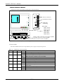
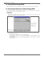
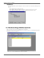
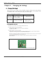
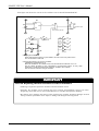
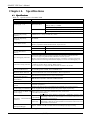
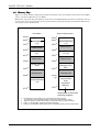
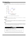
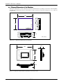
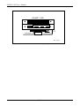
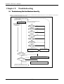
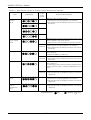
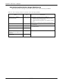
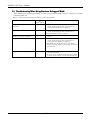
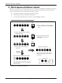
M16C/62P Compact Emulator
S3062PTS3062PT-CPE
Compact Emulator
with Real-time Trace
User’s Manual
Sunny Giken Inc.
S3062PT-CPE User’s Manual
Keep safety first in your circuit designs!
• Sunny Giken Inc. puts the maximum effort into making semiconductor products
better and more reliable, but there is always the possibility that trouble may occur with them. Trouble with
semiconductors may lead to personal injury, fire or property damage. Remember to give due consideration to safety
when making your circuit designs, with appropriate measures such as (i) placement of substitutive, auxiliary circuits,
(ii) use of non-flammable material or (iii) prevention against any malfunction or mishap.
Precautions to be taken when using this manual
• These materials are intended as a reference to assist our customers in the selection of the Sunny Giken Inc. product
best suited to the customer’s application; they do not convey any license under any intellectual property rights, or any
other rights, belonging to Sunny Giken Inc.
• Sunny Giken Inc. assumes no responsibility for any damage, or infringement of any third-party’s rights, originating in
the use of any product data, diagrams, charts, programs, algorithms, or circuit application examples contained in these
materials.
• All information contained in these materials, including product data, diagrams, charts, programs and algorithms
represents information on products at the time of publication of these materials, and is subject to change by Sunny
Giken Inc. without notice due to product improvements or other reasons. It is therefore recommended that
customers check the latest product information and pay attention to the information published by Sunny Giken Inc.
in various means, including Sunny Giken Homepage (http://www.sunnygiken.co.jp/english/) before purchasing a
product listed herein.
• Sunny Giken Inc. assumes no responsibility for any damage, liability or other loss resulting from the information
contained herein.
• When using any or all of the information contained in these materials, including product data, diagrams, charts,
programs, and algorithms, please be sure to evaluate all information as a total system before making a final decision
on the applicability of the information and products. Sunny Giken Inc. assumes no responsibility for any damage,
liability or other loss resulting from the information contained herein.
• All products of Sunny Giken Inc. are not designed or manufactured for use in a device or system that is used under
circumstances in which human life is potentially at stake. Please contact Sunny Giken Inc. when considering the use
of a product contained herein for any specific purposes, such as apparatus or systems for transportation, vehicular,
medical, aerospace, nuclear, or undersea repeater use.
• The prior written approval of Sunny Giken Inc. is necessary to reprint or reproduce in whole or in part these materials.
• If these products or technologies are subject to the Japanese export control restrictions, they must be exported under a
license from the Japanese government and cannot be imported into a country other than the approved destination.
Any diversion or re-export contrary to the export control laws and regulations of Japan and/or the country of
destination is prohibited.
• Please contact Sunny Giken Inc. for further details of these materials or the products contained therein.
Precautions
Precautions to be taken when using this product
• This product is a development support tool you can use in your program development and evaluation steps. When
development of your program is completed, always be sure to verify its operation by board-based evaluation and test
before putting it into mass production.
• Sunny Giken Inc. will not assume any responsibility for the results arising from the use of the product.
• Sunny Giken Inc. will respond to customer requests for the product, with expenses borne by Sunny Giken Inc. or the
customer, as follows:
(1) Repair or replacement of the product when it is found faulty
(2) Modification of nonconformity when the product contains nonconformity
• This product has been developed by assuming its use for program development and evaluation in laboratories.
Therefore, it does not fall under the application of electrical equipment control laws and protection against
electromagnetic interference when used in Japan.
Contact point for inquiries of the contents of the product and manual
For inquiries about the contents of the product or this manual, fill in the "Technical Support Application Form"
included in the manual and fax it to our dealer, Renesas Technology Corporation’s technical support desk. When
sending an email, write the same items of the "Technical Support Application Form" and send it to Renesas
Technology Corporation’s support desk ([email protected]).
[Maker] S
Sunny
unny Giken
Giken Inc.
[Dealer] Renesas Technology Corporation
[Technical Support]
Support] [email protected]
[User Registration]
Registration] [email protected]
[Homepage]
Homepage] http://www.sunnygiken.co.jp
http://www.sunnygiken.co.jp/english
sunnygiken.co.jp/english/
/english/
(1/51)
S3062PT-CPE User’s Manual
Preface
Thank you for purchasing the S3062PT-CPE. S3062PT-CPE is a compact emulator with the realtime trace function for M16C/62P of M16C/62 group.
This User’s Manual mainly describes specifications of the S3062PT-CPE, how to set up and
operate it. For details of the following products, which are used with the S3062PT-CPE, please
refer to online manuals attached to each product.
• Emulator debugger: PD30S
• C compiler: NC30WA Entry Version.
• Integrated development environment: TM
If you have any question or doubt about this product, please contact Sunny Giken Inc..
To use the product properly
Precautions for Safety
•In both this User’s Manual and on the product itself, several icons are used
to ensure proper handling of this product and also to prevent injuries to
you or other persons, or damages to your properties.
•The icons' graphic images and their meanings are given in "Chapter 1.
Precautions for Safety". Be sure to read this chapter and understand it
before using the product.
(2/51)
S3062PT-CPE User’s Manual
Terminology
Some specific words used in this User’s Manual are defined as follows:
• Emulator
Emulator
This means the S3062PT-CPE (this product).
• Emulator system
This means the emulator system built around the S3062PT-CPE emulator. The minimum
S3062PT-CPE emulator system is configured with an emulator, host machine and emulator
debugger.
• Host machine
machine
This means a personal computer used to control the emulator.
• Emulator debugger
This means a software tool, PD30S to control the emulator from the host machine through an
communications interface.
• Emulate MCU
This means the internal microcomputer mounted on the emulator which is operated in the
specific mode exclusively for tools.
• Target MCU
This means the microcomputer you are going to debug.
• Target system
This means an operation application system using the microcomputer to be debugged.
• ‘*’ after
after a signal name
The symbol "* " that is put after a signal name is used to show active LOW signal.
(e.g.
RESET* :Reset signal.)
• Vcc1, Vcc2 pins
For both Vcc1, and Vcc2 pins, Vcc indicates the power supply voltage of the target MCU.
(3/51)
Contents
Chapter 1. Precautions for Safety ................................................................................................7
1.1
Safety Symbols and Meanings ...................................................................................................................8
Chapter 2. Usage ..................................................................................................................15
2.1 Name of Each Part....................................................................................................................................16
(1) System Configuration...............................................................................................................................16
(2) Name of Each Part of Emulator ...............................................................................................................17
2.2 Starting Up the Emulator..........................................................................................................................19
2.3 Emulator Initial Setup ...............................................................................................................................20
(1) Selection Switches ...................................................................................................................................20
2.4 Connecting the Emulator System ..............................................................................................................21
(1) Connecting the PC Connecting Cable......................................................................................................21
(2) Connecting the DC Cable.........................................................................................................................21
2.5 Connecting the Target System (as occasion demands).............................................................................22
(1)Standard Connection .................................................................................................................................22
2.6 Turning On the Power ..............................................................................................................................23
(1) Checking the Connection of the Emulator System ..................................................................................23
(2) Turning On the Power..............................................................................................................................23
2.7 LED Display When the Emulator Starts Up Normally.............................................................................24
2.8 Starting Up Emulator Debugger PD30S...................................................................................................25
2.9 Setting the Operating Environment of Emulator Debugger PD30S .........................................................25
(1) INIT Screen..............................................................................................................................................25
(2) EMEM Screen..........................................................................................................................................26
2.10 When Emulator Debugger PD30S Starts Up Normally ..........................................................................26
Chapter 3. Changing the Settings ..............................................................................................27
3.1 Changing Clock Supply............................................................................................................................28
(1) Changing MCU main-clock .....................................................................................................................28
(2) Changing MCU sub-clock........................................................................................................................31
Chapter 4. Specifications ........................................................................................................33
4.1 Specifications............................................................................................................................................34
4.2 Memory Map.............................................................................................................................................35
4.3 DC Characteristics....................................................................................................................................36
(1) P1, P3-P5..................................................................................................................................................36
(2) P0, P2 .......................................................................................................................................................36
(3) P10 ...........................................................................................................................................................36
4.4 External Dimensions of the Emulator.......................................................................................................37
Chapter 5. Troubleshooting .....................................................................................................39
5.1 Troubleshooting Until the Emulator Starts Up.........................................................................................40
(1) Troubleshooting When the emulator Starts Up........................................................................................41
(2) Troubleshooting When Emulator Debugger PD30S Starts Up ................................................................43
5.2 Troubleshooting When Using Emulator Debugger PD30S.......................................................................44
5.3 When the Operation of the Emulator is Abnormal....................................................................................45
(1) Self-check Procedure in the Self-check Mode .........................................................................................45
(2) If an Error is Detected in Self-checks ......................................................................................................46
Chapter 6. Maintenance ..........................................................................................................49
6.1 Maintenance ..............................................................................................................................................50
(4/51)
(5/51)
S3062PT-CPE User’s Manual
MEMO
(6/51)
S3062PT-CPE User’s Manual
Chapter 1. Precautions for Safety
This chapter describes precautions for using this product safely and properly. For precautions for the
emulator debugger, please refer to User’s Manual included with your product.
1.1 Safety Symbols and Meanings
7
WARNING
Warning for Installation
8
Warning for Operating Environment
8
Caution to Be Taken for Modifying This Product
8
Cautions to Be Taken for This Product
8
Note on Malfunctions in the System
8
Notes on Differences between the Actual MCU and Emulator
9
Note on MCU Functions That Cannot Be Used with This Emulator
10
Note on Restrictions in Using the Emulator
11
Note on Controlling MCU Pins
13
Notes on the Target System (power supply, order of powering on)
13
CAUTION
IMPORTANT
(7/51)
S3062PT-CPE User’s Manual
Chapter 1.
Precautions for Safety
In both the User’s Manual and on the product itself, several icons are used to ensure proper handling
of this product and also to prevent injuries to you or other persons, or damages to your properties.
This chapter describes the precautions which should be taken in order to use this product safely and
properly. Be sure to read and understand this chapter before using this product.
1.1 Safety Symbols and Meanings
WARNING
If the requirements shown in the "WARNING"
sentences are ignored, the equipment may
cause serious personal injury or death.
CAUTION
If the requirements shown in the "CAUTION"
sentences are ignored, the equipment may
cause personal injury or damages to the products.
IMPORTANT
This shows other important notes for using this
product.
In addition to the three above, the following symbols are also used:
means WARNING or CAUTION
Example:
CAUTION AGAINST AN ELECTRIC
means PROHIBITION
Example:
DISASSEMBLY PROHIBITED
means A FORCIBLE
Example:
UNPLUG THE POWER CABLE FROM THE
RECEPTACLE.
The following pages describe the symbols "WARNING", "CAUTION", and "IMPORTANT".
(8/51)
S3062PT-CPE User’s Manual
WARNING
Warning for Installation:
•Do not set this product in water or areas of high humidity. Spilling water or some other liquid
into the main unit can cause an unrepairable damage.
Warning for Operating Environment:
•This equipment is to be used in an environment with a maximum ambient temperature of 35
degrees C. Care should be taken that this temperature is not exceeded.
CAUTION
Modifying This Product:
•Do not disassemble or modify this product. Disassembling and modifying the product will
void your warranty.
Cautions to Be Taken for Handling This Product:
•Use caution when handling the main unit. Be careful not to apply a mechanical shock.
•Do not touch the connector pins of the emulator main unit and the target MCU connector pins
directly. Static electricity may damage the internal circuits.
•Do not pull the compact emulator main unit with the PC cable for connecting to the target
system. The cable may be caused a break.
•Do not apply a voltage other than the specified voltage of the product, because it may cause
burns by abnormal heat generation and the failure of internal circuits.
IMPORTANT
Note on Malfunctions in the System
•If the emulator malfunctions due to the interference like external noise, please shut OFF power
to the emulator once and then reactivate it.
(9/51)
S3062PT-CPE User’s Manual
IMPORTANT
Notes on Differences between the Actual MCU and Emulator:
•Operations of the emulator differs from those of flash memory version MCUs as listed below.
(1) Reset condition
Set the time for starting up (0.2 to 0.8Vcc) 1[µs] or less.
(2) Data values of RAM and ROM areas at power-on
When power is turned on, the RAM and ROM areas of the emulator are defaulted to FFh.
(3) Register values when power is turned on
When power is turned on, the emulator's register values are defaulted to 0. However, the
program counter and ISP are defaulted to FFFFFh and 500h respectively.
(4) MCU Functions
On the emulator system, some of the MCU functions cannot be used. Please refer to the page 10 “Notes
on MCU Functions That Cannot Be Used with This Emulator” for details.
(5) Port Emulation
P0-P5, P10 are implemented by emulate circuit; their electrical characteristics are different.
P1, P3, P4, P5
The pull-up control register can be set, but actual signals will have 510KΩ
resistance automatically at input/output.
P0, P2
The pull-up control register can be set, but actual signals will have 510KΩ
resistance automatically at input/output. However, only when the analog input
is set, the pull-up circuit is disabled.
P10
Regardless of input/output, pull-up control register sets the 510KΩ resistance
automatically . However, only when the analog input is set, the pull-up circuit is
disabled. Note that once you set the analog input, pull-up circuit will remain
disabled unless analog port is switched to another port or RESET button of the
program is pressed on GUI.
* When using A/D converter, input is sent through the analog switch to A/D port.
* For ports other than P10, output voltage may be lower than actual chip depending on the connecting
circuits.
(6) Bus Timing Delay in Memory Expansion Mode
In the Memory Expansion Mode, occurrences of signals such as address, data, RD, and WR may delay
against the BCLK for the maximum of half of the BCLK time.
(7) BCLK
The BCLK output-forbidden bit is disabled during the memory expansion mode. Note that output is
done regularly.
(8) PLL Circuit
This product has a built-in external PLL circuit of the PLL synthesizer, and when using PLL, the internal
circuit will be operating.
•As items such as a package conversion unit are used between the emulate MCU and the target system, some
characteristics are slightly different from those of the actual MCU. Therefore, be sure to evaluate your system
with an evaluation MCU. Before starting mass mask production, evaluate your system and make final
confirmation with an ES (Engineering Sample) version MCU.
(10/51)
S3062PT-CPE User’s Manual
IMPORTANT
Notes on MCU Functions That Cannot Be Used with This Emulator:
•The following MCU features cannot be used with this emulator.
(1) Debugging cannot be done with this emulator in the “micro-processor mode”.
•When using this emulator, always set the processor mode bit in the processor mode register to the
"single-chip mode" or “memory expansion mode”.
•When using this emulator, fix the CNVSS pin at "L" level.
•Only a separate bus can be used in the “memory expansion mode”. A multiplex bus cannot be used.
(2) Oscillation circuits that use an oscillator cannot be used.
Because a package converter board is situated between the emulate MCU and the target system,
oscillation circuits in which an oscillator is connected between the XIN and XOUT pins will not
oscillate.
(3) Watchdog timers cannot be used.
MCU watchdog timers can only be used during program execution (free running). Disable watchdog
timers in all other program operations (break, dump, program forced stop, etc.).
Also, if the target system has a watchdog timer in its reset circuit, disable it, too, when using the
emulator.
(4) Single step interrupts cannot be used.
Single step interrupts cannot be used. The vector address of the single step interrupts is always
indicated in the emulator work area, and the vector address value cannot be changed.
(5) Software resets cannot be used.
Do not use software resets.
(6) Flash memory and EPROM modes are not emulated.
This emulator does not emulate the flash memory and EPROM modes. Also, the emulator does not
emulate the CPU rewrite mode in the flash memory mode.
(11/51)
S3062PT-CPE User’s Manual
IMPORTANT
Notes on Restrictions in Using the Emulator:
•The following restrictions apply to this emulator:
(1) Debug command execution when the BCLK is stopped:
When the BCLK is stopped, debug commands (break, dump, single-step, program forced stop, etc.)
cannot be executed. The BCLK can stop in the following cases:
•When the target clock is not oscillating;
•When the target MCU is on hold;
•When the target MCU is in the stop mode.
(2) MCU status during program hold:
With this emulator, putting the MCU on hold can stop the loop program at the specified address. Note
that, in this case, peripheral circuits are still operating.
(3) Interrupts during single step execution:
Interrupts are disabled during single step execution. Accordingly, interrupt processing is not
performed even if an interrupt request is sent.
(4) Address matched interrupt:
Do not set software breaks for an address for which an address matched interrupt is set. In step
execution, do not execute addresses that generate address matched interrupts.
(5) Stop and wait modes:
Do not use a single step for the command that shifts to the stop mode. Operation does not shift to the
wait mode when the command that shifts to the wait mode is executed as a single step.
(6) Stack area:
This emulator consumes 16 bytes of user stacks specified by ISP. If there is not enough user stack
area, it uses other areas not usable as stacks (SFR area, RAM area that stored data or ROM area),
which may damage the user program or destabilize emulator control. Therefore, ensure the maximum
+16 bytes of the area used by the user program for user stack area.
(7) Trace results for addresses that set software breaks:
Software breaks replace the original command with the BRK command that generates the
BRK interrupt. When trace results are viewed in the bus display, "0016" is displayed by
fetching (by command) the address that sets the software break, however in the reverse
assembly display, the "BRK" command is displayed.
(8) Protect register (PRC2):
When the protect register (PRC2) that enables writing in the port P9 direction register and the menu
key registers A3 is changed in the following way, the protect is not cancelled.
1) When the "command that sets PRC2 to '1' is executed (step execution)"
2) When the program is executed with a break point set between the "commands that set
PRC2 to '1'" and "when the register to be protected is set"
3) When "PRC2 is set to '1'" in the Dump or Script windows
(9) Debug command execution during user program execution:
The real-time aspect of the user program is not guaranteed when debug commands such as dump are
executed during user program execution.
(12/51)
S3062PT-CPE User’s Manual
IMPORTANT
(10) Debugging during XCIN execution
In the emulator system, internal memory (ROM; Flash memory, RAM) is used for the
emulation memory. Note that debugging may not be able to continue if debug command is executed
in a slow clock cycle in XCIN, such as 32.768kHz, due to the PD30S timeout.
(11) Response during user program execution
User programs and data to the emulation memory are updated just before user program execution.
Therefore, it may take several seconds before the user program execution if it needs to load a large
program or to rewrite software breakpoints.
(12) Hardware break
Break will occur after the execution, however, as operations such as the emulator’s conditional
judgment and MCU prefetch will accompany, it will be halted after processing a few instructions.
(13) Data Rom area from F000H to FFFFH
This ROM area can be rewritten only by downloading target programs. Rewriting by DUMP window,
and debugging by placement of execution codes are not possible.
(14) Debugging during DMA Operation
The debugger does not stop repeat transfer of the DMA during the operation of DMA repeat transfer,
even when the debugger is abeyant. However, it may cause an abnormal operation of the target
program when you re-execute the program.
Follow either one of the following instructions when you are to debug the target program which
operates the DMA repeat transfer:
- Before re-executing the target program, change the register directly to stop the DMA. Then
execute it.
- Set it to break with the DMA repeat transfer in abeyance.
(13/51)
S3062PT-CPE User’s Manual
IMPORTANT
Notes on Controlling MCU Pins:
•Some MCU pins controlled by the emulator.
(1) RESET* input
The RESET* input from the target system is accepted only the time during a user program is
being executed (only when the RUN Status LED of the emulator is lit.)
(2) NMI* input
The NMI* input from the target system is accepted only the time during a user program is
being executed (only when the RUN Status LED of the emulator is lit).
Notes on the Target System (power supply requirements, order of powering on):
•On this emulator, Vcc pins are connected in order to monitor the power voltage, and it cannot supply the
power to the target system. Therefore design your system so that the target system is powered separately.
•The voltage of the target system should be within the range of MCU specifications.
•Before powering on your emulator system, check that the host machine, the emulator, the converter board and
the target system are all connected correctly. Then, turn on the power to each equipment following the
procedure below.
(1)Turn ON/OFF the target system and the emulator as simultaneously as possible.
(2)When the emulator debugger starts up, check the target Status LEDs on the emulator to see if this
product is ready to operate.
Is the power supplied?
Is the clock supplied?
: Check that target Status LED (Power) is ON. *1
: Check that target Status LED (Clock) is ON. *2
*1 It is lit when the emulator is turned on.
*2 It is lit when the main clock is supplied to the emulator: it is not lit when the sub-clock is supplied from
the target (XCIN).
(14/51)
S3062PT-CPE User’s Manual
Chapter 2. Usage
This chapter describes how to operate this product.
2.1 Name of Each Part
15
2.2 Starting Up the Emulator
18
2.3 Emulator Initial Setup
19
2.4 Connecting the Emulator System
20
2.5 Connecting
Connecting Target system
21
2.6 Turning On the Power
22
2.7 LED Display When the Emulator Starts Up Normally
23
2.8
2.8 Starting Up Emulator Debugger PD30S
PD30S
24
2.9
2.9 Setting the Operating Environment of Emulator Debugger PD30S
PD30S
24
2.10
2.10 When Emulator Debugger PD30
PD30S Starts Up Normally
25
(15/51)
S3062PT-CPE User’s Manual
Chapter 2.
Usage
2.1 Name of Each Part
(1) System Configuration
Figure 2.1 shows the system configuration for this emulator.
c. AC adapter (Prepared by users)
e. Power supply for target system
(Prepared by users)
d. Target system
(Prepared by users)
a. Emulator
(S3062PT-CPE)
b. PC connecting cable
f. Host machine (Prepared by users)
Figure 2.1 System configuration
(a) Emulator S3062PT-CPE (included)
This is a compact emulator with the real-time trace function the M16C/62P in M16C/62
group. (Herein after referred as “emulator”.)
(b) PC connecting cable (included)
This is a USB interface cable for the host machine and the emulator.
(c) Power supply for emulator (Prepared by users)
This is a power supply for the emulator. Prepare the power supply separately. The DC cable
is included with this product.
(d) Target system (Prepared by users)
This is your application system. This emulator can be used without a target system.
(e) Power supply for the target system (Prepared by users)
This is a power supply for the target system. As this emulator cannot supply the power to the
target system, supply the power to the target system separately from the emulator.
(f) Host machine (Prepared by users)
This is a personal computer for controlling the emulator.
Prepare operation environment in which Windows98/Me/2000/XP OS can operate.
(16/51)
S3062PT-CPE User’s Manual
(2) Name of Each Part of Emulator
Figure 2.2 shows the name of each part of the emulator.
System Reset Switch
Sy stemReset
Sunny Gik en Inc.
S 306 2P T- CPE
DC IN
M16C/62P Compact Emulator
Power connector
Clock
USB
Power
Run
Reset
Halt
Error
LD5
USB cable
connecting
LD3
Status LED
LED1: Power
LED2: Clock
LED3: Reset
LED4: Run
LED5: Halt
LED6: Error
LD1
Oscillator Circuit Board Connector LD6 LD4 LD2
SW1 SW2 SW3
E-XIN / T-XIN / XIN SELECTION SWITCH (SW1)
XCIN/P87 SELECTION SWITCH (SW2)
XOUT SELECTION SWITCH (SW3)
Figure 2.2 Name of each part of emulator (upper side of S3062PT-CPE)
(a) Status LED
The Status LEDs indicate the target MCU's power supply and operating status.
Table 2.1 Definition of Status LED
Name
Power
Clock
Number Color
Status
Function
LD1
ON
Power is supplied to the target MCU.
OFF
Power is not supplied to the target MCU.
ON
Main clock is supplied to the target MCU.
OFF
Main clock is not supplied to the target MCU.
ON
Target MCU is resetting.
LD2
Green
Green
Reset
LD3
Red
Run
LD4
Green
Halt
Error
LD5
LD6
Red
Red
OFF
Target MCU setting is canceled.
ON
User program is being executed.
OFF
User program has been halted.
ON
OFF
Target MCU halts operation due to either command or conditions
of hardware.
Target MCU is operating.
ON
Emulator system has error.
OFF
Emulator system has no error.
(17/51)
S3062PT-CPE User’s Manual
(b) System reset switch
By pressing the system-reset switch, you can initialize the emulator system. Table 2.2 shows the
functions of the system reset switch depending on the state of emulator.
Table 2.2 Functions of system reset switch
Status of Emulator
Function
When the system reset switch is
pressed within 2 seconds of turning
on the power.
Changes into a special mode. (All indicators other than Power ON
and Clock of the Status LED flash.)
Then, when the emulator debugger, PD30S is started, changes into
a mode to force downloading a firmware.
When the system reset switch is
pressed during the special mode.
Executes self-check.
(All indicators other than Power ON and Clock of the Status LED
shift-flash.)
When the system
pressed while the
being halted.
When the system
pressed while the
being executed.
reset switch is
user program is
reset switch is
user program is
Initializes the emulator and waits for commands from the emulator
debugger.
Halts the user's program, initializes the emulator, and waits for
commands from the emulator debugger.
CAUTION
Notes on System Reset Switch:
•After pressing the system reset switch, reboot the emulator debugger PD30S; otherwise the display
of emulator debugger and the actual value (in the emulator) may not match.
•When the emulator debugger does not start up normally even after rebooting, turn off the emulator
and then turn on again.
(18/51)
S3062PT-CPE User’s Manual
2.2 Starting Up the Emulator
The procedure for starting up the emulator is shown in Figure 2.3. For more details, refer to each
section hereafter. And, when the emulator does not start up properly, refer to "Chapter 5.
Troubleshooting" (page 38).
E-XIN / T-XIN / XIN
XCIN / P87
XOUT
Select the selection
switch.
Set the switch according to each usage.
- E-XIN/T-XIN/XIN (SW1)
- XCIN/P87 (SW2)
- XOUT (SW3)
Connect the PC connecting cable.
Connect the PC connecting cable to the
connector of emulator and the USB port of
the host machine.
Connect the DC cable for emulator.
Connect the DC cable to the power
connector.
Connect the target system.
Connect the target system to the packageconverting unit at the bottom of emulator
(when necessary).
Recheck the connection, and turn on
the emulator.
When the target system is connected, turn on
the target system too. Turn them on
as simultaneously as possible.
Turn on the emulator.
Check "Power" and "Clock" of the Status
LEDs are lit. Even if the target system is not
connected, "Power" LED is lit.
Check the LED of emulator.
Start up the emulator debugger.
Start up the emulator debugger PD30S.
In the INIT dialog box of emulator debugger
PD30S, select a MCU file and press OK.
Specify the operating environment.
Emulator debugger PD30S offers
various debugging
functions. For details on PD30S, refer to
the online manual of PD30S.
Debug the program using PD30S.
Figure 2.3 Procedure for starting up the emulator
(19/51)
S3062PT-CPE User’s Manual
2.3 Emulator Initial Setup
Set the selection switches of the emulator according to purposes of use.
(1) Selection Switches
Switches
They are the switches to select the function of E-XIN/T-XIN/XIN, XCIN/P87, and XOUT pins. As shown
in Table 2.3 below, set the switch according to the usage of the pins.
Table 2.3 Setting the selection switch
Signal
Name
SW No.
Selection Switch Setting
E-XIN
E-XIN/
T-XIN/
XIN
SW1
SW2
T-XIN
SW3
XIN
T-XIN
P87
XOUT
Connecting XOUT pin to the target
system
E-XIN
XIN
T-XIN
Clock input from the target
circuit board. (oscillation
device only)
Using internal emulator sub-clock
(32.768kHz)
OPEN
XOUT
E-XIN
Clock input from oscillator
circuit board (option)
XCIN
XCIN/P87
XIN
XCIN
Internal clock input
(6MHz standard, factory
setting)
P87
Using P87 pin or target XCIN
(factory-setting)
OPEN
XOUT
Leaving XOUT pin OPEN
(factory-setting)
CAUTION
Notes on Setting Switches and Jumper Switches:
•Always shut OFF the power when changing the settings of the switches and
jumper switches, and connecting the cable.
•T-XIN, XCIN are used only when the target clock is output from oscillation device.
They cannot be used for oscillators such as quartz or ceramics.
(20/51)
S3062PT-CPE User’s Manual
2.4 Connecting the Emulator System
How to connect the emulator system is shown in Figure 2.4 below.
DC IN
S 30 62P T- CPE
To power supply for emulator
To host machine
SystemReset
Sunny Giken Inc.
M16C/62P Compact Emulator
Connect the DC cable to DC IN connector
Connect the PC connecting cable
to USB connector
Clock
USB
Power
Run
Reset
Halt
Error
Figure 2.4 Connecting the emulator system
(1) Connecting the PC Connecting Cable
Connect the PC connecting cable (included) to the USB connector and the USB port
of the host machine (see Figure 2.4).
(2) Connecting the DC Cable
Connect the DC cable for the emulator to the DC IN connector. The specifications of the
power supply for the emulator are listed in Table 2.4.
Table 2.4 Specification of power supply of emulator
Power supply voltage
DC9V/1.1 A
Figures 2.5 shows the specifications of the applicable plug, respectively.
1800mm
φ4.75mm
W ir e color
BL AC K a nd W HITE : D C+9 V( cen te r)
BL ACK : G ND (out side)
Figure 2.5 Specification of DC cable
φ1.7mm(Inside diameter)
Figure 2.6 Specification of applicable plug
CAUTION
Note on Connecting the Power Supply of Emulator:
•Be cautious about the polarity of the power supply. Connecting to the wrong electrode
could destroy internal circuits.
•Do not apply a voltage other than the specified voltage of the product (9V 1.1A), since
it may cause burn injuries and the failure of internal circuits.
•Be cautious when connecting the target system, as there is no power switch on the
emulator, and the emulator is turned on when DC9V is supplied from power unit.
(21/51)
S3062PT-CPE User’s Manual
2.5 Connecting the Target System (as occasion demands)
(1)Standard Connection
Connect the package S30830T-PTC1 conversion unit on the lower board of the emulator to a LCC
socket (option) on the target system. Make sure the position of No.1 pin before connecting.
The emulator can be used without a target system.
No.1 pin position
29
30
1
2
99
10 0
32 31
81 82
50 49
52
51
IC1
80
79
Figure 2.7 Package conversion unit on the lower board of the emulator
S3062PT-CPE
S30830T-PTC1
(100pin package converting unit)
LCC socket
100 pin
0.65mm pitch
LCC
(Manufactured by Yamaichi
Electronics: IC61-1004-051)
User’s target
Indicates the No.1 pin
position
Figure 2.8 Connecting 100-pin LCC socket
(22/51)
S3062PT-CPE User’s Manual
CAUTION
Notes on Connecting Target Systems:
•Be cautious not to attach the converter board in a wrong direction. It will cause a fatal
damage to the compact emulator.
•Always shut OFF power of the emulator and the target system when connecting and
disconnecting the target system.
2.6 Turning On the Power
(1) Chec
Checking
king the Connection of the Emulator System
Before turning the power ON, check the connection of the host machine and the emulator main
unit.
(2) Turning On the Power
Power ON the target system and the emulator main unit. Power ON/OFF the target system
and the emulator main unit should be done as simultaneously as possible.
CAUTION
Notes on Power Supply:
•As this emulator cannot supply power to the target system, provide the target system with a
separate power supply from that of the emulator.
•Do not change target system power supply voltage after power has been activated.
•The emulator is turned on by supplying DC9V from the power source unit, after connecting
power source unit and emulator with DC cable.
(23/51)
S3062PT-CPE User’s Manual
2.7
2.7 LED Display When the Emulator Starts Up Normally
After the emulator starts up, check the status of the LED to see if the emulator can be operated.
DC IN
Sy stemReset
S 30 62P T- CPE
Sunny Gik en Inc.
M16C/62P Compact Emulator
Status LED
Clock
Run
Reset
Halt
Error
USB
Power
LED1: Power
LED2: Clock
LED3: Reset
LED4: Run
LED5: Halt
LED6: Error
LD5 LD3 LD1
LD6 LD4
LD2
Figure 2.9 Positions of Status LED
Check to see if the POWER of the Status LED is lit immediately after the power is turned on. If it
is not lit, shut off the power for the emulator and check if the power supply for the emulator is
properly connected.
After the power is turned on, Status LEDs (LD1-6) will light for 12 seconds. Make sure that the
display of the Status LEDs becomes normal after that.
If the Status LEDs do not light as shown in Table 2.5, see "5.1 Troubleshooting
Until the Emulator Starts Up" (page 39).
Table 2.5 LED display when the emulator starts up normally
Error
Halt
Run
Reset
Clock
Power
:ON
:OFF
Note: This can be applied when operating with or without connection to a target system.
(24/51)
S3062PT-CPE User’s Manual
2.8
2.8 Starting Up Emulator Debugger PD30S
PD30S
After checking the emulator has started up normally, start up the emulator debugger PD30S.
2.9
2.9 Setting the Operating Environment of Emulator Debugger PD30S
After starting up PD30S, as the Init dialog box will open, set as shown in Figure 2.11. For details
of the Init dialog box, refer to User’s Manual of PD30S.
(1) INIT Screen
After starting up PD30S, Init dialog box will open. Set as per figure 2.10. Please refer to the
PD30S User’s manual for details of Init dailog box.
M3062P.mc
(1)Press “Refer” button
and select a MCU file.
(*1)
MCU file is saved in
the directory where
PD30S is installed.
(2)After completing
the setting, press OK.
Figure 2.10 Init dialog setting
(*1) MCU file to be selected
- Select M3062PC_A.MCU when using in single-chip mode.
- Select M3062PC_A.MCU when using A0000H-CFFFFH as internal ROM in memory
expansion mode.
- Select M3062PC_B.MCU when using A0000H-CFFFFH as external memory in memory
expansion mode.
(25/51)
S3062PT-CPE User’s Manual
(2) EMEM Screen
After pressing OK in the Init dialog box, select the mode to be used when following sceen
appears:
-
Select “Single Chip” for single chip mode.
Select “Memory Expansion 16Bit” for memoery expansion mode (data bus 16 bit).
Select “Memeory Expansion 8Bit” for memory expnsion mode (data bus 8 bit).
Figure 2.11 EMEM dialog setting
2.10
2.10 When Emulator Debugger PD30S Starts Up Normally
Figure 2.12 shows the screen when PD30S starts up normally.
If an error has been detected and PD30S has not started up, refer to "5.1 Troubleshooting Until
the Emulator Starts Up" (page 39).
Figure 2.12 Screen of PD30S when it starts up normally
(26/51)
S3062PT-CPE User’s Manual
Chapter 3. Changing the Settings
This chapter describes how to change the settings of this product.
3.1
3.1 Changing Clock Supply
27
(27/51)
S3062PT-CPE User’s Manual
Chapter 3.
Changing the Settings
3.1
3.1 Changing Clock Supply
There are three ways to supply a clock to the MCU, using the oscillator circuit of the emulator,
the oscillator circuit on the target system (only for oscillator output), or the oscillator circuit
board (option). Table 3.1 lists the factory-settings of each clock supply.
Table 3.1 Clock supply to the MCU
Clock
Description
Setting
XIN – XOUT
(Main clock)
Internal oscillator circuit
of emulator (6MHz)
SW1=XIN Side
XCIN – XCOUT
(Sub clock)
Internal oscillator circuit
of emulator (32.768kHz)
Selection switch
SW2= P87 Side
(Leave XCOUT open.)
(1) Changing MCU mainmain-clock
Following is the procedure how to change the MCU main clock:
<1> Using oscillation circuit of the emulator
In the emulator, 6MHz internal clock is built-in. (Standard)
(Set SW1 on XIN side.)
<2> Using oscillator circuit board (option)
If the emulator is going to be used in your desired oscillation frequency, please configure desired
oscillation circuit using oscillation circuit printed board (option).
The figure 3.1 shows the oscillator circuit board contour and pin locations. The circuit of the oscillator
circuit board (S30830T-OCS1) is shown in figure 3.2.
For mounting instructions, refer to page 29 “How to mount the oscillator circuit board
(S30830T-OSC1)”.
Example of a unit with oscillator
Figure 3.1 Outer shape of the oscillator circuit board (S30830T-OSC1)
(28/51)
S3062PT-CPE User’s Manual
The figure 3.2 shows the circuit of the oscillator circuit board (S30830T-OCS1).
3.3V
X1
1
4
C3
J1
SEL
VCC
JP1
OUT
2
0.1uF
1
INT
3
GND
3
4
EXT
Factory-Setting:INT Side
U1
2
1
2
1
2
3
3
74VHCU04
U1
U1
4
5
74VHCU04
9
8
11
10
13
12
VCC
GND
To Oscillation output
GND
6
R1
X2
C1
R2
C2
74HCU04
* Changing the oscillator
When changing the frequency by the oscillator, be sure to use 3.3V power source.
JP1 has to be set on INT side.
* Changing the frequency by using an oscillator
74VHCU04 is implemented on U1.
Mount an oscillator on X2, resistor on R1 & R2, and electrical condenser on C1, C2.
Set the values according to the manufacturer’s recommended values, as they differ
depending on resistors and electrical condenser oscillation drive capacity.
Set JP1 on EXT side when using an oscillator.
Figure 3.2 The circuit of Oscillation circuit board (S30830T-OSC1)
IMPORTANT
Notes on Replacing Internal Oscillator Circuit of Emulator:
•Soldering is required to replace the emulator's internal oscillation circuit.
•Generally, the oscillator can be replaced only twice (removal and installation count as one time).
Replacing it more than twice is not recommended since it will affect board pattern durability.
•Be cautious not to damage other devices when replacing the oscillator. Repairing damages incurred
during oscillator replacement can be subject to billing even during the warranty period.
(29/51)
S3062PT-CPE User’s Manual
Figure 3.3 shows the mounting position of the oscillation circuit board.
SystemReset USB
S3062P T-CP E
DC IN
M16C/62P Compact Emulator
Sunny Giken Inc.
Clock
Power
Run
Reset
Halt
Error
Oscillation circuit board mounting
Figure 3.3 Oscillation circuit board (S30830T-OSC1) mounting position
Mount it to the oscillation circuit board connector.
Oscillation
circuit board
Figure 3.4 How to mount Oscillation circuit board (S30830T-OSC1)
CAUTION
Notes on Mounting Oscillation Circuit Board:
•Always shut OFF power of the emulator when mounting the oscillation circuit board.
•Be careful about the direction you mount the oscillation circuit board. Physically, the
oscillation circuit board can be mounted in the reverse direction. In this case, power source
and grounding will be connected in the wrong direction thus it may cause breakage.
•The emulator case is conductive. Make sure that pins on solder side of the oscillation board
do not come in contact with the case.
(30/51)
S3062PT-CPE User’s Manual
<3> Using the oscillation circuit on the target system
When operating this product on the oscillation circuit of the target system, configure the
oscillation circuit as indicated in figure 3.5, and input the oscillation output of 50% duty
within the operating rage of the emulate MCU into XCIN.
Emulator
(Emulate MCU)
MCU)
XIN
XOUT
OPEN
Oscillation Output
Oscillation
Circuit
Figure 3.5 Target system Oscillation Circuit
As shown in the figure 3.6, in the oscillation circuit board where a resonator is connected between
XIN pin and XOUT pin, there are parts such as an emulation circuit board between emulate MCU and
the target system; it will not oscillate.
Emulator
(Emulate MCU)
MCU)
XIN
XOUT
Figure 3.6 Circuit that does not oscillate in the emulator
(2) Changing MCU subsub-clock
How to change the sub-clock supply is shown below.
(a)Using the oscillator circuit on the emulator
An oscillator for 32.768KHz is mounted inside the emulator.
(Set SW2 to XCIN.)
(31/51)
S3062PT-CPE User’s Manual
(b)Using the oscillator circuit on the target system
When operating the emulator by the oscillator circuit on the target system, construct the
circuit as shown in Figure 3.7 in the target system and input the oscillator output at 50%
duty (within the operating range of the emulate MCU) into the XCIN pin. (Set SW2 to
P87.) The XOUT pin should be open.
Emulator
(Emulate MCU)
XCIN
XCOUT
Open
Oscillation
Oscillation output
Oscillation
circuit
Figure 3.7 Oscillation Circuit on the target system
Note that in the oscillator circuit shown in Figure 3.8 where a resonator is connected
between the XIN and XOUT pins, oscillation does not occur because devices such as LCC socket
are used between emulate MCU and the target system.
Emulator
(Evaluation MCU)
XCIN
XCOUT
Figure 3.8 Circuit in which oscillation does not occur
IMPORTANT
Notes on Changing the Clock Supply:
• XCIN-XOUT (main clock) pins cannot be changed in the oscillator circuit on the emulator. When
changing the main clock, use an oscillation circuit board optionally sold. Note that oscillation
circuit on the target system can be used only for the oscillator output.
• For using XCIN-XCOUT (sub-clock) pins, it is necessary to change " SW2 (XCIN/P87 selection switch " of
the emulator. For how to set it, refer to "2.3 (1) P87/XCIN selection switch".(page 19).
(32/51)
S3062PT-CPE User’s Manual
Chapter 4.
Specifications
This chapter describes specifications of this product.
4.1 Specifications
33
4.2 Memory Map
34
4.3 DC Characteristics
35
4.4 External Dimensions of the Emulator
36
(33/51)
S3062PT-CPE User’s Manual
Chapter 4.
Specifications
4.1 Specifications
Table 4.1 Specifications of S3062PT-CPE
Function
Applicable MCUs
Clock supply (*1)
Specifications
Renesas Technology M16C family M16C/62 Group M16C/62P
Clock mounted on emulator (6MHz)
Main clock (XIN)
Multiply PLL by 4: 24MHz
Clock can be changed using oscillation circuit board (option).
Sub clock (XCIN)
Clock mounted on emulator (32.768kHz)
Frequency can be changed from the target system.
Maximum Operating
frequency
24MHz (Power voltage 5.0V/3.3V, 0 wait)
Minimum Operating
Frequency
32.768kHz
Usable MCU modes
Emulate MCU
Internal Emulation
Memory
Single-chip mode
Memory expansion mode (normal mode, separate bus)
M30627FHPGP
Emulate chip
M30624FGMFP
Control MCU
Internal RAM area
Using SRAM inside emulate chip: 31K bytes
Internal ROM area
Using flash memory inside flash memory: 384K bytes
Basic debugging functions
Download, S/W break (64 points), Program execution/stop (allows free-run
execution supporting S/W breaks), Hardware break (1-point)
Memory reference/Setting (reference/setting C-variables, run-time execution),
Register reference/setting, Disassemble display, C-source level debugging, etc.
Real-time tracing function
•1K-cycle bus information is recordable
(Address: 20 bits, Data: 16 bits, MCU status)
•2 trace modes are supported (Before Break mode/After Go mode)
Real-time RAM monitor
1K size (Mappable in SFR, Internal SRAM area)
Hardware Break Function
1 point (Command fetch, Data Read/Write, Data comparison)
Execution Time
Measurement Function
Host Operating
Environment
PC interface
Connection to Target
System
Time between program start to stop is measurable.
IBM PC/AT compatible / Windows 98/Me/2000/XP
USB 1.1 compatible (Full-speed mode)
Connect using package conversion unit (including 100P6S-A compatible as
standard equipment)
Package conversion units for100P6Q-A and 128P6Q-A are sold separately.
Power Supply for Emulator DC 9V supplied from external (prepare the power supply separately)
Power Voltage for MCU and VCC1=5.0V (±5%), 3.3V (±5%), VCC2=5V (±5%), 3.3V (±5%)
Power supply
It should be VCC1>VCC2.
Operating
Condition
Temperature 5-35 degrees centigrade / Humidity 20-80% (non
When
condensing) *Amount of dust should be around the same level as in
Operating
Environmental
general office environment.
Temperature -10-60 degrees centigrade / Humidity 0-90% (non
In Storage condensing) *Amount of dust should be around the same level as in
general office environment.
External
Dimensions/Weight
Approx. 105(W) x 34 (H) x 85 (D) mm (not including lugs) Approx 200g.
*1 Ring oscillators are not applicable.
(34/51)
S3062PT-CPE User’s Manual
4.2 Memory Map
Figure 4.1 shows memory maps when using the emulator. For the memory map of the actual MCU,
refer to the User’s Manual of your MCU.
Make note of the fact that the memory map of the actual MCU differ from that of emulator. Do not
access to the area noted "Do Not Access" in the memory map when using the emulator. Otherwise,
the emulator may malfunction.
Actual MPU
0000016
0040016
07FFF16
SFR area
Internal RAM area
(*4)
When using Emulator
0000016
SFR area
0040016
Internal RAM area
(*4)
07FFF16
External area
External area
0F00016
0F00016
Data ROM area
(*1) (*3)
Data ROM area
(*3)
0FFFF16
0FFFF16
External area
External area
2700016
2700016
Unusable area
(Debugger work
area)
Internal reserved
area
27FFF16
27FFF16
External area
External area
16
XXXXX
A0000
16
(*2)
Internal ROM
area
(Emulation
Memory)
Internal ROM area
(*4)
FFFFF16
FFFFF16
Not possible to write while
executing programs
*1. This ROM area can be rewritten only by downloading the target program.
(Not possible to rewrite in DUMP window, or debug by locating execution codes.)
*2. Beginning address of ROM area will depend on MCU file settings. (A0000H-FFFFFH)
*3 Setting 1 in the PM10BIT makes this area DATA ROM area.
*4 Setting 0 in the PM13BIT makes 4000H-7FFFH, and A0000H-CFFFFH become external area.
Figure 4.1 Memory map when using emulator
(35/51)
S3062PT-CPE User’s Manual
4.3
Characteristics
istics
4.3 DC Character
P0-P5, and P10 are actualized by emulate circuit, and have different electric characteristics from
the actual chip. Its output drive characteristics are shown in Figure 4.2. The input threshold is all
TLL level.
|IO|
Output
Vcc=5.0V
Room
Current
(mA)
Vo Output Voltage (V)
Figure 4.2 P0-P5 Output Drive Characteristics (Common)
(1) P1, P3P3-P5
Setting a pull-up control register is possible, but for actual signals, there is 510K-ohm
resistance for both input and output automatically.
(2) P0, P2
Setting a pull-up control register is possible, but for actual signals, there is 510K-ohm
resistance for both input and output automatically. However, only when the analog input is set,
the pull-up circuit is disabled.
(3) P10
Regardless of input/output, pull-up control register sets the 510K-ohm resistance automatically .
However, only when the analog input is set, the pull-up circuit is disabled. Note that once you
set the analog input, pull-up circuit will remain disabled unless analog port is switched to
another port or RESET button of the program is pressed on GUI.
CAUTION
Notes on Other Characteristics :
•The input threshold of above pins is all TTL level.
•When using A/D converter, Analog data will be input into A/D port via analog
switch.
•For ports other than P10, the output voltage may become less than the actual
(36/51)
S3062PT-CPE User’s Manual
4.4
4.4 External Dimensions of the Emulator
External dimensions of the emulator, External dimensions of package conversion unit(100P6S),
and External dimensions when connecting to target system are shown in Figure 4.3, 4.4, and 4.5
respectively.
105
DC IN
SystemReset
85
Clock
USB
Power
Run
Reset
Halt
Error
34.5
Unit: [mm]
*Lugs are not included
Figure 4.3 External dimensions of emulator
13.5
55.0
80
51
81
50
CN2
CN1
40.0
31
100
1
IC1
30
13.5
Figure 4.4 External dimensions of package conversion unit
(37/51)
S3062PT-CPE User’s Manual
S3062PT- CPE
9.5
L CC socket
17.0
Unit :[mm]
Figure 4.5 External dimensions when connecting to target system
(38/51)
S3062PT-CPE User’s Manual
Chapter 5. Troubleshooting
This chapter describes how to troubleshoot when this product does not work properly.
5.1 Troubleshooting Until the Emulator Starts Up
39
5.2 Troubleshooting When Using Emulator Debugger PD30S
42
5.3 When the Operation
Operation of the Emulator is Abnormal
43
(39/51)
S3062PT-CPE User’s Manual
Chapter 5.
Troubleshooting
5.1 Troubleshooting Until the Emulator Starts Up
Figure 5.1 shows the flowchart to remedy the troubles from the time when power to the emulator is activated
until the emulator debugger starts up.
Trouble shooting before starting
up the Emulator
【Self-check Sequence When the Emulator Starts Up】
Self-checks start automatically after
turning on the emulator
Turning on the Emulator
Self-check executes for
approximately 8
seconds after turning on
the emulator
Result of checking
emulator function
Error
Normal
Is the power
supplied to the
target?
No
Yes
No
NMI*pin=H?
Yes
No
CNVss*pin=L?
Yes
No
Is RESET* control on
emulator possible?
Yes
No
Is ICLK being
output?
Yes
Checks initialization of
emulator memory
Error
Normal
Self-check terminated normally.
Status LED displays normally.
Self-check error detected.
Status LED displays
abnormally.
Error detected in self-check
Result of checking
emulator function
Self-check
terminated normally
Refer to “Troubleshooting When the Emulator Starts Up”
Error detected
Starting up PD30S
Started up normally. Program
Window Displayed
Refer to “Troubleshooting When PD30S Starts Up”
Emulator system started up normally
Figure 5.1 Flowchart to remedy the troubles
(40/51)
S3062PT-CPE User’s Manual
(1) Troubleshooting When the emulator Starts Up
Table 5.1 lists how to remedy the troubles when the Status LED of the emulator display is
abnormal after powering on the emulator.
When the error is detected, shut off the power of the emulator and the target system and follow
the steps in Table 5.1. Then, reactivate the power of the emulator and the target system.
(41/51)
S3062PT-CPE User’s Manual
Table 5.1 Error display and how to remedy it when starting up the emulator
Item
Emulator
function
check
Power supply for
target system
check
NMI* pin check
CNVss pin check
Reset control
check
Emulation
memory
initialization
error
Connection
to the
target
system
LED display
Error
Halt
Run
Reset Clock
Power
−
Error
Halt
Run
Reset Clock
Power
−
Error
Halt
Run
Reset Clock
Power
−
Error
Halt
Run
Reset Clock
Power
−
Error
Error
Error
Halt
Halt
Halt
Run
Run
Run
Reset Clock
Reset Clock
Reset Clock
Power
Power
Power
Symptoms & Checkpoints
Emulator does not work properly.
⇒Check power is being supplied to the emulator.
⇒The emulator may be damaged. Contact your nearest
distributor.
Connected
Emulator does not work properly because power is not
being supplied to the target system.
⇒Check power is being supplied to the target system.
Not
connected
Emulator does not work properly.
⇒Check power is being supplied to the emulator.
⇒The emulator may be damaged. Contact your nearest
distributor.
Connected
Emulator does not work properly because the NMI*
pin is "L" level.
⇒Check the NMI pin is "H" level.
Not
connected
Emulator does not work properly.
⇒The emulator may be damaged. Contact your nearest
distributor.
Connected
Emulator does not work properly because the CNVSS
pin is "H" level.
⇒ Debugging cannot be done with this emulator in the
“micro-processor mode”. Check the CNVSS pin is "L"
level.
Not
connected
Emulator does not work properly.
⇒The emulator may be damaged. Contact your nearest
distributor.
Error
Halt
Run
Reset Clock
Power
−
Emulator does not work properly.
⇒Check power is being supplied to the emulator.
⇒The emulator may be damaged. Contact your nearest
distributor.
Error
Halt
Run
Reset Clock
Power
−
Emulator does not work properly.
⇒The emulator may be damaged. Contact your nearest
distributor.
Explanatory note)
(42/51)
:ON
:Blinking
:OFF
S3062PT-CPE User’s Manual
(2) Troubleshooting When Emulator Debugger PD30S Starts Up
Table 5.2 lists error messages and how to remedy them when starting up PD30S.
Table 5.2 Error message and how to remedy it when starting up PD30S
Error
Communication ERROR.
Can't accept data.
Connection to
the
target system
−
Not Compact Emulator.
−
Target MCU is not given clock.
−
Target MCU is unable to reset.
−
The version of PD30S and the
firmware on the target are not
compatible.
Please download the firmware
to the target.
−
Checkpoint
⇒Check the emulator's Status LEDs. If
flashing, the emulator is not working properly.
Check settings as explained in
"(1)Troubleshooting When the Emulator Starts
Up".
⇒Check the connection of the PC connecting cable.
⇒Check if any equipment other than emulator is
connected.
⇒Check if the emulator system's oscillation circuit
works properly.
⇒Contact your nearest distributor.
−
(43/51)
S3062PT-CPE User’s Manual
5.2 Troubleshooting When Using Emulator Debugger PD30S
After PD30S has started up normally, in case errors occurred while using it, remedy the troubles
referring Table 5.3.
Table 5.3 Error message and how to remedy it when using PD30S
Error
Target MCU is not given clock
currently.
Connection to
the
target system
−
Checkpoint
⇒Check if the emulator system's oscillation
circuit works properly. Also, please refer to
“2.3(1) Selection Switch” on page 19.
−
⇒Check if the emulator system's oscillation
circuit works properly. Also, please refer to
“2.3(1) Selection Switch” on page 19.
Target MCU is reset state.
Please reset target systems.
Target MCU is HOLD state.
Connected
⇒The target MCU has been reset. Cancel the
reset.
⇒Check if the emulator system's oscillation
circuit works properly. Also, please refer to
“2.3(1) Selection Switch” on page 19.
⇒The MCU may be in the stop or wait mode.
Either reset the MCU or cancel the mode with
an interrupt.
Target MCU is not given power.
Connected
Target MCU is unable to reset.
−
⇒Check the power supply and GND are
connected properly.
⇒If there is no problem found with the target
system, please contact your nearest distributor.
(44/51)
S3062PT-CPE User’s Manual
5.3 When the Operation of the Emulator is Abnormal
Self-check is a function to check the memory etc. mounted in the emulator. Self-check is executed
when the emulator starts up, and detailed check is executed by following the procedure below.
For this self-check, be sure to disconnect the target system.
(a)
Set the dip switch of the emulator as factory setting.
(b)
If the target system is connected, disconnect it.
(c)
Use a main clock mounted as the factory setting (6MHz oscillator)
(1) SelfSelf-check Procedure in the SelfSelf-check Mode
Error
LD6
Halt
LD5
Run
LD4
Reset
Clock
Power
LD3
LD2
LD1
System
Reset
(1) Within 2 seconds of activating power
to the emulator, press the RESET
switch.
(2) Status LEDs repeat blinking
simultaneously.
Error
Halt
LD6
LD5
Error
Halt
LD6
LD5
Run
Reset
Clock
Power
LD4
LD3
LD2
LD1
Run
Reset
Clock
Power
LD4
LD3
LD2
LD1
System
Reset
(3) Press the system reset switch
again after checking Status
LEDs blink.
System
Reset
(4) Status LEDs repeat blinking in
[When error detected]
succession.
Approx.
4 minutes
Error
Halt
LD6
LD5
Run
LD4
Reset
Clock
Power
LD3
LD2
LD1
One or more Status LEDs repeat
blinking depending on the content
of the error
[When self-checks terminated normally]
Error
Halt
LD6
LD5
Run
Reset
Clock
Power
LD3
LD2
LD1
LED display
LD4
For starting up the emulator after selfcheck, shut off the power of the emulator
and reactivate it.
Figure 5.2 Self-check procedure
(45/51)
ON
Blinking
OFF
S3062PT-CPE User’s Manual
(2) If an Error is Detected in SelfSelf-checks
checks
Table 5.4 lists how to remedy the troubles if the Status LED display is abnormal in selfchecks.
When an error is detected, shut off the power of the emulator and the target system and
follow the steps in the Table 5.4. Then, reactivate the power of the emulator and the target
system.
CAUTION
Notes on Self-checks:
•Be sure to disconnect the target system before executing self-checks.
•If self-checks do not result normally, the emulator may be damaged. Please
contact your nearest distributor.
•When an oscillator installed in the emulator is changed, self-checks may not
terminate normally. Use the oscillator of 6MHz when executing self-checks.
(46/51)
S3062PT-CPE User’s Manual
Table 5.4 Error display in self-checks and how to remedy it.
Checkpoint
LED display
Error
Halt
Run
Reset
Clock Power
Error
Halt
Run
Reset
Clock Power
Emulator does not work properly.
⇒Check if power is being supplied to the emulator.
⇒If power is being supplied to the emulator, the emulator
may be damaged.
Report the LED status to your nearest distributor.
Error
Halt
Run
Reset Clock Power
Error
Halt
Run
Reset Clock Power
Error
Halt
Run
Reset
Clock Power
Error
Halt
Run
Reset Clock Power
Error
Halt
Run
Reset Clock Power
Error
Halt
Run
Reset Clock Power
Error
Halt
Run
Reset Clock Power
Error
Halt
Run
Reset Clock Power
Error
Halt
Run
Reset Clock Power
Error
Halt
Run
Reset Clock Power
Error
Halt
Run
Reset Clock Power
Error
Halt
Run
Reset Clock Power
Explanatory note)
(47/51)
:ON,
:Blinking,
:OFF
S3062PT-CPE User’s Manual
MEMO
(48/51)
S3062PT-CPE User’s Manual
Chapter 6. Maintenance
This chapter describes how to maintenance, repair provisions and how to request for repair.
6.1 Maintenance
49
(49/51)
S3062PT-CPE User’s Manual
Chapter 6.
Maintenance and Guarantee
6.1 Maintenance
If dust or dirt collects on any equipment of your emulation system, wipe it off with a soft dry cloth.
Do not use thinner or other solvents because these chemicals can cause the equipment's surface
coating to separate.
CAUTION
Note on Shipping the Product:
•When sending your S3062PT-CPE for repair, use the packing box and cushion material
supplied with the S3062PT-CPE when delivered to you and specify handling caution
for it to be handled as precision equipment.
If packing of your product is not complete, it may be damaged during transportation.
When you pack your product in a bag, make sure to use conductive polyvinyl supplied
with the S3062PT-CPE (usually a blue bag). When you use other bags, they may cause
a trouble on your product because of static electricity.
(50/51)
Technical Support Communication Sheet
Date :
/
( Total Pages :
/
)
To
Contact Address
Product Information
Emulator : S3062PT-CPE
Serial number :
Company :
Emulator debugger : PD30S
Version :
Host machine :
OS & version :
Target MCU :
Department :
Responsible person :
Phone :
FAX :
E-mail :
Address :
Message :
Please fill in within heavy-line frame.
Date received :
/
/
/
Date replied :
Person in charge :
MEMO :
Consecutive No.
(51/51)
Inquiries (Attach a list of your inquiries, if necessary.)
(52/51)
Overseas Specifications
• Obtaining the CE Mark: (EMI: EN55011 Group1 Class A, EMS: EN61000-6-2)
• FCC Compliance:
This device complies with part 15 of the FCC Rules. Operation is subject to the following two
conditions;
(1) This device may not cause harmful interference, and (2) this device must accept any interference received,
including interference that may cause undesired operation.
S3062PT-CPE User’s Manual
Date of Issue
Revision Date
Editor
Published by
:
:
:
:
E-mail
:
April, 2003(First Edition)
Oct, 2003 (Third Edition)
Sunny Giken Inc.
Sunny Giken Inc.
3-1-9 Nishidai, Itami, Hyogo
JAPAN 664-0858
[email protected]


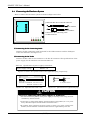
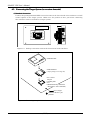
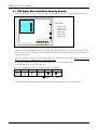

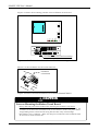
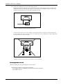
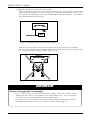


![[S3062PT-CPE-2] User`s Manual(First Edition): CPE62PSUE_2](http://vs1.manualzilla.com/store/data/005668190_1-0d028d6af383e5d06430420ca44dee4c-150x150.png)
![[S30830T-CPE] Users Manual: CPE83SUE](http://vs1.manualzilla.com/store/data/005890174_1-2a1526c3cbd1c0db150881a0418c3ddc-150x150.png)