1
Functional Description
2.3.14
CP6012
XMC Interface
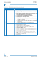
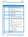
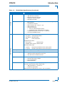
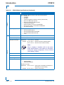
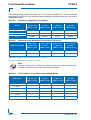
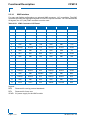
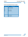
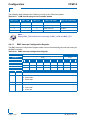
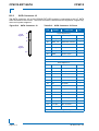
For easy and flexible configuration one onboard XMC connector, J15, is available. The XMC
connector provides the high-speed signals for a x8 PCI Express interface. For user-defined rear
I/O signals, the J27 (Jn4) PMC connector must be used.
PRELIMINARY
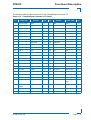
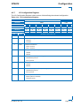
Table 2-22: XMC Connector J15 Pinout
PIN
ROW A
ROW B
ROW C
ROW D
ROW E
ROW F
1
PET0p0
PET0n0
3.3V
PET0p1
PET0n1
VPWR
2
GND
GND
TRST#
GND
GND
MRSTI#
3
PET0p2
PET0n2
3.3V
PET0p3
PET0n3
VPWR
4
GND
GND
TCK
GND
GND
MRSTO#
5
PET0p4
PET0n4
3.3V
PET0p5
PET0n5
VPWR
6
GND
GND
TMS
GND
GND
+12V
7
PET0p6
PET0n6
3.3V
PET0p7
PET0n7
VPWR
8
GND
GND
TDI
GND
GND
-12V
9
RFU
RFU
RPS
RFU
RFU
VPWR
10
GND
GND
TDO
GND
GND
GA0
11
PER0p0
PER0n0
MBIST#
PER0p1
PER0n1
VPWR
12
GND
GND
GA1
GND
GND
MPRESENT#
13
PER0p2
PER0n2
3.3V AUX
PER0p3
PER0n3
VPWR
14
GND
GND
GA2
GND
GND
MSDA
15
PER0p4
PER0n4
RPS
PER0p5
PER0n5
VPWR
16
GND
GND
MVMRO
GND
GND
MSCL
17
PER0p6
PER0n6
RFU
PER0p7
PER0n7
RFU
18
GND
GND
RPS
GND
GND
RPS
19
CLK+0
CLK-0
RPS
WAKE#
ROOT0#
RPS
Legend:
RPS
RFU
VPWR
Reserved for use by protocol standards
Reserved for future use
5V power supply for the XMC module
Page 2 - 24
ID 33274, Rev. 3.0