1
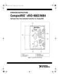
ActualOutput = Vext – (Iflow × 0.3 Ω)
where
ActualOutput is the voltage sourced by VOUT
Vext is the voltage provided by the external power supply
Iflow is the current flow through the VOUT terminal
Note Using a 5–10 V external supply increases the
output impedance to a maximum of 2 Ω. This increase
limits the amount of current each channel can supply.
Refer to the Specifications section for more information.
Table 3 shows some common combinations of output current levels
on several channels. Combinations are valid from –40 to 40 °C for
the cFP-DO-401 and from –40 to 70 °C for the FP-DO-401.
Table 3. Common Output Configurations
Channel Subset
Channel Subset
Total A2
14 channels @ 0.75 A
—
7.88 A2
8 channels @ 1 A
—
8 A2
5 channels @ 1.25 A
—
7.81 A2
8 channels @ 0.75 A
8 channels @ 0.5 A
6.5 A2
4 channels @ 1.25 A
3 channels @ 0.75 A
7.94 A2
3 channels @ 1.5 A
1 channel @ 1 A
7.75 A2
Protection for Inductive Loads
When an inductive load, such as a motor or relay, is connected
to an output, a large counter-electromotive force may occur at
switching time because of the energy stored in the inductive load.
This flyback voltage can damage the output and the power supply.
It is best to limit flyback voltages by installing a flyback diode
across an inductive load. Typically, you should mount the flyback
diode within 18 in. of the load. Figure 4 shows one channel
connected to an inductive load with a flyback diode.
© National Instruments Corp.
7
FP-DO-401 and cFP-DO-401