1
1.1 The Nature of Software...
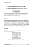
Object-Oriented Software Engineering
Practical Software Development using UML and Java
Chapter 1:
Software and Software Engineering
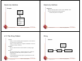
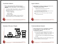
Software is intangible
Hard to understand development effort
Software is easy to reproduce
Cost is in its development
—in other engineering products, manufacturing is the
costly stage
The industry is labor-intensive
Hard to automate
© Lethbridge/Laganière 2001
The Nature of Software ...
Chapter 1: Software and Software Engineering
2
The Nature of Software
Untrained people can hack something together
Quality problems are hard to notice
Software is easy to modify
People make changes without fully understanding it
Software does not ‘wear out’
It deteriorates by having its design changed:
—erroneously, or
—in ways that were not anticipated, thus making it
complex
© Lethbridge/Laganière 2001
Chapter 1: Software and Software Engineering
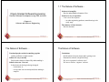
Conclusions
Much software has poor design and is getting worse
Demand for software is high and rising
We are in a perpetual ‘software crisis’
We have to learn to ‘engineer’ software
3
© Lethbridge/Laganière 2001
Chapter 1: Software and Software Engineering
4
Types of Software...
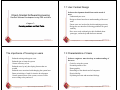
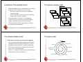
Types of Software
Custom
For a specific customer
Generic
Sold on open market
Often called
—COTS (Commercial Off The Shelf)
—Shrink-wrapped
Embedded
Built into hardware
Hard to change
© Lethbridge/Laganière 2001
Chapter 1: Software and Software Engineering
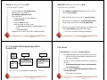
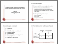
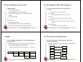
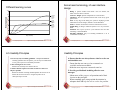
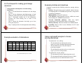
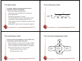
Differences among custom, generic and embedded
software
5
Types of Software
Generic
medium
Embedded
high
Total
processing
power
devoted to running this type
of software
low
high
medium
Worldwide annual
development effort
high
medium
low
© Lethbridge/Laganière 2001
Chapter 1: Software and Software Engineering
6
1.2 What is Software Engineering?...
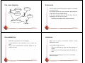
The process of solving customers’ problems by the
systematic development and evolution of large, highquality software systems within cost, time and other
constraints
Real time software
E.g. control and monitoring systems
Must react immediately
Safety often a concern
Data processing software
Used to run businesses
Accuracy and security of data are key
Solving customers’ problems
This is the goal of software engineering
Sometimes the solution is to buy, not build
Adding unnecessary features does not help solve the
problem
Software engineers must communicate effectively to
identify and understand the problem
Some software has both aspects
© Lethbridge/Laganière 2001
Custom
low
Number of copies in use
Chapter 1: Software and Software Engineering
7
© Lethbridge/Laganière 2001
Chapter 1: Software and Software Engineering
8
What is Software Engineering?…
What is Software Engineering?
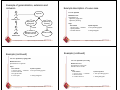
Systematic development and evolution
An engineering process involves applying well understood
techniques in a organized and disciplined way
Many well-accepted practices have been formally standardized
—e.g. by the IEEE or ISO
Most development work is evolution
Cost, time and other constraints
Finite resources
The benefit must outweigh the cost
Others are competing to do the job cheaper and faster
Inaccurate estimates of cost and time have caused many
project failures
Large, high quality software systems
Software engineering techniques are needed because large systems
cannot be completely understood by one person
Teamwork and co-ordination are required
Key challenge: Dividing up the work and ensuring that the parts of
the system work properly together
The end-product that is produced must be of sufficient quality
© Lethbridge/Laganière 2001
Chapter 1: Software and Software Engineering
9
1.3 Software Engineering and the
Engineering Profession
Engineering is a licensed profession
In order to protect the public
Engineers design artifacts following well accepted
practices which involve the application of science,
mathematics and economics
Ethical practice is also a key tenet of the profession
Chapter 1: Software and Software Engineering
Chapter 1: Software and Software Engineering
10
1.4 Stakeholders in Software Engineering
The term Software Engineering was coined in 1968
People began to realize that the principles of engineering
should be applied to software development
© Lethbridge/Laganière 2001
© Lethbridge/Laganière 2001
1. Users
Those who use the software
2. Customers
Those who pay for the software
3. Software developers
4. Development Managers
All four roles can be fulfilled by the same person
11
© Lethbridge/Laganière 2001
Chapter 1: Software and Software Engineering
12
1.5 Software Quality...
Software Quality...
Usability
Users can learn it and fast and get their job done easily
Efficiency
It doesn’t waste resources such as CPU time and
memory
Reliability
It does what it is required to do without failing
Maintainability
It can be easily changed
Reusability
Its parts can be used in other projects, so reprogramming
is not needed
© Lethbridge/Laganière 2001
Chapter 1: Software and Software Engineering
13
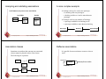
Software Quality
Customer:
solves problems at
an acceptable cost in
terms of money paid and
resources used
User:
easy to learn;
efficient to use;
helps get work done
QUALITY
SOFTWARE
Development manager:
sells more and
pleases customers
while costing less
to develop and maintain
Developer:
easy to design;
easy to maintain;
easy to reuse its parts
© Lethbridge/Laganière 2001
Chapter 1: Software and Software Engineering
14
Internal Quality Criteria
The different qualities can conflict
Increasing efficiency can reduce maintainability or
reusability
Increasing usability can reduce efficiency
These:
Characterize aspects of the design of the software
Have an effect on the external quality attributes
E.g.
—The amount of commenting of the code
—The complexity of the code
Setting objectives for quality is a key engineering
activity
You then design to meet the objectives
Avoids ‘over-engineering’ which wastes money
Optimizing is also sometimes necessary
E.g. obtain the highest possible reliability using a fixed
budget
© Lethbridge/Laganière 2001
Chapter 1: Software and Software Engineering
15
© Lethbridge/Laganière 2001
Chapter 1: Software and Software Engineering
16
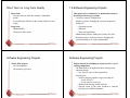
Short Term Vs. Long Term Quality
1.6 Software Engineering Projects
Short term:
Does the software meet the customer’s immediate
needs?
Is it sufficiently efficient for the volume of data we have
today?
Long term:
Maintainability
Customer’s future needs
© Lethbridge/Laganière 2001
Chapter 1: Software and Software Engineering
17
Most projects are evolutionary or maintenance projects,
involving work on legacy systems
Corrective projects: fixing defects
Adaptive projects: changing the system in response to
changes in
—Operating system
—Database
—Rules and regulations
Enhancement projects: adding new features for users
Reengineering or perfective projects: changing the
system internally so it is more maintainable
© Lethbridge/Laganière 2001
Chapter 1: Software and Software Engineering
18
Software Engineering Projects
Software Engineering Projects
‘Green field’ projects
New development
The minority of projects
Projects that involve building on a framework or a set of
existing components.
The framework is an application that is missing some
important details.
—E.g. Specific rules of this organization.
Such projects:
—Involve plugging together components that are:
- Already developed.
- Provide significant functionality.
—Benefit from reusing reliable software.
—Provide much of the same freedom to innovate
found in green field development.
© Lethbridge/Laganière 2001
Chapter 1: Software and Software Engineering
19
© Lethbridge/Laganière 2001
Chapter 1: Software and Software Engineering
20
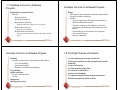
1.7 Activities Common to Software
Projects...
Activities Common to Software Projects...
Requirements and specification
Includes
—Domain analysis
—Defining the problem
—Requirements gathering
- Obtaining input from as many sources as possible
—Requirements analysis
- Organizing the information
—Requirements specification
- Writing detailed instructions about how the software should
behave
© Lethbridge/Laganière 2001
Chapter 1: Software and Software Engineering
21
Activities Common to Software Projects
Chapter 1: Software and Software Engineering
© Lethbridge/Laganière 2001
Chapter 1: Software and Software Engineering
22
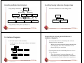
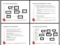
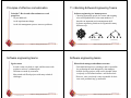
1.8 The Eight Themes of the Book
Modeling
Creating representations of the domain or the software
—Use case modeling
—Structural modeling
—Dynamic and behavioural modeling
Programming
Quality assurance
Reviews and inspections
Testing
Deployment
Managing the process
© Lethbridge/Laganière 2001
Design
Deciding how the requirements should be implemented,
using the available technology
Includes:
—Systems engineering: Deciding what should be in
hardware and what in software
—Software architecture: Dividing the system into
subsystems and deciding how the subsystems will
interact
—Detailed design of the internals of a subsystem
—User interface design
—Design of databases
1. Understanding the customer and the user
2. Basing development on solid principles and reusable
technology
3. Object orientation
4. Visual modeling using UML
5. Evaluation of alternatives
6. Iterative development
7. Communicating effectively using documentation
8. Risk management in all SE activities
23
© Lethbridge/Laganière 2001
Chapter 1: Software and Software Engineering
24
1.9 Difficulties and Risks in Software
Engineering
Complexity and large numbers of details
Uncertainty about technology
Uncertainty about requirements
Uncertainty about software engineering skills
Constant change
Deterioration of software design
Political risks
© Lethbridge/Laganière 2001
Chapter 1: Software and Software Engineering
25
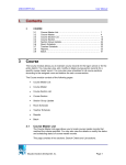
2.1 What is Object Orientation?
Object-Oriented Software Engineering
Practical Software Development using UML and Java
Chapter 2:
Review of Object Orientation
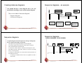
Procedural paradigm:
Software is organized around the notion of procedures
Procedural abstraction
—Works as long as the data is simple
Adding data abstractions
—Groups together the pieces of data that describe
some entity
—Helps reduce the system’s complexity.
- Such as Records and structures
Object oriented paradigm:
Organizing procedural abstractions in the context of data
abstractions
© Lethbridge/Laganière 2001
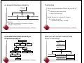
Object Oriented paradigm
Chapter 2: Review of Object Orientation
2
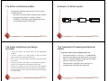
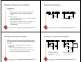
A View of the Two paradigms
An approach to the solution of problems in which all
computations are performed in the context of objects.
main
The objects are instances of classes, which:
—are data abstractions
—contain procedural abstractions that operation on the
objects
A running program can be seen as a collection of objects
collaborating to perform a given task
© Lethbridge/Laganière 2001
Chapter 2: Review of Object Orientation
3
Account
credit
debit
perform transaction
credit
debit
compute interest compute fees
if checking
if checking
then xxx
then xxx
if savings
if savings
then xxx
then xxx
etc.
etc.
© Lethbridge/Laganière 2001
CheckingAccount SavingsAccount
compute interest
compute fees
Chapter 2: Review of Object Orientation
compute interest
compute fees
4
2.2 Classes and Objects
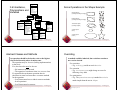
Objects
Object
A chunk of structured data in a running software system
Jane:
date of birth: 1955/02/02
address: 99 UML St.
position: Manager
Greg:
Has properties
—Represent its state
Savings Account 12876:
balance: 1976.32
opened: 1997/03/03
date of birth: 1970/01/01
address: 75 Object Dr.
Margaret:
Has behaviour
—How it acts and reacts
—May simulate the behaviour of an object in the real
world
Mortgage Account 29865:
balance: 198760.00
opened: 2000/08/12
property: 75 Object Dr.
date of birth: 1980/03/03
address: 150 C++ Rd.
position: Teller
Transaction 487:
amount: 200.00
time: 2001/09/01 14:30
Instant Teller 876:
location: Java Valley Cafe
© Lethbridge/Laganière 2001
Chapter 2: Review of Object Orientation
5
Classes
Chapter 2: Review of Object Orientation
6
Is Something a Class or an Instance?
Something should be a class if it could have instances
Something should be an instance if it is clearly a single member of
the set defined by a class
Film
Class; instances are individual films.
Reel of Film:
Class; instances are physical reels
Film reel with serial number SW19876
Instance of ReelOfFilm
Science Fiction
Instance of the class Genre.
Science Fiction Film
Class; instances include ‘Star Wars’
Showing of ‘Star Wars’ in the Phoenix Cinema at 7 p.m.:
Instance of ShowingOfFilm
A class:
Is a unit of abstraction in an object oriented (OO)
program
Represents similar objects
—Its instances
Is a kind of software module
—Describes its instances’ structure (properties)
—Contains methods to implement their behaviour
© Lethbridge/Laganière 2001
© Lethbridge/Laganière 2001
Chapter 2: Review of Object Orientation
7
© Lethbridge/Laganière 2001
Chapter 2: Review of Object Orientation
8
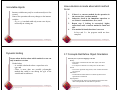
Naming classes
2.3 Instance Variables
Use capital letters
—E.g. BankAccount not bankAccount
Variables defined inside a class corresponding to data
present in each instance
Attributes
—Simple data
—E.g. name, dateOfBirth
Use singular nouns
Use the right level of generality
—E.g. Municipality, not City
Associations
—Relationships to other important classes
—E.g. supervisor, coursesTaken
—More on these in Chapter 5
Make sure the name has only one meaning
—E.g. ‘bus’ has several meanings
© Lethbridge/Laganière 2001
Chapter 2: Review of Object Orientation
9
Variables vs. Objects
© Lethbridge/Laganière 2001
Chapter 2: Review of Object Orientation
10
Class variables
A variable
Refers to an object
May refer to different objects at different points in time
A class variable’s value is shared by all instances of a
class.
Also called a static variable
If one instance sets the value of a class variable, then all
the other instances see the same changed value.
An object can be referred to by several different
variables at the same time
Class variables are useful for:
—Default or ‘constant’ values (e.g. PI)
—Lookup tables and similar structures
Type of a variable
Determines what classes of objects it may contain
Caution: do not over-use class variables
© Lethbridge/Laganière 2001
Chapter 2: Review of Object Orientation
11
© Lethbridge/Laganière 2001
Chapter 2: Review of Object Orientation
12
2.4 Methods, Operations and Polymorphism
Operation
A higher-level procedural abstraction that specifies a
type of behaviour
Independent of any code which implements that
behaviour
—E.g., calculating area (in general)
© Lethbridge/Laganière 2001
Chapter 2: Review of Object Orientation
Method
A procedural abstraction used to implement the
behaviour of a class.
Several different classes can have methods with the
same name
—They implement the same abstract operation in ways
suitable to each class
—E.g, calculating area in a rectangle is done
differently from in a circle
13
© Lethbridge/Laganière 2001
Chapter 2: Review of Object Orientation
14
2.5 Organizing Classes into Inheritance
Hierarchies
Polymorphism
A property of object oriented software by which an
abstract operation may be performed in different ways
in different classes.
Requires that there be multiple methods of the same
name
The choice of which one to execute depends on the
object that is in a variable
Reduces the need for programmers to code many if-else
or switch statements
© Lethbridge/Laganière 2001
Methods, Operations and Polymorphism
Chapter 2: Review of Object Orientation
15
Superclasses
Contain features common to a set of subclasses
Inheritance hierarchies
Show the relationships among superclasses and
subclasses
A triangle shows a generalization
Inheritance
The implicit possession by all subclasses of features
defined in its superclasses
© Lethbridge/Laganière 2001
Chapter 2: Review of Object Orientation
16
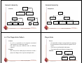
An Example Inheritance Hierarchy
The Isa Rule
Account
SavingsAccount
ChequingAccount
Always check generalizations to ensure they obey the isa
rule
“A checking account is an account”
“A village is a municipality”
MortgageAccount
Should ‘Province’ be a subclass of ‘Country’?
No, it violates the isa rule
—“A province is a country” is invalid!
Inheritance
The implicit possession by all subclasses of features
defined in its superclasses
Chapter 2: Review of Object Orientation
© Lethbridge/Laganière 2001
17
© Lethbridge/Laganière 2001
MathematicalObject
Point
Shape2D
Account
balance
opened
creditOrOverdraftLimit
Matrix
credit
debit
calculateInterest
Shape3D
Ellipse
Polygon
Line
Circle
Quadrilateral
Plane
SavingsAccount
ChequingAccount
highestChequeNumber
withdrawUsingCheque
calculateServiceCharge
Rectangle
© Lethbridge/Laganière 2001
18
Make Sure all Inherited Features Make
Sense in Subclasses
A possible inheritance hierarchy of
mathematical objects
Shape
Chapter 2: Review of Object Orientation
Chapter 2: Review of Object Orientation
19
© Lethbridge/Laganière 2001
MortgageAccount
collateralProperty
collateralValue
setCollateralValue
Chapter 2: Review of Object Orientation
20
Shape2D
2.6 Inheritance,
Polymorphism and
Variables
center
EllipticalShape
Circle
© Lethbridge/Laganière 2001
getBoundingRect
getVertices
Ellipse
SimplePolygon
semiMinorAxis
orientation
rotate
changeScale
getArea
getPerimeterLength
getBoundingRect
getOrientation
getSemiMajorAxis
getSemiMinorAxis
getFocus1
getFocus2
Original objects
(showing bounding rectangle)
Polygon
semiMajorAxis
rotate
changeScale
getArea
getPerimeterLength
getBoundingRect
getRadius
Some Operations in the Shape Example
translate
getCenter
rotate
changeScale
getArea
getPerimeterLength
getBoundingRect
Rotated objects
(showing bounding rectangle)
ArbitraryPolygon
orientation
points
rotate
getOrientation
addPoint
removePoint
rotate
changeScale
getArea
getPerimeterLength
getVertices
Rectangle
RegularPolygon
height
width
numPoints
radius
changeScale
setHeight
setWidth
getArea
getPerimeterLength
getVertices
getBoundingRect
changeNumPoints
changeScale
getArea
getPerimeterLength
getVertices
Chapter 2: Review of Object Orientation
21
© Lethbridge/Laganière 2001
Chapter 2: Review of Object Orientation
22
Overriding
An operation should be declared to exist at the highest
class in the hierarchy where it makes sense
The operation may be abstract (lacking implementation)
at that level
If so, the class also must be abstract
—No instances can be created
—The opposite of an abstract class is a concrete class
If a superclass has an abstract operation then its
subclasses at some level must have a concrete method
for the operation
—Leaf classes must have or inherit concrete methods
for all operations
—Leaf classes must be concrete
Chapter 2: Review of Object Orientation
Scaled objects
(50%)
Scaled objects
(150%)
Abstract Classes and Methods
© Lethbridge/Laganière 2001
Translated objects
(showing original)
23
A method would be inherited, but a subclass contains a
new version instead
For restriction
—E.g. scale(x,y)would not work in Circle
For extension
—E.g. SavingsAccountmight charge an extra fee
following every debit
For optimization
—E.g. The getPerimeterLength method in Circleis
much simpler than the one in Ellipse
© Lethbridge/Laganière 2001
Chapter 2: Review of Object Orientation
24
How a decision is made about which method
to run
Immutable objects
Instance variables may only be set when an object is first
created.
None of the operations allow any changes to the instance
variables
—E.g. a scale method could only create a new object,
not modify an existing one
1.
2.
3.
4.
© Lethbridge/Laganière 2001
Chapter 2: Review of Object Orientation
25
Dynamic binding
© Lethbridge/Laganière 2001
Chapter 2: Review of Object Orientation
26
2.7 Concepts that Define Object Orientation
Occurs when decision about which method to run can
only be made at run time
Needed when:
—A variable is declared to have a superclass as its
type, and
—There is more than one possible polymorphic
method that could be run among the type of the
variable and its subclasses
© Lethbridge/Laganière 2001
If there is a concrete method for the operation in
the current class, run that method.
Otherwise, check in the immediate superclass to
see if there is a method there; if so, run it.
Repeat step 2, looking in successively higher
superclasses until a concrete method is found and
run.
If no method is found, then there is an error
In Java and C++ the program would not have
compiled
Chapter 2: Review of Object Orientation
27
Necessary for a system or language to be OO
Identity
—Each object is distinct from each other object, and can be
referred to
—Two objects are distinct even if they have the same data
Classes
—The code is organized using classes, each of which describes a
set of objects
Inheritance
—The mechanism where features in a hierarchy inherit from
superclasses to subclasses
Polymorphism
—The mechanism by which several methods can have the same
name and implement the same abstract operation.
© Lethbridge/Laganière 2001
Chapter 2: Review of Object Orientation
28
Other Key Concepts
The Basics of Java
History
The first object oriented programming language was Simula-67
—designed to allow programmers to write simulation programs
In the early 1980’s, Smalltalk was developed at Xerox PARC
—New syntax, large open-source library of reusable code,
bytecode, platform independence, garbage collection.
late 1980’s, C++ was developed by B. Stroustrup,
—Recognized the advantages of OO but also recognized that there
were tremendous numbers of C programmers
In 1991, engineers at Sun Microsystems started a project to design a
language that could be used in consumer ‘smart devices’: Oak
—When the Internet gained popularity, Sun saw an opportunity to
exploit the technology.
—The new language, renamed Java, was formally presented in
1995 at the SunWorld ’95 conference.
Abstraction
Object -> something in the world
Class -> objects
Superclass -> subclasses
Operation -> methods
Attributes and associations -> instance variables
Modularity
Code can be constructed entirely of classes
Encapsulation
Details can be hidden in classes
This gives rise to information hiding:
—Programmers do not need to know all the details of a class
© Lethbridge/Laganière 2001
Chapter 2: Review of Object Orientation
29
Java documentation
Chapter 2: Review of Object Orientation
30
Overview of Java
Looking up classes and methods is an essential skill
Looking up unknown classes and methods will get you a
long way towards understanding code
Java documentation can be automatically generated by
a program called Javadoc
Documentation is generated from the code and its
comments
You should format your comments as shown in some of
the book’s examples
—These may include embeded html
© Lethbridge/Laganière 2001
© Lethbridge/Laganière 2001
Chapter 2: Review of Object Orientation
31
The next few slides will remind you of several key Java
features
Not in the book
See the book’s web site for
—A more detailed overview of Java
—Pointers to tutorials, books etc.
© Lethbridge/Laganière 2001
Chapter 2: Review of Object Orientation
32
Characters and Strings
Arrays and Collections
Arrays are of fixed size and lack methods to manipulate them
Characteris a class representing Unicode characters
More than a byte each
Represent any world language
Vector is the most widely used class to hold a collection of other
objects
More powerful than arrays, but less efficient
char is a primitive data type containing a Unicode
character
Iterators are used to access members of Vectors
• Enu merations were formally used, but were more complex
v = new Vector();
String is a class containing collections of characters
+ is the operator used to concatenate strings
© Lethbridge/Laganière 2001
Chapter 2: Review of Object Orientation
Iteratori = v.iterator();
while(i.hasNext())
{
aMethod(v.next());
}
33
Casting
Chapter 2: Review of Object Orientation
34
Exceptions
Java is very strict about types
If a variable is declared to have the type X, you can only
invoke operations on it that are defined in class X or its
superclasses
—Even though an instance of a subclass of X may be
actually stored in the variable
If you know an instance of a subclass is stored, then you
can cast the variable to the subclass
—E.g. if I know a Vectorcontains instances of String,
I can get the next element of its Iterator using:
(String)iterator.next();
© Lethbridge/Laganière 2001
© Lethbridge/Laganière 2001
Chapter 2: Review of Object Orientation
35
Anything that can go wrong should result in the raising
of an Exception
•Exception is a class with many subclasses for specific
things that can go wrong
Use a try - catch block to trap an exception
try
{
// some code
}
catch (ArithmeticException e)
{
// code to handle division by zero
}
© Lethbridge/Laganière 2001
Chapter 2: Review of Object Orientation
36
Interfaces
Packages and importing
Like abstract classes, but cannot have executable
statements
Define a set of operations that make sense in several
classes
Abstract Data Types
A class can implement any number of interfaces
It must have concrete methods for the operations
You can declare the type of a variable to be an interface
This is just like declaring the type to be an abstract class
Important interfaces in Java’s library include
•Runnable, Collection, Iterator, Comparable,
Cloneable
© Lethbridge/Laganière 2001
Chapter 2: Review of Object Orientation
37
Access control
Classes in different packages can have the same name
Although not recommended
Importing a package is done as follows:
importfinance.banking.accounts.*;
© Lethbridge/Laganière 2001
Chapter 2: Review of Object Orientation
38
Threads and concurrency
Applies to methods and variables
•public
—Any class can access
•protected
—Only code in the package, or subclasses can access
(blank)
—Only code in the package can access
•private
—Only code written in the class can access
—Inheritance still occurs!
© Lethbridge/Laganière 2001
A package combines related classes into subsystems
All the classes in a particular directory
Chapter 2: Review of Object Orientation
Thread:
Sequence of executing statements that can be running
concurrently with other threads
To create a thread in Java:
1. Create a class implementing Runnable or extending
Thread
2. Implement the run method as a loop that does
something for a period of time
3. Create an instance of this class
4. Invoke the startoperation, which calls run
39
© Lethbridge/Laganière 2001
Chapter 2: Review of Object Orientation
40
Programming Style Guidelines
Programming style …
Remember that programs are for people to read
Always choose the simpler alternative
Reject clever code that is hard to understand
Shorter code is not necessarily better
Comment extensively
Comment whatever is non-obvious
Do not comment the obvious
Comments should be 25-50% of the code
Choose good names
Make them highly descriptive
Do not worry about using long names
Organize class elements consistently
Variables, constructors, public methods then private
methods
Be consistent regarding layout of code
© Lethbridge/Laganière 2001
Chapter 2: Review of Object Orientation
41
Chapter 2: Review of Object Orientation
42
Programming style ...
Programming style …
Avoid duplication of code
Do not ‘clone’ if possible
—Create a new method and call it
—Cloning results in two copies that may both have
bugs
- When one copy of the bug is fixed, the other may
be forgotten
© Lethbridge/Laganière 2001
© Lethbridge/Laganière 2001
Chapter 2: Review of Object Orientation
43
Adhere to good object oriented principles
E.g. the ‘isa rule’
Prefer private as opposed to public
Do not mix user interface code with non-user interface
code
Interact with the user in separate classes
—This makes non-UI classes more reusable
© Lethbridge/Laganière 2001
Chapter 2: Review of Object Orientation
44
2.10 Difficulties and Risks in ObjectOriented Programming
Language evolution and deprecated features:
Java can be less efficient than other languages
—VM-based
—Dynamic binding
Efficiency can be a concern in some object oriented
systems
Java is evolving, so some features are ‘deprecated’ at
every release
But the same thing is true of most other languages
© Lethbridge/Laganière 2001
Chapter 2: Review of Object Orientation
45
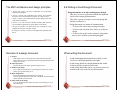
3.1 Building on the Experience of Others
Software engineers should avoid re-developing software
already developed
Object-Oriented Software Engineering
Practical Software Development using UML and Java
Types of reuse:
Reuse of expertise
Reuse of standard designs and algorithms
Reuse of libraries of classes or procedures
Reuse of powerful commands built into languages and
operating systems
Reuse of frameworks
Reuse of complete applications
Chapter 3:
Basing Software Development on
Reusable Technology
© Lethbridge/Laganière 2001
3.2 Reusability and Reuse in SE
Developers tend not develop high quality reusable
components, so there is often little to reuse
But there are problems to overcome:
Why take the extra time needed to develop something
that will benefit other projects/customers?
Management may only reward the efforts of people who
create the visible ‘final products’.
Reusable software are often created in a hurry and
without enough attention to quality.
Chap. 3: Basing Development on Reusable
Technology
2
A vicious cycle
Reuse and design for reusability should be part of the
culture of software development organizations
© Lethbridge/Laganière 2001
Chap. 3: Basing Development on Reusable
Technology
3
To solve the problem, recognize that:
This vicious cycle costs money
Investment in reusable code is important
Attention to quality of reusable components is essential
—So that potential reusers have confidence in them
—The quality of a software product is only as good as
its lowest-quality reusable component
Developing reusable components can often simplify
design
© Lethbridge/Laganière 2001
Chap. 3: Basing Development on Reusable
Technology
4
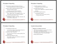
3.3 Frameworks: Reusable Subsystems
Frameworks to promote reuse
A framework is reusable software that implements a
generic solution to a generalized problem.
It provides common facilities applicable to different
application programs.
Principle: Applications that do different, but related,
things tend to have quite similar designs
A framework is intrinsically incomplete
Certain classes or methods are used by the framework,
but are missing (slots)
Some functionality is optional
— Allowance is made for developer to provide it
(hooks)
Developers use the services that the framework provides
—Taken together the services are called the
Application Program Interface (API)
© Lethbridge/Laganière 2001
Chap. 3: Basing Development on Reusable
Technology
5
Object-oriented frameworks
© Lethbridge/Laganière 2001
Chap. 3: Basing Development on Reusable
Technology
6
Examples of frameworks
In the object oriented paradigm, a framework is
composed of a library of classes.
The API is defined by the set of all public methods of
these classes.
Some of the classes will normally be abstract
A framework for payroll management
A framework for frequent buyer clubs
A framework for university registration
A framework for e-commerce web sites
A framework for controlling microwave ovens
© Lethbridge/Laganière 2001
Chap. 3: Basing Development on Reusable
Technology
7
© Lethbridge/Laganière 2001
Chap. 3: Basing Development on Reusable
Technology
8
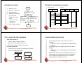
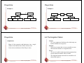
Types of frameworks
3.4 The Client-Server Architecture
A horizontal framework provides general application facilities
that a large number of applications can use
A vertical framework (application framework) is more
‘complete’ but still needs some slots to be filled to adapt it to
specific application needs
Application
Services offered
by the framework
Application
Horizontal framework
Vertical
framework
A distributed system is a system in which:
computations are performed by separate programs
… normally running on separate pieces of hardware
… that co-operate to perform the task of the system.
Server:
A program that provides a service for other programs
that connect to it using a communication channel
Client
A program that accesses a server (or several servers) to
obtain services
A server may be accessed by many clients
simultaneously
Code to be provided to adapt the framework to the
needs of the application
© Lethbridge/Laganière 2001
Chap. 3: Basing Development on Reusable
Technology
9
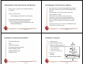
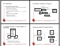
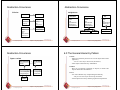
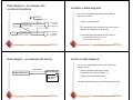
Sequence of activities in a client-server
system
Chap. 3: Basing Development on Reusable
Technology
10
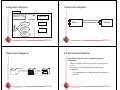
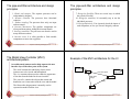
A server program communicating with two
client programs
1. The server starts running
2. The server waits for clients to connect. (listening)
3. Clients start running and perform operations
— Some operations involve requests to the server
4. When a client attempts to connect, the server accepts
the connection (if it is willing)
5. The server waits for messages to arrive from
connected clients
6. When a message from a client arrives, the server
takes some action in response, then resumes waiting
7. Clients and servers continue functioning in this
manner until they decide to shut down or disconnect
© Lethbridge/Laganière 2001
Chap. 3: Basing Development on Reusable
Technology
© Lethbridge/Laganière 2001
11
Application
Services offered
by the framework
Application
Horizontal framework
Vertical
framework
Code to be provided to adapt the framework to the
needs of the application
© Lethbridge/Laganière 2001
Chap. 3: Basing Development on Reusable
Technology
12
Alternatives to the client server architecture
Advantages of client-server systems
The work can be distributed among different machines
The clients can access the server’s functionality from a
distance
The client and server can be designed separately
They can both be simpler
All the data can be kept centrally at the server
Conversely, data can be distributed among many
different geographically-distributed clients or servers
The server can be accessed simultaneously by many
clients
Competing clients can be written to communicate with
the same server, and vice-versa
Have a single program on one computer that does
everything
Have no communication
— Each computer performs the work separately
Have some mechanism other than client-server
communication for exchanging information
—E.g. one program writes to a database; the other
reads from the database
© Lethbridge/Laganière 2001
Chap. 3: Basing Development on Reusable
Technology
13
Example of client-server systems
© Lethbridge/Laganière 2001
Chap. 3: Basing Development on Reusable
Technology
14
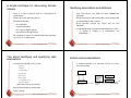
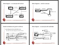
Activities of a server
1. Initializes itself
2. Starts listening for clients
Initializing
3. Handles the following types of
events originating from clients For the server as a whole:
The World Wide Web
Email
Network File System
Transaction Processing System
Remote Display System
Communication System
Database System
1.
2.
3.
accepts connections
responds to messages
handles client disconnection
4. May stop
listening
1. Must cleanly terminate
Waiting
start listening
stop listening
Waiting for Connections
accept connection
For each connection:
Handling a Connection
handle
disconnection
do: react to messages
terminate
© Lethbridge/Laganière 2001
Chap. 3: Basing Development on Reusable
Technology
15
© Lethbridge/Laganière 2001
Chap. 3: Basing Development on Reusable
Technology
16
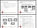
Activities of a client
1.
2.
3.
4.
1.
2.
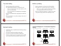
Threads in a client-server system
interact
with user
connect
interact with the
user,
sending messages
to the server
as necessary
do: respond to messages
and
handle server
disconnection
wait for
messages:
client B
interact with
server user
create
display reply
send message
reply to message
display reply
kill client
display
disconnect
17
Heavy computation
requests
for services
Chap. 3: Basing Development on Reusable
Technology
18
The messages the client sends to the server form a
language.
— The server has to be programmed to understand that
language.
The messages the server sends to the client also form a
language.
— The client has to be programmed to understand that
language.
When a client and server are communicating, they are in
effect having a conversation using these two languages
The two languages and the rules of the conversation,
taken together, are called the protocol
Light computation
Heavy computation
© Lethbridge/Laganière 2001
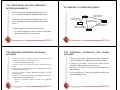
Communications protocols
Thin-client system (a)
Client is made as small as possible
Most of the work is done in the server.
Client easy to download over the network
Fat-client system (b)
As much work as possible is delegated to the clients.
Server can handle more clients
results
for display
disconnect
terminate
Thin- versus fat-client systems
© Lethbridge/Laganière 2001
wait for
messages:
client A
reply to message
respond to events
triggered by the server
Chap. 3: Basing Development on Reusable
Technology
a
wait for
connections
send message
5. Must cleanly terminate
simple
commands
wait for server
events
Server Side
create
initiate a connection
to a server
responds to messages
handles server
disconnection
© Lethbridge/Laganière 2001
Client Side (Client A)
initialize
Initializes itself
Initiates a connection
Sends messages
Handles the following
types of events
originating from the
server
results
of requests
Light computation
b
Chap. 3: Basing Development on Reusable
Technology
19
© Lethbridge/Laganière 2001
Chap. 3: Basing Development on Reusable
Technology
20
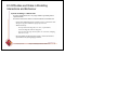
Tasks to perform to develop
client-server applications
3.5 Technology Needed to Build ClientServer Systems
1. Design the primary work to be performed by both client
and server
2. Design how the work will be distributed
3. Design the details of the set of messages that will be sent
4. Design the mechanism for
1.
2.
3.
4.
Initializing
Handling connections
Sending and receiving messages
Terminating
© Lethbridge/Laganière 2001
Chap. 3: Basing Development on Reusable
Technology
21
Establishing a connection in Java
Before a connection can be established, the server must
start listening to one of the ports:
ServerSocket serverSocket = new
ServerSocket(port);
Socket clientSocket = serverSocket.accept();
Chap. 3: Basing Development on Reusable
Technology
22
Each program uses an instance of
—InputStream to receive messages from the other
program
— OutputStream to send messages to the other
program
—These are found in package java.io
output = new
OutputStream(clientSocket.getOutputStream());
For a client to connect to a server:
input = new
InputStream(clientSocket.getInputStream());
Socket clientSocket= new Socket(host,port);
Chap. 3: Basing Development on Reusable
Technology
© Lethbridge/Laganière 2001
Exchanging information in Java
The java.net package
Permits the creation of a TCP/IP connection between
two applications
© Lethbridge/Laganière 2001
Internet Protocol (IP)
Route messages from one computer to another
Long messages are normally split up into small pieces
Transmission Control Protocol (TCP)
Handles connections between two computers
Computers can then exchange many IP messages over a connection
Assures that the messages have been satisfactorily received
A host has an IP address and a host name
Several servers can run on the same host.
Each server is identified by a port number (0 to 65535).
To initiate communication with a server, a client must know both
the host name and the port number
23
© Lethbridge/Laganière 2001
Chap. 3: Basing Development on Reusable
Technology
24
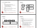
3.6 The Object Client-Server Framework
(OCSF)
Sending and receiving messages
without any filters
output.write(msg);
msg = input.read();
or using DataInputStream / DataInputStrea m filters
output.writeDouble(msg);
msg = input.readDouble();
AbstractClient
AbstractServer
openConnection
sendToServer
closeConnection
connectionClosed
connectionException
connectionEstablished
handleMessageFromServer
listen
stopListening
close
sendToAllClients
getClientConnections
clientConnected
clientDisconnected
clientException
serverStarted
serverStopped
listeningException
serverClosed
handleMessageFromClient
or using ObjectInputStrea m / ObjectInputStrea m filters
output.writeObject(msg);
msg = input.readObject();
© Lethbridge/Laganière 2001
Chap. 3: Basing Development on Reusable
Technology
25
Using OCSF
sendToClient
close
setInfo
getInfo
Chap. 3: Basing Development on Reusable
Technology
26
3.7 The Client Side
Software engineers using OCSF never modify its three
classes
Consists of a single class: AbstractClient
Must be subclassed
—Any subclass must provide an implementation for
handleMessageFromServer
They:
Create subclasses of the abstract classes in the
framework
- Takes appropriate action when a message is received from a
server
Call public methods that are provided by the framework
Chap. 3: Basing Development on Reusable
Technology
Implements the Runnableinterface
—Has a run method which
- Contains a loop that executes for the lifetime of the thread
Override certain slot and hook methods (explicitly
designed to be overridden)
© Lethbridge/Laganière 2001
© Lethbridge/Laganière 2001
ConnectionToClient
*
27
© Lethbridge/Laganière 2001
Chap. 3: Basing Development on Reusable
Technology
28
The public interface of AbstractClient
The callback methods of AbstractClient
Controlling methods:
•openConnection
•closeConnection
•sendToServer
Accessing methods:
•isConnected
•getHost
•setHost
•getPort
•setPort
•getInetAddress
© Lethbridge/Laganière 2001
Methods that may be overridden:
•connectionEstablished
•connectionClosed
Method that must be overridden:
•handleMessageFrom Server
Chap. 3: Basing Development on Reusable
Technology
29
Using AbstractClient
Chap. 3: Basing Development on Reusable
Technology
30
Internals of AbstractClient
Create a subclass of AbstractClient
Implement handleMessageFrom Server slot method
Write code that:
—Creates an instance of the new subclass
—Calls openConnection
—Sends messages to the server using the
sendToServer service method
Implement the connectionClosed callback
Implement the connectionException callback
© Lethbridge/Laganière 2001
© Lethbridge/Laganière 2001
Chap. 3: Basing Development on Reusable
Technology
31
Instance variables:
A Socket which keeps all the information about the
connection to the server
Two streams, an ObjectOutputStrea m and an
ObjectInputStrea m
A Thread that runs using AbstractClient’s run
method
Two variables storing the host and port of the server
© Lethbridge/Laganière 2001
Chap. 3: Basing Development on Reusable
Technology
32
3.8 The Server Side
The public interface of AbstractServer
Two classes:
One for the thread which listens for new connections
(AbstractServer)
One for the threads that handle the connections to clients
(ConnectionToClient)
© Lethbridge/Laganière 2001
Chap. 3: Basing Development on Reusable
Technology
33
The callback methods of AbstractServer
Chap. 3: Basing Development on Reusable
Technology
© Lethbridge/Laganière 2001
Chap. 3: Basing Development on Reusable
Technology
34
The public interface of ConnectionToClient
Methods that may be overridden:
•serverStarted
•clientConnected
•clientDisconnected
•clientException
•serverStopped
•listeningException
•serverClosed
Method that must be overridden:
•handleMessageFrom Client
© Lethbridge/Laganière 2001
Controlling methods:
•listen
•stopListening
•close
•sendToAllClients
Accessing methods:
•isListening
•getClientConnections
•getPort
•setPort
•setBacklog
Controlling methods:
•sendToClient
•close
Accessing methods:
•getInetAddress
•setInfo
•getInfo
35
© Lethbridge/Laganière 2001
Chap. 3: Basing Development on Reusable
Technology
36
Using AbstractServer and
ConnectionToClient
Internals of AbstractServer and
ConnectionToClient
Create a subclass of AbstractServer
Implement the slot method
handleMessageFrom Client
Write code that:
— Creates an instance of the subclass of
AbstractClient
— Calls the listen method
— Sends messages to clients, using:
-
The setInfo and getInfo methods make use of a Java
class called Hash Map
Many methods in the server side are synchronized
The collection of instances of ConnectionToClient is
stored using a special class called ThreadGroup
the getClientConnections and sendToClient service
methods
or sendToAllClients
Implement one or more of the other callback methods
© Lethbridge/Laganière 2001
Chap. 3: Basing Development on Reusable
Technology
37
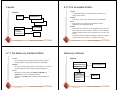
3.11 An Instant Messaging Application:
SimpleChat
<<interface>>
ChatIF
AbstractClient
ChatClient
ClientConsole
accept
display
main
AbstractServer
EchoServer
handleMessageFromClient
serverStarted
serverStopped
main
ClientConsole can eventually be replaced by ClientGUI
© Lethbridge/Laganière 2001
Chap. 3: Basing Development on Reusable
Technology
© Lethbridge/Laganière 2001
Chap. 3: Basing Development on Reusable
Technology
38
The server
display
handleMessageFromServer
handleMessageFromClientUI
quit
The server must pause from listening every 500ms to see
if the stopListening method has been called
—if not, then it resumes listening immediately
39
EchoServer is a subclass of AbstractServer
The main method creates a new instance and starts it
— It listens for clients and handles connections until
the server is stopped
The three callback methods just print out a message to
the user
— handleMessageFrom Client, serverStarted
and serverStopped
The slot method handleMessageFrom Clientcalls
sendToAllClients
— This echoes any messages
© Lethbridge/Laganière 2001
Chap. 3: Basing Development on Reusable
Technology
40
Key code in EchoServer
The client
When the client program starts, it creates instances of two classes:
• ChatClient
—A subclass of AbstractClient
—Overrides handleMessageFro mServer
public void handleMessageFrom Client
(Object m sg, ConnectionToClient client)
{
System.out.println(
"Message received: "
+ msg + " from " + client);
this.sendToAllClients(msg);
}
- This calls the display method of the user interface
• ClientConsole
—User interface class that implements the interface ChatIF
- Hence implements display which outputs to the console
—Accepts user input by calling accept in its run method
—Sends all user input to the ChatClient by calling its
handleMessageFro m ClientUI
- This, in turn, calls sendToServer
© Lethbridge/Laganière 2001
Chap. 3: Basing Development on Reusable
Technology
41
Key code in ChatClient
Chap. 3: Basing Development on Reusable
Technology
Chap. 3: Basing Development on Reusable
Technology
42
Key code in ChatClient - continued
public void handleMessageFro m ClientUI(
String message)
{
try
{
sendToServer(message);
}
catch(IOException e)
{
clientUI.display (
"Could not send message. " +
"Terminating client.");
quit();
}
}
© Lethbridge/Laganière 2001
© Lethbridge/Laganière 2001
public void handleMessageFro mServer(Object msg)
{
clientUI.display(msg.toString());
}
43
© Lethbridge/Laganière 2001
Chap. 3: Basing Development on Reusable
Technology
44
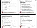
3.12 Risks when reusing technology
Risks when developing reusable technology
Investment uncertainty
—Plan the development of the reusable technology, just
as if it was a product for a client
Poor quality reusable components
—Ensure that the developers of the reusable
technology:
- follow good software engineering practices
- are willing to provide active support
Compatibility not maintained
—Avoid obscure features
—Only re-use technology that others are also re-using
© Lethbridge/Laganière 2001
Chap. 3: Basing Development on Reusable
Technology
45
Risk when developing reusable technology –
continued
The ‘not invented here syndrome’
—Build confidence in the reusable technology by:
- Guaranteeing support
- Ensuring it is of high quality
- Responding to the needs of its users
© Lethbridge/Laganière 2001
Chap. 3: Basing Development on Reusable
Technology
46
Risks when adopting a client-server
approach
Competition
—The reusable technology must be as useful and as
high quality as possible
Security
—Security is a big problem with no perfect solutions:
consider the use of encryption, firewalls, ...
Divergence (tendency of various groups to change
technology in different ways)
—Design it to be general enough, test it and review it
in advance
Need for adaptive maintenance
—Ensure that all software is forward and backward
compatible with other versions of clients and servers
© Lethbridge/Laganière 2001
Chap. 3: Basing Development on Reusable
Technology
47
© Lethbridge/Laganière 2001
Chap. 3: Basing Development on Reusable
Technology
48
4.1 Domain Analysis
Object-Oriented Software Engineering
Practical Software Development using UML and Java
Chapter 4:
Developing Requirements
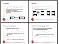
The process by which a software engineer learns about
the domain to better understand the problem:
The domain is the general field of business or
technology in which the clients will use the software
A domain expert is a person who has a deep knowledge
of the domain
Benefits of performing domain analysis:
Faster development
Better system
Anticipation of extensions
Chapter 4: Developing requirements
© Lethbridge/Laganière 2001
Domain Analysis document
A.
B.
C.
D.
E.
F.
G.
H.
4.2 The Starting Point for Software Projects
Introduction
Glossary
General knowledge about the domain
Customers and users
The environment
Tasks and procedures currently performed
Competing software
Similarities to other domains
© Lethbridge/Laganière 2001
Chapter 4: Developing requirements
2
Clients have produced
Requirements
requirements
must be determined
New
development
A
B
C
D
green field project
Evolution of
existing system
3
© Lethbridge/Laganière 2001
Chapter 4: Developing requirements
4
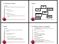
4.3 Defining the Problem and the Scope
Defining the Scope
A problem can be expressed as:
A difficulty the users or customers are facing,
Or as an opportunity that will result in some benefit such
as improved productivity or sales.
Narrow the scope by defining a more precise problem
List all the things you might imagine the system doing
—Exclude some of these things if too broad
—Determine high-level goals if too narrow
The solution to the problem normally will entail
developing software
Example: A university registration system
Initial list of problems
with very broad scope
A good problem statement is short and succinct
browsing courses
registering
Narrowed
scope
room allocation
exam scheduling
fee payment
© Lethbridge/Laganière 2001
Chapter 4: Developing requirements
5
4.4 What is a Requirement
© Lethbridge/Laganière 2001
browsing courses
registering
Scope of
another system
room allocation
exam scheduling
fee payment
Chapter 4: Developing requirements
6
4.5 Types of Requirements
Requirement: A statement about the proposed system
that all stakeholders agree must be made true in order
for the customer’s problem to be adequately solved.
Short and concise piece of information
Says something about the system
All the stakeholders have agreed that it is valid
It helps solve the customer’s problem
Functional requirements
Describe what the system should do
Non-functional requirements
Constraints that must be adhered to during development
A collection of requirements is a requirements document.
© Lethbridge/Laganière 2001
Chapter 4: Developing requirements
7
© Lethbridge/Laganière 2001
Chapter 4: Developing requirements
8
Functional requirements
Non-functional requirements
All must be verifiable
Three main types
1. Categories reflecting: usability, efficiency, reliability,
maintainability and reusability
—Response time
—Throughput
—Resource usage
—Reliability
—Availability
—Recovery from failure
—Allowances for maintainability and enhancement
—Allowances for reusability
What inputs the system should accept
What outputs the system should produce
What data the system should store that other systems
might use
What computations the system should perform
The timing and synchronization of the above
© Lethbridge/Laganière 2001
Chapter 4: Developing requirements
9
10
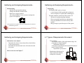
Observation
Read documents and discuss requirements with users
Shadowing important potential users as they do their work
—ask the user to explain everything he or she is doing
Session videotaping
Interviewing
Conduct a series of interviews
—Ask about specific details
—Ask about the stakeholder’s vision for the future
—Ask if they have alternative ideas
—Ask for other sources of information
—Ask them to draw diagrams
2. Categories constraining the environment and
technology of the system.
—Platform
—Technology to be used
3. Categories constraining the project plan and
development methods
—Development process (methodology) to be used
—Cost and delivery date
- Often put in contract or project plan instead
Chapter 4: Developing requirements
Chapter 4: Developing requirements
4.6 Some Techniques for Gathering and
Analysing Requirements
Non-functional requirements
© Lethbridge/Laganière 2001
© Lethbridge/Laganière 2001
11
© Lethbridge/Laganière 2001
Chapter 4: Developing requirements
12
Gathering and Analysing Requirements...
Gathering and Analysing Requirements...
Brainstorming
Appoint an experienced moderator
Arrange the attendees around a table
Decide on a ‘trigger question’
Ask each participant to write an answer and pass the
paper to its neighbour
!
!
!
!
!
!
Joint Application Development (JAD) is a technique based on intensive
brainstorming sessions
© Lethbridge/Laganière 2001
Chapter 4: Developing requirements
13
Gathering and Analysing Requirements...
Prototyping
The simplest kind: paper prototype.
—a set of pictures of the system that are shown to
users in sequence to explain what would happen
The most common: a mock-up of the system’s UI
—Written in a rapid prototyping language
—Does not normally perform any computations,
access any databases or interact with any other
systems
—May prototype a particular aspect of the system
© Lethbridge/Laganière 2001
Chapter 4: Developing requirements
14
4.7 Types of Requirements Document
Informal use case analysis
Determine the classes of users that will use the facilities
of this system (actors)
Determine the tasks that each actor will need to do with
the system
Two extremes:
An informal outline of the requirements using a few
paragraphs or simple diagrams
requirements definition
A long list of specifications that contain thousands of
pages of intricate detail
requirements specification
More on use cases in Chapter 7
Requirements documents for
large systems are normally
arranged in a hierarchy
Requirements
xxxx
xxxxxxx
xxx
xxxxxxxxxxx
xxxxx
xxxxxxxxxxxxx
xxxxxxx
xxx
xxxxxxxxxxxxxxx
subsystem 1
Requirements
xxxx
xxxxxxx
xxx
xxxxxxxxxxx
xxxxx
xxxxxxxxxxxxx
xxxxxxx
xxx
xxxxxxxxxxxxxxx
sub-subsystems
Requirements
Requirements Requirements
Requirements
Definition
Definition
Definition
Definition
xxxx
xxxx
xxxxxxx
xxxx
xxxxxxx
xxxx
xxx Requirements
xxxxxxx
xxx Requirements
xxxxxxx
xxx Requirements
xxxxxxxxxxx xxxxxxxxxxx
xxx Requirements
xxxxx Specification
xxxxx Specification
xxxxxxxxxxx xxxxxxxxxxx
Specification
xxxx
xxxxxxxxxxxxx
xxxxx
xxxxxxxxxxxxx
xxxxx Specification
xxxx
xxxxxxx
xxxx
xxxxxxxxxxxxx
xxxxxxxxxxxxx
xxxxxxx xxxxxxx
xxxx
xxxxxxx xxxxxxx
xxx xxx
xxx xxx
xxxxxxx
xxxxxxx xxxxxxx
xxxxxxxxxxx
xxx
xxxxxxxxxxxxxxx
xxx
xxxxxxxxxxxxxxx
xxx xxx
xxxxxxxxxxx
xxxxx
xxxxxxxxxxx
xxxxxxxxxxxxxxx
xxxxxxxxxxxxxxx
xxxxx
xxxxxxxxxxx
xxxxxxxxxxxxx
xxxxx
xxxxx
xxxxxxxxxxxxx xxxxxxxxxxxxx xxxxxxx
xxxxxxx
xxxxxxxxxxxxx xxxxxxx
xxx
xxx
xxxxxxx
xxxxxxxxxxxxxxx
xxx
xxx
xxxxxxxxxxxxxxxxxxxxxxxxxxxxxx
xxxxxxxxxxxxxxx
© Lethbridge/Laganière 2001
Chapter 4: Developing requirements
15
© Lethbridge/Laganière 2001
Chapter 4: Developing requirements
subsystem 2
Requirements
Definition
xxxx
xxxxxxx
Requirements
xxx
xxxxxxxxxxx
Specification
xxxxx
xxxx
xxxxxxxxxxxxx
xxxxxxxxxxxxxx
xxx
xxx
xxxxxxxxxxx
xxxxxxxxxxxxxxx
xxxxx
xxxxxxxxxxxxx
xxxxxxx
xxx
xxxxxxxxxxxxxxx
sub-subsystems
Requirements
Requirements Requirements
Definition
Requirements
Definition
Definition
xxxx
Definition
xxxx
xxxxxxx
xxxx
xxxx
xxxxxxx
xxx Requirements
xxxxxxx
xxx Requirements
xxxxxxx
xxx Requirements
xxx Requirements
xxxxxxxxxxx xxxxxxxxxxx
Specification
xxxxx
xxxxx Specification
xxxxxxxxxxx xxxxxxxxxxx
Specification
xxxx
xxxxxxxxxxxxx
xxxxx
xxxxx Specification
xxxxxxxxxxxxx
xxxx
xxxxxxx
xxxx
xxxxxxxxxxxxx
xxxxxxxxxxxxx
xxxx
xxxxxxx xxxxxxx
xxxxxxx xxxxxxx
xxx xxx
xxxxxxx
xxx xxx
xxxxxxx xxxxxxx
xxxxxxxxxxx
xxx xxx
xxxxxxxxxxxxxxx
xxx xxx
xxxxxxxxxxxxxxx
xxxxxxxxxxx
xxxxx
xxxxxxxxxxx
xxxxxxxxxxxxxxx
xxxxxxxxxxxxxxx
xxxxxxxxxxx
xxxxx
xxxxxxxxxxxxx
xxxxx
xxxxx
xxxxxxxxxxxxx xxxxxxxxxxxxx xxxxxxx
xxxxxxxxxxxxx xxxxxxx
xxxxxxx
xxx
xxxxxxx
xxx
xxxxxxxxxxxxxxx
xxx
xxx
xxxxxxxxxxxxxxxxxxxxxxxxxxxxxx
xxxxxxxxxxxxxxx
16
Level of detail required in a requirements
document
4.8 Reviewing Requirements
How much detail should be provided depends on:
—The size of the system
—The need to interface to other systems
—The readership
—The stage in requirements gathering
—The level of experience with the domain and the
technology
—The cost that would be incurred if the requirements
were faulty
Chapter 4: Developing requirements
© Lethbridge/Laganière 2001
Each individual requirement should
—Have benefits that outweigh the costs of development
—Be important for the solution of the current problem
—Be expressed using a clear and consistent notation
—Be unambiguous
—Be logically consistent
—Lead to a system of sufficient quality
—Be realistic with available resources
—Be verifiable
—Be uniquely identifiable
—Does not over-constrain the design of the system
17
Requirements documents...
© Lethbridge/Laganière 2001
Chapter 4: Developing requirements
18
Requirements document...
The document should be:
—sufficiently complete
—well organized
—clear
—agreed to by all the stakeholders
A.
B.
C.
D.
E.
Problem
Background information
Environment and system models
Functional Requirements
Non-functional requirements
Traceability:
Requirements
document
rationale
© Lethbridge/Laganière 2001
1.1 XXXX
.... because
1.2 YYYY
Design
document
....due to
requirement 1.2
Chapter 4: Developing requirements
19
© Lethbridge/Laganière 2001
Chapter 4: Developing requirements
20
4.13 Difficulties and Risks in Domain and
Requirements Analysis
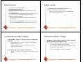
4.9 Managing Changing Requirements
Requirements change because:
Business process changes
Technology changes
The problem becomes better understood
Requirements analysis never stops
Continue to interact with the clients and users
The benefits of changes must outweigh the costs.
—Certain small changes (e.g. look and feel of the UI) are usually
quick and easy to make at relatively little cost.
—Larger-scale changes have to be carefully assessed
- Forcing unexpected changes into a partially built system will
probably result in a poor design and late delivery
Some changes are enhancements in disguise
—Avoid making the system bigger, only make it better
© Lethbridge/Laganière 2001
Chapter 4: Developing requirements
21
Lack of understanding of the domain or the real problem
—Do domain analysis and prototyping
Requirements change rapidly
—Perform incremental development, build flexibility into the
design, do regular reviews
Attempting to do too much
—Document the problem boundaries at an early stage, carefully
estimate the time
It may be hard to reconcile conflicting sets of requirements
—Brainstorming, JAD sessions, competing prototypes
It is hard to state requirements precisely
—Break requirements down into simple sentences and review
them carefully, look for potential ambiguity, make early
prototypes
© Lethbridge/Laganière 2001
Chapter 4: Developing requirements
22
5.1 What is UML?
Object-Oriented Software Engineering
Practical Software Development using UML and Java
Chapter 5:
Modelling with Classes
The Unified Modelling Language is a standard graphical language
for modelling object oriented software
At the end of the 1980s and the beginning of 1990s, the first objectoriented development processes appeared
The proliferation of methods and notations tended to cause
considerable confusion
Two important methodologists Rumbaugh and Booch decided to
merge their approaches in 1994.
—They worked together at the Rational Software Corporation
In 1995, another methodologist, Jacobson, joined the team
—His work focused on use cases
In 1997 the Object Management Group (OMG) started the process
of UML standardization
© Lethbridge/Laganière 2001
UML diagrams
2
UML features
Class diagrams
—describe classes and their relationships
Interaction diagrams
—show the behaviour of systems in terms of how
objects interact with each other
State diagrams and activity diagrams
—show how systems behave internally
Component and deployment diagrams
—show how the various components of systems are
arranged logically and physically
© Lethbridge/Laganière 2001
Chapter 5: Modelling with classes
Chapter 5: Modelling with classes
It has detailed semantics
It has extension mechanisms
It has an associated textual language
—Object Constraint Language (OCL)
The objective of UML is to assist in software
development
—It is not a methodology
3
© Lethbridge/Laganière 2001
Chapter 5: Modelling with classes
4
What constitutes a good model?
5.2 Essentials of UML Class Diagrams
A model should
use a standard notation
be understandable by clients and users
lead software engineers to have insights about the
system
provide abstraction
The main symbols shown on class diagrams are:
Classes
- represent the types of data themselves
Associations
- represent linkages between instances of classes
Attributes
- are simple data found in classes and their instances
Operations
Models are used:
to help create designs
to permit analysis and review of those designs.
as the core documentation describing the system.
© Lethbridge/Laganière 2001
Chapter 5: Modelling with classes
- represent the functions performed by the classes and their
instances
Generalizations
- group classes into inheritance hierarchies
5
Classes
6
5.3 Associations and Multiplicity
A class is simply represented as a box with the name of
the class inside
The diagram may also show the attributes and operations
The complete signature of an operation is:
operationName(parameterName: parameterType …): returnType
Rectangle
Chapter 5: Modelling with classes
© Lethbridge/Laganière 2001
Rectangle
getArea
resize
© Lethbridge/Laganière 2001
Rectangle
height
width
Rectangle
height: int
width: int
getArea
resize
getArea(): int
resize(int,int)
Chapter 5: Modelling with classes
Employee
*
Secretary
*
Company
1..**
Company
Rectangle
height
width
An association is used to show how two classes are
related to each other
Symbols indicating multiplicity are shown at each end of
the association
Office
Person
7
Manager
BoardOfDirectors
0..1
0,3..8
© Lethbridge/Laganière 2001
*
*
Employee
BoardOfDirectors
Chapter 5: Modelling with classes
8
Labelling associations
Analyzing and validating associations
Each association can be labelled, to make explicit the
nature of the association
Employee
*
Secretary
*
worksFor
Company
1..**
Manager
supervisor
Company
One-to-one
—For each company, there is exactly one board of
directors
—A board is the board of only one company
—A company must always have a board
—A board must always be of some company
BoardOfDirectors
Company
Office
Person
0..1
0,3..8
allocatedTo
*
*
BoardOfDirectors
Employee
BoardOfDirectors
boardMember
© Lethbridge/Laganière 2001
Chapter 5: Modelling with classes
9
Analyzing and validating associations
*
1..**
Chapter 5: Modelling with classes
10
Analyzing and validating associations
Many-to-many
—A secretary can work for many managers
—A manager can have many secretaries
—Secretaries can work in pools
—Managers can have a group of secretaries
—Some managers might have zero secretaries.
—Is it possible for a secretary to have, perhaps
temporarily, zero managers?
Secretary
© Lethbridge/Laganière 2001
One-to-one
—For each company, there is exactly one board of
directors
—A board is the board of only one company
—A company must always have a board
—A board must always be of some company
Company
BoardOfDirectors
Manager
supervisor
© Lethbridge/Laganière 2001
Chapter 5: Modelling with classes
11
© Lethbridge/Laganière 2001
Chapter 5: Modelling with classes
12
Analyzing and validating associations
A more complex example
Avoid unnecessary one-to-one associations
Avoid this
do this
PersonInfo
Person
Person
address
email
birthdate
name
A booking is always for exactly one passenger
—no booking with zero passengers
—a booking could never involve more than one
passenger.
A Passenger can have any number of Bookings
—a passenger could have no bookings at all
—a passenger could have more than one booking
name
address
email
birthdate
Passenger
Chapter 5: Modelling with classes
© Lethbridge/Laganière 2001
13
Association classes
*
*
SpecificFlight
Chapter 5: Modelling with classes
© Lethbridge/Laganière 2001
successor
* Course
CourseSection
14
Registration *
*
*
isMutuallyExclusiveWith
*
prerequisite
grade
*
*
It is possible for an association to connect a class to
itself
Registration
Student
Booking
Reflexive associations
Sometimes, an attribute that concerns two associated
classes cannot be placed in either of the classes
The following are equivalent
Student
*
CourseSection
grade
© Lethbridge/Laganière 2001
Chapter 5: Modelling with classes
15
© Lethbridge/Laganière 2001
Chapter 5: Modelling with classes
16
Directionality in associations
5.4 Generalization
Associations are by default bi-directional
It is possible to limit the direction of an association by
adding an arrow at one end
Specializing a superclass into two or more subclasses
The discriminator is a label that describes the criteria
used in the specialization
Animal
*
Day
Note
Chapter 5: Modelling with classes
17
Avoiding unnecessary generalizations
Inappropriate hierarchy of
classes, which should be
instances
typeOfFood
habitat
AquaticAnimal
© Lethbridge/Laganière 2001
Animal
LandAnimal
Carnivore
Herbivore
Chapter 5: Modelling with classes
© Lethbridge/Laganière 2001
18
Handling multiple discriminators
Recording
Creating higher-level generalization
VideoRecoding
AudioRecording
Animal
MusicVideo
JazzRecording
ClassicalRecording
BluesRecording
RockRecording
habitat
Recording *
hasCategory
title
artist
RecordingCategory
*
subcategory
description
:RecordingCategory
:RecordingCategory
video
audio
subcategory
subcategory
subcategory
subcategory
Improved class diagram,
with its corresponding
instance diagram
:RecordingCategory :RecordingCategory
:RecordingCategory :RecordingCategory
music video
jazz
blues
© Lethbridge/Laganière 2001
typeOfFood
LandAnimal
typeOfFood
subcategory
:RecordingCategory
classical
AquaticAnimal
AquaticCarnivore
rock
:Recording
:Recording
9th Symphony
Beethoven
Let it be
The Beatles
Chapter 5: Modelling with classes
19
© Lethbridge/Laganière 2001
AquaticHerbivore
LandCarnivore
Chapter 5: Modelling with classes
LandHerbivore
20
Handling multiple discriminators
Using multiple inheritance
An instance should never need to change class
Animal
typeOfFood
habitat
AquaticAnimal
Avoiding having instances change class
LandAnimal
Carnivore
Herbivore
Student
attendance
AquaticCarnivore
AquaticHerbivore
LandCarnivore
LandHerbivore
FullTimeStudent
PartTimeStudent
Using the Player-Role pattern (in Chapter 6)
Chapter 5: Modelling with classes
© Lethbridge/Laganière 2001
21
© Lethbridge/Laganière 2001
Chapter 5: Modelling with classes
22
Associations versus generalizations in
instance diagrams
5.5 Instance Diagrams
A link is an instance of an association
—In the same way that we say an object is an instance
of a class
Pat:Employee
Associations describe the relationships that will exist
between instances at run time.
—When you show an instance diagram generated from
a class diagram, there will be an instance of both
classes joined by an association
Wayne:Employee
OOCorp:Company
OOCorp's Board:
Generalizations describe relationships between classes
in class diagrams.
—They do not appear in instance diagrams at all.
—An instance of any class should also be considered
to be an instance of each of that class’s superclasses
Ali:Employee
Carla:Employee
UML inc:Company
UML inc's Board
Terry:Employee
© Lethbridge/Laganière 2001
Chapter 5: Modelling with classes
23
© Lethbridge/Laganière 2001
Chapter 5: Modelling with classes
24
5.6 More Advanced Features: Aggregation
When to use an aggregation
Aggregations are special associations that represent
‘part-whole’ relationships.
—The ‘whole’ side is often called the assembly or the
aggregate
—This symbol is a shorthand notation association
named isPartOf
Vehicle
*
VehiclePart
Country
*
Region
© Lethbridge/Laganière 2001
Chapter 5: Modelling with classes
25
Composition
As a general rule, you can mark an association as an
aggregation if the following are true:
You can state that
—the parts ‘are part of’ the aggregate
—or the aggregate ‘is composed of’ the parts
When something owns or controls the aggregate, then they
also own or control the parts
Chapter 5: Modelling with classes
© Lethbridge/Laganière 2001
26
Aggregation hierarchy
A composition is a strong kind of aggregation
—if the aggregate is destroyed, then the parts are
destroyed as well
*
Building
Vehicle
Room
*
Chassis
Two alternatives for addresses
Employee
address: Address
© Lethbridge/Laganière 2001
Employee
BodyPanel
*
Door
Address
street
municipality
region
country
postalCode
Chapter 5: Modelling with classes
*
Frame
27
© Lethbridge/Laganière 2001
Engine
Transmission
Chapter 5: Modelling with classes
Wheel
28
Propagation
Interfaces
A mechanism where an operation in an aggregate is
implemented by having the aggregate perform that
operation on its parts
At the same time, properties of the parts are often
propagated back to the aggregate
Propagation is to aggregation as inheritance is to
generalization.
—The major difference is:
An interface describes a portion of the visible behaviour
of a set of objects.
An interface is similar to a class, except it lacks instance
variables and implemented methods
Person
*
© Lethbridge/Laganière 2001
Employee
Machine
Person
Cashier
ATM
Employee
Machine
Cashier
ATM
LineSegment
Chapter 5: Modelling with classes
29
Notes and descriptive text
Chapter 5: Modelling with classes
© Lethbridge/Laganière 2001
Chapter 5: Modelling with classes
30
Object Constraint Language (OCL)
Descriptive text and other diagrams
—Embed your diagrams in a larger document
—Text can explain aspects of the system using any
notation you like
—Highlight and expand on important features, and
give rationale
Notes:
—A note is a small block of text embedded in a UML
diagram
—It acts like a comment in a programming language
© Lethbridge/Laganière 2001
Cashier
withdraw
deposit
- inheritance is an implicit mechanism
- propagation has to be programmed when required
Polygon
«interface»
31
OCL is a specification language designed to formally
specify constraints in software modules
An OCL expression simply specifies a logical fact (a
constraint) about the system that must remain true
A constraint cannot have any side-effects
—it cannot compute a non-Boolean result nor modify
any data.
OCL statements in class diagrams can specify what the
values of attributes and associations must be
© Lethbridge/Laganière 2001
Chapter 5: Modelling with classes
32
OCL statements
An example: constraints on Polygons
OCL statements can be built from:
References to role names, association names, attributes
and the results of operations
The logical values true and false
Logical operators such as and, or, =, >, < or <> (not
equals)
String values such as: ‘a string’
Integers and real numbers
Arithmetic operations *, /, +, -
Chapter 5: Modelling with classes
© Lethbridge/Laganière 2001
33
5.7 Detailed Example: A Class Diagram for
Genealogy
{edge->forAll(e1,e2 |
e1 <> e2
implies e1.startPoint <> e2.startpoint
a LinearShape is any shape and e1.endPoint <> e2.endpoint)}
{ordered}
that can be constructed of line
edge
LinearShape
segments (in contrast with
shapes that contain curves).
1..*
LineSegment
startPoint: Point
endPoint: Point
length : int
Path
length
Line
{edge->size=1}
{length =
edge.length->sum}
Polygon
{startPoint <> endPoint}
{edge->first.startPoint =
edge->last.endPoint}
RegularPolygon
{edge->forAll(e1,e2 |
e1.length = e2.length)}
Chapter 5: Modelling with classes
© Lethbridge/Laganière 2001
34
Genealogy example: Possible solutions
Person
name
sex
placeOfBirth
dateOfBirth
placeOfDeath
{husband.sex
dateOfDeath
= #male}
placeOfMarriage
child
husband
dateOfMarraige
0..1 dateOfDivorce
*
parent 2
0..1 wife
Person
partner
* 0..2
{partner->forAll(p1,p2 |
p1 <> p2
implies p1.sex <> p2.sex)}
*
Union
{wife.sex
= #female}
{parent->forAll(p1,p2:
p1 <> p2
implies p1.sex <> p2.sex)}
Chapter 5: Modelling with classes
name
placeOfBirth
dateOfBirth
placeOfDeath child
dateOfDeath *
Woman
0..1
placeOfMarriage parents
dateOfMarriage
dateOfDivorce
Problems
—A person must have two parents
—Marriages not properly accounted for
© Lethbridge/Laganière 2001
Person
name
sex
placeOfBirth
dateOfBirth
placeOfDeath child
dateOfDeath *
Man
femalePartner
0..1 * 0..1
child
childmalePartner
*
*
Union
0..1
placeOfMarriage
parents
dateOfMarriage
dateOfDivorce
35
© Lethbridge/Laganière 2001
Chapter 5: Modelling with classes
36
5.8 The Process of Developing Class
Diagrams
System domain model vs System model
You can create UML models at different stages and with
different purposes and levels of details
Exploratory domain model:
—Developed in domain analysis to learn about the
domain
System domain model:
—Models aspects of the domain represented by the
system
System model:
—Includes also classes used to build the user interface
and system architecture
© Lethbridge/Laganière 2001
Chapter 5: Modelling with classes
37
Suggested sequence of activities
Chapter 5: Modelling with classes
- user interface classes
- architectural classes
The complete system model includes
—The system domain model
—User interface classes
—Architectural classes
—Utility classes
© Lethbridge/Laganière 2001
Chapter 5: Modelling with classes
38
Identifying classes
Identify a first set of candidate classes
Add associations and attributes
Find generalizations
List the main responsibilities of each class
Decide on specific operations
Iterate over the entire process until the model is
satisfactory
—Add or delete classes, associations, attributes,
generalizations, responsibilities or operations
—Identify interfaces
—Apply design patterns (Chapter 6)
Don’t be too disorganized. Don’t be too rigid either.
© Lethbridge/Laganière 2001
The system domain model omits many classes that are
needed to build a complete system
—Can contain less than half the classes of the system.
—Should be developed to be used independently of
particular sets of
39
When developing a domain model you tend to discover
classes
When you work on the user interface or the system
architecture, you tend to invent classes
—Needed to solve a particular design problem
—(Inventing may also occur when creating a domain
model)
Reuse should always be a concern
—Frameworks
—System extensions
—Similar systems
© Lethbridge/Laganière 2001
Chapter 5: Modelling with classes
40
A simple technique for discovering domain
classes
Look at a source material such as a description of
requirements
Extract the nouns and noun phrases
Eliminate nouns that:
—are redundant
—represent instances
—are vague or highly general
—not needed in the application
Pay attention to classes in a domain model that represent
types of users or other actors
© Lethbridge/Laganière 2001
Chapter 5: Modelling with classes
41
Tips about identifying and specifying valid
associations
An association should exist if a class
-
Start with classes you think are most central and
important
Decide on the clear and obvious data it must contain and
its relationships to other classes.
Work outwards towards the classes that are less
important.
Avoid adding many associations and attributes to a class
—A system is simpler if it manipulates less
information
© Lethbridge/Laganière 2001
Chapter 5: Modelling with classes
42
Actions versus associations
A common mistake is to represent actions as if they
were associations
possesses
controls
is connected to
is related to
is a part of
has as parts
is a member of, or
has as members
LibraryPatron
*
*
*
borrow
Loan
return
*
*
CollectionItem
Bad, due to the use of associations
that are actions
some other class in your model
Specify the multiplicity at both ends
Label it clearly.
© Lethbridge/Laganière 2001
Identifying associations and attributes
Chapter 5: Modelling with classes
43
© Lethbridge/Laganière 2001
*
borrowedDate
dueDate
*
returnedDate
LibraryPatron
CollectionItem
Better: The borrow operation creates a Loan, and
the return operation sets the returnedDate
attribute.
Chapter 5: Modelling with classes
44
Tips about identifying and specifying valid
attributes
Identifying attributes
Look for information that must be maintained about each
class
Several nouns rejected as classes, may now become
attributes
An attribute should generally contain a simple value
—E.g. string, number
It is not good to have many duplicate attributes
If a subset of a class’s attributes form a coherent group,
then create a distinct class containing these attributes
Person
Person
Person
name
addresses
name
street1
municipality1
provOrState1
country1
postalCode1
street2
municipality2
provOrState2
country2
postalCode2
name
Bad due to
a plural
attribute
Address
* addresses
*
street
municipality
provOrState
country
postalcode
type
Good solution. The
type indicates whether
it is a home address,
business address etc.
Bad due to too many
attributes, and inability
to add more addresses
© Lethbridge/Laganière 2001
Chapter 5: Modelling with classes
45
An example (attributes and associations)
Employee
Passenger
name
employeeNumber
jobFunction
name
number
supervisor
time
flightNumber
Booking
*
*
seatNumber
© Lethbridge/Laganière 2001
There are two ways to identify generalizations:
—bottom-up
- Group together similar classes creating a new superclass
—top-down
Create an interface, instead of a superclass if
—The classes are very dissimilar except for having a
few operations in common
—One or more of the classes already have their own
superclasses
—Different implementations of the same class might
be available
*
SpecificFlight
date
Chapter 5: Modelling with classes
46
- Look for more general classes first, specialize them if
needed
*
*
Chapter 5: Modelling with classes
Identifying generalizations and interfaces
RegularFlight
*
© Lethbridge/Laganière 2001
47
© Lethbridge/Laganière 2001
Chapter 5: Modelling with classes
48
An example (generalization)
PersonRole 0..2
Allocating responsibilities to classes
Person
name
idNumber
EmployeeRole
PassengerRole
jobFunction
RegularFlight
*
supervisor
time
flightNumber
*
*
Booking
*
*
© Lethbridge/Laganière 2001
*
To determine responsibilities
—Perform use case analysis
—Look for verbs and nouns describing actions in the system
description
SpecificFlight
seatNumber
date
Chapter 5: Modelling with classes
49
Categories of responsibilities
Chapter 5: Modelling with classes
© Lethbridge/Laganière 2001
Chapter 5: Modelling with classes
50
An example (responsibilities)
—Creating a new
regular flight
PersonRole
—Searching for a
flight
—Modifying
attributes of a
PassengerRole
flight
—Creating a
specific flight
*
—Booking a
Booking
*
passenger
seatNumber
—Canceling a
booking
Setting and getting the values of attributes
Creating and initializing new instances
Loading to and saving from persistent storage
Destroying instances
Adding and deleting links of associations
Copying, converting, transforming, transmitting or
outputting
Computing numerical results
Navigating and searching
Other specialized work
© Lethbridge/Laganière 2001
A responsibility is something that the system is required to do.
Each functional requirement must be attributed to one of the classes
—All the responsibilities of a given class should be clearly
related.
—If a class has too many responsibilities, consider splitting it into
distinct classes
—If a class has no responsibilities attached to it, then it is
probably useless
—When a responsibility cannot be attributed to any of the existing
classes, then a new class should be created
51
© Lethbridge/Laganière 2001
0..2
*
Person
Airline
name
idNumber
*
EmployeeRole
jobFunction
RegularFlight
*
supervisor
time
flightNumber
*
*
*
SpecificFlight
date
Chapter 5: Modelling with classes
52
Prototyping a class diagram on paper
Identifying operations
As you identify classes, you write their names on small
cards
As you identify attributes and responsibilities, you list
them on the cards
— If you cannot fit all the responsibilities on one card:
- this suggests you should split the class into two related
classes.
Operations are needed to realize the responsibilities of
each class
There may be several operations per responsibility
The main operations that implement a responsibility are
normally declared public
Other methods that collaborate to perform the
responsibility must be as private as possible
Move the cards around on a whiteboard to arrange them
into a class diagram.
Draw lines among the cards to represent associations and
generalizations.
Chapter 5: Modelling with classes
© Lethbridge/Laganière 2001
53
An example (class collaboration)
© Lethbridge/Laganière 2001
Class collaboration ‘a’
Chapter 5: Modelling with classes
SpecificFlight
+ specifyAirplane [a1]
*
54
Airplane
0..1
addLinkToSpecificFlight [a2, d3]
Making a bi-directional link between two existing objects;
e.g. adding a link between an instance of SpecificFlight
and an instance of Airplane.
EmployeeRole
+ getName [e2]
crewMember *
**
Booking
Booking [c2]
SpecificFlight
*
*
PassengerRole
+ makeBooking [c1]
addLinkToBooking [c4]
© Lethbridge/Laganière 2001
+ specifyAirplane [a1]
+ createFlightLog [b1]
+ changeAirplane [d1]
+ findCrewMember [e1]
addLinkToBooking [c3]
*
Airplane
0..1
addLinkToSpecificFlight [a2, d3]
deleteLinkToSpecificFlight [d2]
0..1
FlightLog
FlightLog [b2]
Chapter 5: Modelling with classes
55
1. (public) The instance of SpecificFlight
— makes a one-directional link to the instance of
Airplane
— then calls operation 2.
2. (non-public) The instance of Airplane
— makes a one-directional link back to the instance
of SpecificFlight
© Lethbridge/Laganière 2001
Chapter 5: Modelling with classes
56
PassengerRole
Class collaboration ‘b’
SpecificFlight
0..1
0..1
+ createFlightLog [b1]
FlightLog
FlightLog [b2]
Class collaboration ‘c’
+ makeBooking [c1]
addLinkToBooking [c4]
Booking
*
SpecificFlight
Booking [c2]
*
addLinkToBooking [c3]
a
Creating an association class, given two existing objects
e.g. creating an instance of Booking, which will link a
SpecificFlight to a PassengerRole.
1. (public) The instance of SpecificFlight
—calls the constructor of FlightLog (operation 2)
—then makes a one-directional link to the new
instance of FlightLog.
2. (non-public) Class FlightLog’s constructor
—makes a one-directional link back to the
instance of SpecificFlight.
1. (public) The instance of PassengerRole
— calls the constructor of Booking (operation 2).
2. (non-public) Class Booking’s constructor, among its other actions
— makes a one-directional link back to the instance of
PassengerRole
— makes a one-directional link to the instance of
SpecificFlight
— calls operations 3 and 4.
3. (non-public) The instance of SpecificFlight
— makes a one-directional link to the instance of Booking.
4. (non-public) The instance of PassengerRole
Creating an object and linking it to an existing object
e.g. creating a FlightLog, and linking it to
SpecificFlight.
— makes a one-directional link to the instance of Booking.
© Lethbridge/Laganière 2001
Class collaboration ‘d’
Chapter 5: Modelling with classes
SpecificFlight
*
57
Airplane
0..1
addLinkToSpecificFlight [a2, d3]
deleteLinkToSpecificFlight [d2]
+ changeAirplane [d1]
Changing the destination of a link
e.g. changing the Airplane of to a SpecificFlight, from
airplane1 to airplane2
1. (public) The instance of SpecificFlight
© Lethbridge/Laganière 2001
Class collaboration ‘e’
Chapter 5: Modelling with classes
EmployeeRole *
*
+ getName [e2] crewMember
58
SpecificFlight
+ findCrewMember [e1]
Searching for an associated instance
e.g. searching for a crew member associated with a
SpecificFlight that has a certain name.
—deletes the link to airplane1
—makes a one-directional link to airplane2
—calls operation 2
—then calls operation 3.
2. (non-public) airplane1
—deletes its one-directional link to the instance of
SpecificFlight.
3. (non-public) airplane2
—makes a one-directional
SpecificFlight.
© Lethbridge/Laganière 2001
link
to
the
Chapter 5: Modelling with classes
instance
of
59
1. (public) The instance of SpecificFlight
— creates an Iterator over all the crewMe mber links
of the SpecificFlight\
— for each of them call operation 2, until it finds a
match.
2. (may be public) The instance of E m ployeeRole returns
its name.
© Lethbridge/Laganière 2001
Chapter 5: Modelling with classes
60
5.9 Implementing Class Diagrams in Java
Example: SpecificFlight
Attributes are implemented as instance variables
Generalizations are implemented using extends
Interfaces are implemented using implements
Associations are normally implemented using instance variables
Divide each two-way association into two one-way associations
—so each associated class has an instance variable.
For a one-way association where the multiplicity at the other
end is ‘one’ or ‘optional’
—declare a variable of that class (a reference)
For a one-way association where the multiplicity at the other
end is ‘many’:
—use a collection class implementing List, such as Vector
© Lethbridge/Laganière 2001
Chapter 5: Modelling with classes
61
© Lethbridge/Laganière 2001
Chapter 5: Modelling with classes
62
Example: RegularFlight
class RegularFlight
{
private ArrayList specificFlights;
...
// Method that has primary
//responsibility
// Constructor that should only be called from
// addSpecificFlight
SpecificFlight(
Calendar aDate,
RegularFlight aRegularFlight)
{
date = aDate;
regularFlight = aRegularFlight;
}
Chapter 5: Modelling with classes
private ArrayList crewMe m bers;
// of EmployeeRole
private ArrayList bookings
...
}
Example: SpecificFlight
© Lethbridge/Laganière 2001
class SpecificFlight
{
private Calendar date;
private RegularFlight regularFlight;
private TerminalOfAirport destination;
private Airplane airplane;
private FlightLog flightLog;
public void addSpecificFlight(
Calendar aDate)
{
SpecificFlight newSpecificFlight;
newSpecificFlight =
new SpecificFlight(aDate, this);
specificFlights.add(new SpecificFlight);
}
...
}
63
© Lethbridge/Laganière 2001
Chapter 5: Modelling with classes
64
6.1 Introduction to Patterns
Object-Oriented Software Engineering
Practical Software Development using UML and Java
Chapter 6:
Using Design Patterns
The recurring aspects of designs are called design patterns.
A pattern is the outline of a reusable solution to a general problem
encountered in a particular context
Many of them have been systematically documented for all software
developers to use
A good pattern should
—Be as general as possible
—Contain a solution that has been proven to effectively solve the
problem in the indicated context.
Studying patterns is an effective way to learn from the experience of
others
© Lethbridge/Laganière 2001
Pattern description
2
6.2 The Abstraction-Occurrence Pattern
Context:
The general situation in which the pattern applies
Problem:
—A short sentence or two raising the main difficulty.
Forces:
The issues or concerns to consider when solving the problem
Solution:
The recommended way to solve the problem in the given context.
Context:
—Often in a domain model you find a set of related objects
(occurrences).
—The members of such a set share common information
- but also differ from each other in important ways.
Problem:
—What is the best way to represent such sets of occurrences in a
class diagram?
Forces:
—You want to represent the members of each set of occurrences
without duplicating the common information
—‘to balance the forces’
Antipatterns: (Optional)
Solutions that are inferior or do not work in this context.
Related patterns: (Optional)
Patterns that are similar to this pattern.
References:
Who developed or inspired the pattern.
© Lethbridge/Laganière 2001
Chapter 6: Using design patterns
Chapter 6: Using design patterns
3
© Lethbridge/Laganière 2001
Chapter 6: Using design patterns
4
Abstraction-Occurrence
Abstraction-Occurrence
Solution:
Antipatterns:
*
«Abstraction»
«Occurrence»
LibraryItem
TVSeries
Episode
*
seriesName
producer
number
title
storySynopsis
Title
5
*
number
SpecificTrain
*
6
—Some objects cannot have any subordinates
Problem:
—How do you represent a hierarchy of objects, in which some
objects cannot have subordinates?
Forces:
—You want a flexible way of representing the hierarchy
SpecificLeg
actualDepTime
actualArrTime
scheduledDepTime
scheduledArrTime
destination
- that prevents certain objects from having subordinates
—All the objects have many common properties and operations
Station
© Lethbridge/Laganière 2001
Chapter 6: Using design patterns
- and one or more objects below them (subordinates).
*
*
barCodeNumber
Context:
—Objects in a hierarchy can have one or more objects above them
(superiors),
date
*
*
© Lethbridge/Laganière 2001
MobyDick
6.3 The General Hierarchy Pattern
Square variant
origin
name
author
isbn
publicationDate
libOfCongress
LibraryItem
GulliversTravels
Abstraction-Occurrence
ScheduledLeg
Title
barCodeNumber
Chapter 6: Using design patterns
ScheduledTrain
LibraryItem
name
author
isbn
publicationDate
libOfCongress
barCodeNumber
LibraryItem
*
name
author
isbn
publicationDate
libOfCongress
© Lethbridge/Laganière 2001
name
author
isbn
publicationDate
libOfCongress
barCodeNumber
Chapter 6: Using design patterns
7
© Lethbridge/Laganière 2001
Chapter 6: Using design patterns
8
General Hierarchy
General Hierarchy
«Node»
Solution:
*
«subordinate»
Antipattern:
0..1
«NonSuperiorNode»
Employee *
supervises
Technician
© Lethbridge/Laganière 2001
Manager
contains
FileSystemItem *
0..1
Secretary
Recording
«SuperiorNode»
0..1
File
Chapter 6: Using design patterns
VideoRecoding
MusicVideo
AudioRecording
JazzRecording ClassicalRecording
9
6.4 The Player-Role Pattern
Chapter 6: Using design patterns
© Lethbridge/Laganière 2001
Forces:
—It is desirable to improve encapsulation by capturing
the information associated with each separate role in
a class.
—You want to avoid multiple inheritance.
—You cannot allow an instance to change class
Solution:
«Player»
«AbstractRole»
«Role1»
Chapter 6: Using design patterns
10
Player-Role
Context:
—A role is a particular set of properties associated
with an object in a particular context.
—An object may play different roles in different
contexts.
Problem:
—How do you best model players and roles so that a
player can change roles or possess multiple roles?
© Lethbridge/Laganière 2001
BluesRecording RockRecording
Directory
11
© Lethbridge/Laganière 2001
«Role2»
Chapter 6: Using design patterns
12
Player-Role
Player-Role
Example 1:
Example 2:
0..2
Animal
typeOfFood
Carnivore
Herbivore
© Lethbridge/Laganière 2001
Omnivore
HabitatRole
AttendanceRole
habitat
AquaticAnimal
Chapter 6: Using design patterns
LevelRole
attendance
LandAnimal
13
FullTimeStudent
level
PartTimeStudent
© Lethbridge/Laganière 2001
GraduateStudent
UndergraduateStudent
Chapter 6: Using design patterns
14
6.5 The Singleton Pattern
Player-Role
Antipatterns:
Merge all the properties and behaviours into a single
«Player» class and not have «Role» classes at all.
Create roles as subclasses of the «Player» class.
© Lethbridge/Laganière 2001
Student
Chapter 6: Using design patterns
15
Context:
—It is very common to find classes for which only one
instance should exist (singleton)
Problem:
—How do you ensure that it is never possible to create
more than one instance of a singleton class?
Forces:
—The use of a public constructor cannot guarantee that
no more than one instance will be created.
—The singleton instance must also be accessible to all
classes that require it
© Lethbridge/Laganière 2001
Chapter 6: Using design patterns
16
Singleton
6.6 The Observer Pattern
Context:
—When an association is created between two classes,
the code for the classes becomes inseparable.
—If you want to reuse one class, then you also have to
reuse the other.
Problem:
—How do you reduce the interconnection between
classes, especially between classes that belong to
different modules or subsystems?
Forces:
—You want to maximize the flexibility of the system
to the greatest extent possible
Solution:
«Singleton»
theInstance
getInstance
Company
theCompany
if(theCompany==null)
theCompany= new Company();
Company «private»
getInstance
return theCompany;
Chapter 6: Using design patterns
© Lethbridge/Laganière 2001
17
Observer
Chapter 6: Using design patterns
18
Observer
«Observable»
Solution:
© Lethbridge/Laganière 2001
*
«interface»
*
«Observer»
addObserver
notifyObservers
update
«ConcreteObservable»
Observable
*
«ConcreteObserver»
*
Antipatterns:
Connect an observer directly to an observable so that
they both have references to each other.
Make the observers subclasses of the observable.
«interface»
Observer
Forecaster
© Lethbridge/Laganière 2001
Observers are
notified when a new
prediction is ready
WeatherViewer
Chapter 6: Using design patterns
19
© Lethbridge/Laganière 2001
Chapter 6: Using design patterns
20
6.7 The Delegation Pattern
Delegation
Context:
—You are designing a method in a class
—You realize that another class has a method which
provides the required service
—Inheritance is not appropriate
Solution:
«Delegator»
delegatingMethod
- E.g. because the isa rule does not apply
Problem:
—How can you most effectively make use of a method
that already exists in the other class?
Forces:
—You want to minimize development cost by reusing
methods
Chapter 6: Using design patterns
© Lethbridge/Laganière 2001
21
Delegation
flightNumber()
push
pop
isEmpty
© Lethbridge/Laganière 2001
method
LinkedList
addFirst
addLast
addAfter
removeFirst
removeLast
delete
isEmpty
delegatingMethod()
{
delegate.method();
}
push()
{
list.addFirst();
}
Chapter 6: Using design patterns
22
Delegation
Example:
Booking
Stack
«Delegate»
**
SpecificFlight *
flightNumber()
flightNumber()
{
return
specificFlight.flightNumber();
}
RegularFlight
flightNumber()
flightNumber()
{
return
regularFlight.flightNumber();
}
Antipatterns
Overuse generalization and inherit the method that is to
be reused
Instead of creating a single method in the «Delegator»
that does nothing other than call a method in the
«Delegate
—consider having many different methods in the
«Delegator» call the delegate’s method
Access non-neighboring classes
return specificFlight.regularFlight.flightNu mber();
return getRegularFlight().flightNu mber();
© Lethbridge/Laganière 2001
Chapter 6: Using design patterns
23
© Lethbridge/Laganière 2001
Chapter 6: Using design patterns
24
6.8 The Adapter Pattern
Adapter
Context:
—You are building an inheritance hierarchy and want to
incorporate it into an existing class.
—The reused class is also often already part of its own inheritance
hierarchy.
Problem:
—How to obtain the power of polymorphism when reusing a class
whose methods
Solution:
«Superclass»
polymorphicMethod
- have the same function
- but not the same signature
polymorphicMethod()
{
return
adaptee.adaptedMethod();
}
«Adapter»
as the other methods in the hierarchy?
Forces:
—You do not have access to multiple inheritance or you do not
want to use it.
Chapter 6: Using design patterns
© Lethbridge/Laganière 2001
25
Adapter
«Adaptee»
adaptedMethod
© Lethbridge/Laganière 2001
Chapter 6: Using design patterns
26
6.9 The Façade Pattern
Example:
volume()
{
return
adaptee.calcVolume();
}
ThreeDShape
volume
Sphere
Torus
TimsTorus
calcVolume
© Lethbridge/Laganière 2001
Chapter 6: Using design patterns
27
Context:
—Often, an application contains several complex packages.
—A programmer working with such packages has to manipulate
many different classes
Problem:
—How do you simplify the view that programmers have of a
complex package?
Forces:
—It is hard for a programmer to understand and use an entire
subsystem
—If several different application classes call methods of the
complex package, then any modifications made to the package
will necessitate a complete review of all these classes.
© Lethbridge/Laganière 2001
Chapter 6: Using design patterns
28
Façade
6.10 The Immutable Pattern
Context:
—An immutable object is an object that has a state that never
changes after creation
Problem:
—How do you create a class whose instances are immutable?
Forces:
—There must be no loopholes that would allow ‘illegal’
modification of an immutable object
Solution:
—Ensure that the constructor of the immutable class is the only
place where the values of instance variables are set or modified.
—Instance methods which access properties must not have side
effects.
—If a method that would otherwise modify an instance variable is
required, then it has to return a new instance of the class.
Solution:
«Facade»
«PackageClass1»
«PackageClass2»
«PackageClass3»
Airline
findFlight
makeBooking
deleteBooking
© Lethbridge/Laganière 2001
*
RegularFlight
*
Person
Chapter 6: Using design patterns
29
6.11 The Read-only Interface Pattern
Chapter 6: Using design patterns
Chapter 6: Using design patterns
30
Read-only Interface
Context:
—You sometimes want certain privileged classes to be able to
modify attributes of objects that are otherwise immutable
Problem:
—How do you create a situation where some classes see a class as
read-only whereas others are able to make modifications?
Forces:
—Restricting access by using the public, protected and
private keywords is not adequately selective.
—Making access public makes it public for both reading and
writing
© Lethbridge/Laganière 2001
© Lethbridge/Laganière 2001
31
Solution:
«interface»
«ReadOnlyInterface»
*
«UnprivilegedClass»
*
«Mutator»
getAttribute
«Mutable»
attribute «private»
getAttribute
setAttribute
© Lethbridge/Laganière 2001
Chapter 6: Using design patterns
32
Read-only Interface
Read-only Interface
Antipatterns:
Make the read-only class a subclass of the «Mutable» class
Override all methods that modify properties
—such that they throw an exception
Example:
«interface»
Person
getName
Mutableperson
firstName
lastName
setFirstName
setLastName
getName
© Lethbridge/Laganière 2001
Chapter 6: Using design patterns
33
6.12 The Proxy Pattern
34
Proxy
Context:
—Often, it is time-consuming and complicated to create instances
of a class (heavyweight classes).
—There is a time delay and a complex mechanism involved in
creating the object in memory
Problem:
—How to reduce the need to create instances of a heavyweight
class?
Forces:
—We want all the objects in a domain model to be available for
programs to use when they execute a system’s various
responsibilities.
—It is also important for many objects to persist from run to run
of the same program
© Lethbridge/Laganière 2001
Chapter 6: Using design patterns
© Lethbridge/Laganière 2001
Chapter 6: Using design patterns
35
Solution:
«interface»
«ClassIF»
«Client»
*
© Lethbridge/Laganière 2001
*
«Proxy»
«HeavyWeight»
Chapter 6: Using design patterns
36
6.13 Detailed Example: The Observable
layer of OCSF
Proxy
«interface»
Example:
ListIF
ListProxy
The list elements will
be loaded into local
memory only when
needed.
AbstractClient
AdaptableClient
AdaptableServer
connectionEstablished
connectionClosed
handleMessageFromServer
clientConnected
clientDisconnected
serverStarted
serverStopped
handleMessageFromClient
Observable
Student
ObservableClient
Chapter 6: Using design patterns
37
The Observable layer of OCSF (continued)
Observable
ObservableClient
openConnection
closeConnection
sendToServer
isConnected
getPort
setPort
getHost
setHost
getInetAddress
handleMessageFromServer
connectionClosed
connectionEstablished
© Lethbridge/Laganière 2001
ConnectionToClient
ObservableServer
PersistentStudent
© Lethbridge/Laganière 2001
AdaptableClient
*
PersistentList
«interface»
StudentProxy
AbstractServer
Chapter 6: Using design patterns
38
Using the observable layer
1. Create a class that implements the Observer interface.
2. Register it as an observer of the Observable:
AdaptableServer
public MessageHandler(Observable client)
{
client.addObserver(this);
...
}
ObservableServer
listen
stopListening
close
sendToAllClients
isListening
getClientConnections
getNumberOfClients
getPort
setPort
clientConnnected
clientDisconnected
serverStarted
serverStopped
handleMessageFromClient
Chapter 6: Using design patterns
© Lethbridge/Laganière 2001
3. Define the update method in the new class:
public void update(Observable obs, Object message)
{
if(message instanceOf So meClass)
{
// process the message
}
}
39
© Lethbridge/Laganière 2001
Chapter 6: Using design patterns
40
6.14 Difficulties and Risks When Creating
Class Diagrams
Difficulties and Risks When Creating Class
Diagrams
Patterns are not a panacea:
—Whenever you see an indication that a pattern should
be applied, you might be tempted to blindly apply the
pattern. However this can lead to unwise design
decisions .
Resolution:
— Always understand in depth the forces that need to
be balanced, and when other patterns better balance
the forces.
—Make sure you justify each design decision carefully.
© Lethbridge/Laganière 2001
Chapter 6: Using design patterns
41
Developing patterns is hard
—Writing a good pattern takes considerable work.
—A poor pattern can be hard to apply correctly
Resolution:
—Do not write patterns for others to use until you
have considerable experience both in software design
and in the use of patterns.
—Take an in-depth course on patterns.
—Iteratively refine your patterns, and have them peer
reviewed at each iteration.
© Lethbridge/Laganière 2001
Chapter 6: Using design patterns
42
7.1 User Centred Design
Object-Oriented Software Engineering
Practical Software Development using UML and Java
Chapter 7:
Focusing on Users and Their Tasks
Software development should focus on the needs of
users
Understand your users
Design software based on an understanding of the users’
tasks
Ensure users are involved in decision making processes
Design the user interface following guidelines for good
usability
Have users work with and give their feedback about
prototypes, on-line help and draft user manuals
© Lethbridge/Laganière 2001
The importance of focusing on users
Chapter 7: Focusing on Users and Their Tasks
2
7.2 Characteristics of Users
Reduced training and support costs
Reduced time to learn the system
Greater efficiency of use
Reduced costs by only developing features that are
needed
Reduced costs associated with changing the system later
Better prioritizing of work for iterative development
Greater attractiveness of the system, so users will be
more willing to buy and use it
© Lethbridge/Laganière 2001
Chapter 7: Focusing on Users and Their Tasks
3
Software engineers must develop an understanding of
the users
Goals for using the system
Potential patterns of use
Demographics
Knowledge of the domain and of computers
Physical ability
Psychological traits and emotional feelings
© Lethbridge/Laganière 2001
Chapter 7: Focusing on Users and Their Tasks
4
7.3 Developing Use-Case Models of
Systems
Use cases
A use case is a typical sequence of actions that a user
performs in order to complete a given task
The objective of use case analysis is to model the
system
… from the point of view of how users interact with
this system
… when trying to achieve their objectives.
A use case model consists of
— a set of use cases
— an optional description or diagram indicating how
they are related
© Lethbridge/Laganière 2001
Chapter 7: Focusing on Users and Their Tasks
In general, a use case should cover the full sequence of
steps from the beginning of a task until the end.
A use case should describe the user’s interaction with
the system ...
—not the computations the system performs.
A use case should be written so as to be as independent
as possible from any particular user interface design.
A use case should only include actions in which the
actor interacts with the computer.
5
Scenarios
Chapter 7: Focusing on Users and Their Tasks
6
How to describe a single use case
A scenario is an instance of a use case
It expresses a specific occurrence of the use case
—a specific actor ...
—at a specific time ...
—with specific data.
© Lethbridge/Laganière 2001
© Lethbridge/Laganière 2001
Chapter 7: Focusing on Users and Their Tasks
A. Name: Give a short, descriptive name to the use case.
B. Actors: List the actors who can perform this use case.
C. Goals: Explain what the actor or actors are trying to achieve.
D. Preconditions: State of the system before the use case.
E. Description: Give a short informal description.
F. Related use cases.
G. Steps: Describe each step using a 2-column format.
H. Postconditions: State of the system in following completion.
7
© Lethbridge/Laganière 2001
Chapter 7: Focusing on Users and Their Tasks
8
Use case diagrams
Extensions
Used to make optional interactions explicit or to handle
exceptional cases.
By creating separate use case extensions, the description
of the basic use case remains simple.
A use case extension must list all the steps from the
beginning of the use case to the end.
—Including the handling of the unusual situation.
Register in Course
Add Course Offering
Registrar Actor
Add Course
Student
Enter Grade
for Course
Find information about course
Professor Actor
© Lethbridge/Laganière 2001
Chapter 7: Focusing on Users and Their Tasks
9
Generalizations
© Lethbridge/Laganière 2001
Chapter 7: Focusing on Users and Their Tasks
10
Inclusions
Much like superclasses in a class diagram.
A generalized use case represents several similar use
cases.
One or more specializations provides details of the
similar use cases.
Allow one to express commonality between several
different use cases.
Are included in other use cases
—Even very different use cases can share sequence of
actions.
—Enable you to avoid repeating details in multiple use
cases.
Represent the performing of a lower-level task with a
lower-level goal.
© Lethbridge/Laganière 2001
Chapter 7: Focusing on Users and Their Tasks
11
© Lethbridge/Laganière 2001
Chapter 7: Focusing on Users and Their Tasks
12
Example of generalization, extension and
inclusion
Example description of a use case
Use case: Open file
Open file
Related use cases:
Generalization of:
Open file by typing name
Open file by browsing
Ordinary User
Open file by
typing name
Open file by
browsing
«extend»
System
Administrator
Attempt to open file
that does not exist
© Lethbridge/Laganière 2001
«include»
Steps:
Actor actions
1. Choose ‘Open…’ command
3. Specify filename
4. Confirm selection
System responses
2. File open dialog appears
5. Dialog disappears
Browse for file
Chapter 7: Focusing on Users and Their Tasks
13
© Lethbridge/Laganière 2001
Chapter 7: Focusing on Users and Their Tasks
14
Example (continued)
Example (continued)
Use case: Open file by typing name
Use case: Open file by browsing
Related use cases:
Specialization of: Open file
Steps:
Actor actions
1. Choose ‘Open…’ command
3a. Select text field
3b. Type file name
4. Click ‘Open’
© Lethbridge/Laganière 2001
Related use cases:
Specialization of: Open file
Includes: Browse for file
System responses
2. File open dialog appears
Steps:
Actor actions
1. Choose ‘Open…’ command
3. Browse for file
4. Confirm selection
5. Dialog disappears
Chapter 7: Focusing on Users and Their Tasks
15
© Lethbridge/Laganière 2001
System responses
2. File open dialog appears
5. Dialog disappears
Chapter 7: Focusing on Users and Their Tasks
16
Example (continued)
Example (continued)
Use case: Attempt to open file that does not exist
Use case: Open file by browsing (inclusion)
Related use cases:
Extension of: Open file by typing name
Actor actions
1. Choose ‘Open…’ command
3a. Select text field
3b. Type file name
4. Click ‘Open’
6. Correct the file name
7. Click ‘Open’
© Lethbridge/Laganière 2001
System responses
2. File open dialog appears
5. System indicates that file
does not exist
8 Dialog disappears
Chapter 7: Focusing on Users and Their Tasks
17
The modeling processes: Choosing use
cases on which to focus
Chapter 7: Focusing on Users and Their Tasks
© Lethbridge/Laganière 2001
Chapter 7: Focusing on Users and Their Tasks
18
The benefits of basing software
development on use cases
Often one use case (or a very small number) can be
identified as central to the system
—The entire system can be built around this particular
use case
There are other reasons for focusing on particular use
cases:
—Some use cases will represent a high risk because for
some reason their implementation is problematic
—Some use cases will have high political or
commercial value
© Lethbridge/Laganière 2001
Steps:
Actor actions
System responses
1. If the desired file is not displayed, 2. Contents of directory is
select a directory
displayed
3. Repeat step 1 until the desired file
is displayed
4. Select a file
19
They can help to define the scope of the system
They are often used to plan the development process
They are used to both develop and validate the
requirements
They can form the basis for the definition of testcases
They can be used to structure user manuals
© Lethbridge/Laganière 2001
Chapter 7: Focusing on Users and Their Tasks
20
Use cases must not be seen as a panacea
7.4 Basics of User Interface Design
The use cases themselves must be validated
—Using the requirements validation methods.
User interface design should be done in conjunction with
other software engineering activities.
There are some aspects of software that are not covered
by use case analysis.
Do use case analysis to help define the tasks that the UI
must help the user perform.
Innovative solutions may not be considered.
Do iterative UI prototyping to address the use cases.
Results of prototyping will enable you to finalize the
requirements.
© Lethbridge/Laganière 2001
Chapter 7: Focusing on Users and Their Tasks
21
Usability vs. Utility
Chapter 7: Focusing on Users and Their Tasks
22
Aspects of usability
Does the system provide the raw capabilities to allow the
user to achieve their goal?
This is utility.
Does the system allow the user to learn and to use the
raw capabilities easily?
This is usability.
Both utility and usability are essential
They must be measured in the context of particular types
of users.
© Lethbridge/Laganière 2001
© Lethbridge/Laganière 2001
Chapter 7: Focusing on Users and Their Tasks
23
Usability can be divided into separate aspects:
Learnability
—The speed with which a new user can become
proficient with the system.
Efficiency of use
—How fast an expert user can do their work.
Error handling
—The extent to which it prevents the user from making
errors, detects errors, and helps to correct errors.
Acceptability.
—The extent to which users like the system.
© Lethbridge/Laganière 2001
Chapter 7: Focusing on Users and Their Tasks
24
Some basic terminology of user interface
design
Different learning curves
100
80
Complex
system,
hard to
learn
60
Simple
system,
easy to
learn
40
Simple
system,
hard to
learn
20
0
1 2
3
4 5 6 7
8 9 10 11 12 13 14 15 16 17 18 19 20 21 22 23 24 25 26 27 28 29 30 31
Days of learning
© Lethbridge/Laganière 2001
Chapter 7: Focusing on Users and Their Tasks
25
6.5 Usability Principles
Chapter 7: Focusing on Users and Their Tasks
© Lethbridge/Laganière 2001
Chapter 7: Focusing on Users and Their Tasks
26
Usability Principles
1. Do not rely only on usability guidelines – always test with users.
Usability guidelines have exceptions; you can only be confident that
a UI is good if you test it successfully with users.
2: Base UI designs on users’ tasks.
Perform use case analysis to structure the UI.
3: Ensure that the sequences of actions to achieve a task are as
simple as possible.
Reduce the amount of reading and manipulation the user has to do.
Ensure the user does not have to navigate anywhere to do
subsequent steps of a task.
© Lethbridge/Laganière 2001
Dialog: A specific window with which a user can interact, but
which is not the main UI window.
Control or Widget: Specific components of a user interface.
Affordance: The set of operations that the user can do at any given
point in time.
State: At any stage in the dialog, the system is displaying certain
information in certain widgets, and has a certain affordance.
Mode: A situation in which the UI restricts what the user can do.
Modal dialog: A dialog in which the system is in a very restrictive
mode.
Feedback: The response from the system whenever the user does
something, is called feedback.
Encoding techniques. Ways of encoding information so as to
communicate it to the user.
27
4: Ensure that the user always knows what he or she can
and should do next.
Ensure that the user can see what commands are
available and are not available.
Make the most important commands stand out.
5: Provide good feedback including effective error
messages.
Inform users of the progress of operations and of their
location as they navigate.
When something goes wrong explain the situation in
adequate detail and help the user to resolve the problem.
© Lethbridge/Laganière 2001
Chapter 7: Focusing on Users and Their Tasks
28
Usability Principles
Usability Principles
6: Ensure that the user can always get out, go back or
undo an action.
Ensure that all operations can be undone.
Ensure it is easy to navigate back to where the user came
from.
7: Ensure that response time is adequate.
Users are very sensitive to slow response time
—They compare your system to others.
Keep response time less than a second for most
operations.
Warn users of longer delays and inform them of
progress.
© Lethbridge/Laganière 2001
Chapter 7: Focusing on Users and Their Tasks
29
Usability Principles
© Lethbridge/Laganière 2001
Chapter 7: Focusing on Users and Their Tasks
30
Usability Principles
10: Consider the needs of different groups of users.
Accommodate people from different locales and people
with disabilities.
Ensure that the system is usable by both beginners and
experts.
11: Provide all necessary help.
Organize help well.
Integrate help with the application.
Ensure that the help is accurate.
© Lethbridge/Laganière 2001
8: Use understandable encoding techniques.
Choose encoding techniques with care.
Use labels to ensure all encoding techniques are fully
understood by users.
9: Ensure that the UI’s appearance is uncluttered.
Avoid displaying too much information.
Organize the information effectively.
Chapter 7: Focusing on Users and Their Tasks
31
12. Be consistent.
Use similar layouts and graphic designs throughout your
application.
Follow look-and-feel standards.
Consider mimicking other applications.
© Lethbridge/Laganière 2001
Chapter 7: Focusing on Users and Their Tasks
32
Example
(bad UI)
Some encoding techniques
Text and fonts
Icons
Photographs
Diagrams and abstract graphics
Colours
Grouping and bordering
Spoken words
Music
Other sounds
Animations and video
Flashing
© Lethbridge/Laganière 2001
Chapter 7: Focusing on Users and Their Tasks
33
Example
(better UI)
© Lethbridge/Laganière 2001
Chapter 7: Focusing on Users and Their Tasks
34
7.6 Evaluating User Interfaces
Heuristic evaluation
1. Pick some use cases to evaluate.
2. For each window, page or dialog that appears during
the execution of the use case
—Study it in detail to look for possible usability
defects.
3. When you discover a usability defect write down the
following information:
—A short description of the defect.
—Your ideas for how the defect might be fixed.
© Lethbridge/Laganière 2001
Chapter 7: Focusing on Users and Their Tasks
35
© Lethbridge/Laganière 2001
Chapter 7: Focusing on Users and Their Tasks
36
Evaluating User Interfaces
7.7 Implementing a Simple GUI in Java
Evaluation by observation of users
Select users corresponding to each of the most important
actors
Select the most important use cases
Write sufficient instructions about each of the scenarios
Arrange evaluation sessions with users
Explain the purpose of the evaluation
Preferably videotape each session
Converse with the users as they are performing the tasks
When the users finish all the tasks, de-brief them
Take note of any difficulties experienced by the users
Formulate recommended changes
© Lethbridge/Laganière 2001
Chapter 7: Focusing on Users and Their Tasks
37
Example
The Abstract Window Toolkit (AWT)
Component: the basic building blocks of any graphical
interface.
— Button, TextField, List, Label, ScrollBar.
Container: contain the components constituting the GUI
— Frame, Dialog and Panel
LayoutManager: define the way components are laid
out in a container.
— GridLayout, BorderLayout
© Lethbridge/Laganière 2001
Chapter 7: Focusing on Users and Their Tasks
38
Example
public ClientGUI(String host,int port)
{
super("Simple Chat");
setSize(300,400);
setVisible(true);
public class ClientGUI
extends Frame implements ChatIF
{
private Button closeB = new Button("Close");
private Button openB = new Button("Open");
private Button sendB = new Button("Send");
private Button quitB = new Button("Quit");
private TextField portTxF = new TextField("");
private TextField hostTxF = new TextField("");
private TextField message = new TextField();
private Label portLB =
new Label("Port: ", Label.RIGHT);
private Label hostLB =
new Label("Host: ", Label.RIG HT);
private Label m essageLB =
new Label("Message: ", Label.RIGHT);
private List messageList = new List();
...
}
© Lethbridge/Laganière 2001
Chapter 7: Focusing on Users and Their Tasks
setLayout(new BorderLayout(5,5));
Panel bottom = new Panel();
add("Center", m essageList);
add("South", bottom);
bottom.setLayout(new GridLayout(5,2,5,5))
bottom.add(hostLB);
bottom.add(hostTxF);
bottom.add(portLB);
bottom.add(portTxF);
bottom.add(messageLB);
bottom.add(message);
bottom.add(openB);
bottom.add(sendB);
bottom.add(closeB);
bottom.add(quitB);
39
© Lethbridge/Laganière 2001
Chapter 7: Focusing on Users and Their Tasks
40
7.8 Difficulties and Risks in Use Case
Modelling and UI Design
Example
sendB.addActionListener(new ActionListener() {
public void actionPerformed(ActionEvent e)
{
send();
}
});
Users differ widely
— Account for differences among users when you
design the system.
—Design it for internationalization.
—When you perform usability studies, try the system
with many different types of users.
User interface implementation technology changes
rapidly
—Stick to simpler UI frameworks widely used by
others.
—Avoid fancy and unusual UI designs involving
specialized controls that will be hard to change.
}
public void send()
{
try
{
client.sendToServer(message.getText());
}
catch (Exception ex)
{
messageList.add(ex.toString());
messageList.m akeVisible(messageList.getItem C ount()-1);
messageList.setBackground(Color.yellow);
}
}
© Lethbridge/Laganière 2001
Chapter 7: Focusing on Users and Their Tasks
41
Difficulties and Risks in Use Case Modelling
and UI Design
User interface design and implementation can often
take the majority of work in an application:
—Make UI design an integral part of the software
engineering process.
—Allocate time for many iterations of prototyping and
evaluation.
Developers often underestimate the weaknesses of a
GUI
—Ensure all software engineers have training in UI
development.
—Always test with users.
—Study the UIs of other software.
© Lethbridge/Laganière 2001
Chapter 7: Focusing on Users and Their Tasks
43
© Lethbridge/Laganière 2001
Chapter 7: Focusing on Users and Their Tasks
42
8.1 Interaction Diagrams
Object-Oriented Software Engineering
Practical Software Development using UML and Java
Chapter 8:
Modelling Interactions and Behaviour
Interaction diagrams are used to model the dynamic
aspects of a software system
They help you to visualize how the system runs.
An interaction diagram is often built from a use case and
a class diagram.
—The objective is to show how a set of objects
accomplish the required interactions with an actor.
© Lethbridge/Laganière 2001
Interactions and messages
Instances of classes
—Shown as boxes with the class and object identifier
underlined
Actors
—Use the stick-person symbol as in use case diagrams
The set of steps, taken together, is called an interaction.
Interaction diagrams can show several different types of
communication.
—E.g. method calls, messages send over the network
—These are all referred to as messages.
Chapter 8: Modelling Interactions and Behaviour
2
Elements found in interaction diagrams
Interaction diagrams show how a set of actors and
objects communicate with each other to perform:
—The steps of a use case, or
—The steps of some other piece of functionality.
© Lethbridge/Laganière 2001
Chapter 8: Modelling Interactions and Behaviour
3
Messages
—Shown as arrows from actor to object, or from object
to object
© Lethbridge/Laganière 2001
Chapter 8: Modelling Interactions and Behaviour
4
Creating instances diagrams
Sequence diagrams – an example
You should develop a class diagram and a use case
model before starting to create an interaction diagram.
There are two kinds of interaction diagrams:
—Sequence diagrams
—Collaboration diagrams
:CourseSection
<<create>>
addToSchedule
addToRegistrationList
*
getPrerequisite
Chapter 8: Modelling Interactions and Behaviour
5
CourseSection
*
Registration *
Student
requestToRegister
addToRegistrationList
addToSchedule
hasPassedCourse
Chapter 8: Modelling Interactions and Behaviour
© Lethbridge/Laganière 2001
6
Sequence diagrams –
same example, more details
Sequence diagrams
A sequence diagram shows the sequence of messages exchanged by
the set of objects performing a certain task
The objects are arranged horizontally across the diagram.
An actor that initiates the interaction is often shown on the left.
The vertical dimension represents time.
A vertical line, called a lifeline, is attached to each object or actor.
The lifeline becomes a broad box, called an activation box during
the live activation period.
A message is represented as an arrow between activation boxes of
the sender and receiver.
—A message is labelled and can have an argument list and a
return value.
© Lethbridge/Laganière 2001
:Registration
requestToRegister
Course
© Lethbridge/Laganière 2001
:Student
Chapter 8: Modelling Interactions and Behaviour
7
GUI
requestToRegister
:CourseSection
aStudent:
Student
requestToRegister
(aStudent)
hasPrerequisite :=
hasPassedCourse(prereq)
[hasPrerequisite]
:Registration
<<create>>
addToRegistrationList
© Lethbridge/Laganière 2001
:Course
prereq :=
getPrerequisite
addToSchedule
Chapter 8: Modelling Interactions and Behaviour
8
Sequence diagrams –
an example with replicated messages
Sequence diagrams –
an example with object deletion
An iteration over objects is indicated by an asterisk
preceding the message name
:Bill
:Purchase
*[for all Purchase] getSubtotal
:Item
If an object’s life ends, this is shown with an X at the
end of the lifeline
:SpecificFlight
*
cancel
deleteFromPassengerList
Purchase
quantity
© Lethbridge/Laganière 2001
*
price
9
Collaboration diagrams – an example
1: <<create>>
:Student
3: addToRegistrationList
Chapter 8: Modelling Interactions and Behaviour
© Lethbridge/Laganière 2001
Chapter 8: Modelling Interactions and Behaviour
10
Collaboration diagrams
2: addToSchedule
:Registration
© Lethbridge/Laganière 2001
deleteFromItinerary
Item
Chapter 8: Modelling Interactions and Behaviour
:CourseSection
:PassengerRole
cancelBooking
getUnitPrice
computeTotal
Bill
:Booking
11
Collaboration diagrams emphasise how the objects
collaborate in order to realize an interaction
A collaboration diagram is a graph with the objects as
the vertices.
Communication links are added between objects
Messages are attached to these links.
—Shown as arrows labelled with the message name
Time ordering is indicated by prefixing the message with
some numbering scheme.
© Lethbridge/Laganière 2001
Chapter 8: Modelling Interactions and Behaviour
12
Collaboration diagrams –
same example, more details
Communication links
2: prereq := getPrerequisite
1: requestToRegister(aStudent)
<<local>>
:CourseSection
GUI
3: hasPrerequisite :=
hasPassedCourse(prereq)
<<parameter>>
aStudent:
Student
A communication link can exist between two objects
whenever it is possible for one object to send a message
to the other one.
4: [hasPrerequisite]
<<create>>
:Course
5: addToRegistrationList
<<parameter>>
Several situations can make this message exchange
possible:
:Registration
5: addToSchedule
<<parameter>>
1. The classes of the two objects have an association
between them.
- This is the most common case.
- If all messages are sent in the same direction, then probably
the association can be made unidirectional.
© Lethbridge/Laganière 2001
Chapter 8: Modelling Interactions and Behaviour
13
Other communication links
© Lethbridge/Laganière 2001
Chapter 8: Modelling Interactions and Behaviour
14
Other communication links
2. The receiving object is stored in a local variable of
the sending method.
4. The receiving object is global.
- This often happens when the object is created in the sending
method or when some computation returns an object .
- The stereotype to be used is «local» or [L].
3. A reference to the receiving object has been received
as a parameter of the sending method.
- This is the case when a reference to an object can be
obtained using a static method.
- The stereotype «global», or a [G] symbol is used in this
case.
5. The objects communicate over a network.
- We suggest to write «network».
- The stereotype is «parameter» or [P].
© Lethbridge/Laganière 2001
Chapter 8: Modelling Interactions and Behaviour
15
© Lethbridge/Laganière 2001
Chapter 8: Modelling Interactions and Behaviour
16
How to choose between using a sequence
or collaboration diagram
How to choose between using a sequence
or collaboration diagram
Sequence diagrams
Make explicit the time ordering of the interaction.
—Use cases make time ordering explicit too
—So sequence diagrams are a natural choice when you
build an interaction model from a use case.
Collaboration diagrams
Can be seen as a projection of the class diagram
—Might be preferred when you are deriving an
interaction diagram from a class diagram.
—Are also useful for validating class diagrams.
Make it easy to add details to messages.
—Collaboration diagrams have less space for this
Chapter 8: Modelling Interactions and Behaviour
© Lethbridge/Laganière 2001
17
A collaboration diagram can be used to represent aspects of
a design pattern
:Client
1: request
:Proxy
:HeavyWeight
a)
Student
heavyWeight
proxy
Chapter 8: Modelling Interactions and Behaviour
18
8.2 State Diagrams
Collaboration diagrams and patterns
2: [information needed
and not loaded]
loadHeavyWeight
© Lethbridge/Laganière 2001
PersistentStudent
Proxy
client
CourseSection
A state diagram describes the behaviour of a system,
some part of a system, or an individual object.
At any given point in time, the system or object is in a
certain state.
—Being in a state means that it is will behave in a
specific way in response to any events that occur.
Some events will cause the system to change state.
—In the new state, the system will behave in a
different way to events.
A state diagram is a directed graph where the nodes are
states and the arcs are transitions.
b)
© Lethbridge/Laganière 2001
Chapter 8: Modelling Interactions and Behaviour
19
© Lethbridge/Laganière 2001
Chapter 8: Modelling Interactions and Behaviour
20
State diagrams – an example
States
tic-tac-toe game
At any given point in time, the system is in one state.
XWin
It will remain in this state until an event occurs that
causes it to change state.
XTurn
Tie
A state is represented by a rounded rectangle containing
the name of the state.
OWin
Special states:
—A black circle represents the start state
—A circle with a ring around it represents an end state
OTurn
© Lethbridge/Laganière 2001
Chapter 8: Modelling Interactions and Behaviour
21
© Lethbridge/Laganière 2001
Chapter 8: Modelling Interactions and Behaviour
State diagrams – an example of transitions
with time-outs and conditions
Transitions
A transition represents a change of state in response to
an event.
—It is considered to occur instantaneously.
GreenLightNoTrigger
vehicleWaitingToTurn
GreenLight
The label on each transition is the event that causes the
change of state.
after(5s)
RedLight
Chapter 8: Modelling Interactions and Behaviour
23
GreenLightChangeTriggered
after(25s since exit from
state RedLight)
after(25s)
YellowLight
© Lethbridge/Laganière 2001
22
© Lethbridge/Laganière 2001
after(30s)
YellowLight
after(30s)
after(5s)
RedLight
Chapter 8: Modelling Interactions and Behaviour
24
State diagrams – an example with
conditional transitions
Activities in state diagrams
An activity is something that takes place while the
system is in a state.
Planned
openRegistration
—It takes a period of time.
closeRegistration
OpenNotEnoughStudents
Cancelled
cancel
cancel
classSize >= minimum
closeRegistration
Closed
requestToRegister
(aStudent)
/createRegistration
OpenEnoughStudents
classSize >= maximum
requestToRegister
(aStudent)
/createRegistration
—The system may take a transition out of the state in
response to completion of the activity,
—Some other outgoing transition may result in:
- The interruption of the activity, and
- An early exit from the state.
© Lethbridge/Laganière 2001
Chapter 8: Modelling Interactions and Behaviour
25
State diagram – an example with activity
Chapter 8: Modelling Interactions and Behaviour
26
Actions in state diagrams
press button
ProposeSelection
© Lethbridge/Laganière 2001
MusicPlaying
do:
play chosen
selection
An action is something that takes place effectively
instantaneously
—When a particular transition is taken,
—Upon entry into a particular state, or
—Upon exit from a particular state
An action should consume no noticeable amount of time
© Lethbridge/Laganière 2001
Chapter 8: Modelling Interactions and Behaviour
27
© Lethbridge/Laganière 2001
Chapter 8: Modelling Interactions and Behaviour
28
State diagram – an example with actions
Closed
State diagrams – another example
Opening
pressButton
Enter /
stop motor
Enter /
run motor forwards
endOfTape
Recording
closingCompleted
Rewinding
Exit / stop
openingCompleted
startOfTape / stop
pressButton
endOfProgram
Closing
Open
pressButton
Enter /
run motor in reverse
© Lethbridge/Laganière 2001
Wait
Enter /
stop motor
Chapter 8: Modelling Interactions and Behaviour
29
Nested substates and guard conditions
© Lethbridge/Laganière 2001
Chapter 8: Modelling Interactions and Behaviour
30
State diagram – an example with substates
A state diagram can be nested inside a state.
The states of the inner diagram are called substates.
Planned
openRegistration
Cancelled
selectReverse
Neutral
Reverse
selectNeutral
selectFirst
selectDrive
selectSecond
reachSecondSpeed
[driveSelected]
selectNeutral
Second
dropBelowSecondSpeed
[driveSelected]
© Lethbridge/Laganière 2001
Open
cancel
NotEnoughStudents
requestToRegister
(aStudent)
/createRegistration
closeRegistration
classSize >= minimum
reachThirdSpeed
[driveSelected]
First
selectFirst
do:
unregister
students
Third
dropBelowThirdSpeed
classSize >= maximum
Closed
EnoughStudents
closeRegistration
selectSecond
Chapter 8: Modelling Interactions and Behaviour
31
© Lethbridge/Laganière 2001
Chapter 8: Modelling Interactions and Behaviour
32
8.3 Activity Diagrams
Activity diagrams – an example
Receive course
registration request
An activity diagram is like a state diagram.
—Except most transitions are caused by internal events, such as
the completion of a computation.
Check
prerequisites
An activity diagram
—Can be used to understand the flow of work that an object or
component performs.
—Can also be used to visualize the interrelation and interaction
between different use cases.
—Is most often associated with several classes.
[not ok]
Chapter 8: Modelling Interactions and Behaviour
[ok]
[ok]
Check
special
permission
[not ok]
[ok]
[not ok]
Complete
registration
One of the strengths of activity diagrams is the representation of
concurrent activities.
© Lethbridge/Laganière 2001
Verify
course not
full
33
Representing concurrency
© Lethbridge/Laganière 2001
Chapter 8: Modelling Interactions and Behaviour
34
Representing concurrency
Concurrency is shown using forks, joins and rendezvous.
—A join has multiple incoming transitions and one
outgoing transition.
—A fork has one incoming transition and multiple
outgoing transitions.
- The outgoing transition will be taken when all incoming
transitions have occurred.
- The incoming transitions must be triggered in separate
threads.
- If one incoming transition occurs, a wait condition occurs at
the join until the other transitions occur.
- The execution splits into two concurrent threads.
—A rendezvous has multiple incoming and multiple
outgoing transitions.
- Once all the incoming transitions occur all the outgoing
transitions may occur.
© Lethbridge/Laganière 2001
Chapter 8: Modelling Interactions and Behaviour
35
© Lethbridge/Laganière 2001
Chapter 8: Modelling Interactions and Behaviour
36
Activity diagrams – an example with
swimlanes
Student
CourseSection
Swimlanes
Activity diagrams are most often associated with several
classes.
The partition of activities among the existing classes can
be explicitly shown using swimlanes.
Receive course
registration request
Check
prerequisites
[not ok]
[ok]
Verify
course not
full
[ok]
Check
special
permission
[not ok]
[ok]
[not ok]
Complete
registration
© Lethbridge/Laganière 2001
Chapter 8: Modelling Interactions and Behaviour
37
8.4 Implementing Classes Based on
Interaction and State Diagrams
Interaction, activity and state diagrams help you create a
correct implementation.
This is particularly true when behaviour is distributed
across several use cases.
—E.g. a state diagram is useful when different
conditions cause instances to respond differently to
the same event.
Chapter 8: Modelling Interactions and Behaviour
Chapter 8: Modelling Interactions and Behaviour
38
Example: The CourseSection class
You should use these diagrams for the parts of your
system that you find most complex.
—I.e. not for every class
© Lethbridge/Laganière 2001
© Lethbridge/Laganière 2001
39
States:
‘Planned’:
— closedOrCancelled == false && open ==
false
‘Cancelled’:
— closedOrCancelled == true &&
registrationList.size() == 0
‘Closed’ (course section is too full, or being taught):
— closedOrCancelled == true &&
registrationList.size() > 0
© Lethbridge/Laganière 2001
Chapter 8: Modelling Interactions and Behaviour
40
Example: The CourseSection class
Example: The CourseSection class
States:
‘Open’ (accepting registrations):
— open == true
‘NotEnoughStudents’ (substate of ‘Open’):
— open == true && registrationList.size() <
course.getMinimu m()
‘EnoughStudents’ (substate of ‘Open’):
— open == true && registrationList.size() >=
course.getMinimu m()
© Lethbridge/Laganière 2001
Chapter 8: Modelling Interactions and Behaviour
Class diagram
Course
getPrerequisite
41
Example: The CourseSection class
*
Registration *
requestToRegister
addToRegistrationList
Student
addToSchedule
hasPassedCourse
Chapter 8: Modelling Interactions and Behaviour
42
public CourseSection(Course course)
{
this.course = course;
RegistrationList = new LinkedList();
}
// The 1-many association to class Registration
private List registationList;
public void cancel()
{
//to ‘Cancelled’ state
open = false;
closedOrCancelled = true;
unregisterStudents();
}
// The following are present only to determine
//the state
// The initial state is ‘Planned’
private boolean open = false;
private boolean closedOrCancelled = false;
...
}
Chapter 8: Modelling Interactions and Behaviour
© Lethbridge/Laganière 2001
CourseSection
Example: The CourseSection class
public class CourseSection
{
// The many-1 abstraction-occurence association
private Course course;
© Lethbridge/Laganière 2001
*
43
© Lethbridge/Laganière 2001
Chapter 8: Modelling Interactions and Behaviour
44
Example: The CourseSection class
Example: The CourseSection class
public void openRegistration()
{
if(!closedOrCancelled)
// must be in ‘Planned’ state
{
open = true;
//to 'OpenNotEnoughStudents' state
}
}
© Lethbridge/Laganière 2001
Chapter 8: Modelling Interactions and Behaviour
public void closeRegistration()
{
//to 'Cancelled' or 'Closed' state
open = false;
closedOrCancelled = true;
if(registrationList.size() <
course.getMinimu m())
{
unregisterStudents();
//to ‘Cancelled’ state
}
}
45
Example: The CourseSection class
46
// Activity associated with ‘Cancelled’ state.
private void unregisterStudents()
{
Iteratorit = registrationList.iterator();
while (it.hasNext())
{
Registration r = (Registration)it.next();
r.unregisterStudent();
it.remove();
}
}
// Check for auto matic transition to 'Closed' state
if(registrationList.size() >= course.getMaxim u m())
{
//to ‘Closed’ state
open = false;
closedOrCancelled = true;
}
}
}
Chapter 8: Modelling Interactions and Behaviour
Chapter 8: Modelling Interactions and Behaviour
Example: The CourseSection class
public void requestToRegister(Student student)
{
if(open) // must be in one of the two 'Open' states
{
// The interaction specified in the sequence diagram
Course prereq = course.getPrerequisite();
if(student.hasPassedCourse(prereq))
{
//Indirectly calls addToRegistrationList
new Registration(this, student);
}
© Lethbridge/Laganière 2001
© Lethbridge/Laganière 2001
// Called within this package only, by the
// constructor of Registration
void addToRegistrationList(
Registration newRegistration)
{
registrationList.add(newRegistration);
}
}
47
© Lethbridge/Laganière 2001
Chapter 8: Modelling Interactions and Behaviour
48
8.5 Difficulties and Risks in Modelling
Interactions and Behaviour
Dynamic modelling is a difficult skill
In a large system there are a very large number of possible paths a
system can take.
It is hard to choose the classes to which to allocate each behaviour:
—Ensure that skilled developers lead the process, and ensure that
all aspects of your models are properly reviewed.
—Work iteratively:
- Develop initial class diagrams, use cases, responsibilities,
interaction diagrams and state diagrams;
- Then go back and verify that all of these are consistent, modifying
them as necessary.
—Drawing different diagrams that capture related, but distinct,
information will often highlight problems.
© Lethbridge/Laganière 2001
Chapter 8: Modelling Interactions and Behaviour
49
9.1 The Process of Design
Object-Oriented Software Engineering
Practical Software Development using UML and Java
Chapter 9:
Architecting and Designing Software
Definition:
Design is a problem-solving process whose objective is
to find and describe a way:
—To implement the system’s functional
requirements...
—While respecting the constraints imposed by the
non-functional requirements...
- including the budget
—And while adhering to general principles of good
quality
© Lethbridge/Laganière 2001
Design as a series of decisions
Chapter 9: Architecting and designing software
2
Making decisions
A designer is faced with a series of design issues
These are sub-problems of the overall design problem.
Each issue normally has several alternative solutions:
—design options.
The designer makes a design decision to resolve each
issue.
—This process involves choosing the best option from
among the alternatives.
© Lethbridge/Laganière 2001
Chapter 9: Architecting and designing software
3
To make each design decision, the software engineer
uses:
Knowledge of
—the requirements
—the design as created so far
—the technology available
—software design principles and ‘best practices’
—what has worked well in the past
© Lethbridge/Laganière 2001
Chapter 9: Architecting and designing software
4
Design space
Component
Any piece of software or hardware that has a clear role.
A component can be isolated, allowing you to replace it with
a different component that has equivalent functionality.
Many components are designed to be reusable.
Conversely, others perform special-purpose functions.
The space of possible designs that could be achieved by
choosing different sets of alternatives is often called the
design space
For example:
fat-client
separate
user interface
layer for
client
client-server
programmmed in Java
programmed in Visual Basic
thin-client
monolithic
© Lethbridge/Laganière 2001
no
separate
user interface
layer for client
programmed in C++
Chapter 9: Architecting and designing software
5
Module
© Lethbridge/Laganière 2001
Chapter 9: Architecting and designing software
6
System
A logical entity, having a set of definable responsibilities or
objectives, and consisting of hardware, software or both.
A system can have a specification which is then implemented by a
collection of components.
A system continues to exist, even if its components are changed or
replaced.
The goal of requirements analysis is to determine the responsibilities
of a system.
A component that is defined at the programming
language level
For example, methods, classes and packages are
modules in Java.
Subsystem:
—A system that is part of a larger system, and which has a
definite interface
© Lethbridge/Laganière 2001
Chapter 9: Architecting and designing software
7
© Lethbridge/Laganière 2001
Chapter 9: Architecting and designing software
8
UML diagram of system parts
System
name
has responsibilites
implementedUsing 1..*
Top-down and bottom-up design
Component
name
Subsystem
Module
specifies interface
defined at programmming language level
© Lethbridge/Laganière 2001
Framework
Chapter 9: Architecting and designing software
9
Top-down and bottom-up design
A mix of top-down and bottom-up approaches are
normally used:
Top-down design is almost always needed to give the
system a good structure.
Bottom-up design is normally useful so that reusable
components can be created.
Chapter 9: Architecting and designing software
© Lethbridge/Laganière 2001
Chapter 9: Architecting and designing software
10
Different aspects of design
Bottom-up design
Make decisions about reusable low-level utilities.
Then decide how these will be put together to create
high-level constructs.
© Lethbridge/Laganière 2001
Top-down design
First design the very high level structure of the system.
Then gradually work down to detailed decisions about
low-level constructs.
Finally arrive at detailed decisions such as:
—the format of particular data items;
—the individual algorithms that will be used.
11
Architecture design:
—The division into subsystems and components,
- How these will be connected.
- How they will interact.
- Their interfaces.
Class design:
—The various features of classes.
User interface design
Algorithm design:
—The design of computational mechanisms.
Protocol design:
—The design of communications protocol.
© Lethbridge/Laganière 2001
Chapter 9: Architecting and designing software
12
9.2 Principles Leading to Good Design
Design Principle 1: Divide and conquer
Overall goals of good design:
Increasing profit by reducing cost and increasing
revenue
Ensuring that we actually conform with the requirements
Accelerating development
Increasing qualities such as
—Usability
—Efficiency
—Reliability
—Maintainability
—Reusability
© Lethbridge/Laganière 2001
Chapter 9: Architecting and designing software
13
Trying to deal with something big all at once is normally
much harder than dealing with a series of smaller things
Separate people can work on each part.
An individual software engineer can specialize.
Each individual component is smaller, and therefore
easier to understand.
Parts can be replaced or changed without having to
replace or extensively change other parts.
© Lethbridge/Laganière 2001
Chapter 9: Architecting and designing software
14
Design Principle 2: Increase cohesion where
possible
Ways of dividing a software system
A distributed system is divided up into clients and
servers
A subsystem or module has high cohesion if it keeps
together things that are related to each other, and keeps
out other things
This makes the system as a whole easier to understand
and change
Type of cohesion:
—Functional, Layer, Communicational, Sequential,
Procedural, Temporal, Utility
A system is divided up into subsystems
A subsystem can be divided up into one or more
packages
A package is divided up into classes
A class is divided up into methods
© Lethbridge/Laganière 2001
Chapter 9: Architecting and designing software
15
© Lethbridge/Laganière 2001
Chapter 9: Architecting and designing software
16
Functional cohesion
Layer cohesion
This is achieved when all the code that computes a
particular result is kept together - and everything else is
kept out
i.e. when a module only performs a single computation,
and returns a result, without having side-effects.
Benefits to the system:
—Easier to understand
—More reusable
—Easier to replace
Modules that update a database, create a new file or
interact with the user are not functionally cohesive
© Lethbridge/Laganière 2001
Chapter 9: Architecting and designing software
17
Example of the use of layers
Screen display
facilities
User account
management
File
system
Application
logic
Operating system
access
Database
Network
access
communication
a) Typical layers in an
application program
© Lethbridge/Laganière 2001
© Lethbridge/Laganière 2001
Chapter 9: Architecting and designing software
18
Communicational cohesion
Application programs
User
interface
All the facilities for providing or accessing a set of related services
are kept together, and everything else is kept out
The layers should form a hierarchy
—Higher layers can access services of lower layers,
—Lower layers do not access higher layers
The set of procedures through which a layer provides its services is
the application programming interface (API)
You can replace a layer without having any impact on the other
layers
—You just replicate the API
Kernel
(handling processes
and swapping)
b) Typical layers in an
operating system
Dealing with
application protocols
Dealing with
connections
Dealing with
packets
Transmitting
and receiving
c) Simplified view of layers
in a communication system
Chapter 9: Architecting and designing software
19
All the modules that access or manipulate certain data
are kept together (e.g. in the same class) - and
everything else is kept out
A class would have good communicational cohesion
—if all the system’s facilities for storing and
manipulating its data are contained in this class.
—if the class does not do anything other than manage
its data.
Main advantage: When you need to make changes to the
data, you find all the code in one place
© Lethbridge/Laganière 2001
Chapter 9: Architecting and designing software
20
Sequential cohesion
Procedural cohesion
Procedures, in which one procedure provides input to
the next, are kept together – and everything else is kept
out
You should achieve sequential cohesion, only once you
have already achieved the preceding types of cohesion.
© Lethbridge/Laganière 2001
Chapter 9: Architecting and designing software
21
Temporal Cohesion
© Lethbridge/Laganière 2001
Chapter 9: Architecting and designing software
22
Utility cohesion
Operations that are performed during the same phase of
the execution of the program are kept together, and
everything else is kept out
For example, placing together the code used during
system start-up or initialization.
Weaker than procedural cohesion.
© Lethbridge/Laganière 2001
Keep together several procedures that are used one
after another
Even if one does not necessarily provide input to the
next.
Weaker than sequential cohesion.
Chapter 9: Architecting and designing software
23
When related utilities which cannot be logically placed
in other cohesive units are kept together
A utility is a procedure or class that has wide
applicability to many different subsystems and is
designed to be reusable.
For example, the java.lang.Math class.
© Lethbridge/Laganière 2001
Chapter 9: Architecting and designing software
24
Design Principle 3: Reduce coupling where
possible
Content coupling:
Coupling occurs when there are interdependencies
between one module and another
When interdependencies exist, changes in one place will
require changes somewhere else.
A network of interdependencies makes it hard to see at a
glance how some component works.
Type of coupling:
—Content, Common, Control, Stamp, Data, Routine
Call, Type use, Inclusion/Import, External
© Lethbridge/Laganière 2001
Chapter 9: Architecting and designing software
25
Example of content coupling
Chapter 9: Architecting and designing software
26
Occurs whenever you use a global variable
All the components using the global variable become
coupled to each other
A weaker form of common coupling is when a variable
can be accessed by a subset of the system’s classes
—e.g. a Java package
Can be acceptable for creating global variables that
represent system-wide default values
The Singleton pattern provides encapsulated global
access to an object
public class Arch
{
private Line baseline;
...
void slant(int newY)
{
Point theEnd = baseline.getEnd();
theEnd.setLocation(theEnd.getX(),newY);
}
}
Chapter 9: Architecting and designing software
© Lethbridge/Laganière 2001
Common coupling
public class Line
{
private Point start, end;
...
public Point getStart() { return start; }
public Point getEnd() { return end; }
}
© Lethbridge/Laganière 2001
Occurs when one component surreptitiously modifies
data that is internal to another component
To reduce content coupling you should therefore
encapsulate all instance variables
—declare them private
—and provide get and set methods
A worse form of content coupling occurs when you
directly modify an instance variable of an instance
variable
27
© Lethbridge/Laganière 2001
Chapter 9: Architecting and designing software
28
Control coupling
Example of control coupling
Occurs when one procedure calls another using a ‘flag’
or ‘command’ that explicitly controls what the second
procedure does
To make a change you have to change both the calling
and called method
The use of polymorphic operations is normally the best
way to avoid control coupling
One way to reduce the control coupling could be to have
a look-up table
—commands are then mapped to a method that should
be called when that command is issued
© Lethbridge/Laganière 2001
Chapter 9: Architecting and designing software
29
Stamp coupling:
public routineX(String com m and)
{
if(co m mand.equals("drawCircle")
{
drawCircle();
}
else
{
drawRectangle();
}
}
© Lethbridge/Laganière 2001
Chapter 9: Architecting and designing software
30
Example of stamp coupling
Occurs whenever one of your application classes is
declared as the type of a method argument
Since one class now uses the other, changing the system
becomes harder
—Reusing one class requires reusing the other
public class E mailer
{
public void sendE mail(Em ployee e, String text)
{...}
...
}
Using simple data types to avoid it:
Two ways to reduce stamp coupling,
—using an interface as the argument type
—passing simple variables
© Lethbridge/Laganière 2001
Chapter 9: Architecting and designing software
public class E mailer
{
public void sendE mail(
String nam e, String em ail, String text)
{...}
...
}
31
© Lethbridge/Laganière 2001
Chapter 9: Architecting and designing software
32
Example of stamp coupling
Data coupling
Using an interface to avoid it:
Occurs whenever the types of method arguments are
either primitive or else simple library classes
The more arguments a method has, the higher the
coupling
—All methods that use the method must pass all the
arguments
You should reduce coupling by not giving methods
unnecessary arguments
public interface Addressee
{
public abstract String getNa me();
public abstract String getE mail();
}
public class E mployee im ple ments Addressee {…}
public class E mailer
{
public void sendE mail(
Addressee e, String text)
{...}
...
}
© Lethbridge/Laganière 2001
Chapter 9: Architecting and designing software
There is a trade-off between data coupling and stamp
coupling
—Increasing one often decreases the other
33
Routine call coupling
If you repetitively use a sequence of two or more
methods to compute something
—then you can reduce routine call coupling by writing
a single routine that encapsulates the sequence.
Chapter 9: Architecting and designing software
Chapter 9: Architecting and designing software
34
Type use coupling
Occurs when one routine (or method in an object
oriented system) calls another
The routines are coupled because they depend on each
other’s behaviour
Routine call coupling is always present in any system.
© Lethbridge/Laganière 2001
© Lethbridge/Laganière 2001
35
Occurs when a module uses a data type defined in
another module
It occurs any time a class declares an instance variable or
a local variable as having another class for its type.
The consequence of type use coupling is that if the type
definition changes, then the users of the type may have
to change
Always declare the type of a variable to be the most
general possible class or interface that contains the
required operations
© Lethbridge/Laganière 2001
Chapter 9: Architecting and designing software
36
Inclusion or import coupling
External coupling
Occurs when one component imports a package
(as in Java)
or when one component includes another
(as in C++).
The including or importing component is now exposed
to everything in the included or imported component.
If the included/imported component changes something
or adds something.
—This may raises a conflict with something in the
includer, forcing the includer to change.
An item in an imported component might have the same
name as something you have already defined.
© Lethbridge/Laganière 2001
Chapter 9: Architecting and designing software
37
Design Principle 4: Keep the level of
abstraction as high as possible
Chapter 9: Architecting and designing software
© Lethbridge/Laganière 2001
Chapter 9: Architecting and designing software
38
Abstraction and classes
Ensure that your designs allow you to hide or defer
consideration of details, thus reducing complexity
A good abstraction is said to provide information hiding
Abstractions allow you to understand the essence of a
subsystem without having to know unnecessary details
© Lethbridge/Laganière 2001
When a module has a dependency on such things as the
operating system, shared libraries or the hardware
It is best to reduce the number of places in the code
where such dependencies exist.
The Façade design pattern can reduce external coupling
39
Classes are data abstractions that contain procedural
abstractions
Abstraction is increased by defining all variables as
private.
The fewer public methods in a class, the better the
abstraction
Superclasses and interfaces increase the level of
abstraction
Attributes and associations are also data abstractions.
Methods are procedural abstractions
—Better abstractions are achieved by giving methods
fewer parameters
© Lethbridge/Laganière 2001
Chapter 9: Architecting and designing software
40
Design Principle 5: Increase reusability
where possible
Design Principle 6: Reuse existing designs
and code where possible
Design the various aspects of your system so that they
can be used again in other contexts
Generalize your design as much as possible
Follow the preceding three design principles
Design your system to contain hooks
Simplify your design as much as possible
© Lethbridge/Laganière 2001
Chapter 9: Architecting and designing software
Design with reuse is complementary to design for
reusability
Actively reusing designs or code allows you to take
advantage of the investment you or others have made in
reusable components
—Cloning should not be seen as a form of reuse
41
Design Principle 7: Design for flexibility
Chapter 9: Architecting and designing software
Chapter 9: Architecting and designing software
42
Design Principle 8: Anticipate obsolescence
Plan for changes in the technology or environment so
the software will continue to run or can be easily
changed
Avoid using early releases of technology
Avoid using software libraries that are specific to
particular environments
Avoid using undocumented features or little-used
features of software libraries
Avoid using software or special hardware from
companies that are less likely to provide long-term
support
Use standard languages and technologies that are
supported by multiple vendors
Actively anticipate changes that a design may have to
undergo in the future, and prepare for them
Reduce coupling and increase cohesion
Create abstractions
Do not hard-code anything
Leave all options open
—Do not restrict the options of people who have to
modify the system later
Use reusable code and make code reusable
© Lethbridge/Laganière 2001
© Lethbridge/Laganière 2001
43
© Lethbridge/Laganière 2001
Chapter 9: Architecting and designing software
44
Design Principle 9: Design for Portability
Design Principle 10: Design for Testability
Have the software run on as many platforms as possible
Avoid the use of facilities that are specific to one
particular environment
E.g. a library only available in Microsoft Windows
© Lethbridge/Laganière 2001
Chapter 9: Architecting and designing software
45
Design Principle 10: Design defensively
Chapter 9: Architecting and designing software
© Lethbridge/Laganière 2001
Chapter 9: Architecting and designing software
46
Design by contract
Never trust how others will try to use a component you
are designing
Handle all cases where other code might attempt to use
your component inappropriately
Check that all of the inputs to your component are valid:
the preconditions
—Unfortunately, over-zealous defensive design can
result in unnecessarily repetitive checking
© Lethbridge/Laganière 2001
Take steps to make testing easier
Design a program to automatically test the software
—Discussed more in Chapter 10
—Ensure that all the functionality of the code can by
driven by an external program, bypassing a graphical
user interface
In Java, you can create a main() method in each class in
order to exercise the other methods
47
A technique that allows you to design defensively in an
efficient and systematic way
Key idea
—each method has an explicit contract with its callers
The contract has a set of assertions that state:
—What preconditions the called method requires to be
true when it starts executing
—What postconditions the called method agrees to
ensure are true when it finishes executing
—What invariants the called method agrees will not
change as it executes
© Lethbridge/Laganière 2001
Chapter 9: Architecting and designing software
48
9.3 Techniques for making good design
decisions
Example priorities and objectives
Using priorities and objectives to decide among
alternatives
Step 1: List and describe the alternatives for the design
decision.
Step 2: List the advantages and disadvantages of each
alternative with respect to your objectives and priorities.
Step 3: Determine whether any of the alternatives
prevents you from meeting one or more of the
objectives.
Step 4: Choose the alternative that helps you to best
meet your objectives.
Step 5: Adjust priorities for subsequent decision making.
Chapter 9: Architecting and designing software
© Lethbridge/Laganière 2001
49
Algorithm A
High
Maintainability
Medium
Memory
efficiency
High
Algorithm B
High
High
Low
Algorithm C
Algorithm D
High
High
High
Algorithm E
NO
CPU
efficiency
Medium;
NO
Medium;
NO
Low; NO
Medium;
NO
Low; NO
Bandwidth
efficiency
Low
Chapter 9: Architecting and designing software
50
Low
Medium
Low
High
NO
Low
To estimate the costs, add up:
—The incremental cost of doing the software
engineering work, including ongoing maintenance
—The incremental costs of any development
technology required
—The incremental costs that end-users and product
support personnel will experience
To estimate the benefits, add up:
—The incremental software engineering time saved
—The incremental benefits measured in terms of either
increased sales or else financial benefit to users
Portability
‘NO’ means that the objective is not met
© Lethbridge/Laganière 2001
© Lethbridge/Laganière 2001
Using cost-benefit analysis to choose
among alternatives
Example evaluation of alternatives
Security
Imagine a system has the following objectives, starting with top
priority:
Security: Encryption must not be breakable within 100 hours
of computing time on a 400Mhz Intel processor, using known
cryptanalysis techniques.
Maintainability. No specific objective.
CPU efficiency. Must respond to the user within one second
when running on a 400MHz Intel processor.
Network bandwidth efficiency: Must not require
transmission of more than 8KB of data per transaction.
Memory efficiency. Must not consume over 20MB of RAM.
Portability. Must be able to run on Windows 98, NT 4 and
ME as well as Linux
Chapter 9: Architecting and designing software
51
© Lethbridge/Laganière 2001
Chapter 9: Architecting and designing software
52
9.4 Software Architecture
The importance of software architecture
Software architecture is process of designing the global
organization of a software system, including:
Dividing software into subsystems.
Deciding how these will interact.
Determining their interfaces.
—The architecture is the core of the design, so all
software engineers need to understand it.
—The architecture will often constrain the overall
efficiency, reusability and maintainability of the
system.
© Lethbridge/Laganière 2001
Chapter 9: Architecting and designing software
53
Contents of a good architectural model
Chapter 9: Architecting and designing software
© Lethbridge/Laganière 2001
Chapter 9: Architecting and designing software
54
Design stable architecture
A system’s architecture will often be expressed in terms
of several different views
The logical breakdown into subsystems
The interfaces among the subsystems
The dynamics of the interaction among components at
run time
The data that will be shared among the subsystems
The components that will exist at run time, and the
machines or devices on which they will be located
© Lethbridge/Laganière 2001
Why you need to develop an architectural model:
To enable everyone to better understand the system
To allow people to work on individual pieces of the
system in isolation
To prepare for extension of the system
To facilitate reuse and reusability
55
To ensure the maintainability and reliability of a system,
an architectural model must be designed to be stable.
Being stable means that the new features can be easily
added with only small changes to the architecture
© Lethbridge/Laganière 2001
Chapter 9: Architecting and designing software
56
Developing an architectural model
Developing an architectural model
Start by sketching an outline of the architecture
Based on the principal requirements and use cases
Determine the main components that will be needed
Choose among the various architectural patterns
—Discussed next
Suggestion: have several different teams independently
develop a first draft of the architecture and merge
together the best ideas
© Lethbridge/Laganière 2001
Chapter 9: Architecting and designing software
57
Describing an architecture using UML
Chapter 9: Architecting and designing software
© Lethbridge/Laganière 2001
Chapter 9: Architecting and designing software
58
Package diagrams
All UML diagrams can be useful to describe aspects of
the architectural model
Four UML diagrams are particularly suitable for
architecture modelling:
—Package diagrams
—Subsystem diagrams
—Component diagrams
—Deployment diagrams
© Lethbridge/Laganière 2001
Refine the architecture
—Identify the main ways in which the components will
interact and the interfaces between them
—Decide how each piece of data and functionality will
be distributed among the various components
—Determine if you can re-use an existing framework,
if you can build a framework
Consider each use case and adjust the architecture to
make it realizable
Mature the architecture
ocsf
simplechat1
client
«imports»
client
common
59
© Lethbridge/Laganière 2001
server
Chapter 9: Architecting and designing software
60
Subsystem diagrams
Component diagrams
requestToRegister(aStudent) : boolean
dropCourse(aStudent)
getSchedule( ) : Iterator
Realization Elements
*
CourseSection
Specification Elements
*
Client
Registration
Register in
a course
<<communication>>
Server
*
Drop
a course
Student
Actor
Student
Display
schedule
© Lethbridge/Laganière 2001
Chapter 9: Architecting and designing software
61
Deployment diagrams
GPS
Satellite
Wireless
communication
Chapter 9: Architecting and designing software
62
9.5 Architectural Patterns
Machine1:
Client1:
TCP/IP
The notion of patterns can be applied to software
architecture.
These are called architectural patterns or architectural
styles.
Each allows you to design flexible systems using
components
—The components are as independent of each other as
possible.
Machine2:
Server:
Client2:
© Lethbridge/Laganière 2001
© Lethbridge/Laganière 2001
Chapter 9: Architecting and designing software
63
© Lethbridge/Laganière 2001
Chapter 9: Architecting and designing software
64
The Multi-Layer architectural pattern
Example of multi-layer systems
In a layered system, each layer communicates only with the layer
immediately below it.
Each layer has a well-defined interface used by the layer
immediately above.
—The higher layer sees the lower layer as a set of services.
A complex system can be built by superposing layers at increasing
levels of abstraction.
—It is important to have a separate layer for the UI.
—Layers immediately below the UI layer provide the application
functions determined by the use-cases.
—Bottom layers provide general services.
- e.g. network communication, database access
© Lethbridge/Laganière 2001
Chapter 9: Architecting and designing software
65
User account
management
User
interface
File
system
Application
logic
Operating system
access
Database
access
Network
communication
© Lethbridge/Laganière 2001
Kernel
(handling processes
and swapping)
b) Typical layers in an
operating system
Dealing with
application protocols
Dealing with
connections
Dealing with
packets
Transmitting
and receiving
c) Simplified view of layers
in a communication system
Chapter 9: Architecting and designing software
66
The multi-layer architecture and design
principles
1. Divide and conquer: The layers can be independently
designed.
2. Increase cohesion: Well-designed layers have layer
cohesion.
3. Reduce coupling: Well-designed lower layers do not
know about the higher layers and the only connection
between layers is through the API.
4. Increase abstraction: you do not need to know the
details of how the lower layers are implemented.
5. Increase reusability: The lower layers can often be
designed generically.
Chapter 9: Architecting and designing software
Screen display
facilities
a) Typical layers in an
application program
The multi-layer architecture and design
principles
© Lethbridge/Laganière 2001
Application programs
67
6. Increase reuse: You can often reuse layers built by
others that provide the services you need.
7. Increase flexibility: you can add new facilities built on
lower-level services, or replace higher-level layers.
8. Anticipate obsolescence: By isolating components in
separate layers, the system becomes more resistant to
obsolescence.
9. Design for portability: All the dependent facilities can
be isolated in one of the lower layers.
10. Design for testability: Layers can be tested
independently.
11. Design defensively: The APIs of layers are natural
places to build in rigorous assertion-checking.
© Lethbridge/Laganière 2001
Chapter 9: Architecting and designing software
68
The Client-Server and other distributed
architectural patterns
An example of a distributed system
There is at least one component that has the role of
server, waiting for and then handling connections.
Client1:
<<communication>>
exchange messages
There is at least one component that has the role of
client, initiating connections in order to obtain some
service.
Client2:
A further extension is the Peer-to-Peer pattern.
—A system composed of various software components
that are distributed over several hosts.
© Lethbridge/Laganière 2001
Chapter 9: Architecting and designing software
69
The distributed architecture and design
principles
Chapter 9: Architecting and designing software
<<communication>>
exchange messages
Server:
<<communication>>
look up addresses
<<communication>>
exchange messages
Client3:
© Lethbridge/Laganière 2001
Chapter 9: Architecting and designing software
70
The distributed architecture and design
principles
1. Divide and conquer: Dividing the system into client and server
processes is a strong way to divide the system.
—Each can be separately developed.
2. Increase cohesion: The server can provide a cohesive service to
clients.
3. Reduce coupling: There is usually only one communication channel
exchanging simple messages.
4. Increase abstraction: Separate distributed components are often
good abstractions.
6. Increase reuse: It is often possible to find suitable frameworks on
which to build good distributed systems
—However, client-server systems are often very application
specific.
© Lethbridge/Laganière 2001
<<communication>>
look up addresses
71
7. Design for flexibility: Distributed systems can often be
easily reconfigured by adding extra servers or clients.
9. Design for portability: You can write clients for new
platforms without having to port the server.
10 Design for testability: You can test clients and servers
independently.
11. Design defensively: You can put rigorous checks in the
message handling code.
© Lethbridge/Laganière 2001
Chapter 9: Architecting and designing software
72
The Broker architectural pattern
Example of a Broker system
Transparently distribute aspects of the software system
to different nodes
—An object can call methods of another object without
knowing that this object is remotely located.
—CORBA is a well-known open standard that allows
you to build this kind of architecture.
© Lethbridge/Laganière 2001
Chapter 9: Architecting and designing software
73
The broker architecture and design
principles
Chapter 9: Architecting and designing software
object request
Proxy
© Lethbridge/Laganière 2001
Broker
Remote Object
Chapter 9: Architecting and designing software
74
The Transaction-Processing architectural
pattern
1. Divide and conquer: The remote objects can be independently
designed.
5. Increase reusability: It is often possible to design the remote
objects so that other systems can use them too.
6. Increase reuse: You may be able to reuse remote objects that others
have created.
7. Design for flexibility: The brokers can be updated as required, or
the proxy can communicate with a different remote object.
9. Design for portability: You can write clients for new platforms
while still accessing brokers and remote objects on other platforms.
11. Design defensively: You can provide careful assertion checking in
the remote objects.
© Lethbridge/Laganière 2001
Client
75
A process reads a series of inputs one by one.
Each input describes a transaction – a command that
typically some change to the data stored by the system
There is a transaction handler component that decides
what to do with each transaction
This dispatches a procedure call or message to a
component that will handle the transaction
© Lethbridge/Laganière 2001
Chapter 9: Architecting and designing software
76
Example of a transaction-processing system
Transaction transactions
input
Transaction
dispatcher
Handler for
Reservation
transaction
Handler for
Flight cancellation
transaction
.
..
© Lethbridge/Laganière 2001
Chapter 9: Architecting and designing software
77
The Pipe-and-Filter architectural pattern
Chapter 9: Architecting and designing software
1. Divide and conquer: The transaction handlers are
suitable system divisions that you can give to separate
software engineers.
2. Increase cohesion: Transaction handlers are naturally
cohesive units.
3. Reduce coupling: Separating the dispatcher from the
handlers tends to reduce coupling.
7. Design for flexibility: You can readily add new
transaction handlers.
11. Design defensively: You can add assertion checking in
each transaction handler and/or in the dispatcher.
Chapter 9: Architecting and designing software
© Lethbridge/Laganière 2001
78
Example of a pipe-and-filter system
A stream of data, in a relatively simple format, is passed
through a series of processes
Each of which transforms it in some way.
Data is constantly fed into the pipeline.
The processes work concurrently.
The architecture is very flexible.
—Almost all the components could be removed.
—Components could be replaced.
—New components could be inserted.
—Certain components could be reordered.
© Lethbridge/Laganière 2001
The transaction-processing architecture and
design principles
79
microphones
near
sound
source
encoders for
microphone
input
cancel
echo
cancel
noise
remove
non-voice
frequencies
equalize
dynamic
range
compress
transmit
TCP/IP Transmission
encoder for
ambient
distant
microphone noise
© Lethbridge/Laganière 2001
encode
speaker
output
decompress
Chapter 9: Architecting and designing software
receive
80
The pipe-and-filter architecture and design
principles
The pipe-and-filter architecture and design
principles
1. Divide and conquer: The separate processes can be
independently designed.
2. Increase cohesion: The processes have functional
cohesion.
3. Reduce coupling: The processes have only one input
and one output.
4. Increase abstraction: The pipeline components are
often good abstractions, hiding their internal details.
5. Increase reusability: The processes can often be used in
many different contexts.
6. Increase reuse: It is often possible to find reusable
components to insert into a pipeline.
© Lethbridge/Laganière 2001
Chapter 9: Architecting and designing software
81
The Model-View-Controller (MVC)
architectural pattern
Chapter 9: Architecting and designing software
© Lethbridge/Laganière 2001
Chapter 9: Architecting and designing software
82
Example of the MVC architecture for the UI
An architectural pattern used to help separate the user
interface layer from other parts of the system
The model contains the underlying classes whose
instances are to be viewed and manipulated
The view contains objects used to render the appearance
of the data from the model in the user interface
The controller contains the objects that control and
handle the user’s interaction with the view and the model
The Observable design pattern is normally used to
separate the model from the view
© Lethbridge/Laganière 2001
7. Design for flexibility: There are several ways in which
the system is flexible.
10. Design for testability: It is normally easy to test the
individual processes.
11. Design defensively: You rigorously check the inputs of
each component, or else you can use design by contract.
83
viewed
by actor
View
receives
actor events
create and update
notify about
changes
Controller
modify
Model
© Lethbridge/Laganière 2001
Chapter 9: Architecting and designing software
84
The MVC architecture and design principles
1. Divide and conquer: The three components can be somewhat
independently designed.
2. Increase cohesion: The components have stronger layer cohesion
than if the view and controller were together in a single UI layer.
3. Reduce coupling: The communication channels between the three
components are minimal.
6. Increase reuse: The view and controller normally make extensive
use of reusable components for various kinds of UI controls.
7. Design for flexibility: It is usually quite easy to change the UI by
changing the view, the controller, or both.
10. Design for testability: You can test the application separately from
the UI.
© Lethbridge/Laganière 2001
Chapter 9: Architecting and designing software
85
Structure of a design document
Chapter 9: Architecting and designing software
Design documents as an aid to making better designs
They force you to be explicit and consider the important
issues before starting implementation.
They allow a group of people to review the design and
therefore to improve it.
Design documents as a means of communication.
—To those who will be implementing the design.
—To those who will need, in the future, to modify the
design.
—To those who need to create systems or subsystems
that interface with the system being designed.
© Lethbridge/Laganière 2001
Chapter 9: Architecting and designing software
86
When writing the document
A. Purpose:
—What system or part of the system this design document describes.
—Make reference to the requirements that are being implemented by this
design (traceability) .
B. General priorities:
—Describe the priorities used to guide the design process.
C. Outline of the design:
—Give a high-level description of the design that allows the reader to
quickly get a general feeling for it.
D. Major design issues:
—Discuss the important issues that had to be resolved.
—Give the possible alternatives that were considered, the final decision
and the rationale for the decision.
E. Other details of the design:
—Give any other details the reader may want to know that have not yet
been mentioned.
© Lethbridge/Laganière 2001
9.6 Writing a Good Design Document
87
Avoid documenting information that would be readily
obvious to a skilled programmer or designer.
Avoid writing details in a design document that would
be better placed as comments in the code.
Avoid writing details that can be extracted automatically
from the code, such as the list of public methods.
© Lethbridge/Laganière 2001
Chapter 9: Architecting and designing software
88
9.7 Design of a Feature of the SimpleChat
System
Design Example
A. Purpose
This document describes important aspects of the implementation of the
#block, #unblock, #whoiblock and #whoblocks me commands of
the SimpleChat system.
B. General Priorities
Decisions in this document are made based on the following priorities
(most important first): Maintainability, Usability, Portability, Efficiency
C. Outline of the design
Blocking information will be maintained in the ConnectionToClient
objects. The various commands will update and query the data using
setValue and getValue.
© Lethbridge/Laganière 2001
Chapter 9: Architecting and designing software
89
Design Example
D. Major design issue
Issue 1: Where should we store information regarding the establishment of
blocking?
Option 1.1: Store the information in the ConnectionToClient object
associated with the client requesting the block.
Option 1.2: Store the information in the ConnectionToClient object
associated with the client that is being blocked.
Decision: Point 2.2 of the specification requires that we be able to block a
client even if that client is not logged on. This means that we must choose
option 1.1 since no ConnectionToClientwill exist for clients that are
logged off.
© Lethbridge/Laganière 2001
Chapter 9: Architecting and designing software
90
Design Example
Server side:
Method handleMessageFro m Clientwill interpret #block
commands by adding a record of the block in the data associated with
the originating client.
E. Details of the design:
Client side:
This method will modify the data in response to #unblock.
The four new commands will be accepted by
handleMessageFro m ClientUI and passed unchanged to the server.
Responses from the server will be displayed on the UI. There will be no
need for handleMessageFro m Server to understand that the responses
are replies to the commands.
The information will be stored by calling
setValue("blockedUsers", arg)
where arg is a Vector containing the names of the blocked users.
Method handleMessageFro mServerUI will also have to have an
implementation of #block and #unblock.
These will have to save the blocked users as elements of a new
instance variable declared thus: Vector blockedUsers;
© Lethbridge/Laganière 2001
Chapter 9: Architecting and designing software
91
© Lethbridge/Laganière 2001
Chapter 9: Architecting and designing software
92
Design Example
Design example
The implementations of #whoiblock in
handleMessageFro m Client and
handleMessageFro mServerUI will straightforwardly process the
contents of the vectors.
For #whoblocks me, a new method will be created in the server class
that will be called by both handleMessageFro m Clientand
handleMessageFro mServerUI.
The #forward, # msg and #private commands will be
modified as needed to reflect the specifications.
Each of these will each examine the relevant blockedUsers
vectors and take appropriate action.
This will take a single argument (the name of the initiating client, or
else 'SERVER').
It will check all the blockedUsers vectors of the connected clients
and also the blockedUsers instance variable for matching clients.
© Lethbridge/Laganière 2001
Chapter 9: Architecting and designing software
93
Like modelling, design is a skill that requires considerable
experience
—Individual software engineers should not attempt the
design of large systems
—Aspiring software architects should actively study
designs of other systems
Poor designs can lead to expensive maintenance
—Ensure you follow the principles discussed in this
chapter
Chapter 9: Architecting and designing software
Chapter 9: Architecting and designing software
94
Difficulties and Risks in Design
9.8 Difficulties and Risks in Design
© Lethbridge/Laganière 2001
© Lethbridge/Laganière 2001
95
It requires constant effort to ensure a software system’s
design remains good throughout its life
—Make the original design as flexible as possible so
as to anticipate changes and extensions.
—Ensure that the design documentation is usable and
at the correct level of detail
—Ensure that change is carefully managed
© Lethbridge/Laganière 2001
Chapter 9: Architecting and designing software
96
10.1 Basic definitions
Object-Oriented Software Engineering
Practical Software Development using UML and Java
Chapter 10:
Testing and Inspecting to Ensure High Quality
A B"failure )7"-.">.-99$4%-'?$"'$&-C);>("$D&)')%$*"'@"-"7@7%$E
F6&$":($G>$.9@";:":-)?>($7"E$-7>($7"%&$"reliability
FB.")E4;(%-.%"*$7)+.";'H$9%)C$")7"%;"-9&)$C$"-"C$(@"?;I":-)?>($"(-%$"-.*"
&$.9$"&)+&"($?)-')?)%@J
FB":-)?>($"9-."($7>?%":(;E"-"C);?-%);.";:"-."$Dplicit ;( implicit
($G>)($E$.%
A B"defect )7"-":?-I")."-.@"-74$9%";:"%&$"7@7%$E"%&-%"9;.%()'>%$7K";("E-@"
4;%$.%)-??@"9;.%()'>%$K"%;"%&$";99>(($.9$";:";.$";("E;($":-)?>($7
F8%"E)+&%"%-L$"7$C$(-?"*$:$9%7"%;"9->7$"-"4-(%)9>?-(":-)?>($
A B."error )7"-"7?)4M>4";(").-44(;4()-%$"*$9)7);."'@"-"7;:%I-($"*$C$?;4$("%&-%"
?$-*7"%;"%&$").%(;*>9%);.";:"-"*$:$9%"
!"#$%&'()*+$,#-+-.)/($"0112
10.2 Effective and Efficient Testing
3&-4%$("215"6$7%).+"-.*"8.74$9%).+":;("<)+&"=>-?)%@
0
Black-box testing
To test effectively, you must use a strategy that uncovers
as many defects as possible.
To test efficiently, you must find the largest possible
number of defects using the fewest possible tests
A 6$7%).+")7"?)L$"*$%$9%)C$"I;(L5
F6&$"%$7%$("E>7%"%(@"%;">.*$(7%-.*"&;I"4(;+(-EE$(7"
-.*"*$7)+.$(7"%&).LK"7;"-7"%;"'$%%$(":).*"*$:$9%7J
F6&$"%$7%$("E>7%".;%"?$-C$"-.@%&).+">.9;C$($*K"-.*"
E>7%"'$"7>74)9);>7";:"$C$(@%&).+J
F8%"*;$7".;%"4-@"%;"%-L$"-."$D9$77)C$"-E;>.%";:"%)E$O"
%$7%$("&-7"%;"'$"efficientJ
!"#$%&'()*+$,#-+-.)/($"0112
3&-4%$("215"6$7%).+"-.*"8.74$9%).+":;("<)+&"=>-?)%@
N
Testers provide the system with inputs and observe the
outputs
A 6&$@"9-."7$$".;.$";:5"
F6&$"7;>(9$"9;*$
F6&$").%$(.-?"*-%FB.@";:"%&$"*$7)+."*;9>E$.%-%);."*$79()').+"%&$"
7@7%$EQ7").%$(.-?7
!"#$%&'()*+$,#-+-.)/($"0112
3&-4%$("215"6$7%).+"-.*"8.74$9%).+":;("<)+&"=>-?)%@
P
Glass-box testing
Equivalence classes
A 8%")7").-44(;4()-%$"%;"%$7%"'@"brute forceK">7).+"every possible ).4>%"C-?>$
F6-L$7"-"&>+$"-E;>.%";:"%)E$"
F87")E4(-9%)9-?"
F87"4;).%?$77W
Also called ‘white-box’ or ‘structural’ testing
Testers have access to the system design
A 6&$@"9-."
FSD-E).$"%&$"*$7)+."*;9>E$.%7"
FT)$I"%&$"9;*$
FU'7$(C$"-%"(>."%)E$"%&$"7%$47"%-L$."'@"-?+;()%&E7"
-.*"%&$)(").%$(.-?"*-%A 8.*)C)*>-?"4(;+(-EE$(7";:%$.").:;(E-??@"$E4?;@"+?-77M
';D"%$7%).+"%;"C$():@"%&$)(";I."9;*$
!"#$%&'()*+$,#-+-.)/($"0112
3&-4%$("215"6$7%).+"-.*"8.74$9%).+":;("<)+&"=>-?)%@
A X;>"7&;>?*"*)C)*$"%&$"4;77)'?$").4>%7").%;"+(;>47"I&)9&"@;>"'$?)$C$"
I)??"'$"%($-%$*"7)E)?-(?@"'@"-??"-?+;()%&E7J"
FY>9&"+(;>47"-($"9-??$*"equivalence classesJ"
FB"%$7%$(".$$*7";.?@"%;"(>.";.$"%$7%"4$("$G>)C-?$.9$"9?-77
F6&$"%$7%$("&-7"%;"
M >.*$(7%-.*"%&$"($G>)($*").4>%K"
M -44($9)-%$"&;I"%&$"7;:%I-($"E-@"&-C$"'$$."*$7)+.$*
R
Examples of equivalence classes
V
A 3;E').-%;()-?"$D4?;7);."E$-.7"%&-%"@;>"9-..;%"
($-?)7%)9-??@"%$7%"$C$(@"4;77)'?$"7@7%$EMI)*$"$G>)C-?$.9$"
9?-77J
F8:"%&$($"-($"P").4>%7"I)%&"R"4;77)'?$"C-?>$7"%&$($"-($"
RP [)J$JV0R\"4;77)'?$"7@7%$EMI)*$"$G>)C-?$.9$"
9?-77$7J"
A X;>"7&;>?*":)(7%"E-L$"7>($"%&-%"-%"?$-7%";.$"%$7%")7"(>."
I)%&"$C$(@"$G>)C-?$.9$"9?-77";:"$C$(@").*)C)*>-?").4>%J"
A X;>"7&;>?*"-?7;"%$7%"-??"9;E').-%);.7"I&$($"-.").4>%")7"
?)L$?@"%;"affect the interpretation ;:"-.;%&$(J
A X;>"7&;>?*"%$7%"-":$I";%&$("(-.*;E"9;E').-%);.7";:"
$G>)C-?$.9$"9?-77$7J
A T-?)*").4>%")7";.$";:"%$."7%().+7"($4($7$.%).+"-"%@4$";:"
:>$?
FSG>)C-?$.9$"9?-77$7"-($
M 21"9?-77$7K";.$":;("$-9&"7%().+
M B"9?-77"($4($7$.%).+"-??";%&$("7%().+7
3&-4%$("215"6$7%).+"-.*"8.74$9%).+":;("<)+&"=>-?)%@
3&-4%$("215"6$7%).+"-.*"8.74$9%).+":;("<)+&"=>-?)%@
Combinations of equivalence classes
A T-?)*").4>%")7"-"E;.%&".>E'$("[2M20\
FSG>)C-?$.9$"9?-77$7"-($5"]M^JJ1_K"]2JJ20_K"]2NJJ"^_
!"#$%&'()*+$,#-+-.)/($"0112
!"#$%&'()*+$,#-+-.)/($"0112
Z
!"#$%&'()*+$,#-+-.)/($"0112
3&-4%$("215"6$7%).+"-.*"8.74$9%).+":;("<)+&"=>-?)%@
`
Testing at boundaries of equivalence
classes
Example equivalence class combinations
A U.$"C-?)*").4>%")7"$)%&$("bc$%()9Q ;("bdY,8E4$()-?Q
FSG>)C-?$.9$"9?-77$7"-($5
A c;($"$((;(7")."7;:%I-($";99>("-%"%&$"';>.*-()$7";:"
$G>)C-?$.9$"9?-77$7"
A 6&$")*$-";:"$G>)C-?$.9$"9?-77"%$7%).+"7&;>?*"'$"$D4-.*$*"
%;"74$9):)9-??@"%$7%"C-?>$7"-%"%&$"$D%($E$7";:"$-9&"
$G>)C-?$.9$"9?-77
FSJ+J"6&$".>E'$("1";:%$."9->7$7"4(;'?$E7"
M c$%()9K"dY,8E4$()-?K"U%&$(
A B.;%&$("C-?)*").4>%")7"E-D>E>E 74$$*5"2"%;"ZR1"LE,&"
;("2"%;"R11"E4&
FT-?)*)%@"*$4$.*7";."I&$%&$("E$%()9";("dY,)E4$()-?
FSG>)C-?$.9$"9?-77$7"-($5
M ]M^JJ1_K"]2JJR11_K"]R12JJZR1_K"]ZR2JJ"^_
A Y;E$"%$7%"9;E').-%);.7
M
M
M
M
c$%()9K"]2JJR11_
dY,8E4$()-?K"]R12JJZR1_
c$%()9K"]R12JJZR1_
c$%()9K"]R12JJZR1_
!"#$%&'()*+$,#-+-.)/($"0112
A E.g.5"8:"%&$"C-?)*").4>%")7"-"E;.%&".>E'$("[2M20\
F6$7%"$G>)C-?$.9$"9?-77$7"-7"'$:;($
F6$7%"1K"2K"20"-.*"2N"-7"I$??"-7"C$(@"?-(+$"4;7)%)C$"
-.*".$+-%)C$"C-?>$7
C-?)*
).C-?)*
C-?)*
C-?)*
3&-4%$("215"6$7%).+"-.*"8.74$9%).+":;("<)+&"=>-?)%@
a
Detecting specific categories of defects
3&-4%$("215"6$7%).+"-.*"8.74$9%).+":;("<)+&"=>-?)%@
3&-4%$("215"6$7%).+"-.*"8.74$9%).+":;("<)+&"=>-?)%@
21
10.3 Defects in Ordinary Algorithms
A tester must try to uncover any defects the other
software engineers might have introduced.
A 6&)7"E$-.7"*$7)+.).+"%$7%7"%&-%"$D4?)9)%?@"%(@"%;"9-%9&"-"
(-.+$";:"74$9):)9"%@4$7";:"*$:$9%7"%&-%"9;EE;.?@";99>(
!"#$%&'()*+$,#-+-.)/($"0112
!"#$%&'()*+$,#-+-.)/($"0112
22
Incorrect logical conditions
A Defect5"
F6&$" ?;+)9-?" 9;.*)%);.7" %&-%" +;C$(." ?;;4).+" -.*" ):M
%&$.M$?7$"7%-%$E$.%7"-($"I(;.+?@":;(E>?-%$*J
A Testing strategy5"
Fd7$"$G>)C-?$.9$"9?-77"-.*"';>.*-(@"%$7%).+J"
F3;.7)*$("-7"-.").4>%"$-9&"C-()-'?$">7$*")."-"(>?$";("
?;+)9-?"9;.*)%);.J
!"#$%&'()*+$,#-+-.)/($"0112
3&-4%$("215"6$7%).+"-.*"8.74$9%).+":;("<)+&"=>-?)%@
20
Example of incorrect logical conditions
defect
Defects in Ordinary Algorithms
Performing a calculation in the wrong part of a control construct
A Defect5"
F6&$"4(;+(-E"4$(:;(E7"-."-9%);."I&$.")%"7&;>?*".;%K";("*;$7".;%"
4$(:;(E"-."-9%);."I&$.")%"7&;>?*J"
F6@4)9-??@"9->7$*"'@").-44(;4()-%$?@"$D9?>*).+";(").9?>*).+"%&$"
-9%);.":(;E"-"?;;4";("-"):"9;.7%(>9%J
A Testing strategies5"
Fe$7)+."%$7%7"%&-%"$D$9>%$"$-9&"?;;4"f$(;"%)E$7K"$D-9%?@";.9$K"
-.*"E;($"%&-.";.9$J"
FB.@%&).+"%&-%"9;>?*"&-44$."I&)?$"?;;4).+")7"E-*$"%;";99>(";."
%&$":)(7%K"-.").%$(E$*)-%$K"-.*"%&$"?-7%")%$(-%);.J
What is the hard-to-find defect in the following code?
A 6&$"?-.*).+"+$-("E>7%"'$"*$4?;@$*"I&$.$C$("%&$"4?-.$")7"I)%&)."0
E).>%$7":(;E"?-.*).+";("%-L$;::K";("I)%&)."0111":$$%":(;E"%&$"
+(;>.*J"8:"C)7)')?)%@")7"?$77"%&-."2111":$$%K"%&$."%&$"?-.*).+"+$-("
E>7%"'$"*$4?;@$*"I&$.$C$("%&$"4?-.$")7"I)%&)."N"E).>%$7":(;E"
?-.*).+";("?;I$("%&-."0R11":$$%
if(!landingGearDeployed &&
(min(now-takeoffTime,estLandTime-now))<
(visibility < 1000 ? 180 :120) ||
visibility < 1000 ft
relativeAltitude <
b
(visibility < 1000 ? 2500 :2000)
d
e
)
{
a
throw
h
g
Ground
altitude
new LandingGearException();
< 2 mins
< 2000 ft
i
j
2 - 3 mins after or prior
f
}
altitude 2000 - 2500 ft
c
to takeoff
!"#$%&'()*+$,#-+-.)/($"0112
3&-4%$("215"6$7%).+"-.*"8.74$9%).+":;("<)+&"=>-?)%@
2N
Example of performing a calculation in the
wrong part of a control construct
3&-4%$("215"6$7%).+"-.*"8.74$9%).+":;("<)+&"=>-?)%@
3&-4%$("215"6$7%).+"-.*"8.74$9%).+":;("<)+&"=>-?)%@
2P
Defects in Ordinary Algorithms
Not terminating a loop or recursion
A Defect5"
FB"?;;4";("-"($9>(7);."*;$7".;%"-?I-@7"%$(E).-%$K")J$J"
)%")7"b).:).)%$QJ"
while(j<maxim u m)
{
k=so me Operation(j);
j++;
}
if(k==-1) signalAnError();
!"#$%&'()*+$,#-+-.)/($"0112
!"#$%&'()*+$,#-+-.)/($"0112
A Testing strategies5"
FB.-?@7$" I&-%" 9->7$7" -" ($4$%)%)C$" -9%);." %;" '$"
7%;44$*J
Fg>." %$7%" 9-7$7" %&-%" @;>" -.%)9)4-%$" E)+&%" .;%" '$"
&-.*?$*"9;(($9%?@J
2R
!"#$%&'()*+$,#-+-.)/($"0112
3&-4%$("215"6$7%).+"-.*"8.74$9%).+":;("<)+&"=>-?)%@
2V
Defects in Ordinary Algorithms
Defects in Ordinary Algorithms
Not setting up the correct preconditions for an
algorithm
A Defect5"
FPreconditions 7%-%$" I&-%" E>7%" '$" %(>$" '$:;($" %&$"
-?+;()%&E"7&;>?*"'$"$D$9>%$*J"
FB"*$:$9%"I;>?*"$D)7%"):"-"4(;+(-E"4(;9$$*7"%;"*;")%7"
I;(LK"$C$."I&$."%&$"4($9;.*)%);.7"-($".;%"7-%)7:)$*J
Not handling null conditions
A Defect5"
FB"null condition )7"-"7)%>-%);."I&$($"%&$($".;(E-??@"
-($";.$";("E;($"*-%-")%$E7"%;"4(;9$77K"'>%"7;E$%)E$7"
%&$($"-($".;.$J"
F8%" )7" -" *$:$9%" I&$." -" 4(;+(-E" '$&-C$7" -'.;(E-??@"
I&$."-".>??"9;.*)%);.")7"$.9;>.%$($*J
A Testing strategy5"
Fg>." %$7%" 9-7$7" )." I&)9&" $-9&" 4($9;.*)%);." )7" .;%"
7-%)7:)$*J
A Testing strategy5"
Fh(-).7%;(E"%;"*$%$(E).$">.>7>-?"9;.*)%);.7"-.*"(>."
-44(;4()-%$"%$7%7J
!"#$%&'()*+$,#-+-.)/($"0112
3&-4%$("215"6$7%).+"-.*"8.74$9%).+":;("<)+&"=>-?)%@
2Z
Defects in Ordinary Algorithms
A Testing strategy5"
Fh(-).7%;(E"%;"*$%$(E).$">.>7>-?"9;.*)%);.7"-.*"(>."
-44(;4()-%$"%$7%7J
3&-4%$("215"6$7%).+"-.*"8.74$9%).+":;("<)+&"=>-?)%@
3&-4%$("215"6$7%).+"-.*"8.74$9%).+":;("<)+&"=>-?)%@
2`
Defects in Ordinary Algorithms
Not handling singleton or non-singleton conditions
A Defect5"
FB"singleton condition ;99>(7"I&$."%&$($")7".;(E-??@"
more than one ;:"7;E$%&).+K"'>%"7;E$%)E$7"%&$($")7"
;.?@";.$J"
FB"non-singleton condition )7"%&$").C$(7$J"
Fe$:$9%7";99>("I&$."%&$">.>7>-?"9-7$")7".;%"4(;4$(?@"
&-.*?$*J
!"#$%&'()*+$,#-+-.)/($"0112
!"#$%&'()*+$,#-+-.)/($"0112
2a
Off-by-one errors
A Defect5"
FB"4(;+(-E").-44(;4()-%$?@"-**7";("7>'%(-9%7";.$J
FU("?;;47";.$"%;;"E-.@"%)E$7";(";.$"%;;":$I"%)E$7J"
F6&)7")7"-"4-(%)9>?-(?@"9;EE;."%@4$";:"*$:$9%J
A Testing strategy5"
Fe$C$?;4"%$7%7")."I&)9&"@;>"C$():@"%&-%"%&$"4(;+(-E5"
M 9;E4>%$7"%&$"9;(($9%".>E$()9-?"-.7I$(J
M 4$(:;(E7"%&$"9;(($9%".>E'$(";:")%$(-%);.7J
!"#$%&'()*+$,#-+-.)/($"0112
3&-4%$("215"6$7%).+"-.*"8.74$9%).+":;("<)+&"=>-?)%@
01
Example of off-by-one defect
Defects in Ordinary Algorithms
Operator precedence errors
A Defect5"
FB.";4$(-%;("4($9$*$.9$"$((;(";99>(7"I&$."-"4(;+(-EE$(";E)%7"
.$$*$*"4-($.%&$7$7K";("4>%7"4-($.%&$7$7")."%&$"I(;.+"4?-9$J"
FU4$(-%;("4($9$*$.9$"$((;(7"-($";:%$."$D%($E$?@";'C);>7JJJ
for (i=1; i<arrayna me.length; i++)
{
/* do so mething */
}
M '>%"9-.";99-7);.-??@"?)$"&)**$.">.%)?"74$9)-?"9;.*)%);.7"-()7$J
d7$"Iterators %;"&$?4"$?)E).-%$"%&$7$"*$:$9%7
FSJ+J"8:"Di@jf"7&;>?*"'$"Di[@jf\"%&)7"I;>?*"'$"&)**$."):"f"I-7"
.;(E-??@"f$(;J
A Testing5"
F8." 7;:%I-($" %&-%" 9;E4>%$7" :;(E>?-$K" (>." %$7%7" %&-%" -.%)9)4-%$"
7>9&"*$:$9%7J
while (iterator.hasNext())
{
anOperation(++val);
}
!"#$%&'()*+$,#-+-.)/($"0112
3&-4%$("215"6$7%).+"-.*"8.74$9%).+":;("<)+&"=>-?)%@
02
Use of inappropriate standard algorithms
A Defect5"
FB." ).-44(;4()-%$" 7%-.*-(*" -?+;()%&E" )7" ;.$" %&-%" )7"
>..$9$77-()?@" ).$::)9)$.%" ;(" &-7" 7;E$" ;%&$(" 4(;4$(%@"
%&-%")7"I)*$?@"($9;+.)f$*"-7"'$).+"'-*J
A Testing strategies5"
F6&$" %$7%$(" &-7" %;" L.;I" %&$" 4(;4$(%)$7" ;:" -?+;()%&E7"
-.*" *$7)+." %$7%7" %&-%" I)??" *$%$(E).$" I&$%&$(" -.@"
>.*$7)(-'?$"-?+;()%&E7"&-C$"'$$.")E4?$E$.%$*J
3&-4%$("215"6$7%).+"-.*"8.74$9%).+":;("<)+&"=>-?)%@
3&-4%$("215"6$7%).+"-.*"8.74$9%).+":;("<)+&"=>-?)%@
00
Example of inappropriate standard
algorithms
Defects in Ordinary Algorithms
!"#$%&'()*+$,#-+-.)/($"0112
!"#$%&'()*+$,#-+-.)/($"0112
0N
A B.").$::)9)$.%"7;(%"-?+;()%&E
F6&$"E;7%"9?-77)9-?"b'-*Q 9&;)9$";:"-?+;()%&E")7"
7;(%).+">7).+"-"7;M9-??$*"b'>''?$"7;(%Q
A B.").$::)9)$.%"7$-(9&"-?+;()%&E
FS.7>($"%&-%"%&$"7$-(9&"%)E$"*;$7".;%").9($-7$"
>.-99$4%-'?@"-7"%&$"?)7%"+$%7"?;.+$(
F3&$9L"%&-%"%&$"4;7)%);.";:"%&$"7$-(9&$*")%$E"*;$7".;%"
&-C$"-".;%)9$-'?$")E4-9%";."7$-(9&"%)E$J
A B".;.M7%-'?$"7;(%
A B"7$-(9&";("7;(%"%&-%")7"9-7$"7$.7)%)C$"I&$.")%"7&;>?*".;%"
'$K";("C)9$"C$(7!"#$%&'()*+$,#-+-.)/($"0112
3&-4%$("215"6$7%).+"-.*"8.74$9%).+":;("<)+&"=>-?)%@
0P
10.4 Defects in Numerical Algorithms
Defects in Numerical Algorithms
Not using enough bits or digits
A Defect:
FB" 7@7%$E" *;$7" .;%" >7$" C-()-'?$7" 9-4-'?$" ;:"
($4($7$.%).+"%&$"?-(+$7%"C-?>$7"%&-%"9;>?*"'$"7%;($*J"
Fk&$." %&$" 9-4-9)%@" )7" $D9$$*$*K" -." >.$D4$9%$*"
$D9$4%);.")7"%&(;I.K";(""%&$"*-%-"7%;($*")7").9;(($9%J
A Testing strategies:
F6$7%">7).+"C$(@"?-(+$".>E'$(7"%;"$.7>($"%&$"7@7%$E"
&-7"-"I)*$"$.;>+&"E-(+).";:"$((;(J
!"#$%&'()*+$,#-+-.)/($"0112
3&-4%$("215"6$7%).+"-.*"8.74$9%).+":;("<)+&"=>-?)%@
0R
Defects in Numerical Algorithms
M c-L$"7>($"9;E4>%-%);.7"-($"7%)??"-99>(-%$?@"4$(:;(E$*J
3&-4%$("215"6$7%).+"-.*"8.74$9%).+":;("<)+&"=>-?)%@
!"#$%&'()*+$,#-+-.)/($"0112
3&-4%$("215"6$7%).+"-.*"8.74$9%).+":;("<)+&"=>-?)%@
0V
Defects in Numerical Algorithms
Ordering operations poorly so errors build up
A Defect:
FB" ?-(+$" .>E'$(" *;$7" .;%" 7%;($" $.;>+&" 7)+.):)9-.%"
:)+>($7"%;"'$"-'?$"%;"-99>(-%$?@""($4($7$.%"%&$"($7>?%J"
A Testing strategies:
Fc-L$"7>($"%&$"4(;+(-E"I;(L7"I)%&").4>%7"%&-%"&-C$"
?-(+$"4;7)%)C$"-.*".$+-%)C$"$D4;.$.%7J"
F<-C$"%&$"4(;+(-E"I;(L"I)%&".>E'$(7"%&-%"C-(@"-"?;%"
)."E-+.)%>*$J
!"#$%&'()*+$,#-+-.)/($"0112
Not using enough places after the decimal point or
significant figures
A Defects5
FB":?;-%).+"4;).%"C-?>$"E)+&%".;%"&-C$"%&$"9-4-9)%@"%;"
7%;($"$.;>+&"7)+.):)9-.%":)+>($7J"
FB":)D$*"4;).%"C-?>$"E)+&%".;%"7%;($"$.;>+&"4?-9$7"
-:%$("%&$"*$9)E-?"4;).%J
F B"%@4)9-?"E-.):$7%-%);.")7"$D9$77)C$"(;>.*).+J
A Testing strategies5
Fl$(:;(E"9-?9>?-%);.7"%&-%").C;?C$"E-.@"7)+.):)9-.%"
:)+>($7K"-.*"?-(+$"*)::$($.9$7")."E-+.)%>*$J"
FT$():@"%&-%"%&$"9-?9>?-%$*"($7>?%7"-($"9;(($9%J
0Z
Assuming a floating point value will be exactly equal to
some other value
A Defect:
F8:" @;>" 4$(:;(E" -." -()%&E$%)9" 9-?9>?-%);." ;." -"
:?;-%).+" 4;).%" C-?>$K" %&$." %&$" ($7>?%" I)??" C$(@" (-($?@"
'$"9;E4>%$*"$D-9%?@J"
F6;"%$7%"$G>-?)%@K"@;>"7&;>?*"-?I-@7"%$7%"):")%")7"I)%&)."
-"7E-??"(-.+$"-(;>.*"%&-%"C-?>$J
A Testing strategies:
FY%-.*-(*"';>.*-(@"%$7%).+"7&;>?*"*$%$9%"%&)7"%@4$";:"
*$:$9%J
!"#$%&'()*+$,#-+-.)/($"0112
3&-4%$("215"6$7%).+"-.*"8.74$9%).+":;("<)+&"=>-?)%@
0`
Example of defect in testing floating value
equality
10.5 Defects in Timing and Co-ordination
Deadlock and livelock
A Defects5"
FB"*$-*?;9L")7"-"7)%>-%);."I&$($"%I;";("E;($"%&($-*7"
-($"7%;44$*K"I-)%).+":;("$-9&";%&$("%;"*;"7;E$%&).+J
h-*5
for (double d = 0.0; d != 10.0; d+=2.0) {...}
M 6&$"7@7%$E")7"&>.+"
F#)C$?;9L )7"7)E)?-(K"'>%".;I"%&$"7@7%$E"9-."*;"7;E$"
9;E4>%-%);.7K"'>%"9-.".$C$("+$%";>%";:"7;E$"7%-%$7J
h$%%$(5
for (double d = 0.0; d < 10.0; d+=2.0) {...}
!"#$%&'()*+$,#-+-.)/($"0112
3&-4%$("215"6$7%).+"-.*"8.74$9%).+":;("<)+&"=>-?)%@
0a
Defects in Timing and Co-ordination
!"#$%&'()*+$,#-+-.)/($"0112
3&-4%$("215"6$7%).+"-.*"8.74$9%).+":;("<)+&"=>-?)%@
N1
Example of deadlock
Deadlock and livelock
A Testing strategies5"
Fe$-*?;9L7" -.*" ?)C$?;9L7 ;99>(" *>$" %;" >.>7>-?"
9;E').-%);.7";:"9;.*)%);.7"%&-%"-($"&-(*"%;"-.%)9)4-%$"
;("($4(;*>9$J"
F8%")7";:%$."E;7%"$::$9%)C$"%;">7$"inspection %;"*$%$9%"
7>9&"*$:$9%7K"(-%&$("%&-."%$7%).+"-?;.$J
F<;I$C$(K"I&$."%$7%).+5
A:Thread
O:
P:
B:Thread
lock
lock
waiting
to lock O:
waiting
to lock P:
M T-(@"%&$"%)E$"9;.7>E4%);.";:"*)::$($.%"%&($-*7J
M g>."-"?-(+$".>E'$(";:"%&($-*7"9;.9>(($.%?@J
M e$?)'$(-%$?@"*$.@"($7;>(9$7"%;";.$";("E;($"%&($-*7J
!"#$%&'()*+$,#-+-.)/($"0112
3&-4%$("215"6$7%).+"-.*"8.74$9%).+":;("<)+&"=>-?)%@
N2
!"#$%&'()*+$,#-+-.)/($"0112
3&-4%$("215"6$7%).+"-.*"8.74$9%).+":;("<)+&"=>-?)%@
N0
Defects in Timing and Co-ordination
Example of critical race
Critical races
A Defects5
FU.$"%&($-*"$D4$()$.9$7"-":-)?>($"'$9->7$"-.;%&$("
%&($-*").%$(:$($7"I)%&"%&$"b.;(E-?Q 7$G>$.9$";:"
$C$.%7J
A Testing strategies5
F8%" )7" 4-(%)9>?-(?@" &-(*" %;" %$7%" :;(" 9()%)9-?" (-9$7" >7).+"
'?-9L"';D"%$7%).+"-?;.$J
FU.$" 4;77)'?$K" -?%&;>+&" ).C-7)C$K" 7%(-%$+@" )7" %;"
*$?)'$(-%$?@"7?;I"*;I.";.$";:"%&$"%&($-*7J
Fd7$").74$9%);.J
!"#$%&'()*+$,#-+-.)/($"0112
3&-4%$("215"6$7%).+"-.*"8.74$9%).+":;("<)+&"=>-?)%@
NN
Semaphore and synchronization
3&-4%$("215"6$7%).+"-.*"8.74$9%).+":;("<)+&"=>-?)%@
Data:
B:Thread
A:Thread
Data:
B:Thread
set
get
get
set
-\"m;(E-?
'\"B'.;(E-?"*>$"%;"*$?-@")."%&($-*"B
3&-4%$("215"6$7%).+"-.*"8.74$9%).+":;("<)+&"=>-?)%@
!"#$%&'()*+$,#-+-.)/($"0112
NP
Example of a synchronized method
Critical races can be prevented by locking data so that
they cannot be accessed by other threads when they are
not ready
A U.$"I)*$?@">7$*"?;9L).+"E$9&-.)7E")7"9-??$*"-"
semaphoreJ"
A 8."n-C-K"%&$"synchronized L$@I;(*"9-."'$">7$*J
F8%"$.7>($7"%&-%".;";%&$("%&($-*"9-."-99$77"-.";'H$9%"
>.%)?"%&$"[email protected]&(;.)f$*"E$%&;*"%$(E).-%$7J
!"#$%&'()*+$,#-+-.)/($"0112
A:Thread
NR
A:Thread
Data:
B:Thread
A:Thread
get
Data:
B:Thread
get
waiting for A:
to complete its
synchronized
operation
get
calc
calc
put
put
calc
put
get
calc
put
-\"B'.;(E-?5"6&$"C-?>$"4>%"'@"
""""%&($-*"B")7")EE$*)-%$?@"
"""";C$(I()%%$."'@"%&$"C-?>$"4>%"
""""'@"%&($-*"hJ
!"#$%&'()*+$,#-+-.)/($"0112
'\"6&$"4(;'?$E"&-7"'$$."7;?C$*"
"""""'@"-99$77).+"%&$"*-%-">7).+"
"""""[email protected]&(;.)f$*"E$%&;*7
3&-4%$("215"6$7%).+"-.*"8.74$9%).+":;("<)+&"=>-?)%@
NV
10.6 Defects in Handling Stress and
Unusual Situations
Defects in Handling Stress and Unusual
Situations
Insufficient throughput or response time on minimal
configurations
A Defect5"
FU."-"E).)E-?"9;.:)+>(-%);.K"%&$"7@7%$EQ7"%&(;>+&4>%"
;("($74;.7$"%)E$":-)?"%;"E$$%"($G>)($E$.%7J
A Testing strategy5"
Fl$(:;(E"%$7%).+">7).+"E).)E-??@"9;.:)+>($*"
4?-%:;(E7J
!"#$%&'()*+$,#-+-.)/($"0112
3&-4%$("215"6$7%).+"-.*"8.74$9%).+":;("<)+&"=>-?)%@
NZ
Defects in Handling Stress and Unusual
Situations
M E$E;(@K"*)7L"74-9$";(".$%I;(L"'-.*I)*%&K"4$(E)77);.J
F6&$"4(;+(-E"'$).+"%$7%$*"7&;>?*"($4;(%"%&$"4(;'?$E"
)."-"I-@"%&$">7$("I)??">.*$(7%-.*J"
A Testing strategies5"
Fe$C)7$"-"E$%&;*";:"*$.@).+"%&$"($7;>(9$7J
Fg>."-"C$(@"?-(+$".>E'$(";:"9;4)$7";:"%&$"4(;+(-E"
'$).+"%$7%$*K"-??"-%"%&$"7-E$"%)E$J
3&-4%$("215"6$7%).+"-.*"8.74$9%).+":;("<)+&"=>-?)%@
!"#$%&'()*+$,#-+-.)/($"0112
3&-4%$("215"6$7%).+"-.*"8.74$9%).+":;("<)+&"=>-?)%@
N`
Defects in Handling Stress and Unusual
Situations
Defects in handling peak loads or missing resources
A Defects5"
F6&$"7@7%$E"*;$7".;%"+(-9$:>??@"&-.*?$"($7;>(9$"
7&;(%-+$J
Fg$7;>(9$7"%&-%"E)+&%"'$")."7&;(%"7>44?@").9?>*$5
!"#$%&'()*+$,#-+-.)/($"0112
Incompatibility with specific configurations of hardware
or software
A Defect5"
F6&$" 7@7%$E" :-)?7" ):" )%" )7" (>." >7).+" 4-(%)9>?-("
9;.:)+>(-%);.7" ;:" &-(*I-($K" ;4$(-%).+" 7@7%$E7" -.*"
$D%$(.-?"?)'(-()$7J
A Testing strategy5"
FSD%$.7)C$?@" $D$9>%$" %&$" 7@7%$E" I)%&" -??" 4;77)'?$"
9;.:)+>(-%);.7"%&-%"E)+&%"'$"$.9;>.%$($*"'@">7$(7J
Na
Inappropriate management of resources
A Defect5"
FB"4(;+(-E">7$7"9$(%-)."($7;>(9$7"'>%"*;$7".;%"E-L$"
%&$E"-C-)?-'?$"I&$.")%".;"?;.+$(".$$*7"%&$EJ
A Testing strategy5"
Fg>." %&$" 4(;+(-E" ).%$.7)C$?@" )." 7>9&" -" I-@" %&-%" )%"
>7$7"E-.@"($7;>(9$7K"($?).G>)7&$7"%&$E"-.*"%&$.">7$7"
%&$E"-+-)."($4$-%$*?@J
!"#$%&'()*+$,#-+-.)/($"0112
3&-4%$("215"6$7%).+"-.*"8.74$9%).+":;("<)+&"=>-?)%@
P1
Defects in Handling Stress and Unusual
Situations
Defects in the process of recovering from a crash
A Defects5"
FB.@" 7@7%$E" I)??" >.*$(+;" -" 7>**$." :-)?>($" ):" )%7"
&-(*I-($":-)?7K";("):")%7"4;I$(")7"%>(.$*";::J"
F8%")7"-"*$:$9%"):"%&$"7@7%$E")7"?$:%")."-.">.7%-'?$"7%-%$"
-.*"&$.9$")7">.-'?$"%;":>??@"($9;C$(J
F8%")7"-?7;"-"*$:$9%"):"-"7@7%$E"*;$7".;%"9;(($9%?@"*$-?"
I)%&"%&$"9(-7&$7";:"($?-%$*"7@7%$E7J
A Testing strategies5"
Fo)??"-"4(;+(-E"-%"C-();>7"%)E$7"*>().+"$D$9>%);.J"
F6(@" %>(.).+" %&$" 4;I$(" ;::K" &;I$C$(" ;4$(-%).+"
7@7%$E7"%&$E7$?C$7"-($";:%$.").%;?$(-.%";:"*;).+"%&-%J
!"#$%&'()*+$,#-+-.)/($"0112
3&-4%$("215"6$7%).+"-.*"8.74$9%).+":;("<)+&"=>-?)%@
P2
10.8 Writing Formal Test Cases and Test
Plans
3&-4%$("215"6$7%).+"-.*"8.74$9%).+":;("<)+&"=>-?)%@
A Defect5"
F6&$"7;:%I-($"&-7"-"*$:$9%"):"%&$">7$("E-.>-?K"
($:$($.9$"E-.>-?";(";.M?).$"&$?45"
M +)C$7").9;(($9%").:;(E-%);."
M :-)?7"%;"+)C$").:;(E-%);."($?$C-.%"%;"-"4(;'?$EJ"
A Testing strategy5"
FSD-E).$"-??"%&$"$.*M>7$("*;9>E$.%-%);.K"E-L).+"
7>($")%")7"9;(($9%J
Fk;(L"%&(;>+&"%&$">7$"9-7$7K"E-L).+"7>($"%&-%"$-9&"
;:"%&$E")7"-*$G>-%$?@"$D4?-).$*"%;"%&$">7$(J
!"#$%&'()*+$,#-+-.)/($"0112
3&-4%$("215"6$7%).+"-.*"8.74$9%).+":;("<)+&"=>-?)%@
P0
Test plans
A test case is an explicit set of instructions designed to
detect a particular class of defect in a software system.
A B"%$7%"9-7$"9-."+)C$"()7$"%;"E-.@"%$7%7J
A S-9&" %$7%" )7" -" 4-(%)9>?-(" (>..).+" ;:" %&$" %$7%" 9-7$" ;." -"
4-(%)9>?-("C$(7);.";:"%&$"7@7%$EJ
!"#$%&'()*+$,#-+-.)/($"0112
10.7 Documentation defects
PN
A test plan is a document that contains a complete set of test cases
for a system
FB?;.+"I)%&";%&$(").:;(E-%);."-';>%"%&$"%$7%).+"4(;9$77J"
A 6&$"%$7%"4?-.")7";.$";:"%&$"7%-.*-(*":;(E7";:"*;9>E$.%-%);.J
A 8:"-"4(;H$9%"*;$7".;%"&-C$"-"%$7%"4?-.5
F6$7%).+"I)??").$C)%-'?@"'$"*;.$")."-."-*M&;9"E-..$(J
F#$-*).+"%;"4;;("G>-?)%@"7;:%I-($J
A 6&$"%$7%"4?-."7&;>?*"'$"I()%%$."?;.+"'$:;($"%&$"%$7%).+"7%-(%7J"
A X;>"9-."7%-(%"%;"*$C$?;4"%&$"%$7%"4?-.";.9$"@;>"&-C$"*$C$?;4$*"%&$"
($G>)($E$.%7J
!"#$%&'()*+$,#-+-.)/($"0112
3&-4%$("215"6$7%).+"-.*"8.74$9%).+":;("<)+&"=>-?)%@
PP
Information to include in a formal test case
Levels of importance of test cases
A. Identification and classification5"
FS-9&" %$7%" 9-7$" 7&;>?*" &-C$" -" .>E'$(K" -.*" E-@" -?7;" '$" +)C$." -"
*$79()4%)C$"%)%?$J"
F6&$" 7@7%$EK" 7>'7@7%$E" ;(" E;*>?$" '$).+" %$7%$*" 7&;>?*" -?7;" '$" 9?$-(?@"
).*)9-%$*J
F6&$")E4;(%-.9$";:"%&$"%$7%"9-7$"7&;>?*"'$").*)9-%$*J
B. Instructions5"
F6$??"%&$"%$7%$("$D-9%?@"I&-%"%;"*;J
F6&$" %$7%$(" 7&;>?*" .;%" .;(E-??@"&-C$" %;" ($:$(" %;" -.@" *;9>E$.%-%);." )."
;(*$("%;"$D$9>%$"%&$").7%(>9%);.7J
C. Expected result5"
F6$??7" %&$" %$7%$(" I&-%" %&$" 7@7%$E" 7&;>?*" *;" )." ($74;.7$" %;" %&$"
).7%(>9%);.7J
F6&$"%$7%$("($4;(%7"-":-)?>($"):"%&$"$D4$9%$*"($7>?%")7".;%"$.9;>.%$($*J
D. Cleanup [I&$.".$$*$*\5""
F6$??7" %&$" %$7%$(" &;I" %;" E-L$" %&$" 7@7%$E" +;" b'-9L" %;" .;(E-?Q ;(" 7&>%"
*;I."-:%$("%&$"%$7%J
!"#$%&'()*+$,#-+-.)/($"0112
3&-4%$("215"6$7%).+"-.*"8.74$9%).+":;("<)+&"=>-?)%@
PR
Determining test cases by enumerating
attributes
It is important that the test cases test every aspect of the
requirements.
A S-9&"*$%-)?")."%&$"($G>)($E$.%7")7"9-??$*"-."attributeJ
FB." -%%()'>%$" 9-." '$" %&;>+&%" ;:" -7" 7;E$%&).+" %&-%" )7"
%$7%-'?$J"
FB"+;;*":)(7%"7%$4"I&$."9($-%).+"-"7$%";:"%$7%"9-7$7")7"
%;"enumerate %&$"-%%()'>%$7J
FB" I-@" %;" $.>E$(-%$" -%%()'>%$7" )7" %;" 9)(9?$" -??" %&$"
)E4;(%-.%"4;).%7")."%&$"($G>)($E$.%7"*;9>E$.%J""
A <;I$C$("%&$($"-($";:%$."E-.@"-%%()'>%$7"%&-%"-($"implicitJ
!"#$%&'()*+$,#-+-.)/($"0112
3&-4%$("215"6$7%).+"-.*"8.74$9%).+":;("<)+&"=>-?)%@
PZ
A #$C$?"25"
Fp)(7%"4-77"9()%)9-?"%$7%"9-7$7J
Fe$7)+.$*"%;"C$():@"%&$"7@7%$E"(>.7"-.*")7"7-:$J
Fm;":>(%&$("%$7%).+")7"4;77)'?$J
A #$C$?"05"
Fq$.$(-?"%$7%"9-7$7J"
FT$():@"%&-%"*-@M%;M*-@":>.9%);.7"9;(($9%?@J"
FY%)??"4$(E)%"%$7%).+";:";%&$("-74$9%7";:"%&$"7@7%$EJ
A #$C$?"N5"
Fe$%-)?$*"%$7%"9-7$7J"
F6$7%"($G>)($E$.%7"%&-%"-($";:"?$77$(")E4;(%-.9$J"
F6&$" 7@7%$E" :>.9%);.7" E;7%" ;:" %&$" %)E$" '>%" &-7" .;%" @$%" E$%"
G>-?)%@";'H$9%)C$7J
!"#$%&'()*+$,#-+-.)/($"0112
3&-4%$("215"6$7%).+"-.*"8.74$9%).+":;("<)+&"=>-?)%@
PV
10.9 Strategies for Testing Large Systems
Big bang testing versus integration testing
A 8."big bang %$7%).+K"@;>"%-L$"%&$"$.%)($"7@7%$E"-.*"%$7%")%"
-7"-">.)%
A B"'$%%$("7%(-%$+@")."E;7%"9-7$7")7"incremental testing5"
FX;>"%$7%"$-9&").*)C)*>-?"7>'7@7%$E").")7;?-%);.
F3;.%).>$" %$7%).+" -7" @;>" -**" E;($" -.*" E;($"
7>'7@7%$E7"%;"%&$":).-?"4(;*>9%
F8.9($E$.%-?"%$7%).+"9-."'$"4$(:;(E$*"horizontally ;("
verticallyK"*$4$.*).+";."%&$"-(9&)%$9%>($
M <;()f;.%-?" %$7%).+" 9-." '$" >7$*" I&$." %&$" 7@7%$E" )7" *)C)*$*"
).%;"7$4-(-%$"7>'M-44?)9-%);.7
!"#$%&'()*+$,#-+-.)/($"0112
3&-4%$("215"6$7%).+"-.*"8.74$9%).+":;("<)+&"=>-?)%@
P`
Top down testing
Bottom-up testing
A Y%-(%"'@"%$7%).+"H>7%"%&$">7$(").%$(:-9$J
A 6&$">.*$(?@).+":>.9%);.-?)%@"-($"7)E>?-%$*"'@"stubsJ"
Fl)$9$7" ;:" 9;*$" %&-%" &-C$" %&$" 7-E$" ).%$(:-9$" -7" %&$"
?;I$("?$C$?":>.9%);.-?)%@J
Fe;".;%"4$(:;(E"-.@"($-?"9;E4>%-%);.7";("E-.)4>?-%$"
-.@"($-?"*-%-J"
A 6&$."@;>"I;(L"*;I.I-(*7K").%$+(-%).+"?;I$("-.*"?;I$("
?-@$(7J
A 6&$" ')+" *(-I'-9L" %;" %;4" *;I." %$7%).+" )7" %&$" 9;7%" ;:"
I()%).+"%&$"7%>'7J"
!"#$%&'()*+$,#-+-.)/($"0112
3&-4%$("215"6$7%).+"-.*"8.74$9%).+":;("<)+&"=>-?)%@
Pa
A Y%-(%"'@"%$7%).+"%&$"C$(@"?;I$7%"?$C$?7";:"%&$"7;:%I-($J
A X;>".$$*7"drivers %;"%$7%"%&$"?;I$("?-@$(7";:"7;:%I-($J"
Fe()C$(7" -($" 7)E4?$" 4(;+(-E7" *$7)+.$*" 74$9):)9-??@"
:;("%$7%).+"%&-%"E-L$"9-??7"%;"%&$"?;I$("?-@$(7J
A e()C$(7")."';%%;EM>4"%$7%).+"&-C$"-"7)E)?-("(;?$"%;"7%>'7"
)."%;4M*;I."%$7%).+K"-.*"-($"%)E$M9;.7>E).+"%;"I()%$J
!"#$%&'()*+$,#-+-.)/($"0112
3&-4%$("215"6$7%).+"-.*"8.74$9%).+":;("<)+&"=>-?)%@
R1
Vertical strategies for incremental integration
testing
Sandwich testing
A Y-.*I)9&"%$7%).+")7"-"&@'()*"'$%I$$."';%%;EM>4"-.*"%;4"
*;I."%$7%).+J"
A 6$7%"%&$">7$(").%$(:-9$").")7;?-%);.K">7).+"7%>'7J
A 6$7%"%&$"C$(@"?;I$7%"?$C$?":>.9%);.7K">7).+"*()C$(7J"
A k&$."%&$"9;E4?$%$"7@7%$E")7").%$+(-%$*K";.?@"%&$"E)**?$"
?-@$("($E-).7";."I&)9&"%;"4$(:;(E"%&$":).-?"7$%";:"%$7%7J
6;4M*;I."%$7%).+
h;%%;EM>4"%$7%).+
Y-.*I)9&"%$7%).+
driver driver driver
UI Layer
UI Layer
stub stub stub
Database Network
layer
layer
UI Layer
driver driver driver
driver driver driver
Functional layer
Functional layer
Database Network
layer
layer
stub stub stub
Database Network
layer
layer
stub stub stub
UI Layer
Fully Functional layer
integrated
system Database Network
layer
!"#$%&'()*+$,#-+-.)/($"0112
3&-4%$("215"6$7%).+"-.*"8.74$9%).+":;("<)+&"=>-?)%@
R2
!"#$%&'()*+$,#-+-.)/($"0112
layer
3&-4%$("215"6$7%).+"-.*"8.74$9%).+":;("<)+&"=>-?)%@
R0
The test-fix-test cycle
The ripple effect
When a failure occurs during testing:
A S-9&" :-)?>($" ($4;(%" )7" $.%$($*" ).%;" -" :-)?>($" %(-9L).+"
7@7%$EJ"
A 8%")7"%&$."79($$.$*"-.*"-77)+.$*"-"4();()%@J"
A #;IM4();()%@":-)?>($7"E)+&%"'$"4>%";."-"known bugs list
%&-%")7").9?>*$*"I)%&"%&$"7;:%I-($Q7"release notesJ"
A Y;E$" :-)?>($" ($4;(%7" E)+&%" '$" E$(+$*" ):" %&$@" -44$-(" %;"
($7>?%":(;E"%&$"7-E$"*$:$9%7J
A Y;E$';*@")7"-77)+.$*"%;").C$7%)+-%$"-":-)?>($J
A 6&-%"4$(7;."%(-9L7"*;I."%&$"*$:$9%"-.*":)D$7")%J"
A p).-??@"-".$I"C$(7);.";:"%&$"7@7%$E")7"9($-%$*K"($-*@"%;"
'$"%$7%$*"-+-).J
!"#$%&'()*+$,#-+-.)/($"0112
3&-4%$("215"6$7%).+"-.*"8.74$9%).+":;("<)+&"=>-?)%@
RN
Regression testing
!"#$%&'()*+$,#-+-.)/($"0112
3&-4%$("215"6$7%).+"-.*"8.74$9%).+":;("<)+&"=>-?)%@
RP
Deciding when to stop testing
A 8%"%$.*7"%;"'$":-("%;;"$D4$.7)C$"%;"($M(>."$C$(@"7).+?$"%$7%"
9-7$"$C$(@"%)E$"-"9&-.+$")7"E-*$"%;"7;:%I-($J"
A <$.9$" ;.?@" -" 7>'7$%" ;:" %&$" 4($C);>7?@M7>99$77:>?" %$7%"
9-7$7")7"-9%>-??@"($M(>.J"
A 6&)7"4(;9$77")7"9-??$*"regression testing.
F6&$"%$7%7"%&-%"-($"($M(>."-($"9-??$*"($+($77);."%$7%7J"
A g$+($77);." %$7%" 9-7$7" -($" 9-($:>??@" 7$?$9%$*" %;" 9;C$(" -7"
E>9&";:"%&$"7@7%$E"-7"4;77)'?$J
6&$"r?-I";:"9;.7$(C-%);.";:"'>+7s5
A The number of bugs remaining in a large system is
proportional to the number of bugs already fixed
!"#$%&'()*+$,#-+-.)/($"0112
There is a high probability that the efforts to remove the
defects may have actually added new defects
A 6&$" E-).%-).$(" %()$7" %;" :)D" 4(;'?$E7" I)%&;>%" :>??@"
>.*$(7%-.*).+"%&$"(-E):)9-%);.7";:"%&$"9&-.+$7
A 6&$"E-).%-).$("E-L$7";(*).-(@"&>E-."$((;(7
A 6&$"7@7%$E"regresses ).%;"-"E;($"-.*"E;($":-)?>($M4(;.$"
7%-%$
3&-4%$("215"6$7%).+"-.*"8.74$9%).+":;("<)+&"=>-?)%@
RR
A B??";:"%&$"?$C$?"2"%$7%"9-7$7"E>7%"&-C$"'$$."7>99$77:>??@"
$D$9>%$*J
A 3$(%-)." 4($M*$:).$*" 4$(9$.%-+$7" ;:" ?$C$?" 0" -.*" ?$C$?" N"
%$7%"9-7$7"E>7%"&-C$"'$$."$D$9>%$*"7>99$77:>??@J
A 6&$"%-(+$%7"E>7%"&-C$"'$$."-9&)$C$*"-.*"-($"E-).%-).$*"
:;("-%"?$-7%"%I;"9@9?$7";:"b'>)?*7QJ
FB" build ).C;?C$7" 9;E4)?).+" -.*" ).%$+(-%).+" -??" %&$"
9;E4;.$.%7J
Fp-)?>($"(-%$7"9-.":?>9%>-%$":(;E"'>)?*"%;"'>)?*"-75
M e)::$($.%"7$%7";:"($+($77);."%$7%7"-($"(>.J
M m$I"*$:$9%7"-($").%(;*>9$*J
!"#$%&'()*+$,#-+-.)/($"0112
3&-4%$("215"6$7%).+"-.*"8.74$9%).+":;("<)+&"=>-?)%@
RV
The roles of people involved in testing
Testing performed by users and clients
A 6&$" :)(7%" 4-77" ;:" >.)%" -.*" ).%$+(-%);." %$7%).+" )7" 9-??$*"
developer testingJ"
Fl($?)E).-(@" %$7%).+" 4$(:;(E$*" '@" %&$" 7;:%I-($"
*$C$?;4$(7"I&;"*;"%&$"*$7)+.J
A Independent testing )7"4$(:;(E$*"'@"-"7$4-(-%$"+(;>4J
F6&$@"*;".;%"&-C$"-"C$7%$*").%$($7%")."7$$).+"-7"E-.@"
%$7%"9-7$7"4-77"-7"4;77)'?$J
F6&$@" *$C$?;4" 74$9):)9" $D4$(%)7$" )." &;I" %;" *;" +;;*"
%$7%).+K"-.*"&;I"%;">7$"%$7%).+"%;;?7J
!"#$%&'()*+$,#-+-.)/($"0112
3&-4%$("215"6$7%).+"-.*"8.74$9%).+":;("<)+&"=>-?)%@
RZ
10.10 Inspections
!"#$%&'()*+$,#-+-.)/($"0112
3&-4%$("215"6$7%).+"-.*"8.74$9%).+":;("<)+&"=>-?)%@
R`
Roles on inspection teams
An inspection is an activity in which one or more people
systematically
A SD-E).$" 7;>(9$" 9;*$" ;(" *;9>E$.%-%);.K" ?;;L).+" :;("
*$:$9%7J"
A m;(E-??@K").74$9%);.").C;?C$7"-"E$$%).+JJJ
FB?%&;>+&"4-(%)9)4-.%7"9-."-?7;").74$9%"-?;.$"-%"%&$)("
*$7L7J
!"#$%&'()*+$,#-+-.)/($"0112
A Alpha testing
Fl$(:;(E$*" '@" %&$" >7$(" ;(" 9?)$.%K" '>%" >.*$(" %&$"
7>4$(C)7);.";:"%&$"7;:%I-($"*$C$?;4E$.%"%$-EJ"
A Beta testing
Fl$(:;(E$*" '@" %&$" >7$(" ;(" 9?)$.%" )." -" .;(E-?" I;(L"
$.C)(;.E$.%J
Fg$9(>)%$*":(;E"%&$"4;%$.%)-?">7$("4;4>?-%);.J
FB." open beta release )7" %&$" ($?$-7$" ;:" ?;IMG>-?)%@"
7;:%I-($"%;"%&$"+$.$(-?"4;4>?-%);.J
A Acceptance testing
Fl$(:;(E$*"'@">7$(7"-.*"9>7%;E$(7J"
F<;I$C$(K"%&$"9>7%;E$(7"*;")%";."%&$)(";I.").)%)-%)C$J
3&-4%$("215"6$7%).+"-.*"8.74$9%).+":;("<)+&"=>-?)%@
Ra
A 6&$"author
A 6&$"moderatorJ"
F3-??7"-.*"(>.7"%&$"E$$%).+J
Fc-L$7"7>($"%&-%"%&$"+$.$(-?"4().9)4?$7";:").74$9%);."-($"-*&$($*
%;J"
A 6&$"secretaryJ"
Fg$74;.7)'?$":;("($9;(*).+"%&$"*$:$9%7"I&$."%&$@"-($":;>.*J"
Fc>7%"&-C$"-"%&;(;>+&"L.;I?$*+$";:"7;:%I-($"$.+).$$().+J
A ParaphrasersJ"
FY%$4"%&(;>+&"%&$"*;9>E$.%"$D4?-).).+")%")."%&$)(";I."I;(*7J
!"#$%&'()*+$,#-+-.)/($"0112
3&-4%$("215"6$7%).+"-.*"8.74$9%).+":;("<)+&"=>-?)%@
V1
Principles of inspecting
Principles of inspecting
A 8.74$9%"%&$"E;7%")E4;(%-.%"*;9>E$.%7";:"-??"%@4$7
F9;*$K"*$7)+."*;9>E$.%7K"%$7%"4?-.7"-.*"($G>)($E$.%7
A 3&;;7$"-."$::$9%)C$"-.*"$::)9)$.%").74$9%);."%$-E
F'$%I$$."%I;"-.*":)C$"4$;4?$
F8.9?>*).+"$D4$()$.9$*"7;:%I-($"$.+).$$(7"
A g$G>)($"%&-%"4-(%)9)4-.%7"4($4-($":;(").74$9%);.7
F6&$@" 7&;>?*" 7%>*@" %&$" *;9>E$.%7" 4();(" %;" %&$"
E$$%).+"-.*"9;E$"4($4-($*"I)%&"-"?)7%";:"*$:$9%7
A U.?@").74$9%"*;9>E$.%7"%&-%"-($"($-*@
FB%%$E4%).+" %;" ).74$9%" -" C$(@" 4;;(" *;9>E$.%" I)??"
($7>?%")."*$:$9%7"'$).+"E)77$*
!"#$%&'()*+$,#-+-.)/($"0112
3&-4%$("215"6$7%).+"-.*"8.74$9%).+":;("<)+&"=>-?)%@
V2
Principles of inspecting
3&-4%$("215"6$7%).+"-.*"8.74$9%).+":;("<)+&"=>-?)%@
M 011"?).$7";:"9;*$"4$("&;>("[).9?>*).+"9;EE$.%7\
M ;("%$."4-+$7";:"%$D%"4$("&;>(
!"#$%&'()*+$,#-+-.)/($"0112
3&-4%$("215"6$7%).+"-.*"8.74$9%).+":;("<)+&"=>-?)%@
V0
A peer-review process
A BC;)*"E-L).+"4-(%)9)4-.%7"%)($*
F8%")7"'$7%".;%"%;").74$9%":;("E;($"%&-."%I;"&;>(7"-%"-"
%)E$K";(":;("E;($"%&-.":;>("&;>(7"-"*-@
A o$$4"-.*">7$"?;+7";:").74$9%);.7
FX;>"9-."-?7;">7$"%&$"?;+7"%;"%(-9L"%&$"G>-?)%@";:"%&$"
*$7)+."4(;9$77"
A g$M).74$9%"I&$."9&-.+$7"-($"E-*$
FX;>"7&;>?*"($M).74$9%"-.@"*;9>E$.%";("9;*$"%&-%")7"
9&-.+$*"E;($"%&-."01t
!"#$%&'()*+$,#-+-.)/($"0112
A BC;)*"*)79>77).+"&;I"%;":)D"*$:$9%7
Fp)D).+"*$:$9%7"9-."'$"?$:%"%;"%&$"->%&;(
A BC;)*"*)79>77).+"7%@?$")77>$7
F877>$7" ?)L$" -($" )E4;(%-.%K" '>%" 7&;>?*" '$" *)79>77$*"
7$4-(-%$?@
A e;".;%"(>7&"%&$").74$9%);."4(;9$77
FB"+;;*"74$$*"%;").74$9%")7
VN
Managers are normally not involved
A 6&)7"-??;I7"%&$"4-(%)9)4-.%7"%;"$D4($77"%&$)("9()%)9)7E7"
E;($";4$.?@K".;%":$-().+"($4$(9>77);.7"
A 6&$"E$E'$(7";:"-.").74$9%);."%$-E"7&;>?*":$$?"%&$@"-($"
-??"I;(L).+"%;+$%&$("%;"9($-%$"-"'$%%$("*;9>E$.%
A m;';*@"7&;>?*"'$"'?-E$*
!"#$%&'()*+$,#-+-.)/($"0112
3&-4%$("215"6$7%).+"-.*"8.74$9%).+":;("<)+&"=>-?)%@
VP
Conducting an inspection meeting
Inspecting compared to testing
2J 6&$" E;*$(-%;(" 9-??7" %&$" E$$%).+" -.*" *)7%()'>%$7" %&$"
*;9>E$.%7J
0J 6&$"4-(%)9)4-.%7"4($4-($":;("%&$"E$$%).+")."-*C-.9$J
NJ B%" %&$" 7%-(%" ;:" %&$" E$$%).+K" %&$" E;*$(-%;(" $D4?-).7" %&$"
4(;9$*>($7"-.*"C$():)$7"%&-%"$C$(@';*@"&-7"4($4-($*J
PJ l-(-4&(-7$(7 %-L$" %>(.7" $D4?-).).+" %&$" 9;.%$.%7" ;:" %&$"
*;9>E$.%";("9;*$K"I)%&;>%"($-*).+")%"C$('-%)EJ
A g$G>)().+" %&-%" %&$" 4-(-4&(-7$( .;%" '$" %&$" ->%&;("
$.7>($7" %&-%" %&$" 4-(-4&(-7$( 7-@" I&-%" &$" ;(" 7&$" seesK"
.;%"I&-%"%&$"->%&;("intended %;"7-@J
RJ"SC$(@';*@"74$-L7">4"I&$."%&$@".;%)9$"-"*$:$9%J
!"#$%&'()*+$,#-+-.)/($"0112
3&-4%$("215"6$7%).+"-.*"8.74$9%).+":;("<)+&"=>-?)%@
VR
Testing or inspecting, which comes first?
3&-4%$("215"6$7%).+"-.*"8.74$9%).+":;("<)+&"=>-?)%@
A
A
A
h;%&"%$7%).+"-.*").74$9%);."($?@";."*)::$($.%"-74$9%7";:"
&>E-.").%$??)+$.9$J
6$7%).+" 9-." :).*" *$:$9%7" I&;7$" 9;.7$G>$.9$7" -($"
;'C);>7"'>%"I&)9&"-($"'>()$*")."9;E4?$D"9;*$J
8.74$9%).+" 9-." :).*" *$:$9%7" %&-%" ($?-%$" %;"
E-).%-).-')?)%@";("$::)9)$.9@J
6&$"9&-.9$7";:"E)7%-L$7"-($"($*>9$*"):"';%&"-9%)C)%)$7"
-($"4$(:;(E$*J
!"#$%&'()*+$,#-+-.)/($"0112
3&-4%$("215"6$7%).+"-.*"8.74$9%).+":;("<)+&"=>-?)%@
VV
10.11 Quality Assurance in General
A 8%" )7" )E4;(%-.%" %;" ).74$9%" 7;:%I-($" before $D%$.7)C$?@"
%$7%).+")%J"
A 6&$" ($-7;." :;(" %&)7" )7"
%&-%" ).74$9%).+" -??;I7" @;>" %;"
G>)9L?@"+$%"()*";:"E-.@"*$:$9%7J"
A 8:"@;>"%$7%":)(7%K"-.*").74$9%;(7"($9;EE$.*"%&-%"($*$7)+."
)7".$$*$*K"%&$"%$7%).+"I;(L"&-7"'$$."I-7%$*J
F6&$($")7"-"+(;I).+"9;.7$.7>7"%&-%")%")7"E;7%"$::)9)$.%"
%;").74$9%"7;:%I-($"'$:;(e a.@"%$7%).+")7"*;.$J
A SC$."'$:;($"*$C$?;4$("%$7%).+
!"#$%&'()*+$,#-+-.)/($"0112
A
VZ
Root cause analysis
A e$%$(E).$"I&$%&$("4(;'?$E7"-($"9->7$*"'@"7>9&":-9%;(7"
-7
F#-9L";:"%(-).).+
FY9&$*>?$7"%&-%"-($"%;;"%)+&%
Fh>)?*).+";."4;;("*$7)+.7";("($>7-'?$"%$9&.;?;+@
!"#$%&'()*+$,#-+-.)/($"0112
3&-4%$("215"6$7%).+"-.*"8.74$9%).+":;("<)+&"=>-?)%@
V`
Measure quality and strive for continual
improvement
Things you can measure regarding the quality of a
software product, and indirectly of the quality of the
process
A 6&$".>E'$(";:":-)?>($7"$.9;>.%$($*"'@">7$(7J
A 6&$".>E'$(";:":-)?>($7":;>.*"I&$."%$7%).+"-"4(;*>9%J
A 6&$".>E'$(";:"*$:$9%7":;>.*"I&$.").74$9%).+"-"4(;*>9%J
A 6&$"4$(9$.%-+$";:"9;*$"%&-%")7"($>7$*J
Fc;($")7"'$%%$(K"'>%"*;.Q%"9;>.%"9?;.$7J
A 6&$" .>E'$(" ;:" G>$7%);.7" 4;7$*" '@" >7$(7" %;" %&$" &$?4"
*$7LJ"
FB7" -" E$-7>($" ;:" >7-')?)%@" -.*" %&$" G>-?)%@" ;:"
*;9>E$.%-%);.J
!"#$%&'()*+$,#-+-.)/($"0112
3&-4%$("215"6$7%).+"-.*"8.74$9%).+":;("<)+&"=>-?)%@
Va
Looking back at a project after it is complete, or after a
release,
A X;>"?;;L"-%"%&$"*$7)+."-.*"%&$"*$C$?;4E$.%"4(;9$77"
A 8*$.%):@"%&;7$"-74$9%7"I&)9&K"I)%&"'$.$:)%";:"&).*7)+&%K"
@;>"9;>?*"&-C$"*;.$"'$%%$(
A X;>"E-L$"4?-.7"%;"*;"'$%%$(".$D%"%)E$
!"#$%&'()*+$,#-+-.)/($"0112
3&-4%$("215"6$7%).+"-.*"8.74$9%).+":;("<)+&"=>-?)%@
Z1
10.12 Detailed Example: Test cases for
Phase 2 of the SimpleChat
Process standards
The personal software process (PSP):
A e$:).$7"-"*)79)4?).$*"-44(;-9&"%&-%"-"*$C$?;4$("9-.">7$"%;")E4(;C$"
%&$"G>-?)%@"-.*"$::)9)$.9@";:"&)7";("&$("4$(7;.-?"I;(LJ"
A U.$";:"%&$"L$@"%$.$%7")7"4$(7;.-??@").74$9%).+"@;>(";I."I;(LJ
The team software process (TSP):
A e$79()'$7" &;I" %$-E7" ;:" 7;:%I-($" $.+).$$(7" 9-." I;(L" %;+$%&$("
$::$9%)C$?@J
The software capability maturity model (CMM):
A 3;.%-).7" :)C$" ?$C$?7K" U(+-.)f-%);.7" 7%-(%" )." ?$C$?" 2K" -.*" -7" %&$)("
4(;9$77$7"'$9;E$"'$%%$("%&$@"9-."E;C$">4"%;I-(*7"?$C$?"RJ
ISO 9000-2:
A B." ).%$(.-%);.-?" 7%-.*-(*" %&-%" ?)7%7" -" ?-(+$" .>E'$(" ;:" %&).+7" -.
;(+-.)f-%);."7&;>?*"*;"%;")E4(;C$"%&$)(";C$(-??"7;:%I-($"4(;9$77J
!"#$%&'()*+$,#-+-.)/($"0112
Post-mortem analysis
3&-4%$("215"6$7%).+"-.*"8.74$9%).+":;("<)+&"=>-?)%@
Z2
General Setup for Test Cases in the 2000 Series
System5"Y)E4?$3&-%,U3Yp Phase5"0
Instructions5
2J
8.7%-??"n-C-K"E).)E>E"($?$-7$"2J0J1K";."k).*;I7"aRK"a`";("cSJ
0J
8.7%-??"n-C-K"E).)E>E"($?$-7$"2J0J1K";."k).*;I7"m6";("0111J
NJ
8.7%-??"n-C-K"E).)E>E"($?$-7$"2J0J1K";."-"Y;?-()7"7@7%$EJ
PJ
8.7%-??"%&$"Y)E4?$3&-% M l&-7$"0";."$-9&";:"%&$"-';C$"4?-%:;(E7J
!"#$%&'()*+$,#-+-.)/($"0112
3&-4%$("215"6$7%).+"-.*"8.74$9%).+":;("<)+&"=>-?)%@
Z0
Test cases for Phase 2 of the SimpleChat
Test cases for Phase 2 of the SimpleChat
Test Case 2001
System5"Y)E4?$3&-%
Phase5"0
Server startup check with default arguments
Severity5"2
Test Case 2002
System5"Y)E4?$3&-%
Phase5"0
Client startup check without a login
Severity5"2
Instructions5
2J"B%"%&$"9;.7;?$K"$.%$(5"java EchoServerJ
Instructions:
2J"B%"%&$"9;.7;?$K"$.%$(5"java ClientConsole.
Expected result:
2J"6&$"7$(C$("($4;(%7"%&-%")%")7"?)7%$.).+":;("9?)$.%7"'@"*)74?-@).+"%&$":;??;I).+"
E$77-+$5
Server listening for clients on port 5555
0J"6&$"7$(C$("9;.7;?$"I-)%7":;(">7$(").4>%J
Expected result:
2J"6&$"9?)$.%"($4;(%7")%"9-..;%"9;..$9%"I)%&;>%"-"?;+)."'@"*)74?-@).+5
ERR O R - No login ID specified. Connection aborted.
0J"6&$"9?)$.%"%$(E).-%$7J
Cleanup5
2J"<)%"36g#j3"%;"L)??"%&$"7$(C$(J
!"#$%&'()*+$,#-+-.)/($"0112
3&-4%$("215"6$7%).+"-.*"8.74$9%).+":;("<)+&"=>-?)%@
ZN
Test cases for Phase 2 of the SimpleChat
Cleanup5"[):"9?)$.%")7"7%)??"-9%)C$\
2J"<)%"36g#j3"%;"L)??"%&$"9?)$.%J
!"#$%&'()*+$,#-+-.)/($"0112
3&-4%$("215"6$7%).+"-.*"8.74$9%).+":;("<)+&"=>-?)%@
ZP
Test cases for Phase 2 of the SimpleChat
Test Case 2003
System5"Y)E4?$3&-%
Phase5"0
Client startup check with a login and without a server
Severity5"2
Test Case 2007
System5"Y)E4?$3&-%
Phase5"0
Server termination command check
Severity5"0
Instructions:
2J"B%"%&$"9;.7;?$K"$.%$(5"java ClientConsole <loginID>
I&$($"<loginID> )7"%&$".-E$"@;>"I)7&"%;"'$")*$.%):)$*"'@J
Instructions:
2J"Y%-(%"-"7$(C$("[6$7%"3-7$"0112").7%(>9%);."2\">7).+"*$:->?%"-(+>E$.%7J
0J"6@4$"#quit).%;"%&$"7$(C$(u7"9;.7;?$J
Expected result:
2J"6&$"7$(C$("G>)%7J
Cleanup [8:"%&$"7$(C$(")7"7%)??"-9%)C$\5
2J
<)%"36g#j3"%;"L)??"%&$"7$(C$(J
Expected result:
2J"6&$"9?)$.%"($4;(%7")%"9-..;%"9;..$9%"%;"-"7$(C$("'@"*)74?-@).+5
Cannot open connection. Awaiting com m and.
0J"6&$"9?)$.%"I-)%7":;(">7$(").4>%
Cleanup5"[):"9?)$.%")7"7%)??"-9%)C$\
2J"<)%"36g#j3"%;"L)??"%&$"9?)$.%J
!"#$%&'()*+$,#-+-.)/($"0112
3&-4%$("215"6$7%).+"-.*"8.74$9%).+":;("<)+&"=>-?)%@
ZR
!"#$%&'()*+$,#-+-.)/($"0112
3&-4%$("215"6$7%).+"-.*"8.74$9%).+":;("<)+&"=>-?)%@
ZV
Test cases for Phase 2 of the SimpleChat
Test cases for Phase 2 of the SimpleChat
Test Case 2013
System5"Y)E4?$3&-%
Phase5"0
Client host and port setup commands check
Severity5"0
Instructions:
2J"Y%-(%"-"9?)$.%"I)%&;>%"-"7$(C$("[6$7%"3-7$"011N\J
0J"B%"%&$"9?)$.%u7"9;.7;?$K"%@4$"#sethost <newhost> I&$($"
• <newhost> )7""%&$".-E$";:"-"9;E4>%$(";."%&$".$%I;(L
NJ"B%"%&$"9?)$.%Q7"9;.7;?$K"%@4$"#setport 1234J
Test Case 2019
System5"Y)E4?$3&-%
Phase5"0
Different platform tests
Severity5"N
Instructions:
2J" g$4$-%" %$7%" 9-7$7" 0112" %;" 012`" ;." k).*;I7" aRK" a`K" m6" ;(" 0111K -.*"
Y;?-()7
Expected result:
2J 6&$"9?)$.%"*)74?-@7
Host set to: <newhost>
Port set to: 1234.
Cleanup5
2J 6@4$"#quit%;"L)??"%&$"9?)$.%J
!"#$%&'()*+$,#-+-.)/($"0112
3&-4%$("215"6$7%).+"-.*"8.74$9%).+":;("<)+&"=>-?)%@
Expected results:
2J"6&$"7-E$"-7"'$:;($J
ZZ
10.13 Difficulties and Risks in Quality
Assurance
There is a conflict between achieving adequate quality
levels, and ‘getting the product out of the door’
FCreate a separate department to oversee QA.
FPublish statistics about quality.
FBuild adequate time for all activities.
3&-4%$("215"6$7%).+"-.*"8.74$9%).+":;("<)+&"=>-?)%@
3&-4%$("215"6$7%).+"-.*"8.74$9%).+":;("<)+&"=>-?)%@
Z`
Difficulties and Risks in Quality Assurance
It is very easy to forget to test some aspects of a software
system:
F‘running the code a few times’ is not enough.
FForgetting certain types of tests diminishes the
system’s quality.
!"#$%&'()*+$,#-+-.)/($"0112
!"#$%&'()*+$,#-+-.)/($"0112
Za
People have different abilities and knowledge when it
comes to quality
FGive people tasks that fit their natural personalities.
FTrain people in testing and inspecting techniques.
F Give people feedback about their performance in
terms of producing quality software.
FHave developers and maintainers work for several
months on a testing team.
!"#$%&'()*+$,#-+-.)/($"0112
3&-4%$("215"6$7%).+"-.*"8.74$9%).+":;("<)+&"=>-?)%@
`1
11.1 What is Project Management?
Object-Oriented Software Engineering
Practical Software Development using UML and Java
Chapter 11:
Managing the Software Process
Project management encompasses all the activities
needed to plan and execute a project:
Deciding what needs to be done
Estimating costs
Ensuring there are suitable people to undertake the
project
Defining responsibilities
Scheduling
Making arrangements for the work
continued ...
© Lethbridge/Laganière 2001
What is Project Management?
Chapter 11: Managing the Software Process
2
11.2 Software Process Models
Directing
Being a technical leader
Reviewing and approving decisions made by others
Building morale and supporting staff
Monitoring and controlling
Co-ordinating the work with managers of other projects
Reporting
Continually striving to improve the process
© Lethbridge/Laganière 2001
Chapter 11: Managing the Software Process
Software process models are general approaches for
organizing a project into activities.
Help the project manager and his or her team to decide:
—What work should be done;
—In what sequence to perform the work.
The models should be seen as aids to thinking, not rigid
prescriptions of the way to do things.
Each project ends up with its own unique plan.
3
© Lethbridge/Laganière 2001
Chapter 11: Managing the Software Process
4
The opportunistic approach
The opportunistic approach
Modify
Until
Satisfied
First
Prototype
Think of Idea
for
Improvement
Chapter 11: Managing the Software Process
© Lethbridge/Laganière 2001
… is what occurs when an organization does not follow
good engineering practices.
It does not acknowledge the importance of working out
the requirements and the design before implementing a
system.
The design of software deteriorates faster if it is not well
designed.
Since there are no plans, there is nothing to aim towards.
There is no explicit recognition of the need for
systematic testing and other forms of quality assurance.
The above problems make the cost of developing and
maintaining software very high.
5
The waterfall model
Requirements
Gathering and
Definition
Chapter 11: Managing the Software Process
6
The waterfall model
V
&
V
The classic way of looking at S.E. that accounts for the
importance of requirements, design and quality assurance.
The model suggests that software engineers should work in
a series of stages.
Before completing each stage, they should perform quality
assurance (verification and validation).
The waterfall model also recognizes, to a limited extent,
that you sometimes have to step back to earlier stages.
V
&
V
Specification
Design
V
&
V
Implementation
V
&
V
Integration and
Deployment
V
&
V
Maintenance
© Lethbridge/Laganière 2001
© Lethbridge/Laganière 2001
V
&
V
Chapter 11: Managing the Software Process
7
© Lethbridge/Laganière 2001
Chapter 11: Managing the Software Process
8
Limitations of the waterfall model
The phased-release model
Phase 1
The model implies that you should attempt to complete a
given stage before moving on to the next stage
—Does not account for the fact that requirements
constantly change.
—It also means that customers can not use anything
until the entire system is complete.
The model makes no allowances for prototyping.
It implies that you can get the requirements right by
simply writing them down and reviewing them.
The model implies that once the product is finished,
everything else is maintenance.
Design
Requirements
Gathering and
Definition
V
&
V
Specification
V
&
V
Implementation
V
&
V
Planning
V
&
V
Integration and
Deployment
V
&
V
V
&
V
Phase 2
Design
V
&
V
Implementation
V
&
V
Integration and
Deployment
V
&
V
etc ...
© Lethbridge/Laganière 2001
Chapter 11: Managing the Software Process
9
The phased-release model
© Lethbridge/Laganière 2001
Release 2
Release 1
Review
11
Prototype
Analysis of risk
Requirements
Integration and
deployment
Specification
Implementation
Chapter 11: Managing the Software Process
10
The spiral model
It introduces the notion of incremental development.
After requirements gathering and planning, the project
should be broken into separate subprojects, or phases.
Each phase can be released to customers when ready.
Parts of the system will be available earlier than when
using a strict waterfall approach.
However, it continues to suggest that all requirements be
finalized at the start of development.
© Lethbridge/Laganière 2001
Chapter 11: Managing the Software Process
© Lethbridge/Laganière 2001
Design
Chapter 11: Managing the Software Process
12
The spiral model
The evolutionary model
It explicitly embraces prototyping and an iterative
approach to software development.
Start by developing a small prototype.
Followed by a mini-waterfall process, primarily to
gather requirements.
Then, the first prototype is reviewed.
In subsequent loops, the project team performs further
requirements, design, implementation and review.
The first thing to do before embarking on each new loop
is risk analysis.
Maintenance is simply a type of on-going development.
© Lethbridge/Laganière 2001
Chapter 11: Managing the Software Process
13
The evolutionary model
Time
Development
Activity
© Lethbridge/Laganière 2001
Chapter 11: Managing the Software Process
14
The concurrent engineering model
It shows software development as a series of hills, each
representing a separate loop of the spiral.
Shows that loops, or releases, tend to overlap each other.
Makes it clear that development work tends to reach a
peak, at around the time of the deadline for completion.
Shows that each prototype or release can take
—different amounts of time to deliver;
—differing amounts of effort.
Plan
Divide
Work on
Component or
Layer A
Work on
Component or
Layer B
...
Work on
Component or
Layer X
Integrate
© Lethbridge/Laganière 2001
Chapter 11: Managing the Software Process
15
© Lethbridge/Laganière 2001
Chapter 11: Managing the Software Process
16
The concurrent engineering model
Choosing a process model
It explicitly accounts for the divide and conquer
principle.
Each team works on its own component, typically
following a spiral or evolutionary approach.
There has to be some initial planning, and periodic
integration.
© Lethbridge/Laganière 2001
Chapter 11: Managing the Software Process
17
Reengineering
From the waterfall model:
—Incorporate the notion of stages.
From the phased-release model:
—Incorporate the notion of doing some initial high-level analysis,
and then dividing the project into releases.
From the spiral model:
—Incorporate prototyping and risk analysis.
From the evolutionary model:
—Incorporate the notion of varying amounts of time and work, with
overlapping releases.
From the concurrent engineering:
—Incorporate the notion of breaking the system down into
components and developing them in parallel.
© Lethbridge/Laganière 2001
Chapter 11: Managing the Software Process
18
11.3 Cost estimation
Periodically project managers should set aside some
time to re-engineer part or all of the system
The extent of this work can vary considerably:
—Cleaning up the code to make it more readable.
—Completely replacing a layer.
—Re-factoring part of the design.
In general, the objective of a re-engineering activity is to
increase maintainability.
To estimate how much software-engineering time will be
required to do some work.
Elapsed time
—The difference in time from the start date to the end
date of a task or project.
Development effort
—The amount of labour used in person-months or
person-days.
—To convert an estimate of development effort to an
amount of money:
You multiply it by the weighted average cost (burdened
cost) of employing a software engineer for a month (or a
day).
© Lethbridge/Laganière 2001
Chapter 11: Managing the Software Process
19
© Lethbridge/Laganière 2001
Chapter 11: Managing the Software Process
20
Principles of effective cost estimation
Principles of effective cost estimation
Principle 1: Divide and conquer.
To make a better estimate, you should divide the project
up into individual subsystems.
Then divide each subsystem further into the activities
that will be required to develop it.
Next, you make a series of detailed estimates for each
individual activity.
And sum the results to arrive at the grand total estimate
for the project.
© Lethbridge/Laganière 2001
Chapter 11: Managing the Software Process
21
Principles of effective cost estimation
Chapter 11: Managing the Software Process
-
Prototyping
Design
Inspecting
Testing
Debugging
Writing user documentation
Deployment.
© Lethbridge/Laganière 2001
Chapter 11: Managing the Software Process
22
Algorithmic models
Principle 3: Base your estimates on past experience
combined with knowledge of the current project.
If you are developing a project that has many similarities
with a past project:
— You can expect it to take a similar amount of work.
Base your estimates on the personal judgement of your
experts
or
Use algorithmic models developed in the software industry
as a whole by analyzing a wide range of projects.
—They take into account various aspects of a project’s
size and complexity, and provide formulas to compute
anticipated cost.
© Lethbridge/Laganière 2001
Principle 2: Include all activities when making
estimates.
The time required for all development activities must be
taken into account.
Including:
23
Allow you to systematically estimate development effort.
Based on an estimate of some other factor that you can
measure, or that is easier to estimate:
—The number of use cases
—The number of distinct requirements
—The number of classes in the domain model
—The number of widgets in the prototype user
interface
—An estimate of the number of lines of code
© Lethbridge/Laganière 2001
Chapter 11: Managing the Software Process
24
Algorithmic models
Principles of effective cost estimation
A typical algorithmic model uses a formula like the
following:
—COCOMO:
Principle 4: Be sure to account for differences when
extrapolating from other projects.
Different software developers
Different development processes and maturity levels
Different types of customers and users
Different schedule demands
Different technology
Different technical complexity of the requirements
Different domains
Different levels of requirement stability
E = a + bNc
—Functions Points:
S = W1F1 + W2F2 +W3F3 + …
© Lethbridge/Laganière 2001
Chapter 11: Managing the Software Process
25
Principles of effective cost estimation
© Lethbridge/Laganière 2001
Chapter 11: Managing the Software Process
26
Principles of effective cost estimation
Principle 5: Anticipate the worst case and plan for
contingencies.
Develop the most critical use cases first
—If the project runs into difficulty, then the critical
features are more likely to have been completed
Make three estimates:
—Optimistic (O)
- Imagining a everything going perfectly
—Likely (L)
- Allowing for typical things going wrong
Principle 6: Combine multiple independent estimates.
Use several different techniques and compare the results.
If there are discrepancies, analyze your calculations to
discover what factors causing the differences.
Use the Delphi technique.
—Several individuals initially make cost estimates in
private.
—They then share their estimates to discover the
discrepancies.
—Each individual repeatedly adjusts his or her
estimates until a consensus is reached.
—Pessimistic
- Accounting for everything that could go wring
© Lethbridge/Laganière 2001
Chapter 11: Managing the Software Process
27
© Lethbridge/Laganière 2001
Chapter 11: Managing the Software Process
28
Principles of effective cost estimation
11.4 Building Software Engineering Teams
Principle 7: Revise and refine estimates as work
progresses
As you add detail.
As the requirements change.
As the risk management process uncovers problems.
Software engineering is a human process.
Choosing appropriate people for a team, and assigning
roles and responsibilities to the team members, is
therefore an important project management skill
Software engineering teams can be organized in many
different ways
a) Egoless
© Lethbridge/Laganière 2001
Chapter 11: Managing the Software Process
29
Software engineering teams
Chapter 11: Managing the Software Process
c) Strict hierarchy
Chapter 11: Managing the Software Process
30
Software engineering teams
Egoless team:
In such a team everybody is equal, and the team works
together to achieve a common goal.
Decisions are made by consensus.
Most suited to difficult projects with many technical
challenges.
© Lethbridge/Laganière 2001
© Lethbridge/Laganière 2001
b) Chief programmer
Hierarchical manager-subordinate structure:
Each individual reports to a manager and is responsible
for performing the tasks delegated by that manager.
Suitable for large projects with a strict schedule where
everybody is well-trained and has a well-defined role.
However, since everybody is only responsible for their
own work, problems may go unnoticed.
31
© Lethbridge/Laganière 2001
Chapter 11: Managing the Software Process
32
Software engineering teams
Choosing an effective size for a team
Chief programmer team:
Midway between egoless and hierarchical.
The chief programmer leads and guides the project.
He or she consults with, and relies on, individual
specialists.
© Lethbridge/Laganière 2001
Chapter 11: Managing the Software Process
For a given estimated development effort, in person
months, there is an optimal team size.
—Doubling the size of a team will not halve the
development time.
Subsystems and teams should be sized such that the total
amount of required knowledge and exchange of
information is reduced.
For a given project or project iteration, the number of
people on a team will not be constant.
You can not generally add people if you get behind
schedule, in the hope of catching up.
33
Skills needed on a team
Chapter 11: Managing the Software Process
Chapter 11: Managing the Software Process
34
11.5 Project Scheduling and Tracking
Architect
Project manager
Configuration management and build specialist
User interface specialist
Technology specialist
Hardware and third-party software specialist
User documentation specialist
Tester
© Lethbridge/Laganière 2001
© Lethbridge/Laganière 2001
Scheduling is the process of deciding:
—In what sequence a set of activities will be
performed.
—When they should start and be completed.
Tracking is the process of determining how well you are
sticking to the cost estimate and schedule.
35
© Lethbridge/Laganière 2001
Chapter 11: Managing the Software Process
36
PERT charts
Example of a PERT chart
A PERT chart shows the sequence in which tasks must
be completed.
In each node of a PERT chart, you typically show the
elapsed time and effort estimates.
The critical path indicates the minimum time in which it
is possible to complete the project.
Requirements
gathering
7.5 wk / 3 pm
Design
8 wk / 6 pm
Specification
2.5 wk / 1.5 pm
Prototyping
5 wk / 3 pm
Implementation
Implementation
UI layer
network layer Implementation
3 wk / 1.5 pm
6 wk / 3 pm
functional layer
8 wk / 3.5 pm
Inspection
Inspection
UI layer
network layer
0.5 wk / 0.5 pm
Inspection
0.5 wk / 0.75 pm functional layer
0.5 wk / 0.75 pm
Unit test and fix
UI layer
2 wk / 1 pm
Test plan
development
5.5 wk / 2 pm
Unit test and fix
network layer Unit test and fix
3 wk / 1.5 pm functional layer
3.5 wk / 2 pm
Integration
test and fix
2.5 wk / 1 pm
© Lethbridge/Laganière 2001
Chapter 11: Managing the Software Process
37
Gantt charts
Chapter 11: Managing the Software Process
© Lethbridge/Laganière 2001
38
Example of a Gantt chart
A Gantt chart is used to graphically present the start
and end dates of each software engineering task
One axis shows time.
The other axis shows the activities that will be
performed.
The black bars are the top-level tasks.
The white bars are subtasks
The diamonds are milestones:
—Important deadline dates, at which specific events
may occur
© Lethbridge/Laganière 2001
System
test
1.5 wk / 1 pm
Integration with
hardware
1 wk / 0.5 pm
Chapter 11: Managing the Software Process
Requirements
Requirements gathering
Prototyping
Final requirements review
Specification
Specification review
Design
Final design review
Test plan development
Final test plan review
Implementation
Inspection
Software test and fix
Integration with hardware and system test
Beta test availability
Manufactured product availability
Week 0
39
© Lethbridge/Laganière 2001
4
8
12
16
20
24
Chapter 11: Managing the Software Process
28
32
40
Earned value
Earned value charts
Earned value is the amount of work completed,
measured according to the budgeted effort that the work
was supposed to consume.
It is also called the budgeted cost of work performed.
As each task is completed, the number of person-months
originally planned for that task is added to the earned
value of the project.
Chapter 11: Managing the Software Process
© Lethbridge/Laganière 2001
41
Example of an earned value chart
Budgeted
cost of
work
scheduled
40
Actual
cost of
work
performed
Earned
value
Planned
elapsed
time
35
A.
B.
C.
D.
E.
F.
G.
H.
I.
Budgeted
effort
25
The project is
6 weeks
behind schedule
at week 23
15
The completed
work is 2
person-months
over budget
at week 23
10
© Lethbridge/Laganière 2001
Chapter 11: Managing the Software Process
42
11.6 Contents of a Project Plan
Actual
elapsed
time
Actual
effort
30
Effort
(personmonths) 20
An earned value chart has three curves:
The budgeted cost of the work scheduled.
The earned value.
The actual cost of the work performed so far.
5
Purpose
Background information
Processes to be used
Subsystems and planned releases
Risks and challenges
Tasks
Cost estimates
Team
Schedule and milestones
0
0
4
8
12
16
20
24
28
32
36
40
Elapsed time (weeks)
© Lethbridge/Laganière 2001
Chapter 11: Managing the Software Process
43
© Lethbridge/Laganière 2001
Chapter 11: Managing the Software Process
44
11.7 Difficulties and Risks in Project
Management
Difficulties and Risks in Project Management
Accurately estimating costs is a constant challenge
—Follow the cost estimation guidelines.
It is very difficult to measure progress and meet
deadlines
—Improve your cost estimation skills so as to account
for the kinds of problems that may occur.
—Develop a closer relationship with other members of
the team.
—Be realistic in initial requirements gathering, and
follow an iterative approach.
—Use earned value charts to monitor progress.
© Lethbridge/Laganière 2001
Chapter 11: Managing the Software Process
45
Difficulties and Risks in Project Management
Communicating effectively in a large project is hard
—Take courses in communication, both written and
oral.
—Learn how to run effective meetings.
—Review what information everybody should have,
and make sure they have it.
—Make sure that project information is readily
available.
—Use ‘groupware’ technology to help people
exchange the information they need to know
© Lethbridge/Laganière 2001
Chapter 11: Managing the Software Process
47
It is difficult to deal with lack of human resources or
technology needed to successfully run a project
—When determining the requirements and the project
plan, take into consideration the resources available.
—If you cannot find skilled people or suitable technology
then you must limit the scope of your project.
© Lethbridge/Laganière 2001
Chapter 11: Managing the Software Process
46
Difficulties and Risks in Project Management
It is hard to obtain agreement and commitment from
others
—Take courses in negotiating skills and leadership.
—Ensure that everybody understands
- The position of everybody else.
- The costs and benefits of each alternative.
- The rationale behind any compromises.
—Ensure that everybody’s proposed responsibility is
clearly expressed.
—Listen to everybody’s opinion, but take assertive
action, when needed, to ensure progress occurs.
© Lethbridge/Laganière 2001
Chapter 11: Managing the Software Process
48