1
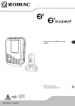
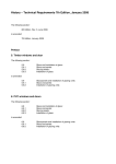
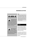
SPA DE USO PRIVADO
SPA FOR PRIVATE USE
SPA POUR UN USAGE PRIVÉ
SPA FÜR PRIVATE NUTZUNG
SPA PER USO PRIVATO
SPA PARA USO PRIVADO
SPA VOOR PRIVE-GEBRUIK
MANUAL DE INSTALACIÓN
INSTALLATION MANUAL
MANUEL D’INSTALLATION
MONTAGENHANDBUCH
MANUALE D’INSTRUZIONI
MANUAL DE INSTALAÇÃO
INSTALLATIEHANDLEIDING
RELEASE 01
01-2011
2
ES
3
EN
19
FR
35
DE
51
IT
67
PT
83
NE
99
CONTENTS
1. General details
20
2. Safety warnings
21
2.1. General
21
2.2. Warnings in installation and assembly work
21
2.3. Warnings in maintenance work
21
3. Installation and assembly
22
3.1. Positioning and location of the Spa
22
3.2. Drainage of the Spa
23
3.3. Electrical connection
24
4. Start-up
31
4.1. Filling the Spa
31
5. Troubleshooting
33
6. Declaration of Conformity
34
IMPORTANT
This instructions manual contains fundamental information on the safety measures
to be adopted when installing and starting-up the spa. It is therefore essential
that both the Fitter and the User read these instructions before assembly and
start-up.
19
1. GENERAL DETAILS
This manual contains all the information needed to fully enjoy your SPA. We recommend that you
take some time to go over the points detailed below.
If you have any question or doubt on the operation or maintenance of this product, please contact
your fitter or local dealer. They are specialists and their professional knowledge will help you to
enjoy this product.
IMPORTANT: The manufacturer reserves the right to change the design or specifications without
prior notice and without entering into any obligation.
ATTENTION - IMPORTANT
•
Before carrying out any work on the Spa, it should be switched off from the
electrical supply (differential in the OFF position, or disconnect the mains
cable).
•
This equipment cannot be connected to a normal plug
•
This equipment requires suitable electrical installation. This should be
performed by a qualified person following the electrical safety standards of
each country.
•
The electrical supply of the Spa should always be protected by a highly
sensitive differential. A 30 mA differential is recommended.
•
Earth connection is essential. The earthing circuit of the building should
always be in perfect condition to guarantee the safety of the Spa user. If you
have any doubts on this, ensure that the earth circuit is checked by a qualified
person. The manufacturer is not responsible for possible damage caused by
unsuitable maintenance of the earth circuit.
•
Do not connect the electrical equipment (differential in the ON position), if the
Spa is empty of water.
•
Use a cable of a section suitable to the power of the Spa and the distance to the
panel.
•
Always observe the instructions included in Safety Warnings chapter of this
manual.
•
Never try to access an electrical component unless you are qualified or are the
Head of Maintenance.
•
Never handle electrical elements with wet feet.
20
2. SAFETY WARNINGS
2.1. GENERAL
•
Avoid contact with electrical voltage.
•
Carefully follow current regulations regarding accident prevention.
•
Any modification on the equipment requires prior authorisation from the manufacturer.
Original spare parts and accessories authorised by the manufacturer guarantee greater safety.
The manufacturer of the equipment is exempt from all liability for damages caused by using
non-authorised spare parts or accessories.
•
During operation, some parts of the equipment are at dangerous electrical voltage levels. Work
on each element or equipment can only be performed once it has been disconnected from the
mains and having disconnected the start-up devices.
•
The user should ensure that assembly and maintenance works are carried out by qualified and
authorised persons, and that they have carefully read the installation and service instructions.
•
Safety in the operation of the machine can only be guaranteed if installation and service
instructions are followed.
•
The limits indicated in the electrical control panel cannot be exceeded under any circumstances.
•
Contact the Technical Service of the manufacturer or the local dealer of the manufacturer in the
event of malfunction or a breakdown.
•
The Spa should be installed following current regulations applicable in each country, particularly
those referring to electrical safety.
•
There is risk of flooding with this equipment, and therefore it should be installed in an area
prepared to collect and drain any water that may overflow (both under and around the spa),
owing to its use or possible leaks in any of the circuits. (See the Guarantee).
•
The equipment should be installed in a place which has been properly prepared and where
all components of the Spa can be easily accessed. The guarantee does not cover work
needed to be carried out to install or replace the product. (See the Guarantee).
2.2. WARNINGS IN INSTALLATION AND ASSEMBLY WORK
•
While connecting the electrical cables to the equipment, ensure that the layout inside the
connection box is correct, check that there are no pieces of cable remaining inside after it is
closed, and that it is properly earthed.
•
Take particular care to ensure that water cannot enter the pumps and live electrical parts.
2.3. WARNINGS IN MAINTENANCE WORK
•
Before carrying out any electrical or mechanical maintenance work, make sure that the
machine is disconnected from the mains, and that the start-up devices are blocked.
•
Do not handle the equipment with wet feet.
21
•
In natural wood panelled Spas, never perform maintenance work if the panels are damp,
because their dimensions might vary due to humidity absorption. If this occurs, it could be
very difficult to assemble the panels. Wood panels must be completely dry before
performing any work on them.
3. INSTALLATION AND ASSEMBLY
Before installing and assembling the Spa, ensure that the packaging of the Spa is in perfect
condition. Contact your distributor immediately if the packaging is damaged.
3.1. POSITIONING AND LOCATION OF THE SPA
Position the Spa horizontally, placing the whole base of the unit on a smooth, flat and level
surface, capable of supporting the weight when used (full of water, plus the weight of the bathers).
The Spa cannot be placed on a curved surface or on blocks.
3.1.1 PORTABLE ADJUSTABLE SPAS
Some spas come with a metal structure to facilitate their installation. This structure has several
points of support. Before filling the spa, these points of support should be adjusted to ensure they
are all in contact with the ground.
Avoid placing the Spa where water could leak into the electrical equipment compartment, and also
protect the unit from direct contact with very damp areas.
The side where the motors are located should be fully accessible. In order to carry out
maintenance tasks, the location of the Spa should enable it to be moved so that all its sides can be
easily accessed.
22
Outdoor installation
If an outdoor location is chosen to place the Spa:
•
Do not expose the Spa to sunlight when it is empty and without a protection cover.
Remember that prolonged exposure to sunlight may damage the surface of the Spa and its
accessories. Acrylic rapidly absorbs heat from the sunrays reaching very high temperatures
which will damage the Spa.
Maximum absorption temperature is 60ºC.
•
It is recommended to place the Spa away from trees, as falling leaves may block the filter.
•
If the Spa is placed inside glass structures, prevent sunrays shining directly on the Spa through
the glass, as the temperature could be excessively hot.
Indoor installation
It is recommended to ensure drainage in the area of the Spa, to prevent water from accumulating
around it and to avoid dangerous access areas for bathers.
Remember that the operation of the Spa causes increased damp and therefore, there must be a
ventilation system to prevent damp from accumulating which could cause damage in the room
where the Spa is located.
The use of a cover reduces heat loss and damp in the room.
The Spa should not be left empty and uncovered at room temperatures over 20ºC or below 4ºC.
3.2. DRAINAGE OF THE SPA
The Spa has a manual emptying system by gravity, through a drainage valve of 3/4”.
The drainage valve should always be closed. It should only be open when the Spa is emptied.
If necessary, a drainage system can be installed to connect the Spa to the general drains of the
house. In this case, the steps 5 and 6 are not necessary.
23
Operation of the valve is:
3.3. ELECTRICAL CONNECTION
ATTENTION – VERY IMPORTANT
•
This equipment cannot be connected to a normal plug.
•
This equipment requires suitable electrical installation. This should be done by
a specialised fitter following local electrical safety regulations of each country.
•
The electrical input of the Spa should always be protected by a highly sensitive
differential. A 30 mA differential is recommended.
•
Earthing connection is essential.
•
Use a suitable section cable bearing in mind the power of the Spa and distance
to the control panel.
•
Always follow instructions given in the Safety Warnings chapter of this manual
24
ATTENTION - RISK OF ELECTRIC DISCHARGE
•
The electrical supply should be switched off (differential in the OFF position or
disconnect the cable from the mains) before carrying out any work.
•
Never try to access an electrical component unless you are qualified or are the
Head of Maintenance.
•
Always use suitable personal protection equipment and tools when handling
electrical equipment.
•
Never access electrical elements if you are wet, particularly if you have wet
feet.
•
Do not connect the electrical equipment (differential in the ON position), if the
Spa is empty of water.
Follow these steps to connect the Spa:
3.3.1 Locate the electrical panel of the Spa
Locate the electrical control panel; to do this, open the side panel to access the electrical
components. The door is anchored by screws.
The control cabinet is the box that is in front of the electrical heater element. To open it the four
screws on the front cover must be unscrewed.
25
3.3.2 Installation of the differential
• The electrical installation should incorporate a high-sensitive 2-pole differential in the
general mains input panel (the differential is not supplied with the Spa).
•
ATTENTION – It is essential that the owner of the Spa tests the differential switch at least
once a month, to check its good working order.
A differential
must be installed
Check that the differential is in the OFF position. Do not place the differential in the ON position
until the Spa is filled with water.
OFF
(GREEN)
ON
(RED)
3.3.3 Connect the electrical control panel of the Spa to the differential switch.
Before carrying out any work on the Spa, make sure it is disconnected from the mains (differential
switch in the OFF position, or disconnect the cable from the mains).
Use a suitable cable from the differential switch to the electric cabinet of the Spa, depending on the
location and applicable law. The cable section will vary depending on the Spa model and the
distance of the installation.
The required kW are indicated in the appendix Technical Specifications of the Spa. The maximum
power must be considered, depending on the “High Amp” or “Low Amp” configuration.
26
High Amp/Low Amp setting
Power consumption can vary considerably depending on the spa setting selected. Therefore, the
type of installation chosen will determine the amount of electricity consumed.
LOW AMP:
This setting disconnects the electric heater when any of the massage pumps are working, which
reduces electricity consumption. This is the manufacturer’s default configuration.
HIGH AMP:
This setting makes it possible for all spa components to work at the same time. This type of
installation consumes more power.
Changing from a low amp to a high amp setting is achieved thanks to the switches on the
switchboard.
IMPORTANT:
The Electric Specification Sheet attached to the manual indicates both the “Low Amp” and the
“High Amp” power. To determine the cable section of the electrical installation, see the values
indicated in this sheet and the following table:
Table of required sections, distance and power
kW required
2.1
2.5
2.8
3.2
3.5
4.4
5.3
6.2
7.0
Distance
Nominal section of the cable in mm
7.9
8.8
2
6 – 11
m
2.5
2.5
2.5
2.5
4
4
6
10
10
10
10
11 - 15
m
2.5
2.5
4
4
4
6
6
10
10
10
10
15 – 20
m
4
4
4
6
6
6
10
10
10
16
16
For longer distances, increase the cable section accordingly.
27
Some configurations may require installing 1 32A line, 2 16A lines or even one three-phase line (3
x 16A) to cover the power required by the Spa.
The different configuration options of the electrical control panel are explained further on in this
Installation Manual.
Remember that the installation and any changes in the electric configuration must be carried out
by qualified personnel, following the current regulations in each country.
The manufacturer shall not be responsible for any damage caused by an improper installation or an
installation performed by non-qualified personnel.
ATTENTION
Pay attention to the position of the maximum consumption switch.
The Spa will not operate properly if a cable not corresponding to the distance and
power of the Spa is used, and the electrical circuits may overheat which may cause
an electrical accident. Always use cable with the suitable section of maximum
consumption. In the event of doubt between two values, always use the cable with
the greater section.
To connect the supply to the electrical panel of the Spa, locate the packing gland positioned at one
end of the electrical panel.
Make sure that there is no electric current in the connection cable (differential switch in the OFF
position).
Take the cable to the Spa electrical panel.
Open the cover of the electrical cabinet, insert the feed cable through the free side .
Attention: the indicated blue cable is neutral, and the brown cable indicates the line or phase.
Fasten the terminals as indicated in the following diagrams and the type of electrical supply.
28
Single line 1x16A or 1x32A
Double line 2x16A
Three-phase line
29
ATTENTION
Correct earthing is essential
The earthing circuit of the building should always be in perfect condition to
guarantee the safety of Spa users. If you have any doubts on this, ensure that
the earthing circuit is checked by a duly qualified person. The manufacturer will
not be held responsible for possible damage caused by incorrect maintenance of
the earthing circuit.
Fasten the earth cable (yellow and green) to the terminal on the outside of the control cabinet
as shown in the following diagram:
EARTH
ATTENTION
Do not connect the electricity (differential in the ON position) until the Spa is
filled with water
30
4. START-UP
ATTENTION
Before start-up, read the following points carefully.
4.1. FILLING THE SPA
The Spa does not have a specific filling system. It is recommended to use a manual filling system
with a garden hose or similar.
Proceed as follows:
• Before starting filling the Spa, locate the drain valve (see “Locating the drain valve”) and
ensure that it is in the CLOSED position.
• Fill the Spa through the top, with clean water, to the level indicated on the label placed in the
skimmer area (water should cover the filter by at least 3 cm.).
4.1.1 FILLING PRIVATE OVERFLOW SPAS
It is recommended to fill the spa manually using a garden hose or a similar system.
Proceed as follows:
Before filling the spa, find the drainage valves and ensure they are all closed, except for the safety
outlet, which should always be open.
Fill the spa from above using clean water until the spa starts to overflow.
Fill the three pumps with at least 15 cm of water so that the filter pump does not take in air when
working normally.
Connect the water supply to one of the tanks’ inlets.
Before opening the filter lid ensure that the 3 valves that regulate the filtration
circuit are closed. If they are open the spa would be emptied through the filter
31
WATER SUPPLY
SAFETY OUTLET
The spa has a filling system that works using a ball cock. The outlet of the ball cock must be
connected to the mains supply at a constant water pressure.
When the spa loses water as a result of evaporation, the system automatically fills the tanks.
The compensation tanks have a safety outlet for removing water.
WARNING
THE COMPENSATION TANKS OF PRIVATE OVERFLOW SPAS HAVE A LIMITED
CAPACITY.
THEY CAN HOLD 280 LITRES OF WATER, EQUIVALENT TO 4 PARTIALLY SUBMERGED
PEOPLE.
USERS SHOULD ENTER THE SPA ONE BY ONE AND SLOWLY TO ENABLE THE TANKS TO
ABSORB THE DISPLACED WATER AND PREVENT WATER FROM FLOWING OUT OF THE
SPA.
WARNING
During the filling process, water should be prevented from entering electrical parts.
If seawater is used in the Spa, the circuit components will quickly deteriorate.
Do not fill the Spa with hot water, as this could trigger off the safety thermostat and
damage equipment and connections.
Once the Spa has been filled with water, connect the electrical equipment by placing the
differential switch in the On position (See Electrical Connection).
Do not use the Spa without first carefully reading all the information detailed in the following
points:
32
•
•
•
•
Adjust water pH between 7.2 and 7.4 (see Water maintenance).
Add all required chemical products recommended in Water maintenance (Maintenance Manual)
Select the required temperature (see Control Keyboard of the Spa). Remember that if the
water is cold, it may take 24 hours to reach a temperature of 38ºC.
Before using the Spa, check the pH values once again in case they have changed with the
treatments indicated above.
5. TROUBLESHOOTING
PROBLEMS
REASONS
SOLUTIONS
Insufficient flow of filtered
water.
Filter is blocked by dirt.
Wash the filter.
The massage pump of the Jets
does not work.
The cable of the digital control
panel is disconnected from the
board.
Connect the cable to the board.
Spa does not work.
The massage pump of the air
Blower does not work.
No electrical supply
Check that the pump is
connected to the electric control
panel.
Differential is disconnected
Connect the differential.
The cable of the digital control
panel is disconnected from the
board.
Connect the cable to the board.
No electrical supply
Check that the pump is
connected to the electric control
panel.
The pump has disconnected
owing to overheating.
Let it cool for about 3 hours
and then start-up the pump
again.
Water leaks out through the
Venturi
Jets are closed.
Open the jet.
Jets are not properly installed.
The outer trim of the jet turns a
quarter to open and close the
water flow. If this trim makes a
complete turn, it is not properly
installed, and the jet will have
to be removed and then placed
correctly.
Remove the jet. Pull the outer
trim about 2 cm. Unscrew the
jet turning anti-clockwise. Once
it has been dismantled, replace
the jet, by screwing in a
clockwise direction. Press the
outer trim back into place.
Limited airflow in the Jets.
Venturis are closed.
Open the Venturis.
Reduced airflow.
Starter brushes of the motor are Change the pump.
worn.
The water does not reach the
required temperature.
Probe is damaged.
Replace the temperature probe.
Check programmed temperature Programme the temperature
Note: In the section Diagnosis message of the control panel (User Manual), the diagnosis
messages to solve possible breakdowns are indicated.
33
34
115