1
vWire User’s Manual
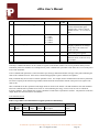
vWire DC Specifications T=25 degrees C
Parameter
Description
Minimum
Typical
9
Maximum
Units
30
Volts
Note
s
Vs
Min-Max supply voltage range
Isrx
Rx supply current 9/12/24V
30/25/15
45/37/22
mA
Istx
Tx supply current 9/12/24V
100/80/45
150/120/60
mA
Vin 1
Analog voltage input mode range 1
0
2.5
Volts
1
Vin 2
Analog voltage input mode range 2
0
5.0
Volts
1
Vin 3
Analog voltage input mode range 3
0
20.0
Volts
1
Zvin
Analog voltage input Z
AI
Analog current input mode
Zai
Analog current input mode Z
DacV
DAC voltage output range
0
VRelay
Relay contact voltage range
IRelay
100K
Ohms
mA
1,2
Ohms
2,4
5
Volts
1
0
60
Volts
AC/DC
Output current range
0
0.5
Ampere
| DICOM – Din |
Digital input common-voltage
range
0
30
Volts
Vt
Din channel threshold
1.4
4
Volts
Din
Din channel OFF/ON levels
DICOM +/- Vtmin
> (DICOM + Vtmax)
or
Volts
3
0
20
125
3
< (DICOM – Vtmax)
Idin
Digital input current
0
(|DICOM – Din| - 2) /
3.4
mA
3
Idin24
Digital input current |DICOM - Din|
= 24V
0
6.5
mA
3
Idin12
Digital input current |DICOM - Din|
= 12V
0
3
mA
3
Idin5
Digital input current |DICOM -Din|
= 5V
0
0.9
mA
3
Notes:
1.
2.
3.
4.
Basic measurement resolution is 10 bits. Vref is 2.5V. Input range is set with switch S1.
Limit input current to <= 20mA to prevent excess power dissipation in input termination resistor.
Limit absolute voltage difference between DICOM and Din to +/-30V
Vin to ADC will be Input current x 125 ohms. For I = 20mA and ADC channel gain set to 0 – 2.5V this gives full scale 10 bit value (1023).
iP Solutions Corporation • 41784 Higgins Way • Fremont, CA 94539 • Phone: (510) 651-6403
Rev 1.7a August 18, 2009
Page 2