1
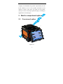
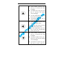
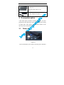
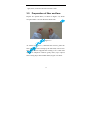
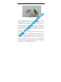
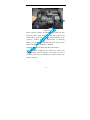
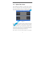
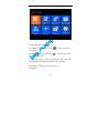
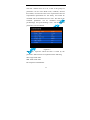
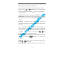
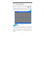
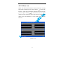
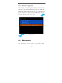
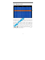
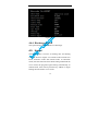
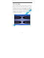
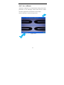
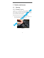
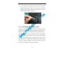
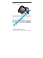
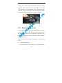
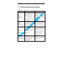
User Manual MW5200/M
FIBER FUSION SPLICER
MW5200/M
OPERATION MANUAL
1
User Manual MW5200/M
Contents
1.
Notice before using ......................................................... 1
1.1.
Safety instruction ........................................................ 1
1.2.
Note ............................................................................. 2
1.3.
Legal statement ........................................................... 3
2.
Start to comprehend splicer .......................................... 4
2.1.
Overview of splicer ..................................................... 4
2.2.
Key .............................................................................. 5
2.3.
Technical parameters ................................................... 9
2.4.
Tools configuration .................................................... 11
3.
A complete splice .......................................................... 12
3.1.
Power on ................................................................... 12
3.2.
Preparation of fiber end face ..................................... 13
3.3.
Fiber clamping .......................................................... 15
3.4.
Optical fiber fusion ................................................... 17
3.5.
Heat-shrinkable ......................................................... 18
3.6.
Cooling ...................................................................... 19
4.
Menu instruction .......................................................... 19
4.1.
Parameter setting menu ............................................. 21
4.2.
Setup ......................................................................... 24
4.3.
Function .................................................................... 29
2
User Manual MW5200/M
4.4.
Maintenance .............................................................. 33
4.5.
Heater ........................................................................ 38
4.6.
Electrodes .................................................................. 40
4.7.
Status ......................................................................... 43
4.8.
Information................................................................ 44
5.
Routine maintenance ................................................... 45
5.1.
Cleaning .................................................................... 45
5.2.
Replacing electrode ................................................... 48
5.3.
Electrode aging ......................................................... 50
5.4.
Software upgrade ...................................................... 51
6.
Common fault and solution ......................................... 52
7.
Appendix A ................................................................... 54
3
1. Notice before using
1.1. Safety instruction
Please read the following information before first using.
1.
Use the specified battery and adaptor, otherwise it may
cause an explosion or permanent damage of the
machine.
2.
Don't use the machine in high temperature, flammable
and explosive environment (such as a gas station
nearby).
3.
Don't attempt to disassemble the machine and its
accessories, only authorized agencies can repair the
machine.
4.
Please don't contact electrode rods in working
condition, or it may cause personal injury.
5.
When there are liquid, foreign matter into the machine,
or a smoke, odor, noise, etc., or the machine is strong
impact, please immediately shut down the machine,
and pull out the AC power.
1
1.2. Note
When using the machine, improper operation may result
in machine damage or human health. It is suggested to
use the machine in the following way.
1. This type of machine is only used for splicing quartz
glass fiber, not in place of any other matter.
2. Don't use or storage of the machine in high temperature
or humidity environment (otherwise it may damage the
equipment or cause machine performance degradation).
3. While using the machine in the dust environment,
please avoid the dust as far as possible.
4. When moving the machine from the low temperature
environment to the high temperature environment,
there should be any heating process to eliminate
condensation.
5. Please use high-purity anhydrous alcohol (purity>99%)
to clean magnifying lens, reflector and Fiber V-groove
surface.
6. The splicing machine must be handled gently to avoid
strong vibration and impact, use with carrying case for
transportation and storage.
7. The machine maintenance once a year.
2
1.3. Legal statement
Without written consent of our company, any unit or
individual will not be allowed to extract or copy part of the
contents of this manual, or transmitted in any form.
Products described in this manual, including our company
software, unless approved by the related oblige, otherwise
no one can be in any form for the software to copy,
distribute, modify, excerpts, decompiling, disassembling,
decryption, reverse engineering, lease, transfer, sublicense
and other ACTS of infringing the software copyright.
Attention: The manual describes some features and
functions of the product and its accessories, related to the
production batch, therefore, description in this manual may
not exactly match the product you purchased, as well as its
accessories. Our Company reserves the right to modify any
information in this manual at any time, without any prior
notice and does not undertake any responsibility.
Limitation of liability: Within the scope of applicable law,
our company, in any case, don’t compensate for any special,
incidental, indirect, secondary damage due to using this
manual or the product, and also don’t compensate for any
loss of profits, data, goodwill or anticipated savings.
Within the scope of applicable law, in any case, our
3
company will undertake the greatest responsibility for the
losses suffered in use of the product described in this
manual in limit of the price you paid for the product.
(Except in cases involving of personal injury according to
applicable law for damages)
2. Start to comprehend splicer
2.1. Overview of splicer
Figure 2.1
4
2.2. Key
2.2.1. Key appearance
Figure2.2
Table 2.1
1 Power
2 Enter
3 Menu / Exit
4 Up
5 Left
6 Down
7 Right
8 Heat
9 Arc
10 Reset
11 Switch video
12 Auto splice
5
2.2.2. Key function
Table 2.2
z
While Power On, press this key
to shut down.
z
While Power OFF, press this
key to Power On.
z
Under standby interface, press
this key to discharge weak arc.
z
In menu, press this key to enter
the next submenu.
z
If permitted, press this key to
run.
z
If permitted, press this key to
switch between the left and
right sides of CMOS Sensor,
Motors and so on.
z
Under standby interface, press
this key to enter main menu.
z
Under the main menu interface,
press this key to return the
upper menu.
6
z
Under standby interface, press
this key to increase the LCD
backlight.
z
In CMOS sensor step, press this
key to increase the CMOS
sensor backlight.
z
In motor adjustment, press this
key to drive up the fiber.
z
If permitted, press this key to
move up the cursor.
z
Under standby interface, press
this key to gap the fiber.
z
Under the main menu, press this
key to select the left icon.
z
In motor adjustment, press this
key to drive the corresponding
motor move to left.
z
Under standby interface, press
this key to decrease the LCD
backlight.
z
In setup of CMOS sensor, press
this key to decrease the CMOS
sensor backlight.
z
In function of motor test, press
this key to move down the
7
corresponding motor.
z
If permitted, press this key to
move down the cursor.
z
Under standby interface, press
this key to align the fiber.
z
Under the main menu, press this
key to select the right icon.
z
In motor adjustment, press this
key to drive the corresponding
motor move to right.
z
Under standby interface, press
this key to fuse.
z
In Power On state, press this
key to reset motor position.
z
Under standby interface, press
this key to switch video mode.
z
Under standby interface, press
this key to run auto splice.
8
2.3. Technical parameters
Table 2.3
Fitted fiber
SM,MM,DS,NZDS
Cladding diameter 80 -150um
Coating diameter 100 - 1000um
Typical loss
SM:<=0.02dB; MM:<=0.01dB;
DS:<=0.04dB; NZDS:<= 0.04dB
Echo loss
Cutting length
> 60dB
10~16mm(Coating layer Diameter:<
250µm)
Program
40 groups
Operation mode
Auto mode and Manual mode
Auto to heat
Supported
Splice time
7 seconds
Heating time
30 seconds(heat-shrinking tube width is
40mm or 60mm)
Magnification
150 times/double show,300 times/single
9
Observation mode
High sensitivity CMOS sensor, Color LCD
of 5.6 inch with pixels 640x480
Fusion Records
Support to store 4000 groups of Fusion
Records
Estimate loss
Supported
Tension
Supported,2N
Operation
GUI
Interface
Battery capacity
Power supply
10.8Ah;Typical 220 times fusion; Show
remaining real-time
Adapter : AC100-240V(50/60HZ);
Output : DC11~13.5V
Electrodes times
4000 times
Interface
12V DC power input,USB2.0
Operation
Altitude:0~5000m;Humidity:0~95%;
Enviroment
Temp:-10℃~+50℃;Air speed:<=15m/s
Volume/weight
160mm(L)×150mm(W)×145mm(H)
/2.8kg(Battery Included)
10
2.4. Tools configuration
Table 2.4
Carrying Case:
¾ Keep the splicer away from the
bumping and compact
¾ Working platform
Fiber Cleaver:
¾ Cutting fiber
¾ Preparation of the fiber end face
Spare electrodes:
¾ Replace the aging electrodes
Strip clamp:
¾ Stripping the fiber coating
Alcohol pump bottle:
¾ Used to hold alcohol
11
Cooling tray:
hold heat shrink tube to cool
AC-DC Adapter for splicer
3. A complete splice
A full fiber splice procedure including: the fiber end face
preparation, fiber splicing, tension test, heating and cooling
of shrink tube. This chapter will introduce details of the
specific process of the fiber splice.
3.1. Power on
Figure 3.1
Press and hold the power button until the power indicator
12
light, then, LCD also enter the self-test screen.
3.2. Preparation of fiber end face
Prepare two optical fibers, as shown in Figure 3.2, which
an optical fiber is set into the heat shrink tube.
Figure 3.2
As shown in Figure 3.3, clenched fiber cleaver, place the
fiber into the tooth of clamp by the left hand, reserve bare
fiber 30 to 40 mm stripped fiber coating. Use a cotton ball
dipped in anhydrous alcohol (purity>99%) wipe optical
fiber coating layer that residual debris, Figure 3.4 shows.
13
Figure 3.3
Put the cleaned fiber into the cutter positioning groove, the
edge alignment of the fiber coating cutter ruler “13” scale
outside (the scale is greater than 13, shown in Figure 3.4).
Close small platen, requiring that the bare fiber straight on
the left and right rubber on the chopping block. Together
close the large plate, and push the cutter blade slider to the
other end to cut off the fiber.
After Cutting, open the large platen to take away cutting
broken fiber into the waste fiber storage box. (Broken fiber
has a great harm to human health, so, please be sure to
collect and chop broken fiber). Open the small platen, and
carefully take out the cut end face fiber. Don’t make the
fiber cross section touching any other objects, in order to
avoid damage or contamination end face.
14
Figure 3.4
3.3. Fiber clamping
Open the windproof cover and the two side fiber platens,
then, put the prepared fiber into V-groove through the
locating slot. Make sure that the fiber end face should be
located between V-groove edge and two electrodes.
Shown in Figure 3.5
15
Figure 3.5
Please operate carefully and don’t let the fiber end face
touch any other object. Then close the large platen to fix
optical fiber, which should be placed horizontally in the
V-groove, without upturned phenomenon. If clamping
failed, you can lift fiber carefully and repeat the operation
above until the fiber clamping is qualified.
Similarly, prepare and clamp the other optical fiber.
Then, close the windproof and continue to observe the
amplified fiber from the display. If the fiber end face is
obviously uneven, tilt or damaged, you need to remove the
fiber to cut again.
16
3.4. Optical fiber fusion
After clamping, the machine is in ready state, as shown
below. If in "Automatic" splice mode, auto splice begins as
soon as the windproof closed. If in "Manual" splice mode,
user must press the "SET" button to run the splice routine.
Figure 3.6
First, select fusion parameter group according to the optical
fiber type. Press “MENU” to enter the main menu, and then
select the “parameters” icon and press the “confirm” key to
enter the menu. We need to select fusion parameter group
matched with splice fiber type. It is suggested to choose the
automatic splice parameter group for new users.
Press "SET" to start the splice procedure. The machine
17
drives the motor, which will promote both sides of fibers to
the middle of the screen, judging the fiber end face whether
meet the requirements. If qualified, turn to the next process,
otherwise show a tip of bad end face and stop.
After judgment, alignment motor will adjust fiber position
to make both sides of fibers align in three-dimensional. At
last, the electrode discharge arc to fuse fiber. When fusion
completed, the machine will give the loss estimates, and
have a tension test if needed.
3.5. Heat-shrinkable
Optical fiber fusion point is really fragile and easily broken,
so, you need protection by using heat shrinkable. Open the
windproof cover, large platen and heater cover. Gently
remove fiber, and don’t bend fiber greatly to avoid the
fusion point broken.
Move heat shrinkable tubing to the fusion point, which
must be in the middle. Then, place heat shrinkable tubing in
the middle of the heating furnace. The heater begins
heating as soon as heating furnace closed. About 30
seconds later, heating shrinking has completed. The figure
below is the heat shrink tubing before thermal shrinkage
and after thermal shrinkage.
18
Figure 3.7
3.6. Cooling
The heat shrinkable tubing after heating is in high
temperature, and need cooling. Hang the cooling tray on
the carrying handle. So, after heating, pull out the fiber
from the heating furnace to the cooling tray by hands.
About 1 minute later, it cools to the ordinary temperature.
4. Menu instruction
The machine adopts METRO-style menu, whose interface
is simple, beautiful and convenience for operation. The
operation interface has 8 icons, and each icon corresponds
to different functional menu.
19
Figure 4.1
For the main menu interface:
In standby state, press the key
main menu.
to enter interface of
In the main menu, press the key
to exit the main menu
to standby interface.
In the main menu, press the direction keys, and the
corresponding direction on the next icon is selected.
Press the key
to enter the submenu.
In submenu:
20
Press the key
or
to select the up down cursor.
Press the key
or
Press the key
to enter the next submenu.
Press the key
to enter the upper menu.
to modify the current data.
4.1. Parameter setting menu
Figure 4.2
"Parameters" menu is used to select and set the fiber
splicing parameters. Menu forms by different splicing
parameters submenu, as shown in Figure 4.2. Each
sub-menu is a group of splicing parameters, and the menu
is composed by the part of the number, file name, pattern
21
and state. Number from 0 to 39, a total of 40 groups of
parameters can be used. Mode Auto, Calibrate, Normal
three kinds, of which the Auto class of parameters derived
experimental optimization for the factory and cannot be
modified and recommended for new users. The data of the
Calibrate
parameters
can
be
modified
except
the
pre-discharge and post-discharge time. All the Normal
parameters can be modified.
Figure 4.3
The “type” represent which the fiber is fused by the
parameter. Abbreviations are explained in the following.
SM: Single mode fiber
MM: Multi mode fiber
DS: Dispersion shifted fiber
22
NZDS: Non-zero dispersion-shifted fiber
The state ON/OFF says the group is currently used or not.
Press the key
or
to change the current splicing
parameter group. Press the key
to enter the para group,
as shown above.
The parameter consists of the following parameters:
Prefuse time Prefuse time in total fusion process, a short
time about 10ms. It is not recommended for the new user to
modify.
Fuse time
Fuse time in total fusion process, a long time
more than 1 second. It is not recommended for the new user
to modify.
Arc
Discharge current means that the discharge arc
current intensity. The high value of the current corresponds
to a greater arc, resulting in a higher temperature. The fiber
is ablated more seriously. Press the key
increase or decrease the parameter value.
or
to
Pushing overlap The pushing forward distance in fusion
process. Press the key
or
to add or sub the value of
overlap.
Gapping
The distance of fiber gap before fusing. Press
the key
or
to change it.
Max end face The angle between the fiber end and vertical
23
direction is the end face. In the process of judging the fiber
end face, the fiber end face should not more than the Max
end face.
State
It shows the using state of the current viewing
parameter group. You can press the key
change the parameter.
or
to
4.2. Setup
The “setup” menu is used to set the data including the
operation mode, language, camera brightness, tension and
auto shutdown, as shown below.
Figure 4.4
24
4.2.1. Operation mode
The operation mode is the method of machine fusion,
consists of: automatic or manual mode.
This parameter, automatically, turn off the windshield in the
standby inter face, the splicing machine will begin running
splice fiber optic procedures. Manual mode requires user to
press the "SET" button, and the machine will begin splicing
optical fiber. Select the menu button, and press the key
,
the parameter values will switch between "automatic" and
"manual".
Suspend 1
When fiber splicing, fiber advancing to meet
the gap conditions, the program pauses, waiting for the
further operation of the user. For continue to splicing, press
"SET" button. To interrupt splicing, press the "RESET"
button.
Suspend 2
Fiber suspend the running at the end of the
subsequent process of aligning.
Reset time
After a fiber splicing, in order to prepare for
the next splice, propulsion motors need to be reset to the
reference position. Fiber splicing completed, open the
windscreen, over a period of time to wait for propulsion
motors begin to reset. The waiting is the time that
automatically reset. The menu selected, press the key
25
or
to change the parameter values.
Figure 4.5
26
4.2.2. Language
Language shows the display language current software
used. There are two languages available:
¾
Chinese
The software interface displays Chinese.
¾
English
The software interface displays English.
Figure 4.6
27
4.2.3. Camera brightness
Press the key
to enter the interface of camera
brightness, as shown below. Press the key
or
to
modify the gain of CMOS camera resulting in the change
of camera brightness. Press the key
CMOS camera sensor between X and Y.
to switch the
Figure 4.7
4.2.4. Tension
Open the option, splice completed, the machine would
impose 2 Newton’s pulling on the fiber to test the quality of
splicing. If the fiber broken, it means the fusion failure.
Press the key
and OFF.
to switch the tension state between ON
28
4.2.5. Auto shutdown
When the option turned on, the machine will shut down
automatically if no operation within ten minutes.
4.3. Function
The function menu lists the splicing machine with some
features, such as time and date, motor test, export splicing
records, program upgrade, ect. as shown in Figure 4.8.
Figure 4.8
29
4.3.1. Date and time
Press the key
to enter the interface of Date and Time as
shown in figure 4.9. Press the key
or
to move the
selection cursor, and then press the key
modify the selection value.
Figure 4.9
30
or
to
4.3.2. Motor test
Motor test imitates the distance of the push motor moving
forward in the fusion process. Press the key
to enter the
interface. After the prepared fiber clamped into the machine,
you must press the key
to run the test. The test results
will be given at the end of the test, as shown in Figure 4.10,
which shows the distance of each push motor moving
forward.
Figure 4.10
31
4.3.3. Export records
The option is used to export the fusion records memories in
the machine. After the U disk inserted into the USB port,
choose this option and press the key
to confirm fusion
records export. As Figure 4.11 shown, program begins to
test USB port and then find the records. If there’s no record,
program will prompt error.
Figure 4.11
32
4.3.4. Software upgrade
This function is used to upgrade software in the machine.
After the U disk with upgrade file inserted into USB port,
choose this option and press the key
to upgrade. As
shown in Figure 4.12, program begins upgrading. Attention
that after upgraded, users need to boot.
Figure 4.12
4.4. Maintenance
The Maintenance menu consists of Electrodes Aging,
33
Motor Checking, Fusion Records, Arc Numbers, etc, as
shown in Figure 4.13.
Figure 4.13
4.4.1. Electrodes aging
New electrode discharge instability and the need for the
discharge of a certain number of times to stabilize the arc
which called electrode aging.
34
When electrode replaced, enter this menu and then press
the key
to start aging the electrode, as shown in Figure
4.14. Don’t open windproof cover in aging process.
Figure 4.14
4.4.2. Motor checking
Motor checking is used to check the motor performance
and change the motor position. Total of 4 motors are
available for operation.
35
Figure 4.15
Press the key
to enter the video interface. Press the key
to switch the left and right motors. The align motor will
move up or down by pressing the key
or
motor will drive left or right by pressing the key
36
. The push
or
.
4.4.3. Fusion records
Figure 4.16
This option stores working parameters, fiber end face, the
environment and date in each splicing. The machine can
store 4000 groups of fusion records. The key
can be
pressed to enter the page of fusion record, and the page
displays ten groups of fusion records, sequence from top to
bottom by the latest fusion time as shown above. Press the
key
or
to the contiguous page. Press the key
enter the page of fusion records.
37
to
Figure 4.17
4.4.4. Discharge records
This option shows the total number of discharge.
4.5. Heater
The Heater menu is used to set heating time and heating
mode, as shown in Figure 4.18. Heater mode includes two
kinds, automatic mode and manual mode. In automatic
mode, after the heater the heat shrink tubing loaded and the
cover closed, the program begins heating automatically. In
manual mode, users need to press the key “HEAT” to begin
heating after the heater cover closed.
38
Heat time needs to set by users according to specific heat
shrinkable. Select this option “Heat Time”, and press the
key
or
to change the time. Select the option “Auto
Heat”, and press the key
or
to change the mode.
Figure 4.18
39
4.6. Electrodes
Electrodes menu is used to view and calibrate the arc
degree. The electrodes discharge arc without motor pushing
forward when the fiber is ready for fusion. The fiber is
burned into the shape of arc, and the shortest distance of the
shape of arc reflects the electrodes arc degree. In general,
the shortest distance 9mm to 12mm (Standard distance)
will get loss less than 0.02db.
Figure 4.19
40
4.6.1. Arc adjust
Select this option into the video interface, as shown in
Figure 4.20. Cut and clamp fiber according to splice
procedure, and then press the key
. The calibration
program starts to run and test results are given. According
to the test results, manually set the splicing parameters of
discharge current, and repeat the above steps until the test
results meet the requirements.
Figure 4.20
41
4.6.2. Arc calibrate
Automatic calibration can automatically change the fusion
parameters in the discharge current until the test results
meet the requirements on the basis of test results.
The test interface is shown in Figure 4.21.
Figure 4.21
42
4.7. Status
Status menu gives the atmospheric pressure, the internal
temperature, the ambient temperature and the remaining
power, as shown in Figure 4.22.
Figure 4.22
43
4.8. Information
In Information menu, users can inquiry the serial number of
the machine and software version information, as shown in
Figure 4.23 below.
Figure 4.23
44
5. Routine maintenance
5.1. Cleaning
5.1.1. Cleaning V groove
V-groove is a V slot on the ceramic substrate of narrow
width, easily to accumulate dust which will make the fiber
move instability and cause a bad fusion, therefore, the V
groove should be cleaned regularly.
The following is the way of cleaning the V groove:
1. Place the fiber with good enface into the V groove to
remove the pollution, shown in figure 5.1.
Figure 5.1
45
2. Use a cotton swab soaked with alcohol to clean the
surface and bottom of the V groove. At last, the alcohol
should be the natural air-dry or wiped dry by the dry
cotton swab. Shown in figure 5.2.
Figure 5.2
5.1.2. Cleaning fiber presser foot
The dust accumulated on the fiber press foot will cause the
pressure instability and affect the quality of fusion. So, it
should be wiped off from the fiber pressure foot regularly.
Open the windproof cover, and then use the cotton dipped
in alcohol to clean the surface of the presser foot. When
cleaning, don’t repeat back and forth with cotton, but to
wipe the foot in one direction. Besides, users need to spin
the cotton swabs, keeping the unused cotton facing the
presser foot, waiting for the alcohol volatile.
46
5.1.3. Cleaning reflector
Figure 5.3
When the reflector accumulated with dust, the fiber
imaging through the reflector will fuzzy and in incorrect
position as a result of bad fusion loss, so the dust should be
wiped off from the reflector regularly.
When cleaning, with reference of the below graphic, from
the center to the edge of the reflector, user should rotate the
cotton ball dipped in alcohol to clear repeatedly until the
reflector is of neat and tidy.
5.1.4. Cleaning objective lens
Microscope is the core component of the machine optical
47
system. So its surface must be kept clean, and users should
regularly clean. The microscope is cleaned by the swab
which dipped in a little alcohol, with a spiral movement
from the center to the edge of the lens and the rotation
around the swab until to spin out the edge of the lens.
Figure 5.4
5.2. Replacing electrode
Arc produces by high temperature, melting the fiber, which
will produce silicon oxide vapour and some deposited on
the electrodes, causing the arc instability. Therefore, users
are recommended to replace electrodes when discharge
reached 2500 times.
Please replace the electrodes according to the following
steps:
1.
Shut down the power.
2.
Loosen setscrews of electrodes cover and remove the
48
electrodes cover, as shown in Figure 5.5
3.
Take out the electrode from the electrode holder.
(Electrode is fixed on the electrode holder, figure 5.6).
Figure 5.5
Figure 5.6
49
4.
With tissue paper dipped in alcohol to clean the new
electrodes, then, install the electrodes into the original
electrodes seat position.
5.
Close the electrodes cover and tighten the screws.
6.
Close the windproof cover and power on the machine.
7.
Take an electrode aging.
8.
Run 3 times fiber fusion if current fusion parameter is
Auto mode otherwise run Arc Test or Arc Calibrate if
current fusion parameter is normal or calibrate.
Note: The replacement of the electrodes should be gentle,
so as not to damage the machine or stabbed himself.
5.3. Electrode aging
The electrodes arc begins unstability when the external
environment such as the temperature and pressure changed
greatly especially moving the machine from low altitude to
high altitude. When happened, users should take an
electrode aging to stabilize the electrodes arc. The machine
runs 5 times of huge electrodes arc when the user selects
the electrodes aging and executes it.
Note: Please according prompts to operate, do not open the
cover while electrodes aging.
50
5.4. Software upgrade
The user should insert the USB disk with upgrade file into
USB interface before software upgrade. When the software
upgrade menu is selected and pressed, the machine will
automatically complete the upgrading. After upgrading, the
user should restart the machine.
51
6. Common fault and solution
Table 6.1
Phenomenon
Tip of
“Please
check fiber!”
Tip of
“Please
reload fiber”
Reason
1The fiber is broken.
2 No fiber is loaded.
3 The fiber is far
away from the
Electrodes more
than 2mm
Handle
Making the fiber
image into the
screen after loading
the fiber.
The fiber is not
completely loaded
into the V groove.
Press the Reset key
and reload the fiber
in correct position.
Tip of
“Fusion
failed”
Fusion loss is very
big or Fusion
broken.
Clean the V groove
and fiber press foot;
Check the fusion
parameter and the
motor overlap to
modify.
Electrodes do
not discharge
The electrodes are of
dirty or damaged; Or
the high-voltage
board is fault.
Clean or replace the
electrodes.
52
Tip of
“Please
check L(R)
end face”
The end face of fiber
is bad, or the fiber is
polluted, or the
image is unclear.
Recut fiber or clean
the V groove, or
increase the max
endface value of
fusion para.
Tip of
“Resetting
push motors”
The motor exceeds
the range of
operation reset to the
original
Position.
Reload the fiber in
correct position
when resetting
completed.
Tip of
“Please close
cover”
The cover is opened.
Operate when cover
closed.
Tip of
“X(Y) Image
Light Error”
Display lamp does
not light or some
other reasons.
Chech the
mirror ,lens or the
image light
Tip of
The fiber is not
“(L,R)Fiber
completely loaded
Reload fiber or recut
On
into the V groove or fiber.
Error
fiber is dirty.
position!”
Tip of
The gap of fiber is
Take a gap process
“Please Gap
unfittable.
first.
Again!”
Note: If the above-mentioned problems still exist after
handling, please contact technical support.
53
7. Appendix A
Warranty terms and conditions
If the machine fault occurs on the date of delivery in a year, it will get
a free repair. But if the following occurs, it is not in the warranty
scope:
★ Failure or damage caused by natural disasters.
★ Failure or damage caused by abnormal voltage power supply.
★ Failure or damage caused by wrong operation.
★ Failure or damage caused by the operation not according to the
user’s manual.
★ Loss unit (such as electrodes).
Before sending the machine, please contact with the manufacturer or
agent.
Required information of repair㸦 Please contain the following
information in machine㸧
<1> Your full name, your company, address, telephone number, fax
number and e-mail address
<2>Type of machine and the serial number.
<3> The problems encountered.
When and under what conditions the problem happened.
Now how the condition of the machine.
Information of sreen display and the errortips etc.
54