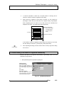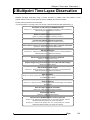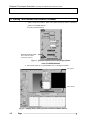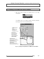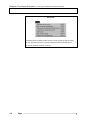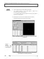
1
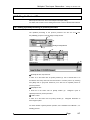
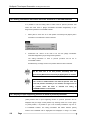
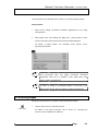
User’s Manual FLUOVIEW Multi Point Time Lapse Multi Point Time Lapse Software Ver 4.3a Petition Thank you for purchasing a XY stage control software. To ensure the safety, obtain optimum performance and familiarize yourself fully with the use of this product, we recommend that you study this manual thoroughly before operate it. This manual describes Multi Point Time Lapse software only to be used on FV300 or FV500. Together with this manual, please also read “FV300/500/TIEMPO User’s Manual” so that you can understand the overall operation method. Keep this manual in an easily accessible place near the work desk for future reference. AX6636 CAUTION ①It is prohibited to reproduce, copy or duplicate a part or the whole of this software and manual. ①The information described in this manual may be subject to change without notice. Registered Trademarks Microsoft, Microsoft Windows, Excel for Windows are registered trademarks of Microsoft Corporation. Other brand names and product names are trademarks or registered trademarks of their respective owners. Page 1 NOTATION IN THIS MANUAL NOTATION IN THIS MANUAL This manual has been compiled based on the following notation rule. Notation of Caution, Notes and Tips Notation Description Caution for preventing injuries of the user or damage to the product (including the surroundings). NOTE TIP Note for the user. Hint or one-point advice which can be a reference for the user. Notation of Menus, Command Buttons and Dialog boxes Notation [Acquire]panel Description The name of a panel, dialog box, list box or check box is enclosed inside square brackets ([ ]). <OK> button The name of a button in a panel or dialog box is enclosed inside angle brackets (< >). Notation of Mouse Operations Notation clicking Description Action of pressing then immediately releasing the mouse button double-clicking Action of clicking the mouse button successively twice. dragging Action of moving the mouse while holding the mouse button and releasing the mouse button at the desired position. (Note) In this manual, click, double-click and drag should use left button of the mouse unless otherwise specified. 2 Page NOTATION IN THIS MANUAL Notation of key operations Notation Alt + D e s c r i p t i o n The name of a keyboard key is enclosed inside Enter F1 The positive sign(+) expresses the combination of more than one key operation. For example, Alt + F1 refers to pressing the while holding the F1 key down. Direction Keys . Alt key Generic names given to the Æ , Å , Ç , È keys. Notation of system-specific terms Notation Description XY observation Refers to observation with XY scanning. (other observations) (The same principle also applies to other observations such as XZ, Xt, XYZ, XYt and XYZt.) In this manual, there are some modified panels and dialog boxes partly changed in window size and gray characters are also modified for enabling users to read them easily. Page 3 NOTES ON THE FLUOVIEW MANUALS NOTES ON THE FLUOVIEW MANUALS NOTE This instruction manual is the instruction manual for Multi Point Time Lapse software to be used on FV300, FV500 or FV-TIEMPO. Expressing “Refer to FV300/500/TIEMPO User’s Manual” in this manual means that the user is requested to read the instruction manual for the FV300, FV500 or TIEMPO the user possesses. NOTE Although the descriptions in this manual are common for the FV300 and FV500, the figures always refer to the time course software for the FV500. BEFORE USE Refer to Volume [SAFTY GUIDE] in the “FV300/500 User’s Manual” Be sure to read this volume before use. SPECIFICATIONS Refer to Volume [SAFETY GUIDE] in the “FV300/500 User’s Manual”. SYSTEM OUTLINE Refer to Volume [SYSTEM OUTLINE & SPECIFICATION] in the “FV300/500 User’s Manual”. MAINTENANCE Refer to Volume [MAINTENANCE] in the “FV300/500 User’s Manual”. TROUBLE Q & A Refer to Volume [TROUBLE Q & A] in the “FV300/500 User’s Manual”. 4 Page Contents 1 Software Description 1-1 1-1 Starting the Software ....................................................................... 1-1 1-2 Moving the Stage ............................................................................. 1-3 1-2-1 Specifying approximate position on stage ....................................................1-3 1-2-2 Moving the Stage Step by Step ....................................................................1-4 1-2-3 Moving the Stage to the Specified Coordinate Position ................................1-5 1-2-4 Moving the Stage to a Preset Position .........................................................1-6 1-2-5 Moving the Stage to an Indexed Area ..........................................................1-7 1-3 Registering the Stage Coordinate Information ........................... 1-10 1-3-1 Auto Registration of Stage Coordinate Information Specifying Index Numbers1-11 1-3-2 Auto Registration of Stage Coordinate Information Specifying Region .......1-12 1-4 Menu List ........................................................................................ 1-14 1-4-1 [XY Stage Control] Window........................................................................1-14 1-4-2 [Stage Map] Window ..................................................................................1-16 1-5 Stage Coordinate Information Markings Used in the [Stage Map] Panel ............................................................................................... 1-17 1-6 Enlarging the [Stage Map] Panel .................................................. 1-18 1-7 Changing the Settings................................................................... 1-19 1-7-1 Setting the Stage Control Parameters........................................................1-19 1-7-2 Alignment of moving direction ....................................................................1-21 1-7-3 Changing the Index Size ............................................................................1-22 1-7-4 Default setting of file name to be registered automatically .........................1-23 2 Multipoint Time-Lapse Observation 2-1 2-1 Starting This Software and Protocol Processor ........................... 2-2 2-2 Connecting This Software and Protocol Processor ..................... 2-3 2-3 Setting the Stage Coordinate Information ..................................... 2-5 2-4 Editing the Protocol File.................................................................. 2-7 2-4-1 Setting repeated processing to protocol processor ......................................2-7 2-4-2 Setting information that meets with track selected to FLUOVIEW software .2-8 2-4-3 Display of input supporting function to track of protocol processor...............2-8 2-5 Acquiring Images ............................................................................. 2-9 Contents 2-6 Z range Offset ................................................................................ 2-10 2-7 Editing Images ............................................................................... 2-11 2-8 Saving Images................................................................................ 2-11 2-9 Saving the Protocol ....................................................................... 2-11 2-10 Saving the Stage Coordinate Information ................................. 2-12 2-11 Exiting from This Software ......................................................... 2-12 2-12 Exiting from the FLUOVIEW software........................................ 2-12 3 System Requirements 3-1 Software Description / Starting the Software 1 Software Description This chapter describes the functions and setup methods of the software. 1-1 Starting the Software 1. 2. Click the <Start> button on the bottom right of the Windows screen. In case of Windows NT, select [Programs]-[Windows NT Explorer] command from [Start] menu displayed. In case of Windows 2000, select [Accessories]-[Windows Explorer] command. Windows NT or Windows2000 Explorer as shown below will be displayed. XYStage.exe 3. Double-click [XYStage.exe] of [Fluoview] folder at the drive where FLUOVIEW software is installed. Page 1-1 Software Description / Starting the Software 4. Message to confirm stage move to home position and escape of objective lens from stage appears. Click <OK> button and the stage will move to mechanical home position. [Detect the mechanical origin] check box. Remove check when stage is not moved to mechanical origin. [Escape automatically] check box Remove the check when you do not escape the objective lens from the stage (when using the Motorized microscope). 5. The main screen of the software shown below appears. <Exit> button Click to exit from the software. <Minimize> button It makes window to minimum size by turning it to icon. [Stage Map] window Shows the coordinate positions including the current stage position and registered points. [XY Stage Control] window Window for use in registration, confirmation and editing of stage coordinate information by controlling the stage. Fig. 1-1 Main Window 1-2 Page <Close> button Click to close the [Stage Map] window. Software Description / Moving the Stage 1-2 Moving the Stage Move stage to the position where the specimen is observed. 1-2-1 Specifying approximate position on stage Move stage directly to the position of observation. It is useful to move the stage to approximate position before specifying the accurate position. Double-click the position where you wish to move on panel of [Stage Map] window. [Stage Map] panel Double-click the position you wish to move inside the panel. Fig. 1-2 [Stage Map] Window If you want to register this position as the stage coordinate information, refer to section 1-3, “Registering the Stage Coordinate Information”. Page 1-3 Software Description / Moving the Stage 1-2-2 Moving the Stage Step by Step Move stage per step specified. It is useful when you wish to move the position of observation in small movement. Arrow buttons <GO> button Stage moves in arrow direction. Functions as the stop button during stage movement. Click if you want to stop movement. The movement step is the value entered in the [Step Size] text box. [Step Size] text box + button Set the distance of stage movement step per click of an arrow button. Click to return the stage to the set origin. Fig. 1-3 [XY Stage Control] Window If you want to register this position as the stage coordinate information, refer to section 1-3, “Registering the Stage Coordinate Information”. 1-4 Page Software Description / Moving the Stage 1-2-3 Moving the Stage to the Specified Coordinate Position The following operation allows the stage to be moved to the observation position by specifying its coordinates. This operation is effective when the coordinates of the observation position is already known and you want to move the stage there directly. 1. Enter the coordinates of position to which you wish to move the stage in X-axis and Y-axis at [Control Pos] text box and click <Go> button. [Control Pos] text box <GO> button Enter the coordinates of the move position in the X and Y text boxes. When clicked, the stage moves to the coordinates displayed in the [Current Pos] text box. During stage in motion, this button changes to <Stop> button. Click <Stop> button when you wish to stop. Fig. 1-4 [XY Stage Control] Window If you want to register this position as the stage coordinate information, refer to section 1-3, “Registering the Stage Coordinate Information”. Page 1-5 Software Description / Moving the Stage 1-2-4 Moving the Stage to a Preset Position This operation allows the stage to be moved to one of the coordinate positions set in advance. This operation requires stage coordinate information to be registered in advance. For details, see section1-3, “Registering the Stage Coordinate Information”. 1. Double-click column of No. of which track coordinate that is required to move is memorized in [Stage Coordinate Information Registration] sheet on [XY Stage Control] window. Up/down buttons Stage is moved to forward (up) or backward (down) coordinates of track of the track being selected in sheet. [Stage Coordinate Information Registration] sheet Stage coordinate information registered will be displayed in X, Y and Z axis. You can change each setting if you input in each text box directly. The Z-axis setting is displayed when FLUOVIEW software is started. The displayed values are obtained from the settings made with the FLUOVIEW software When No. column of track in sheet is doubleclicked, the stage moves to the coordinate of track being selected. Fig. 1-5 Main Screen The stage coordinate information contains the X- and Y-axis coordinates of the registered position. (It also includes the Z-axis coordinate when the FV300/500 is used.) 1-6 Page Software Description / Moving the Stage 1-2-5 Moving the Stage to an Indexed Area This operation allows the stage to be moved to one of the indexed areas, each of which having the specified index size (field size). This operation is effective when you want to acquire images of adjacent areas on the stage by moving the stage position to the desired areas. 1 Moving the periphery of current stage position 1. Select [Current Pos] from [Large View] menu of [Stage Map] window so that peripheral indexes (5x5) will be displayed - enlarged around center of current stage position. "Current Pos" appears here. When stage position number registered is selected from drop down list, indexes of periphery (5x5) will be displayed – enlarged around center of current stage position. Index size Current position Fig. 1-6 TIP 2. [Stage Map] Panel Enlarged The index size can be changed by the user. For details, see section 1-7-3, “Changing the Index Size”. Double-click inside grid of any index at [Stage Map] so that the stage moves to center of the said index. 3. To return to normal display, selected the [Normal View] menu in the [Stage Map] window. Page 1-7 Software Description / Moving the Stage NOTE While the [Stage Map] panel is displayed - enlarged, when zoom magnification and object lens magnification are changed on FLUOVIEW software, please select the [Edit] menu - [Refresh]. [Stage Map] will be updated. When scanning condition is changed on FLUOVIEW software and, to fan out the index size changed, it is necessary to update [Stage Map] panel. 2 Moving periphery of stage position registered 1. Select [Registration Pos] from [Large View] menu of [Stage Map] window so that the following dialog box will appear Fig. 1-7 2. [Set Registration Pos] dialog box Enter stage position number registered in [Registration No.] text box and select <Set> button. Indexes of periphery (5x5) will be displayed – enlarged around center of the registered stage position of which number was entered. Stage coordinates displayed in the center represents stage number being registered. When [Current Pos] is selected, the peripheral indexes (5x5) will be displayed - enlarged around center of current stage position. Index size Stage position at registered number Fig. 1-8 1-8 Page Enlarged [Stage Map] Panel Software Description TIP / Moving the Stage Index size can be changed. For further details, see section 1-7-3, “Changing the Index Size”. 3. If you double-click any grid of indexes on [Stage Map] panel, the stage will move to center of the said index. 4. To return to standard display, select [Normal View] of [Stage Map] window. NOTE While [Stage Map] panel is displayed – enlarged and zoom magnification and objective lens magnification are changed on FLUOVIEW software, please select [Refresh] from [Edit] menu. [Stage Map] will be updated. When scanning condition is changed on FLUOVIEW software and, to fan out the index size changed, it is necessary to update [Stage Map] panel. One Point! Select [Registration No.] from [View] menu of [Stage Map] window (check mark should appear at the item) and the number that stage coordinates are registered will appear. Select [Registration FileName] from [View] menu (check mark should appear at the item) and file name will appear inside the index (grid). File Name Registered number Page 1-9 Software Description / Registering the Stage Coordinate Information 1-3 Registering the Stage Coordinate Information The stage coordinate information contains the X- and Y-axis coordinates of the registered position. (It also includes the Z-axis coordinate when the FV300/500 is used.) 1. Move the stage to the desired position as described in section1-2, “Moving the Stage”. 2. Click the <Add Pos> button in the [XY Stage Control] window. The coordinates of the current position are added to the [Stage Coordinate Information Registration] sheet. <Add Pos> button Click to add the current stage position (XYZ coordinates) as the stage coordinate information in the sheet. Up/down buttons Click to move the stage to the coordinate position of the track before or after the cell being registered in the sheet. [Stage Coordinate Information Registration] sheet Stage coordinate information registered will be displayed in X, Y and Z axis. You can change each setting when you input in each text box directly. The Z-axis setting is displayed when FLUOVIEW software is started. The displayed values are obtained from the settings made with the FLUOVIEW software In [Comment] column, you may enter comment regarding stage coordinates. Register other desired observation positions by moving the stage to each of them and adding its stage coordinate information. 1-10 Page Software Description / Registering the Stage Coordinate Information 1-3-1 Auto Registration of Stage Coordinate Information Specifying Index Numbers If you specify reference position as center of region (center of rectangular region) to acquire coordinate information and number of indexes, you can program the region to acquire coordinate information. You can acquire adjacent images by moving the stage in every index size (size of view) programmed inside the region. 1. In the panel of the [Stage Map] window, click the mouse on the position you want to set as the reference position. A green handle appears. 2. Select [Define Region] – [by Size] from [Edit] menu of [Stage Map] window and the following sub menu will appear. Select number of indexes (column by row) to queue. Select the number of indexes to be displayed (column x row) from the sub-menu. Select [More] from sub menu and you can program row number and column number you desire. The following dialog box will appear. Enter number of rows in [Row] text box and number of columns in [Column] text box and then, select <Set> button. Fig. 1-9 [Define Region by Size] Dialog box Page 1-11 Software Description / Registering the Stage Coordinate Information 3. The stage coordinate information of each indexed area around the current position is registered automatically in order of the displayed area numbers. Index size Current position Fig. 1-10 TIP [Stage Map] Panel with Tiled Indexed Areas The index size can be changed by the user. For details, see section 1-7-3, “Changing the Index Size”. 1-3-2 Auto Registration of Stage Coordinate Information Specifying Region If you specify two points (start point and end point) that are diagonally positioned each other inside region (rectangular region) to acquire coordinate information, the region specified will be equally divided in index size (size of view) programmed. You can therefore acquire adjacent images by moving the stage in every index divided. 1-12 Page Software Description 1. / Registering the Stage Coordinate Information Select [Define Region] – [by Bounds] from [Edit] menu of [Stage Map] window and the following dialog will appear. <Start Pos> Button Set the 1st point (X and Y coordinates). <End Pos> Button Set 2nd point coordinates). (X and Y <Clear> Button It returns 1st and 2nd point to original positions. Fig. 1-11 2. Procedures are explained here. [Define Region by Bounds] Dialog box Move stage to start point of rectangular region and select <Start Pos> button. 3. Move stage to end point of rectangular region and select <End Pos> button. Stage coordinate information will be automatically registered in sequence of number inside the display. Regarding method of stage move, refer to 1-2 “Moving the Stage”. Fig. 1-12 [Stage Map] Panel with Tiled Indexed Areas Page 1-13 Software Description / Menu List 1-4 Menu List Clicking a menu name in the [XY Stage Control] window or [Stage Map] window displays the control menu, which contains commands for controlling the window. 1-4-1 [XY Stage Control] Window Menu File Sub-menu New Function Creates a new stage coordinate information registration sheet. Open Loads a CSV file to edit the stage coordinate information. Save Saves the stage coordinate information by overwriting previous data. Save As Saves the stage coordinate information being edited in a different file name and/or location. Edit Exit Exits from the application. Copy Copies the selected string, cell or track into the clipboard. Paste Inserts the data in the clipboard in the cursor position. Delete Deletes the selected string, cell or track. Re-register to PAPP Re-registers the stage coordinate information in the (It appears when FLUOVIEW protocol processor. software is linked) Register the selected When stage coordinate information is newly added to comment as base comment [Stage Coordinate Information Registration] sheet, it programs default comment registered in [Comment] column. 1-14 Page Adjust the shift of Z axis When Z position is displaced due to deflection of (It appears when FLUOVIEW microscope or ambient temperature change, it programs software is linked) the shift stroke of Z axis if Z range is adjusted. Open PAPP Track Editor It displays input supporting function to the track of protocol (It appears when FLUOVIEW processor. For further details, see 2-4-3 Display of input software is linked) supporting function to track of protocol processor. Software Description Menu View Sub-menu On Top / Menu List Function When this is checked, the [XY Stage Control] window is always displayed at the front. Registration When this is checked, the [Registration] group box is displayed. Stage Map When this is checked, the [Stage Map] panel is displayed. Separate Stage Map When this is checked, the [Stage Map] panel can be moved independently from the [XY Stage Control] panel. Options Preferences Displays the [Preference] dialog box for use in setting of details. With Protocol Processor Connects or disconnects the protocol processor. When (It appears when FLUOVIEW this is checked, the software is connected and the software is linked) [TIEMPO] group box and item “TIEMPO” in the [Stage Coordinate Information Registration] sheet are displayed. Set PP Track Info to FV with It sets setting information that meets with the track selected position movement to FOLUOVIEW software. (It appears when FLUOVIEW For further details, see 2-4-2 Setting information that meets software is linked) with track selected to FLUOVIEW software. Page 1-15 Software Description / Menu List 1-4-2 [Stage Map] Window Menu Edit Sub-menu Function Register Software Origin Registers the current position as the origin. Add Current Position Registers the current position in the [Stage Coordinate Information Registration] sheet. Define Region By Size Registers the coordinate positions of the grids (indexes) around center of the current position in the [Stage Map] panel, divided according to the index size (view size), automatically as stage coordinate information. For further details, refer to section 1-3-1 “Auto Registration of Stage Coordinate Information Specifying Index Numbers”. By Bounds Registers positions divided per index size (view size) specified in the region that is specified as region to acquire coordinate information in [Stage Map] panel as plural numbers of coordinate information automatically. For further details, refer to 1-3-2 “Auto Registration of Stage Coordinate Information Specifying Region”. Refresh Refreshes the enlarged view by obtaining the current image size and index size. This item is available when the image is being enlarged. View Registration No. It indicates number of registration for stage coordinates registered inside index in [Stage Map] panel. Large View Registration FileName It indicates file name inside index in [Stage Map] panel. Current Pos Enlarges the peripheral areas around current stage position in the [Stage Map] panel. For details, see section 1-2-5, “Moving the Stage to an Indexed Area”. Registration Pos Enlarges the peripheral areas around stage being registered in [Stage Map] panel. For further details, refer to 1-2-5, “Moving the Stage to an Indexed Area”. Normal View Returns the image in the [Stage Map] panel to the normal size. 1-16 Page Software Description / Stage Coordinate Information Markings Used in the [Stage Map] Panel 1-5 Stage Coordinate Information Markings Used in the [Stage Map] Panel The [Stage Map] panel uses the following markings to indicate the registered coordinate positions, current position, etc. Marking Name Description Origin A red handle indicates the registered origin. Current position A green handle indicates the current position. Registered point White dots indicate the positions registered in the [Stage Coordinate Information Registration] sheet. Registered point When a registered number in the [Stage Coordinate Information confirmation Registration] sheet is selected, a white handle indicates the position corresponding to the registered number. Page 1-17 Software Description / Enlarging the [Stage Map] Panel 1-6 Enlarging the [Stage Map] Panel When you select [Current Pos] from [Large View] menu of [Stage Map] window, the peripheral indexes (5x5) are displayed – enlarged around center of current stage position. In addition, when you select [Registration Pos] from [Large View] menu and specify number of stage being registered on dialog box that appears, the peripheral indexes (5x5) are displayed – enlarged at center of stage being registered. For further details, refer to 1-2-5 “Moving the Stage to an Indexed Area”. Index size Current position Fig. 1-13 TIP Enlarged [Stage Map] Panel The index size can be changed by the user. For details, see section 1-7-3, “Changing the Index Size”. To return from the enlarged display to the normal display, select the [Normal View] menu in the [Stage Map] panel. 1-18 Page Software Description / Changing the Settings 1-7 Changing the Settings This section describes how to change the stage control-related settings including the stage movement speed, stage movement acceleration, XY stage connection port, etc. The basic setting procedure is as follows: Select [Preferences] from [Option] menu on [XY Stage Control] window and display [Preference] dialog. Fig. 1-14 [Preference] Dialog Box 1-7-1 Setting the Stage Control Parameters Set the stage movement speed, stage movement acceleration, stage returning to the mechanical origin and connection port as described below. 1 Setting the stage movement speed and stage movement acceleration When a quick stage move is required, set the value of moving speed and acceleration larger and, on the other hand, if you wish to minimize the stage move in case of waferdip observation in a Petri dish, it is effective that you set the value of moving speed and acceleration smaller Select [Preferences] from [Option] menu on [XY Stage Control] window and display [Preference] dialog. [Speed] scale Select the stage movement speed. [Acceleration] text box Enter the stage movement acceleration value. Enter a value in the unit of 1.0 (mm/sec2). Page 1-19 Software Description / Changing the Settings 2 Returning the stage to the mechanical origin The mechanical origin is the origin point specific to the stage. You can set the software origin in the desired position. The stage is controlled with reference to an origin, but using the mechanism origin as the reference position makes the stage control difficult. The stage control can be made easy by setting the software origin in the position you want to use as the reference position for observation. Returning the stage to the mechanical origin is executed automatically at the start of this software. With certain stages, very small errors are accumulated after repeated movements. This operation returns the stage to the mechanical origin in order to nullify the accumulated errors. After the stage has been returned to the mechanical origin, it can be moved from there by the software control. <Go To Mechanical origin> button Click to return the stage to the mechanical origin. 3 Setting the connection port This setting is required when changing the connection port or connecting a new stage. 1. After the port to which the XY stage has been changed, open the drop-down list in the [Connect Using] group box, select the new connection port and click the <Connect> button. [Connect Using] group box Select the connection port name from the drop-down list and click the <Connect> button. 1-20 Page Software Description / Changing the Settings 1-7-2 Alignment of moving direction Alignment of moving direction is done. When the stage is moved in the state that it is not precisely connected, it would move to X or Y direction as it has been displaced from the specimen. By aligning moving direction, the displacement with coordinate can be compensated. Alignment should be executed by programming two points on specimen as reference in X direction. 1. In the [Preference] dialog box, select [Manipulation] to display the sub-panel. <1st Pos> Button Set 1st point on X direction (X and Y coordinates). <2nd Pos > Button Set 2nd point on X direction (X and Y coordinates). Procedures are explained here. <Clear > Button It returns 1st and 2nd point coordinates or alignment to original positions. Fig. 1-15 [Manipulation] Sub-panel 2. Move stage to the 1st point in X direction and select <1st Pos> button. 3. Move stage to the 2nd point in X direction and select <2nd Pos> button. The straight line that passes through two points will be aligned as X-axis. Regarding method of stage move, refer to 1-2 “Moving the Stage”. Ym 2nd point Specimen Xm 1st point When the 1st and 2nd points are specified, the software performs the following processing. 1. Assumes a right-angled triangle having the line connecting the two points as the hypotenuse and computes sin ș and cos ș of this triangle. Page 1-21 Software Description / Changing the Settings ( X2, Y2) ( X1, Y1) r Y2-Y1 X2-X1 2. Performs affine transformation using the obtained trigonometric functions. 3. Based on the results obtained above, corrects the error in coordinates between the stage and specimen as shown below. (Xa,Ya) Overall movement area T (Xp,Yp) Software coordinates Aligned stage coordinates 1-7-3 Changing the Index Size When connecting the images of adjacent areas after acquiring them, certain software is incapable of connecting them properly if the images of adjacent areas do not have some overlapped areas. The degree of overlapping between the images of adjacent area can be adjusted by changing the index size. 1. In the [Preference] dialog box, select [Index Size] to display the sub-panel. [Based on Scan Size] Check box In case that calculation of index size is required, based on scanning size as reference, check the check box. [X Index] / [Y Index] Text box Shows the index sizes in X- and Y-axis values. Shows the percentage of the index size. The setting can be changed by direct entry of the value. 1-22 Page Adjustment slider Fig. 1-16 [Index Size] Sub-panel Software Description 2. / Changing the Settings In case that calculation of index size is required, based on scanning size as reference, check the check box of [Based on Scan Size]. 3. When check box of [Based on Scan Size] is checked, you can program the percentage of index size (in left side text box of adjuster slider), using adjuster slider. Depending upon the value set, the index size will be calculated and displayed in text boxes – [X Index] and [Y Index] respectively. Actual field (White parts are the margins overlapped with the images of adjacent Y-axis index size areas) 900um Field if 90% index size X-axis index size 1000um In case that the check box of [Based on Scan Size] is not checked, you can enter the value directly in text boxes – [X Index] and [Y Index] respectively. 4. <Close> button After completing all settings, click the <Close> button on the top right of the dialog box to close it. 1-7-4 Default setting of file name to be registered automatically Format of file name to be registered automatically in [File Name] column is set at registration of stage position. 1. Select [Software] panel of [Preference] dialog box. [Directory name] Check box /Text box When you register directory for save automatically, check this box and enter directory name in text box. [File name] Check box / Text box When you register file name for save automatically, check this box and enter file name in text box. Fig. 1-17 [Software] Sub panel Page 1-23 Software Description / Changing the Settings 2. When you register directory for save automatically, check the check box of [Directory name] and enter directory name in the text box. When you assign consecutive number to directory name, see the following table 1-1 [File Name] column Registration Example] and enter the name. 3. When you register file name for save automatically, check the check box of [File Name] and enter file name in the text box. When you assign consecutive number to file name, see the following table 1-1 [File Name] column Registration Example] and enter the name. Input data to text box [Directory name] [File name] No.1 Track No.2 Track ····· No. n Track R*** R*** R001¥R001 R002¥R002 ····· R00n¥R00n R** R***** R01¥R00001 R02¥R00002 ····· R0n¥R0000n OLY R*** OLY¥R001 OLY ¥R002 ····· OLY ¥R00n (blank) OLY OLY OLY ····· OLY (blank) (blank) Table 1-1 1-24 Registration example of [File Name] Page [File Name] Registration Example Multipoint Time-Lapse Observation / 2 Multipoint Time-Lapse Observation Multipoint time-lapse observation using a protocol processor is possible when this software is used together with the FV300 or FV500 system and the FV-TIEMPO (Time Course Software). The observation procedure is as shown below. * For the operations in each step, refer to the section or manual mentioned inside parentheses (( )). Turn power on and start the FLUOVIEW software. (Sections 1-2-1, “Turning Power ON” and 1-2-2, “Starting the Software” in Volume [OPERATION INSTRUCTIONS] of the FV300/500 User’s Manual) Start this software and protocol processor. (Section 2-1, “Starting This Software and Protocol Processor”) Connect this software and protocol processor. (Section 2-2, “Connecting This Software and Protocol Processor”) Start repeated scanning and determine the XY stage coordinate information. (Section 2-3, “Setting the Stage Coordinate Information”) Edit the protocol file. (Sections 2-4-1, “Editing the Protocol” and 2-4-5, “Loading a Protocol” in Volume [OPERATION INSTRUCTIONS] of the FV300/500 User’s Manual) Set the interval and number of protocol repetitions. (Section 2-4, “Editing the Protocol File”) Acquire Images Using the Protocol Processor (XYZ and XYZT Images) (Section 2-5, “Acquiring Images”) Edit the XYZ and XYZT images. (Section 2-8-1, “Building Extended Focus Image from XYZ Images” in Volume [OPERATION INSTRUCTIONS] of the FV300/500 User’s Manual) Save the images. (Section 2-3, “Saving, Opening and Shredding Images” in Volume [OPERATION INSTRUCTIONS] of the FV300/500 User’s Manual) Save the protocol. (Section 2-4-3, “Saving the Protocol” in Volume [OPERATION INSTRUCTIONS] of the FV300/500 User’s Manual) Save the stage coordinate information. (Section 2-10, “Saving the Stage Coordinate Information”) Exit from this software. (Section 2-11, “Exiting from This Software”) Exit from the FLUOVIEW software and turn power off. (Sections 1-2-16, “Exiting from the Software” and 1-2-16, “Turning Power OFF” in Volume [OPERATION INSTRUCTIONS] of the FV300 User’s Manual, Sections 1-2-11, “Exiting from the Software” and 1-2-12, “Turning Power OFF” in Volume [OPERATION INSTRUCTIONS] of the FV500 User’s Manual) Page 2-1 Multipoint Time-Lapse Observation / Starting This Software and Protocol Processor 2-1 Starting This Software and Protocol Processor 1. Select <Protocol Processor> button from [Time Series] sub panel of [Acquire] panel on FLUOVIEW software. Protocol processor boots up. <Protocol Processor> button Click to start this software and protocol processor. Fig. 2-1 [Time Series] Sub-panel in the [Acquire] Panel of the FLUOVIEW Software 2. This software starts up. For further details, see 1-1 Starting the software. This software PAPP software Fig. 2-2 2-2 Page Display when protocol processor and this software started Multipoint Time-Lapse Observation / Connecting This Software and Protocol Processor 2-2 Connecting This Software and Protocol Processor 1. Select [With Protocol Processor] from [Option] menu on [XY Stage Control] window. Fig. 2-3 Sub-menu The [TIEMPO] group box and [Stage Coordinate Information Registration] sheet displays the [PP Track No.] and [File Name] fields. [TIEMPO] group box Set the repetition processing used by the protocol processor (For statement, etc.) here. [Set to Protocol Processor] check box When the <Add Pos> button is clicked, the creation of the protocol for the added coordinate position is enabled. [PP Track No.] field Shows the track number of the protocol processor corresponding to the current track. The protocol processor’s track is enabled when this is checked. [File Name] field Specify the image file name to be saved after executing the protocol. Fig. 2-4 [XY Stage Control] Window for TIEMPO Connection Mode Page 2-3 Multipoint Time-Lapse Observation / Connecting This Software and Protocol Processor One Point! Click [Option] menu on [PAPP] window and put a check on [Start up with XY Stage] and boot up protocol processor so that this software would automatically start up and protocol processor would be connected. 2-4 Page Multipoint Time-Lapse Observation / Setting the Stage Coordinate Information 2-3 Setting the Stage Coordinate Information While performing repeated scanning, set the stage coordinate information in the [Registration] group box. 1. Set the conditions for repeated scanning in the [Acquire] panel of the FLUOVIEW software. For details, refer to section 1-2, “Outline of LSM Observation Procedures” in Volume [OPERATION INSTRUCTIONS] of the FV300/500 User’s Manual. 2. Click the <XY Repeat> button in the [Acquire] panel of the FLUOVIEW software to execute repeated scanning. The acquired image is displayed in the [Live] panel. <XY Repeat> button 3. Adjust the image brightness. For details, refer to section 2-2-1-3-9, “Adjusting the image brightness” in <Focus> button Volume [OPERATION INSTRUCTIONS] of the FV300 User’s Manual or section 22-1-4-9, “Adjusting the image brightness” in Volume [OPERATION INSTRUCTIONS] of the FV500 User’s Manual. 4. Move the stage to an approximate area near the observation target position. In the [Stage Map] window panel, double-click on the approximate position you want to move the stage. For details, see section 1-2-1, “Moving the Stage by Specifying the Approximate Position”. 5. Using the joystick provided with the XY stage, move the stage to the approximate area near the position you want to observe. 6. Move the stage to the observation position using the arrow buttons in the [Control] group box in the [XY Stage Control] window. For details, see section 1-2-2, “Moving the Stage Step by Step”. 7. Click the <STOP SCAN> button on [Acquire] panel of FLUOVIEW software to stop repeated scanning. 8. If XYZ observation is required, set it in the [Z Stage] sub-panel in the [Acquire] panel of the FLUOVIEW software. For details, see section 2-2-2-1-1, “Setting the Z-Direction Scanning Area” in Volume [OPERATION INSTRUCTIONS] in the FV300/500 User’s Manual. Page 2-5 Multipoint Time-Lapse Observation / Setting the Stage Coordinate Information 9. <Add Pos> button Click the <Add Pos> button in the [XY Stage Control] window. The coordinate information of the current position is added in the [Coordinate Information Registration] sheet. In an interlocked operation with this software, the protocol is also added in the sheet in the [PAPP] window. 10. Repeat steps 1 to 6 for each of the coordinate positions to be observed. This software and protocol processor are set up as follows. Fig. 2-5 [XY Stage Control] window where the coordinate information is registered. Registering coordinate information using this software results in automatic creation of a “For” statement. Fig. 2-6 2-6 Page [PAPP] window where the protocol is set up automatically by registration of coordinate information Multipoint Time-Lapse Observation / Editing the Protocol File 2-4 Editing the Protocol File Edit the protocol file to be used in the multipoint time-lapse editing. For details, refer to section 2-4-2 “Editing the Protocol” in the FV-300/500 User’s Manual. 2-4-1 Setting repeated processing to protocol processor The repeated processing of the protocol processor can also be set in from the [TIEMPO] group box in the [XY Stage Control] window. (1) (3) [XY Stage Control] Window (1) [PAPP] Window (5) (4) (6) [PAPP] Window 㩿㪈㪀㩷[Interval] text box, drop down list: It works as in the same case as [PAPP] window (4). Unit of interval time is to be selected from drop down list and interval time to execute protocol by returning from [Next] track to [For] track should be put in text box for repeated process of protocol processor. 㩿㪉㪀㩷[Repeat] text box: It works as in the same case as [PAPP] window (5). Designate cycles of repeated process for protocol processor. 㩿㪊㪀㩷<Path> button: It works as in the same case as [PAPP] window (6). Designate destination to save image acquired. For further details of [PAPP] window operation, see FV300/500 User’s Manual , 2-42 Editing protocol. Page 2-7 Multipoint Time-Lapse Observation / Editing the Protocol File 2-4-2 Setting information that meets with track selected to FLUOVIEW software It is possible to set the setting value of each track for protocol processor that meets with each track in [Stage Coordinates Information Registration] on [XY Stage Control] window to FLUOVIEW software. 㪈㪅 Select [Set PP Track Info to FV with position movement] from [Option] menu and make it to the state that a check is entered. 㪉㪅 Double-click No. column of the track to be set from [Stage Coordinates Information Registration] on [XY Stage Control] window. The setting information of track to protocol processor will be set to FLUOVIEW software. Simultaneously, the stage moves to the position where the track is selected. NOTE [Set PP Track Info to FV with position movement] does not appear unless [With Protocol Processor] of [Option] menu is checked. NOTE If No. column is double-clicked in the state the [Set PP Track Info to FV with position movement] is not checked, the stage moves to the position where the track is selected but setting to FLUOVIEW software is not executed. 2-4-3 Display of input supporting function to track of protocol processor [Track] window that is input supporting function to protocol processor can be displayed from [XY Stage Control] window. By checking check box of each group on [Track] window, it is possible to get or set necessary information only from or to FLUOVIEW software. The setting information that differs between [PAPP] window and FLUOVIEW will be highlighted and displayed in orange. For details 2-8 Page Multipoint Time-Lapse Observation / Acquiring Images of [Track] window, see FV300/500 User’s manual, 2-4-2-4 Input supporting function. Display method: 㪈㪅 Select track in [Stage Coordinates Information Registration] on [XY Stage Control] window. 㪉㪅 Select [Open PAPP Track Editor] from [Edit] menu. [Track] window of track to protocol processor that meets with track selected would be displayed. For details of [Track] window, see FV300/500 User’s manual, 2-4-2-4 Input supporting function. TIP Click (mouse-right side) over [Stage Coordinates Information Registration] sheet; and it is possible to select [Open PAPP Track Editor] or display [Track] window. TIP To reflect all settings of FLUOVIEW software to the tracks in [XY Stage Control] window, select [Re-register to PAPP] from [Edit] menu. 2-5 Acquiring Images Execute the created protocol to acquire the multipoint time-lapse images. 1. <Start> button Click the <Start> button in the [PAPP] window. For details on the protocol execution, refer to section 7-4, “Executing the Protocol” in the FV-TIEMPO User’s Manual. Page 2-9 Multipoint Time-Lapse Observation / Z range Offset 2-6 Z range Offset In case that Z position is displaced due to deflection of microscope or ambient temperature change, set [Z Pos] (Current Pos) once again with use of [XY Stage Control] window. 1. Select registered number of track (stage coordinates information) to adjust Z position on [Stage Coordinates Information Registration] sheet on [XY Stage Control] window and double-click it to move the stage. 2. Select [Adjust the shift of Z axis] from [Edit] menu of [XY Stage Control] window so that the following dialog box will appear. Fig. 2-7 TIP Do mouse [Adjust the shift of Z axis] Dialog box right-click over [Stage Coordinates Information Registration] sheet on [XY Stage Control] window and select [Adjust the shift of Z axis] so that the same operation as described above can be done. 3. Select <XY Repeat> button on [Acquire] panel of FLUOVIEW software to execute repeat scanning. Acquired image will appear in [Live] panel. For details, refer to 1-2-12-6 “Repeated Scanning Operation” in Volume [OPERATION INSTRUCTIONS] of the FV300 User’s Manual or 1-2-8-6 “Repeated Scanning Operation” in Volume [OPERATION INSTRUCTIONS] of the FV500 User’s Manual. 4. Select [Z Stage] sub panel on [Acquire] panel of FLUOVIEW software. 5. Watching [Live] panel, adjust Z position, using <Z stage coarse adjustment> button or <Z stage fine adjustment> button on [Z Stage] sub panel. Shift distance of Z position (the difference between the value in [Current Pos] text box and the value in [Z Pos] of track selected with XY Stage Software will be displayed in [Z Shift] text box of [Adjust the shift of Z axis] dialog box. For details, refer to 1-2-12-7 “Setting the Multiple sections to be Observed” in Volume [OPERATION INSTRUCTIONS] of the FV300 User’s Manual or 1-2-8-7 “Setting the Multiple sections to be Observed” in 2-10 Page Multipoint Time-Lapse Observation / Editing Images Volume [OPERATION INSTRUCTIONS] of the FV500 User’s Manual. 6. Upon completion of Z position adjustment, select <Set> button on [Adjust the shift of Z axis] dialog box. Shift distance of Z position will be registered in [Z Pos] column of [Stage Coordinates Information Registration] sheet of XY Stage Software. 7. Select <STOP SCAN> button on [Acquire] panel of FLUOVIEW software so that the repeat scanning will be stopped. TIP In case that the shift distance of Z position is already known, you may enter the shift value directly in [Z Shift] text box on [Adjust the shift of Z axis] dialog box without executing scan and moving the stage to acquire the shift distance. NOTE When you use FV300/500 system that Z motor is not equipped, you cannot use [Adjust the shift of Z axis] function. 2-7 Editing Images Edit the acquired XYZ or XYZT images. For details, refer to 2-6 “Image Processing” and after in Volume after in Volume [OPERATION INSTRUCTIONS] of the FV300/500 User’s Manual. 2-8 Saving Images Save the edited images. For details, refer to 2-3-1 “Saving Images” and [OPERATION INSTRUCTIONS] of the FV300/500 User’s Manual. 2-9 Saving the Protocol Save the protocol used in the multipoint time-lapse observation in the CSV file format. For details, refer to 2-4-3 “Saving the Protocol” in Volume [OPERATION INSTRUCTIONS] of the FV300/500 User’s Manual. Page 211 Multipoint Time-Lapse Observation / Saving the Stage Coordinate Information 2-10 Saving the Stage Coordinate Information Save the stage coordinate information used in the multipoint time-lapse observation in the CSV file format. In the [XY Stage Control] window, select the [File] menu – [Save As], name the information file and save it. 2-11 Exiting from This Software In the [XY Stage Control] window, select the [File] menu – [Exit]. 2-12 Exiting from the FLUOVIEW software Exit from the FLUOVIEW software. For details, refer to 1-2-16 “Exiting from the Software” in Volume [OPERATION INSTRUCTIONS] of the FV300 User’s Manual or 1-2-11 “Exiting from the Software” in Volume [OPERATION INSTRUCTIONS] of the FV500 User’s Manual. 2-12 Page System Requirements 3 System Requirements Unit Computer system XY stage Computer Monitor Image input block Image memory Input memory Specifications Same as the FLUOVIEW FV300/500 systems. MPT-AS01-FV / MPT-AS02-FV (BIOS series - SIGMA KOKI Co., Ltd.) ProScanTM (Prior Scientific Instruments, Ltd.) ProScan is registered trademarks of Prior Scientific Instruments, Ltd. Page 3-1 OLYMPUS CORPORATION 2-43-2,Hatagaya, Shibuya-ku, Tokyo, Japan OLYMPUS OPTICAL CO.(EUROPA) GMBH. Postfach 10 49 08, 20034, Hamburg, Germany OLYMPUS AMERICA INC. 2 Corporate Center Drive, Melville, NY 11747-3157, U.S.A. OLYMPUS SINGAPORE PTE LTD. 491B River Valley Road, #12-01/04 Valley Point Office Tower, Singapore 248373 OLYMPUS OPTICAL CO. (U.K.) LTD. 2-8 Honduras Street, London EC1Y OTX, United Kingdom. OLYMPUS AUSTRALIA PTY. LTD. 104 Ferntree Gully Road, Oakleigh, Victoria, 3166, Australia This publication is printed on recycled paper. Printed in Japan 2003 10 1.3