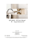
1
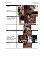
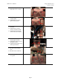
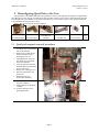
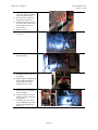
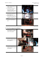
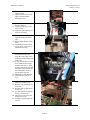
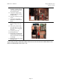
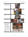
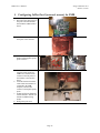
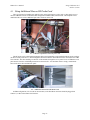
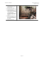
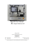
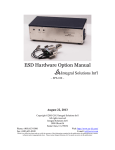
Configuring BlazerX6 Options
BlazerX6 User’s Manual Supplement
Integral Solutions Int'l
October 5, 2010
Copyright ©2009-2010 Integral Solutions Int'l
All rights reserved
Integral Solutions Int'l
3000 Olcott St
Santa Clara, CA 95054
Phone: (408) 653-0300
Fax: (408) 653-0309
Web: http://www.us-isi.com/
E-mail: [email protected]
While every effort has been made to verify the accuracy of the information contained in this publication, this publication may contain technical
and/or typographical errors. Please contact Integral Solutions Int’l to report any errors in this publication.
FMRA User’s Manual
Integral Solutions Int’l
October 5, 2010
Contents
1 RECONFIGURING AIR-CORE TO QUAD-POLE ................................................................................ 3 1.1 1.2 2 AIR –CORE MAGNET REMOVAL PROCEDURE ........................................................................................... 3 QUAD-POLE MAGNET INSTALLATION ..................................................................................................... 5 RECONFIGURING QUAD-POLE TO AIR-CORE ................................................................................ 9 2.1 2.2 QUAD-POLE MAGNET REMOVAL PROCEDURE.......................................................................................... 9 AIR-CORE MAGNET INSTALLATION....................................................................................................... 11 3 CONFIGURING 2XBAR GEN3 (INTERNAL MOUNT) FOR FMR .................................................. 14 4 CONFIGURING 2XBAR GEN3 (EXTERNAL MOUNT) FOR FMR ................................................. 16 4.1 USING ADDITIONAL PINS ON HF PROBE CARD ..................................................................................... 17 5 CONFIGURING FMR FOR STANDARD TESTING (INTERNAL MOUNT) .................................. 18 6 CONFIGURING FMR FOR STANDARD TESTING (EXTERNAL MOUNT) ................................. 20 7 RIA TESTING USING MODIFIED 2XBAR GEN3 INTERMEDIATE BOARD .............................. 21 8 RIA TESTING USING HIGH FREQUENCY PROBE CARD............................................................. 22 Page 2
FMRA User’s Manual
Integral Solutions Int’l
October 5, 2010
1 Reconfiguring Air-Core to Quad-Pole
This procedure is intended for BlazerX6 tester platform to convert from original air-core magnet ti quad-pole
X6 magnet. In preparation to this procedure it makes sense to remove the metal panels from the left and right sides
of the machine, as well as the back (plastic) cover from the top frame. These panels would need to be reinstalled
after the procedure is done.
Ensure that you have all parts for the installation.
Quad-pole base
Quad-pole probe
card base
Quad-pole Magnet
Assembly
Quad-pole Bar Arm
Left L-bracket.
or
Quad-pole magnet
cover plate
Quad-pole probe card assy
1.1 Air –core magnet removal procedure
1. Through Barcont, move the
arm all the way towards the
front of the machine.
2. Remove the vacuum gripper
from the transfer arm by
undoing 4 screws on the
gripper.
3. Through Barcont, move the
arm all the way towards the
back of the machine.
4. Close the software and click
the EMO button to turn off the
power to the stages.
5. Remove the Y/Z stages cover.
6. Disconnect and remove the
probe card.
7. Disconnect the Gen3
Intermediate board assy.
Page 3
Y/Z stage cover
FMRA User’s Manual
Integral Solutions Int’l
October 5, 2010
8. Remove the grounding
bracket.
9. Disconnect the grounding
wire from the arm.
10. Disconnect the vacuum line
from the arm.
11. Remove the arm.
12. Disconnect the magnet cable.
13. Remove 4 screws holding the
bar test assy and pull the assy
straight up. Carefully guide
the magnet cable connector in
the opening in the base.
14. Remove the gen3 filler panel.
15. Loosen the screws on top of
the remaining base, but do not
remove.
16. On the right L-bracket,
remove the horizontal
mounting screws.
17. On the right L-bracket, loosen
the two vertical screws.
18. Remove the 3 screws and take
out the left L-bracket (left side
of the base block).
19. Pull the base block straight up
and remove it.
Page 4
FMRA User’s Manual
Integral Solutions Int’l
October 5, 2010
20. If up-facing OCR camera is
present, unscrew it from the
metal plate.
1.2 Quad-Pole magnet installation
21. If up-facing OCR camera is
present, move it to location
closer to the back of the
machine.
22. Thread, but do not tighten the
screws.
23. Install the quad-pole left Lbracket to the top plate. Do
not tighten the screws.
24. Install the quad-pole base.
25. Thread and tighten four 2.5”
screws to secure the quad-pole
base.
26. Install the quad-pole magnet.
Slide the magnet cables
carefully in the opening in the
center of the base, and route
them towards the lens and out
to the back of the machine.
Page 5
FMRA User’s Manual
Integral Solutions Int’l
October 5, 2010
27. Secure the magnet to the base
using four 8-32 ¾” screws.
28. Install the quad-pole probe
card base pillar.
29. Tighten the screws on the
probe card base pillar.
30. Thread the screws in the left
L-bracket.
31. Tighten the two vertical
screws in the left L-bracket.
32. Tighten the two horizontal
screws on the left L-bracket.
33. Thread two 8-32 1” screws
into the right L-bracket.
34. Tighten the vertical screws in
the right L-bracket.
35. Tighten the horizontal screws
in the right L-bracket.
36. Install the bar arm.
37. Reconnect the grounding
wire.
38. Reconnect the vacuum line.
39. Install the quad-pole magnet
cover panel.
Page 6
FMRA User’s Manual
Integral Solutions Int’l
October 5, 2010
40. Loosen the forward limit
sensor on Y stage.
41. Release the EMO button and
turn on the machine.
42. Start Barcont in service mode.
Click “No” to “Find Homes”.
43. In 1000um increments, move
the arm forward such that
there is ~2mm clearance
between the arm and the
magnet.
44. Move the forward limit sensor
to activate at that position.
45. Move stage away and tighten
the screw on the limit sensor.
46. Restart Barcont.
47. Find Homes.
48. Find Software Limits on the Y
stage.
49. Using dial indicator, align the
Z to Y-travel tilt.
50. Check the X to Y-travel tilt of
the arm and realign if out of
spec.
51. Mount the vacuum gripper on
the arm.
52. If up-facing OCR camera is
present, turn on the vacuum
and put on a bar.
53. Align OCR camera, focus and
tighten the OCR lens to the
base. Use 1/8” to control the
camera position and 1/16”
wrench to change the lens tilt.
54. Install the probe card holder.
Page 7
FMRA User’s Manual
Integral Solutions Int’l
October 5, 2010
55. Install the Probe card
56. Realign the tester
57. Install the grounding bracket
in the available location and
readjust its Z position.
58. Install the YZ stage cover.
59. Reinstall the access panels.
As part of this procedure, the hardware limits on the Y axis are moved. The software limits must be reset,
and user should find index offset on the Y axis.
Page 8
FMRA User’s Manual
Integral Solutions Int’l
October 5, 2010
2 Reconfiguring Quad-Pole to Air-Core
This procedure is intended for BlazerX6 tester platform to convert from quad-pole X6 magnet to original 2xBar
Gen3 dual-pole air-core magnet. In preparation to this procedure it makes sense to remove the metal panels from the
left and right sides of the machine, as well as the back (plastic) cover from the top frame. These panels would need
to be reinstalled after the procedure is done.
Ensure that you have all parts for the installation.
Gen3 Magnet Base
Gen3 Filler Plate
Gen3 Bar Test
Assembly
2.1 Quad-pole magnet removal procedure
1.
2.
3.
4.
5.
6.
7.
Through Barcont, move the
arm all the way to towards the
front of the machine.
Remove the vacuum gripper
from the transfer arm by
undoing the 4 screws.
Through Barcont, move the
arm all the way towards the
back of the machine.
Close the software and click
the EMO button to turn off the
power to the stages.
Remove the Y/Z stages cover.
Disconnect and remove the
probe card.
Disconnect the Gen3
Intermediate board assy.
8.
Remove the 4 screws holding
the probe card base.
9. Pull up and remove the probe
card base.
10. Unscrew and remove the
grounding bracket.
Page 9
Gen3 Bar Arm
Left L-bracket.
Y/Z
Stage
Cover
FMRA User’s Manual
Integral Solutions Int’l
October 5, 2010
11. Loosen the grounding cable
screw and pull the grounding
cable away from the arm.
12. Disconnect the vacuum line
going to the transfer arm.
13. Unscrew the arm. The screws
are metric 3mm. The screw at
the top right of the arm is
metric 2.5mm.
14. Remove the arm.
15. Take the quad-pole magnet
cover out.
16. Remove the 4 screws holding
the magnet base.
17. Unplug the magnet cables. Use
the right-side access panel to
get to them.
18. Pull the magnet straight up. Do
this carefully and help the
cables slide out from the
magnet hole more easily.
19. From the right access panel,
remove two screws holding the
probe card pillar.
20. Loosen the other two screws
on this L-bracket (going into
the top plate).
21. From the top, remove the 4
screws holding the pillar and
pull the pillar straight up to
remove it.
Page 10
FMRA User’s Manual
Integral Solutions Int’l
October 5, 2010
22. From the left access panel,
remove two horizontal screws
in the L-bracket.
23. Loosen the vertical screws in
the L-bracket. You may
remove the L-Bracket
altogether now, but it might be
easier after the next step.
24. Remove the 4 screws holding
the base block and pull the
block straight up.
25. Remove the L-bracket on the
left side of the base block (this
could have been done in step
23).
26. If OCR Camera is present,
unscrew it from the metal
base.
2.2 Air-Core magnet installation
27. If up-facing OCR Camera is
present, then move the camera
to an alternative set of holes
(closer to the operator).
28. Install the L-bracket on the left
side of the opening (to the top
plate). A single screw is used,
do not tighten yet.
29. Install the Gen3 base block
and secure it with 2.5” screws
on the outside. Use 1” screw in
the center hole.
Page 11
FMRA User’s Manual
Integral Solutions Int’l
October 5, 2010
30. Thread two 5/8” screws into
right L-bracket.
31. Tighten vertical screws in the
right L-bracket and then
horizontal screws.
32. Thread the horizontal screws
the left L-bracket.
33. Tighten the top screw in the
left L-bracket.
34. Tighten the horizontal screws
in the left L-bracket.
35. Mount the filler panel on the
right side of the gen3 block
(top).
36. Release EMO and turn on the
tester.
37. Start Barcont software in the
service mode. Click “NO” to
Find homes message.
38. Loosen the screw holding the
forward limit sensor on Y
stage. Move the sensor closer
to the front of the machine (out
of the way).
39. In steps of 1000 um, move the
arm towards the front of the
machine until there is ~2mm
clearance between Z stage and
the magnet. Move and secure
the forward limit sensor to
activate at that position.
40. Find homes (restart Barcont).
41. Find Software Limits on Y
Axis.
42. Mount the new bar arm (use
3mm and 2.5mm screws)
43. Reconnect the grounding wire
to the arm.
44. Reconnect the vacuum line to
the bar arm.
45. Use dial indicator to align the
arm (Z to Y-travel tilt).
46. Check X to Y-travel tilt and
realign if necessary.
47. Install the vacuum gripper on
the arm.
Page 12
FMRA User’s Manual
Integral Solutions Int’l
October 5, 2010
48. Mount the air-core magnet
assembly. Carefully route the
cable through the opening in
the Gen3 base block.
49. Connect the magnet to the
available to the cable inside
the upper frame.
50. Secure the magnet assy with 4
screws.
51. Connect the intermediate
board assy to 2xBar interface
board.
If up-facing OCR camera is
not present skip to the next
step.
52. Turn on the vacuum on the
arm and mount a bar. Align
the OCR camera and tighten
the screws.
53. Install the probe card.
54. Re-align the tester.
55. Reinstall the grounding block
to the position closest to the
front of the machine and adjust
its Z height.
56. Reinstall all the panels and the
YZ stage cover.
As part of this procedure, the hardware limits on the Y axis are moved. The software limits must be reset,
and user should find index offset on the Y axis.
Page 13
FMRA User’s Manual
Integral Solutions Int’l
October 5, 2010
3 Configuring 2xBar Gen3 (internal mount) for FMR
Only the tester with EMI shielding option can be fitted with FMR option. This reconfiguration procedure
assumes that the tester such BlazerX6 was configured for regular 2xBar Gen3 testing and needs to be converted
back to high frequency pico probe / FMR testing.
This is for more extensive reconfiguration, where the front-end electronics were installed inside the machine.
1. Turn off QST-2002E
2. Remove the back panel of the
enclosure.
3. Disconnect all the cables after
the universal interface (2xBar
interface and probe card).
4. Remove covers from 2xBar
and Universal interface boards.
5. Remove the 2xBar interface
board.
6. Remove Universal Interface
board.
Page 14
FMRA User’s Manual
Integral Solutions Int’l
October 5, 2010
7. Install the metal enclosure. On
the back panel, leave two
leftmost holes open – this is
where the front end plate will
mount.
8. Install the universal and 2xBar
boards on the special plate.
9. Mount this plate to the back of
the machine.
10. Install the protective covers on
2xBar and universal interface
boards.
11. Substitute standard probe card
holder with the high frequency
probe card base.
Î
12. Connect the boards. The 2xBar
interface board connects to
FMRA box, and that in turn
connects to the left panel of
the machine to the
interconnect board.
13. From the interconnect board
the cables inside the machine
are connected to the FMR
amplifier, which in turn
connects to the high frequency
probe.
14. In BarcontÆTesterÆOptions,
enable Channel 1 and turn off
channel 0 (FMRA testing
mode).
15. Realign the probe card
Page 15
FMRA User’s Manual
Integral Solutions Int’l
October 5, 2010
4 Configuring 2xBar Gen3 (external mount) for FMR
1.
2.
Turn off QST-2002E
Disconnect the cables between
the probe card /intermediate
board and the 2xBar interface
board.
3.
Close the access panel in the
back plate of the enclosure.
4.
Substitute standard probe card
holder with the high frequency
probe card base.
Î
5.
6.
7.
8.
Connect the boards. The 2xBar
interface board connects to
FMRA box, and that in turn
connects to the left panel of
the machine to the interface
board.
From the interface board the
cables inside the machine are
connected to the FMR
amplifier, which in turn
connects to the high frequency
probe.
In BarcontÆTesterÆOptions,
enable Channel 1 and turn off
channel 0 (FMRA testing
mode).
Realign the probe card.
Page 16
FMRA User’s Manual
Integral Solutions Int’l
October 5, 2010
4.1 Using Additional Pins on HF Probe Card
There is an option for installing Aux and ELG pins on the high frequency probe card, to either apply stress or
measure additional circuits on the head while configured for FMR (or RIA) measurement. The HF probe card is
modified in this case to have additional pins and a connector on the side.
4-1 – Additional Capabilities on the HF probe card
The HF probe card is connected through 8pin cable to the intermediate card, installed beside the probe card base
(as shown on the picture above). Then through the flat ribbon cable the intermediate board is connected to the 2xBar
Gen3 interface. The cable should go to the back of the machine, through the access panel. In case of FMR the access
panel must be closed to avoid EMI penetration into the enclosure – the flat ribbon cable is simply “sandwiched”
between the access door and the back panel.
4-2 – Additional Connection to HF Probe Card
In FMR configuration, CH1 is used for measurement, so the flat ribbon connector should be plugged into
Channel 1, or JP2 on the 2xBar Gen3 interface.
.
Page 17
FMRA User’s Manual
Integral Solutions Int’l
October 5, 2010
5 Configuring FMR for Standard Testing (internal mount)
1.
2.
3.
4.
Turn off QST-2002E
Disconnect all the cables from
2xBar interface board and
Universal interface board.
Remove the protective cover
from the 2xBar and universal
Interface Boards.
Take off the front end board
panel from the back of the
machine.
5. Remove the back panel from
the enclosure.
6. Move the 2xBar and Universal
Interface boards inside the
machine to the proper location.
7. Change the probe card base to
standard.
Í
Page 18
FMRA User’s Manual
Integral Solutions Int’l
October 5, 2010
8. Install plastic protective covers
on the 2xBar and Universal
Interface boards.
9. Reconnect all the cables.
10. Install the plastic panel on the
back of the enclosure.
11. In BarcontÆTesterÆOptions,
enable Channel 0 and Channel
1 (if du-pole magnet)
If Quad-pole magnet option is
installed, then enable only
channel 0.
12. Remove the FMRApp from
the selected modules, or open
the script where FMRApp is
not enabled.
13. Realign the probe card.
Page 19
FMRA User’s Manual
Integral Solutions Int’l
October 5, 2010
6 Configuring FMR for Standard Testing (external mount)
1. Turn off QST-2002E.
2. Disconnect the 2xBar interface
ribbon cable from the FMRA
module.
3.
Open the access panel in the
back panel of the enclosure.
4.
Change the probe card base
from high frequency FMR to
standard 2xBar Gen3.
Í
5.
6.
Route the cables from 2xBar
to the Probe card base through
the access panel on the back of
the enclosure.
Secure the cable holder plate
to the standoffs where 2xBar
resided.
Page 20
FMRA User’s Manual
Integral Solutions Int’l
October 5, 2010
7 RIA Testing Using Modified 2xBar Gen3 Intermediate Board
The tester must be configured for standard testing (external or internal front-end board mount), not FMR
testing.
1.
2.
3.
4.
5.
6.
7.
8.
9.
Turn off QST-2002E and
RIA.
Change the standard probe
card base to the Gen3
Intermediate Board assy
modified for RIA.
Install the RIA satellite
module inside the enclosure.
FMR Tester should be
equipped with special adapter
plate as shown in the picture
on the right.
Connect the cable between
RIA module and RIA satellite
module (flat ribbon).
Connect the cable between the
RIA satellite module and the
Gen3 intermediate writer
board.
Turn on the RIA and QST2002E. Start software and
open a setup file.
Enable RIA2008 application
in the setup file.
Enable Channel 0 in
BarcontÆTesterÆOptions.
The standard writer test will
not be valid, they are
substituted with RIA.
Page 21
FMRA User’s Manual
Integral Solutions Int’l
October 5, 2010
8 RIA Testing Using High Frequency Probe Card
1.
2.
Turn off QST and RIA.
Install the high frequency
probe card base (if not
installed).
3.
Remove the access panel in
the back panel of the enclosure
(as in standard testing external
mount configuration)
4.
Install RIA satellite module
inside the enclosure.FMR
Tester should be equipped
with special adapter plate as
shown in the picture on the
right.
Connect the cable between
RIA module and RIA satellite
module (flat ribbon).
5.
Page 22
FMRA User’s Manual
Integral Solutions Int’l
October 5, 2010
6.
Install the high frequency
probe card.
7. Connect the cable between the
RIA satellite module and the
high frequency probe card.
8. Realign the probe card.
9. In BarcontÆTesterÆOptions
Select “1slider” per probe
location.
10. Enable RIA2008 module in the
setup file and start testing.
Page 23