1
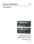
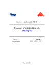
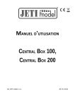
Welcome to the RCDroidBox bluetooth adapter!
Name
Description
Variant
Producer
RCDroidBox
Bluetooth adapter
JETI Duplex - external (JETI_ext)
JATAYA systems s.r.o. & JETI model s.r.o.
Device description
RCDroidBox allows real-time monitoring and recording of telemetry data transferred using JETI
Duplex or Duplex EX protocol. The system consists of both hardware and a software part. The
hardware is the actual RCDroidBox Bluetooth adapter and the software is an application running on a
device with the Android operating system, such as cell phone or tablet. The application is available
free of charge on Google Play - JATAYA systems - RCDroidBox
For active use the RCDroidBox has to be connected to a battery 4V-15V with the correct polarity and
to the Ext. connector of the RC transmitter or transmitter module.
Technical details
1
4
Operating Voltage DC (V).....................4 - 15
Typical current consumption (mA)..............20
Maximum current consumption (mA).........60
Standby current consumption (mA).............1
2
3
Operating temperature (ºC).......... -15 to +50
Relative humidity %...................................90
Dimensions (mm).........................38 x 20 x 7
BT Transmit power (dB)............................< 4
1.........Battery connector
2.........LED status indication
3.........Telemetry input connector - Ext.
4.........Internal Bluetooth antenna
Requirements
JETI Duplex
Battery
4V-15V
Android 2.3.3
and higher
Bluetooth
System interconnection
For the whole system to function properly both
4V-15V
your RC Transmitter and receiver must support
Battery
RCDroidBox
JETI Duplex or JETI Duplex EX.
The RCDroidBox and the RC transmitter must be
Ext.
connected together using the three-pin Ext.
(( Bluetooth ))
connector. The connector on the transmitter is the
cell phone
one which would otherwise be used for Jetibox
RC Transmitter
or tablet
terminal. The correct orientation of the connector
is depicted both on RCDroidBox and on the
transmitter. The connection is realized using a three-wire cable with a standard servo-connector on
both sides. A separate power supply from battery 4V-15V with the correct polarity and voltage needs
to be connected to the RCDroidBox battery connector. The final component is the cell phone or tablet
running both the operating system Android (2.3.3 or higher) and the RCDroidBox application.
Bluetooth connection
A typical Bluetooth connection range is around 10m, but this also depends on other factors such as
phone type, weather, obstacles between the RCDroidBox and the cell phone, etc. The whole system
is based on the assumption that the Android application is operated by pilot him/herself or his/her
assistant who is nearby. When used like this, there will be no problems with the Bluetooth connection.
Basics of RCDroidBox and Android application
Getting to know RCDroidBox
We suggest that you try out RCDroidBox first at home or
somewhere quiet with an internet connection. Both the RCDroidBox and the Android application are
sufficiently documented, follow well-established usage and their use is intuitive. However, it is still
better not to be distracted by worries about the model aircraft, the bright sun or a flat phone battery
etc. when trying the product out for the first time. A smaller number of active BT devices will also
make it easier to choose the right one when connecting for the first time
Android application distribution
The Android application which allows the visualization
and administration of the RCDroidBox data is available free of charge on Google Play. Even though
the application is free, Google Play requires users to create a user account. If you do not already
have a Google Play user account, then you will need to go through a simple process to set one up.
In order to install the RCDroidBox application you will need to go to Google Play, search for “JATAYA
RCDroidBox“ and then click on install. After approving the installation you will have the application
ready for use. Google Play will automatically remind you of any future updates for the application
Bluetooth connection security RCDroidBox is protected against unauthorized access using
a four digit PIN code. You will need to enter this code only once (during the so called “pairing“), as
your cell phone or tablet will remember the code. The primary purpose of this protection is to prevent
accidental or deliberate connection to your RCDroidBox by somebody else.
Firmware updates
RCDroidBox continues to be developed further. In order to provide
everybody with the most recent features, improvements and bug fixes, a so-called "firmware update
mechanism" is built into the RCDroidBox. The Android application can automatically detect if the
firmware is the most recent, and if not, it automatically offers to update it.
First start and the configuration of the device
1) Selection of the device for pairing Connect the power supply to your RCDroidBox. The
status LED indicates by periodic flashing that the device is waiting for the Bluetooth connection. In
the Android device run the application and from the main menu choose the [RCDroidBox device] →
[Find RCDroidBox device]. From the displayed list choose the device named "RCDB_NewBorn". After
the selection is done you will be forwarded back to the main menu of the application.
2) Change of the device name and PIN
You will be prompted to change the device
name and PIN on first usage of the [Telemetry], [Maps] or [Jetibox] menu items. The change of the
device name and PIN must be made as the device cannot be used if the PIN or name have the
factory default values i.e. the PIN is "1111" and the name is "RCDB_NewBorn“ or “RCDB_ReBorn“.
These must be changed.
Go to the application main menu and choose the [Telemetry] item. In approximately 5 seconds there
will be the dialog box shown prompting for the PIN entry. Enter the PIN "1111" and press [OK]. Wait
another 5 seconds for the dialog box which will prompt you for the personalized device name and
PIN. Enter the new PIN you have chosen (different from "1111") and press [Save]. Wait 30 seconds
until you will be prompted for re-entry of your new PIN. Enter your new PIN code once again.
Although the update should not take more than one minute, it is a sensitive operation
and once started it must not be aborted. The update requires a stable Bluetooth
connection between the cell phone and the RCDroidBox. Please ensure that both cell
phone and device battery are fully charged and the Bluetooth connection is stable.
3) Firmware actualization If the newer version of firmware is available for RCDroidBox the
menu item [Update firmware] is activated in the main menu. If this item is active in your application
menu, choose it and perform the actualization. The actualization of firmware begins 30s after the
layout (screen) is displayed. Wait for specified duration to expire and do not leave the screen. If the
actualization is performed correctly, or if the actualization was not requested by the program, you can
start to use your RCDroidBox device.
Main menu of Android application
Most of the application functionalities require the RCDroidBox device to be connected. With no
connection available the viewing of stored logs, stored model settings configuration and setup of
sensors and alarms will be possible. Menu items which are only usable while connected to
RCDroidBox are marked in the list below as [on-line].
Telemetry [on-line]
Models
Textual, graphical and audio data presentation
Stored models, sensors administration; Alarms
Maps [on-line]
Stored logs
Path drawing on the map
Viewing of stored logs
Jetibox [on-line]
RCDroidBox device [on-line]
Jetibox terminal
Settings (icon in top status bar)
Preferences; Advanced functionalities
Device name and PIN change; Finding new device
Properties (System menu on each layout)
Settings for the given screen layout
Telemetry display
The layout for telemetry values display is accessible from the menu [Telemetry]. The diagram shows
the position and description of the main components with their names as they will be used subsequently in the following text.
Measurement type
and the
name of
the sensor
Current
MAX 12,8
MIN 10,4
MVario - Altitude [m]
Left vertical
axis area
11,8 A
Speed
AVG
MAX
18,6
20,3
Axes display
type switch
Graph control icons
- Reset zoom, offset
- Lock zoom
- Remove measurement type
- Add measurement type
Easy Scanning ...
Model name
Scale setup
arrows
Graph area
5,14 V |
Textual menus
scan log
RCDB – RCDroidBox
TLM – telemetry input – Ext.
Right vertical
axis area
9,3 m/s
Measurement
type switch
Bluetooth | RCDB | TLM
Connection status; Green
items are active - OK. Yellow
collor indicates connection
attempts. Red – connection
failed.
Actual value of the
measurement type
Indication and control of
periodical audio output
MGPS - Speed [m/s]
Name of displayed
measurement type
Text display area of
telemetry data
Counted (derived)
values
Indication of
measurement
types available
from sensors
Voltage of the RCDroidBox
power supply
Text display area controls
The measurement type is assigned to the text display area from the menu [Connect sensor].This
menu is triggered by a long press on the text display area. Once the measurement type is assigned
to the text display area, the display parameter can be adjusted from the menu [Display options]
which is triggered by the short touch. The periodical audio output can be turned on or off by the short
touch to the repro icon, or from the [Display options] menu.
Usage of the graph display layout
Once the graph is in the [Graph basic state] the axes and the graph lines for the selected measurement types are displayed. If the [Configurational overlay] is on, then the control icons are displayed. If
the [Analytical overlay] is on, then the tools for measurements are displayed.
[Graph basic state] allows viewing the graph lines, to move the display along the time axis (to the
left or right) and to zoom on this axis. If the graph is unlocked [Lock zoom] the move and zoom are
also allowed on the vertical axes. The measurement type assigned to the axis could be changed by
the long press on the corresponding left or right [Vertical axis area].
[Zoom and move] are performed using standard Android gestures. Gestures made in the left third of
the [Graph area] will affect measurement types assigned to the left vertical axis. In a corresponding
way gestures made in the right third affect measurement types assigned to the right vertical axes. In
the middle all graph lines (measurement types) are affected.
[Scale setup arrows] allows changing the scale of the axes even if the [Lock zoom] for graph in on.
[Configurational overlay] is triggered by the short touch to the [Graph area]. Buttons [+] and [–]
controls adding and removing measurement types to/from the graph. [Lock zoom] determines if the
zoom and move on vertical axes are enabled. The [R] button resets previously applied zoom and
move. The [S][A][P] buttons shown on each of the used vertical axes determine the granularity of the
scale. A touch of the button will cycle through the [S][A][P] options.
[S] Smart – the scale of the axes is determined by the minimum and maximum of the displayed area.
[A] Automatic – the scale is determined by the minimum and maximum value of the whole log.
[P] Predefined – the scale is taken from the stored setup [Models] → [Sensors].
[Analytical overlay] is activated by a long press on the [Graph area]. This overlay offers point and
interval measurement. [Point measurement] shows values for all plotted measurement types at the
chosen point in time.
[Interval measurement] evaluates the change in the measurement type for given period of time. By
this measurement you can easily detect, for example, the climb or dive rate.
By the [Measurement type switch] the point and interval measurement types are toggled. The
measurement area can be moved by dragging. Time interval for the [Interval measurement] is
adjusted by dragging and moving the measurement area in its left or right third. The graph can be
moved even with the [Analytical overlay] displayed.
Showing the path of the model in maps
A prerequisite is the usage of the MGPS sensor. The flight path is depicted overlaid on the Google
maps display, which is only accessible when connected on-line. If used off-line, then the model path
is shown with a blank background. The depicted path indicates the altitude by the thickness of the
line, and the speed by the color. The higher the plane is then the thicker the line becomes. When the
speed of the model increases the color of the line changes from blue to red, changing back to blue as
the speed decreases.
Troubleshooting
Forgotten PIN Plug the shortcut connector into the Ext. input. Wait 1 minute while observing the
status LED. When the flashing frequency of the LED changes, then the reset to factory defaults is
complete. Now follow the instructions in the same way as initialising a new device. RCDroidBox
could not be found Repeat the search, reset the device by unplugging it. Check the voltage of the
battery while the device is connected. The voltage should not be lower than 4V. Unable to connect
to the device Restart the RCDroidBox as it might be in the sleep mode. Update the Android
application to the newest version.
Manufacturer, warranty
The device is under the warranty for a 24 month period from the purchase date, on the condition the
device was handled according to this manual and is not damaged physically. The warranty service is
provided by the manufacturer.
JATAYA systems s.r.o. wish you a happy and rewarding time using the RCDroidBox with your
model. Further more detailed and up to date documentation could be found at www.jataya.net