1
DESIGN AND CONSTRUCTION OF A ROBOT FOR
POLAR REGION NAVIGATION
By
Hans P. Harmon
B.S.- Computer Science
University of Kansas, 2001
Submitted to the Department of Electrical Engineering and Computer Science
and the Faculty of the Graduate School of the University of Kansas
in partial fulfillment of the requirements for the degree of Master of Science
Arvin Agah(Committee Chair)
Costas Tsatsoulis(Committee Member)
Chris Allen(Committee Member)
Date of Acceptance
ABSTRACT
This thesis presents how to build, weather proof, and control a robot to perform
waypoint navigation in polar regions. Several platforms are analyzed for the
ability to survive polar environmental conditions, the ease of automation, payload
capacity, and space available for extra equipment. A base platform is selected and
then analyzed to determine what is required to actuate the driving of the vehicle.
The selected vehicle then undergoes winterization, determining what modifications
allow the vehicle to perform in polar regions. A weather proof enclosure is built
to protect instruments on board the platform. Control software then performs
waypoint navigation on a test platform and the main robot in both Kansas and
Greenland.
ii
ACKNOWLEDGEMENTS
I would like to acknowledge the contributions, support and encouragement of
others who have helped me to complete my thesis. I would like to recognize my
thesis chair and adviser Dr. Arvin Agah for giving me guidance and a place
to work. Next I say thanks to Dr. Chris Allen and Dr. Costas Tsatsoulas for
serving on my committee. I also would like to recognize all of the faculty, staff,
and students on the PRISM project, for without them I would not have had the
resources necessary for completing this thesis. Particularly Dr. Prasad Gogineni,
who headed the project, my lab-mates Rich Stansbury and Eric Akers who helped
to build MARVIN and develop the API. I thank my wife Jenifer, whose support
is greatly appreciated. And finally, I thank my family and friends.
This work was supported by the National Science Foundation (grant OPP0122520), the National Aeronautics and Space Administration (grants NAG512659 and NAG5-12980), the Kansas Technology Enterprise Corporation, and
the University of Kansas.
iii
CONTENTS
LIST OF TABLES . . . . . . . . . . . . . . . . . . . . . . . . . . . . . . .
x
LIST OF FIGURES . . . . . . . . . . . . . . . . . . . . . . . . . . . . . .
xi
1. Introduction . . . . . . . . . . . . . . . . . . . . . . . . . . . . . . . . .
1
1.1
Motivation . . . . . . . . . . . . . . . . . . . . . . . . . . . . . . .
1
1.2
PRISM . . . . . . . . . . . . . . . . . . . . . . . . . . . . . . . . .
2
1.3
Approach . . . . . . . . . . . . . . . . . . . . . . . . . . . . . . .
3
1.4
Thesis Organization . . . . . . . . . . . . . . . . . . . . . . . . . .
4
2. Mobile Base Selection . . . . . . . . . . . . . . . . . . . . . . . . . . . .
5
2.1
Requirements . . . . . . . . . . . . . . . . . . . . . . . . . . . . .
5
2.2
Platform Types . . . . . . . . . . . . . . . . . . . . . . . . . . . .
6
2.2.1
Snowmobiles . . . . . . . . .
2.2.1.1 Vehicles . . . . . .
2.2.1.2 Conversion Kit . .
2.2.1.3 UGV Snowmobiles
.
.
.
.
.
.
.
.
.
.
.
.
.
.
.
.
.
.
.
.
.
.
.
.
.
.
.
.
.
.
.
.
.
.
.
.
.
.
.
.
.
.
.
.
.
.
.
.
.
.
.
.
.
.
.
.
.
.
.
.
.
.
.
.
.
.
.
.
7
7
7
9
2.2.2
ATVs . . . . . . . . .
2.2.2.1 Vehicles . . .
2.2.2.2 Winterization
2.2.2.3 UGV ATVs .
.
.
.
.
.
.
.
.
.
.
.
.
.
.
.
.
.
.
.
.
.
.
.
.
.
.
.
.
.
.
.
.
.
.
.
.
.
.
.
.
.
.
.
.
.
.
.
.
.
.
.
.
.
.
.
.
.
.
.
.
.
.
.
.
.
.
.
.
11
11
13
14
2.2.3
Amphibious ATVs . . . . . . . . . . . . . . . . . . . . . .
2.2.3.1 Vehicles . . . . . . . . . . . . . . . . . . . . . . .
2.2.3.2 UGV Amphibious ATVs . . . . . . . . . . . . . .
17
19
20
2.2.4
Remote Controlled Tanks . . . . . . . . . . . . . . . . . .
22
2.2.5
Customized Vehicles
2.2.5.1 Nomad . .
2.2.5.2 Dante . . .
2.2.5.3 Mars Rover
.
.
.
.
23
24
25
25
Base Selection . . . . . . . . . . . . . . . . . . . . . . . . . . . . .
28
2.3
.
.
.
.
.
.
.
.
.
.
.
.
iv
.
.
.
.
.
.
.
.
.
.
.
.
.
.
.
.
.
.
.
.
.
.
.
.
.
.
.
.
.
.
.
.
.
.
.
.
.
.
.
.
.
.
.
.
.
.
.
.
.
.
.
.
.
.
.
.
.
.
.
.
.
.
.
.
.
.
.
.
.
.
.
.
.
.
.
.
.
.
.
.
3. Actuation . . . . . . . . . . . . . . . . . . . . . . . . . . . . . . . . . .
34
3.1
Requirements . . . . . . . . . . . . . . . . . . . . . . . . . . . . .
34
3.2
Measurements . . . . . . . . . . . . . . . . . . . . . . . . . . . . .
36
3.3
Motors . . . . . . . . . . . . . . . . . . . . . . . . . . . . . . . . .
38
3.3.1
Mechanical vs. Electromagnetic . . . . . . . . . . . . . . .
38
3.3.2
Linear versus Angular . . . . . . . . . . . . . . . . . . . .
38
3.3.3
Comparison . . . . . . . . . . . . . . . . . . . . . . . . . .
41
Motor Control . . . . . . . . . . . . . . . . . . . . . . . . . . . . .
41
3.4.1
Microcontroller . . . . . . . . . . . . . . . . . . . . . . . .
45
3.4.2
Computer . . . . . . . . . . . . . . . . . . . . . . . . . . .
45
4. Winterization . . . . . . . . . . . . . . . . . . . . . . . . . . . . . . . .
46
3.4
4.1
4.2
4.3
Protective Shell . . . . . . . . . . . . . . . . . . . . . . . . . . . .
46
4.1.1
Standard Additions . . . . . . . . . . . . . . . . . . . . . .
46
4.1.2
Carbon Fiber . . . . . . . . . . . . . . . . . . . . . . . . .
47
4.1.3
Metal . . . . . . . . . . . . . . . . . . . . . . . . . . . . .
48
4.1.4
T-slotted Extrusions . . . . . . . . . . . . . . . . . . . . .
48
Sealing . . . . . . . . . . . . . . . . . . . . . . . . . . . . . . . . .
48
4.2.1
Rubber
. . . . . . . . . . . . . . . . . . . . . . . . . . . .
48
4.2.2
Automotive Weather Stripping . . . . . . . . . . . . . . .
49
4.2.3
Silicone . . . . . . . . . . . . . . . . . . . . . . . . . . . .
49
4.2.4
Quick Weld . . . . . . . . . . . . . . . . . . . . . . . . . .
50
4.2.5
Air Filters . . . . . . . . . . . . . . . . . . . . . . . . . . .
50
Engine Adjustments . . . . . . . . . . . . . . . . . . . . . . . . .
50
4.3.1
Generator Exhaust . . . . . . . . . . . . . . . . . . . . . .
50
4.3.2
Re-Jetting . . . . . . . . . . . . . . . . . . . . . . . . . . .
50
4.3.3
Oil . . . . . . . . . . . . . . . . . . . . . . . . . . . . . . .
51
4.3.4
Engine Weather Kit
51
. . . . . . . . . . . . . . . . . . . . .
v
5. Software . . . . . . . . . . . . . . . . . . . . . . . . . . . . . . . . . . .
52
5.1
Background . . . . . . . . . . . . . . . . . . . . . . . . . . . . . .
52
5.2
Design . . . . . . . . . . . . . . . . . . . . . . . . . . . . . . . . .
54
5.2.1
Device . . . . . . . . . . . . . . . . . . . . . . . . . . . . .
54
5.2.2
Abstract Sensor . . . .
5.2.2.1 Position . . .
5.2.2.2 GPS . . . . .
5.2.2.3 Heading . . .
5.2.2.4 Tilt . . . . .
5.2.2.5 Temperature
5.2.2.6 Distance . . .
5.2.2.7 Bump . . . .
5.2.2.8 Image . . . .
5.2.2.9 Other Sensors
5.2.3
.
.
.
.
.
.
.
.
.
.
.
.
.
.
.
.
.
.
.
.
.
.
.
.
.
.
.
.
.
.
.
.
.
.
.
.
.
.
.
.
.
.
.
.
.
.
.
.
.
.
.
.
.
.
.
.
.
.
.
.
.
.
.
.
.
.
.
.
.
.
.
.
.
.
.
.
.
.
.
.
.
.
.
.
.
.
.
.
.
.
.
.
.
.
.
.
.
.
.
.
.
.
.
.
.
.
.
.
.
.
.
.
.
.
.
.
.
.
.
.
.
.
.
.
.
.
.
.
.
.
.
.
.
.
.
.
.
.
.
.
56
57
58
59
61
61
62
65
65
65
Extension to Sensor . . . .
5.2.3.1 Simple Sensor . .
5.2.3.2 Logging and Logs
5.2.3.3 Remote Sensing .
. . . . . . .
. . . . . . .
as Sensors .
. . . . . . .
.
.
.
.
.
.
.
.
.
.
.
.
.
.
.
.
.
.
.
.
.
.
.
.
.
.
.
.
.
.
.
.
.
.
.
.
.
.
.
.
.
.
.
.
66
66
66
67
5.2.4
Actuation . . . . . . . .
5.2.4.1 Motor . . . . .
5.2.4.2 Switches . . . .
5.2.4.3 Null Actuators
.
.
.
.
5.2.5
System
5.2.5.1
5.2.5.2
5.2.5.3
5.2.5.4
5.2.5.5
5.2.5.6
5.2.5.7
.
.
.
.
.
.
.
.
.
.
.
.
.
.
.
.
.
.
.
.
.
.
.
.
.
.
.
.
.
.
.
.
.
.
.
.
.
.
.
.
.
.
.
.
.
.
.
.
.
.
.
.
.
.
.
.
.
.
.
.
.
.
.
.
.
.
.
.
.
.
.
.
.
.
.
.
.
.
.
.
.
.
.
.
.
.
.
.
.
.
.
.
.
.
.
.
.
.
.
.
.
.
.
.
.
.
.
.
.
.
.
.
.
.
.
.
.
.
68
69
70
70
. . . . . . . . . . . . . . . . .
Pan-and-Tilt Zoom Camera
Movement2D . . . . . . . .
Joystick Control . . . . . .
Navigator . . . . . . . . . .
Mobile Radar Navigator . .
Sensor Fusion . . . . . . . .
Systems . . . . . . . . . . .
.
.
.
.
.
.
.
.
.
.
.
.
.
.
.
.
.
.
.
.
.
.
.
.
.
.
.
.
.
.
.
.
.
.
.
.
.
.
.
.
.
.
.
.
.
.
.
.
.
.
.
.
.
.
.
.
.
.
.
.
.
.
.
.
.
.
.
.
.
.
.
.
.
.
.
.
.
.
.
.
.
.
.
.
.
.
.
.
.
.
.
.
.
.
.
.
71
72
78
80
81
83
85
87
5.2.6
Health Monitoring . . . . . . . . . . . . . . . . . . . . . .
87
5.2.7
Event Handling . . . . . . . . . . . . . . . . . . . . . . . .
88
vi
.
.
.
.
.
.
.
.
.
.
.
.
.
.
5.2.8
Remote Sensing and Control . . . . . . . . . . . . . . . . .
89
Application . . . . . . . . . . . . . . . . . . . . . . . . . . . . . .
91
6. Implementation . . . . . . . . . . . . . . . . . . . . . . . . . . . . . . .
93
5.3
6.1
Actuation . . . . . . . . . . . . . . . . .
6.1.1 MAXATV . . . . . . . . . . . . .
6.1.2 Power . . . . . . . . . . . . . . .
6.1.3 Actuators - Linmot Motors . . . .
6.1.4 Computer - GoBook Max Laptop
6.2
Sensors . . . . . . . . . . . . . . .
6.2.1 Topcon GPS . . . . . . . .
6.2.2 MotionPak II Gyroscope .
6.2.3 TCM 2 . . . . . . . . . . .
6.2.4 Sick Laser Range Finder .
6.2.5 Pelco Camera + Axis 2400
6.2.6 WS2000 Weather Station .
6.2.7 Fuel Sensors . . . . . . . .
6.3
Weather Proofing . . . . . . . . . . . . . . . . . . . . . . . . . . . 105
6.3.1 Shell . . . . . . . . . . . . . . . . . . . . . . . . . . . . . . 105
6.3.2 Sealing . . . . . . . . . . . . . . . . . . . . . . . . . . . . . 108
6.4
Finished Product . . . . . . . . . . . . . . . . . . . . . . . . . . . 113
6.5
Software Control Systems . . .
6.5.1 Position2Heading Sensor
6.5.2 Movement2D . . . . . .
6.5.3 Joystick Control . . . . .
6.5.4 Simple Navigator . . . .
6.5.5 Obstacle Avoidance . . .
6.5.6 Mobile Radar . . . . . .
6.5.7 Remote Control . . . . .
6.6
SAR Tracked Vehicle . . . . . . . . . . . . . . . . . . . . . . . . . 117
6.6.1 Topcon GPS . . . . . . . . . . . . . . . . . . . . . . . . . . 117
6.6.2 Heads Up Display . . . . . . . . . . . . . . . . . . . . . . . 117
vii
.
.
.
.
.
.
.
.
.
.
.
.
.
.
.
.
.
.
.
.
.
.
.
.
.
.
.
.
.
.
.
.
.
.
.
.
.
.
.
.
.
.
.
.
.
.
.
.
.
.
.
.
.
.
.
.
.
.
.
.
.
.
.
93
93
94
94
95
. . . . . . . .
. . . . . . . .
. . . . . . . .
. . . . . . . .
. . . . . . . .
Video Server
. . . . . . . .
. . . . . . . .
.
.
.
.
.
.
.
.
.
.
.
.
.
.
.
.
.
.
.
.
.
.
.
.
.
.
.
.
.
.
.
.
.
.
.
.
.
.
.
.
.
.
.
.
.
.
.
.
.
.
.
.
.
.
.
.
.
.
.
.
.
.
.
.
.
.
.
.
.
.
.
.
.
.
.
.
.
.
.
.
97
97
97
103
104
104
105
105
.
.
.
.
.
.
.
.
.
.
.
.
.
.
.
.
.
.
.
.
.
.
.
.
.
.
.
.
.
.
.
.
.
.
.
.
.
.
.
.
.
.
.
.
.
.
.
.
.
.
.
.
.
.
.
.
.
.
.
.
.
.
.
.
.
.
.
.
.
.
.
.
.
.
.
.
.
.
.
.
.
.
.
.
.
.
.
.
.
.
.
.
.
.
.
.
.
.
.
.
.
.
.
.
.
.
.
.
.
.
.
.
.
.
.
.
.
.
.
.
.
.
.
.
.
.
.
.
.
.
.
.
.
.
.
.
.
.
.
.
.
.
.
.
.
.
.
.
.
.
.
.
.
.
.
.
.
.
.
115
115
115
115
116
116
116
117
7. Evaluation . . . . . . . . . . . . . . . . . . . . . . . . . . . . . . . . . . 120
7.1
Simulation . . . . . . . . . . . . . . . . . . . . . . . . . . . . . . . 120
7.2
Testing Platform - Bob . . . . . . . . . . . . . . . . . . . . . . . . 121
7.3
7.2.1
Nomadic Scout . . . . . . . . . . . . . . . . . . . . . . . . 122
7.2.2
Sony Vaio Picturebook . . . . . . . . . . . . . . . . . . . . 122
7.2.3
Optional Equipment . . . . . . . . . . . . . . . . . . . . . 122
7.2.3.1 Garmin GPS . . . . . . . . . . . . . . . . . . . . 122
7.2.3.2 MotionPak II . . . . . . . . . . . . . . . . . . . . 123
7.2.4
Local Joystick Control . . . . . . . . . . . . . . . . . . . . 123
7.2.5
Remote Joystick Control . . . . . . . . . . . . . . . . . . . 123
7.2.6
Remote Sensing . . . . . . . . . . . . . . . . . . . . . . . . 123
7.2.7
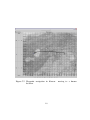
Waypoint Navigation . . . . . . . . . . . . . . . . . . . . . 124
7.2.8
Mobile Radar Navigation . . . . . . . . . . . . . . . . . . . 124
7.2.9
Obstacle Avoidance . . . . . . . . . . . . . . . . . . . . . . 124
MARVIN 2003 Results . . . . . . . . . . . . . . . . . . . . . . . . 124
7.3.1
Vehicle Performance . . . . . . . . . . . . . . . . . . . . . 125
7.3.2
Automation . . . . . . . . . .
7.3.2.1 Motor . . . . . . . .
7.3.2.2 Control . . . . . . .
7.3.2.3 GoBook Max Laptop
.
.
.
.
.
.
.
.
.
.
.
.
.
.
.
.
.
.
.
.
.
.
.
.
.
.
.
.
.
.
.
.
.
.
.
.
.
.
.
.
.
.
.
.
.
.
.
.
.
.
.
.
.
.
.
.
.
.
.
.
.
.
.
.
125
125
125
126
7.3.3
WeatherProofing . . . . . . .
7.3.3.1 Shell . . . . . . . . .
7.3.3.2 Silicone . . . . . . .
7.3.3.3 Weather Stripping .
7.3.3.4 Rubber Seals . . . .
7.3.3.5 Quick Weld . . . . .
7.3.3.6 Engine Weather Kit
7.3.3.7 Oil . . . . . . . . . .
7.3.3.8 High Altitude Jets .
7.3.3.9 Air Filters . . . . . .
.
.
.
.
.
.
.
.
.
.
.
.
.
.
.
.
.
.
.
.
.
.
.
.
.
.
.
.
.
.
.
.
.
.
.
.
.
.
.
.
.
.
.
.
.
.
.
.
.
.
.
.
.
.
.
.
.
.
.
.
.
.
.
.
.
.
.
.
.
.
.
.
.
.
.
.
.
.
.
.
.
.
.
.
.
.
.
.
.
.
.
.
.
.
.
.
.
.
.
.
.
.
.
.
.
.
.
.
.
.
.
.
.
.
.
.
.
.
.
.
.
.
.
.
.
.
.
.
.
.
.
.
.
.
.
.
.
.
.
.
.
.
.
.
.
.
.
.
.
.
.
.
.
.
.
.
.
.
.
.
127
127
127
127
128
128
128
128
129
129
7.3.4
2003 Assessment . . . . . . . . . . . . . . . . . . . . . . . 129
viii
7.4
MARVIN 2004 Results . . . . . . . . . . . . . . . . . . . . . . . . 129
7.4.1
Weather Proofing . . . . . . . . . . . . . . . . . . . . . . . 130
7.4.2
Waypoint Navigation . . .
7.4.2.1 Kansas Tests . .
7.4.2.2 Greenland . . . .
7.4.2.3 Overall Accuracy
7.4.2.4 2004 Assessment
.
.
.
.
.
.
.
.
.
.
.
.
.
.
.
.
.
.
.
.
.
.
.
.
.
.
.
.
.
.
.
.
.
.
.
.
.
.
.
.
.
.
.
.
.
.
.
.
.
.
.
.
.
.
.
.
.
.
.
.
.
.
.
.
.
.
.
.
.
.
.
.
.
.
.
.
.
.
.
.
.
.
.
.
.
.
.
.
.
.
130
130
131
157
157
8. Conclusion . . . . . . . . . . . . . . . . . . . . . . . . . . . . . . . . . . 159
8.1
Summary . . . . . . . . . . . . . . . . . . . . . . . . . . . . . . . 159
8.2
Contributions . . . . . . . . . . . . . . . . . . . . . . . . . . . . . 159
8.3
Limitations . . . . . . . . . . . . . . . . . . . . . . . . . . . . . . 159
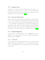
8.4
Future Work . . . . . . . . . . . . . . . . . . . . . . . . . . . . . . 160
ix
LIST OF TABLES
2.1
Vehicle requirements. . . . . . . . . . . . . . . . . . . . . . . . . . .
6
2.2
Information on snowmobiles. . . . . . . . . . . . . . . . . . . . . . .
29
2.3
Information on ATVs. . . . . . . . . . . . . . . . . . . . . . . . . . .
30
2.4
Information on amphibious ATVs. . . . . . . . . . . . . . . . . . . .
31
2.5
Information on tanks and robots.
. . . . . . . . . . . . . . . . . . .
32
3.1
Linmot inear actuators. . . . . . . . . . . . . . . . . . . . . . . . . .
42
3.2
Linmot inear actuators. . . . . . . . . . . . . . . . . . . . . . . . . .
43
3.3
Danaher linear actuators. . . . . . . . . . . . . . . . . . . . . . . . .
44
5.1
S curve state transition calculations. . . . . . . . . . . . . . . . . . .
85
5.2
Spiral state transition calculations. . . . . . . . . . . . . . . . . . . .
86
7.1
Raw waypoint data. . . . . . . . . . . . . . . . . . . . . . . . . . . . 158
x
LIST OF FIGURES
2.1
Arctic Cat F5 performance snowmobile. . . . . . . . . . . . . . . . .
8
2.2
Arctic Cat Bearcat Widetrack touring snowmobile. . . . . . . . . . .
8
2.3
Ski to wheel conversion kit for snowmobiles. . . . . . . . . . . . . .
9
2.4
Vision of robotic snowmobile system. . . . . . . . . . . . . . . . . .
10
2.5
Yamaha Big Bear. . . . . . . . . . . . . . . . . . . . . . . . . . . . .
11
2.6
Arctic Cat 500 BTX. . . . . . . . . . . . . . . . . . . . . . . . . . .
12
2.7
Gorilla Electric ATV. . . . . . . . . . . . . . . . . . . . . . . . . . .
13
2.8
SnoTraxx ATV conversion kit. . . . . . . . . . . . . . . . . . . . . .
14
2.9
LiteFoot ATV track conversion. . . . . . . . . . . . . . . . . . . . .
15
2.10
CMU’s Lewis from the CyberScout project. . . . . . . . . . . . . . .
16
2.11
Gryphon I internals. . . . . . . . . . . . . . . . . . . . . . . . . . . .
17
2.12
Gryphon III with field arm. . . . . . . . . . . . . . . . . . . . . . . .
18
2.13
Recreatives Industriess’ MaxATV. . . . . . . . . . . . . . . . . . . .
19
2.14
Agro Bigfoot. . . . . . . . . . . . . . . . . . . . . . . . . . . . . . .
20
2.15
GECKO UGV. . . . . . . . . . . . . . . . . . . . . . . . . . . . . . .
21
2.16
Autonomous Solutions’s Predator. . . . . . . . . . . . . . . . . . . .
22
2.17
AAVP7A Amphibious RC Tank . . . . . . . . . . . . . . . . . . . .
23
2.18
CMU’s Nomad. . . . . . . . . . . . . . . . . . . . . . . . . . . . . .
24
2.19
CMU’s Dante II. . . . . . . . . . . . . . . . . . . . . . . . . . . . . .
26
2.20
NASA’s Spirit rover. . . . . . . . . . . . . . . . . . . . . . . . . . .
27
2.21
The original Buffalo, prior to modifications. . . . . . . . . . . . . . .
33
xi
3.1
Lever controls for skid-steering driving for a MaxATV. . . . . . . . .
35
3.2
Force Five force measuring tool . . . . . . . . . . . . . . . . . . . .
36
3.3
Posible motor points. . . . . . . . . . . . . . . . . . . . . . . . . . .
37
3.4
Top left: medium DC motor, top right: car window motor, bottom:
AC washing machine motor. . . . . . . . . . . . . . . . . . . . . . .
39
3.5
Linmot eletromagnetic motor. . . . . . . . . . . . . . . . . . . . . .
40
4.1
Scale carbon fiber shell. . . . . . . . . . . . . . . . . . . . . . . . . .
47
4.2
Automotive weather stripping. . . . . . . . . . . . . . . . . . . . . .
49
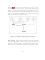
5.1
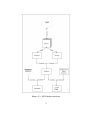
API design structure. . . . . . . . . . . . . . . . . . . . . . . . . . .
55
5.2
Position display. . . . . . . . . . . . . . . . . . . . . . . . . . . . . .
58
5.3
Aerial photo adjusted for use in a GIS system. . . . . . . . . . . . .
60
5.4
Heading sensor display. . . . . . . . . . . . . . . . . . . . . . . . . .
61
5.5
Tilt sensor display. . . . . . . . . . . . . . . . . . . . . . . . . . . .
62
5.6
Temperature sensor display. . . . . . . . . . . . . . . . . . . . . . .
63
5.7
Distance sensor is the outline, a small line from the center shows
heading, and the position is indicated by the coordinates . . . . . .
64
5.8
Actuator class hierarchy. . . . . . . . . . . . . . . . . . . . . . . . .
68
5.9
The PTZ camera. . . . . . . . . . . . . . . . . . . . . . . . . . . . .
74
5.10
Schematic of a pan-and-tilt zoom camera. . . . . . . . . . . . . . . .
76
5.11
Pan-and-tilt zoom from the Pelco camera. . . . . . . . . . . . . . . .
77
5.12
Movement2D: Differential drive, skid steering, and Akerman control
systems. . . . . . . . . . . . . . . . . . . . . . . . . . . . . . . . . .
79
5.13
Navigation working with obstacle avoidance. . . . . . . . . . . . . .
82
5.14
S curve movement pattern. . . . . . . . . . . . . . . . . . . . . . . .
84
5.15
Spiral movement pattern. . . . . . . . . . . . . . . . . . . . . . . . .
86
xii
5.16
Remote wrapping of a sensor . . . . . . . . . . . . . . . . . . . . . .
92
6.1
Motor mount design, side view.
. . . . . . . . . . . . . . . . . . . .
95
6.2
Motor mount design, front view. . . . . . . . . . . . . . . . . . . . .
96
6.3
Replacement seat design. . . . . . . . . . . . . . . . . . . . . . . . .
97
6.4
Installed actuators. . . . . . . . . . . . . . . . . . . . . . . . . . . .
98
6.5
Power required to control MARVIN. Samples every millimeter of
movement. . . . . . . . . . . . . . . . . . . . . . . . . . . . . . . . .
99
6.6
Gobook Max, covered in ice after being dropped on the snow. . . . . 100
6.7
Topcon GPS rack mount box. . . . . . . . . . . . . . . . . . . . . . 101
6.8
Dimension drawing of the MotionPak II. . . . . . . . . . . . . . . . 102
6.9
TCM2 multi-sensor. . . . . . . . . . . . . . . . . . . . . . . . . . . . 103
6.10
SICK LMS221 outdoor laser range finder. . . . . . . . . . . . . . . . 104
6.11
Pelco Espirit pan-and-tilt and zoom camera. . . . . . . . . . . . . . 106
6.12
Rainwise WS2000 weather station. . . . . . . . . . . . . . . . . . . . 107
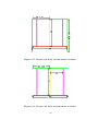
6.13
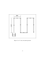
Frame front view, measurements in inches. . . . . . . . . . . . . . . 108
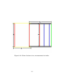
6.14
Frame side view, measurements in inches. . . . . . . . . . . . . . . . 109
6.15
Frame top view. . . . . . . . . . . . . . . . . . . . . . . . . . . . . . 110
6.16
Frame bottom view, measurements in inches. . . . . . . . . . . . . . 111
6.17
Frame rack front, measurements in inches. . . . . . . . . . . . . . . 112
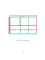
6.18
Frame rack back, measurements in inches. . . . . . . . . . . . . . . . 112
6.19
Frame back view,, measurements in inches. . . . . . . . . . . . . . . 113
6.20
MARVIN fully assembled for the Greenland 2004 field season. . . . . 114
6.21
Information display window for a human to track vehicles and
distances between them. . . . . . . . . . . . . . . . . . . . . . . . . 119
xiii
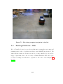
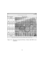
7.1
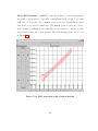
Bob doing waypoint navigation in the lab. . . . . . . . . . . . . . . 121
7.2
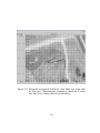
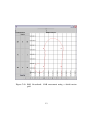
Waypoint navigation in Kansas: first test run, error threshold was set
at 5 meters. . . . . . . . . . . . . . . . . . . . . . . . . . . . . . . . 133
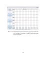
7.3
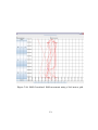
Waypoint navigation in Kansas: driving out about 80 meters,
returning, and driving back. . . . . . . . . . . . . . . . . . . . . . . 134
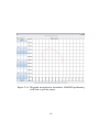
7.4
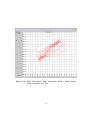
Waypoint navigation in Kansas: 180 degree turn then driving across
assvault and grass terrain. . . . . . . . . . . . . . . . . . . . . . . . 135
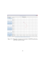
7.5
Waypoint navigation in Kansas: moving to the 20 yard line. . . . . . 136
7.6
Waypoint navigation in Kansas: moving to a base location. . . . . . 137
7.7
Waypoint navigation in Kansas: moving to a known location. . . . . 138
7.8
Waypoint navigation in Kansas: full 180 degree turn test then
followed by a driving to a base location . . . . . . . . . . . . . . . . 139
7.9
Waypoint navigation in Kansas: first SAR test using 30m by 15m
grid. Unfortunately orientation aimed the S curve into the trees,
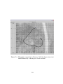
ending the test prematurely. . . . . . . . . . . . . . . . . . . . . . . 140
7.10
Waypoint navigation in Kansas: driving to a known location. . . . . 141
7.11
Waypoint navigation in Kansas: 20m by 20m SAR S curve navigation. 142
7.12
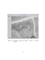
Waypoint navigation in Greenland: loop occurred because of a too
high of a threshold. MARVIN circled the target to try to get close. . 143
7.13
Waypoint navigation in Greenland: MARVIN moves to the bottom
point then to the top and back to the bottom. . . . . . . . . . . . . 144
7.14
Waypoint navigation in Greenland: MARVIN performing a full 180
to get the target. . . . . . . . . . . . . . . . . . . . . . . . . . . . . 145
7.15
Waypoint navigation in Greenland: MARVIN performing a full 180
to get the target. . . . . . . . . . . . . . . . . . . . . . . . . . . . . 146
7.16
Waypoint navigation in Greenland: 1km drive out and two 500m
drives back. . . . . . . . . . . . . . . . . . . . . . . . . . . . . . . . 147
7.17
Waypoint navigation in Greenland: 884.6 meter drive to a waypoint. 148
xiv
7.18
Waypoint navigation in Greenland: driving to a waypoint and then
human drive to a slightly different location. . . . . . . . . . . . . . . 149
7.19
Waypoint Navigation Greenland: waypoint drives to perform SAR
movement. . . . . . . . . . . . . . . . . . . . . . . . . . . . . . . . . 150
7.20
Waypoint Navigation Greenland: Waypoint drives 2km to SAR data
collection point. . . . . . . . . . . . . . . . . . . . . . . . . . . . . . 151
7.21
SAR Greenland: SAR movement using a 20x20 meter grid. . . . . . 153
7.22
SAR Greenland: SAR movement using a 50x1 meter grid. . . . . . . 154
7.23
SAR Greenland: SAR movement using a 100x1 meter, with waypoints
in a line. . . . . . . . . . . . . . . . . . . . . . . . . . . . . . . . . . 155
7.24
SAR movement with a human driving.
1
. . . . . . . . . . . . . . . . 156
1. Introduction
This thesis presents the details for construction of an uninhabited ground vehicle
(UGV) for arctic environments. It answers the question of what platforms work
in polar environments and what needs to be done to actuate and control such
platform. In order to perform waypoint navigation using sensor and actuators
added to the platform.
1.1
Motivation
What is an uninhabited ground vehicle (UGV)? UGV is any ground vehicle where
a human driver is not in the vehicle. UGVs cover all forms of control from
teleoperation to fully autonomous vehicles. UGVs have been used by industry and
government for some time and have proven useful in tasks dangerous to humans,
such as land mine detection and space exploration.
The UGV for this thesis is constructed to handle arctic environments. Not
only are arctic environments difficult for humans to live in, they are difficult to
navigate in. Constructing a roving vehicle will eliminate tasks that are currently
done by sending people out into the arctic environment. Such a vehicle will need
to survive the weather in the arctic regions as well as protect the equipment that
it carries. This thesis will cover selection of a base platform, actuation, weather
proofing, and software control systems of the platform.
Base platform selection considers the requirements needed to survive arctic
conditions as well as space needs, among other constraints. During selection,
possible vehicles are compared to the requirements. The thesis includes a brief
look at simulation of some of the platform designs.
The actuation of the platform covers all the steps of bringing the selected
1
platform under computer control. Tasks include motor selection and installation
and choice of hardware to use for computer controls.
Winterization focuses on the need to control the environment inside the
rover. This process covers building a shell and protecting all the gaps which snow
can get in.
The software control system examines how to design a hardware abstraction
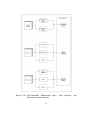
layer for automated systems. The software is used to perform waypoint navigation
on multiple platforms.
The UGV in this thesis is being used as part of the PRISM project and it
will help to move and position radar equipment. The current stage of the UGV is
as teleoperation, but will be extended by the end of project to a fully autonomous
vehicle. That is it will perform waypoint navigation, obstacle avoidance on the
way to the point, and finally understand how to move based on the tasks assigned
to it.
1.2
PRISM
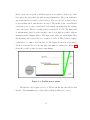
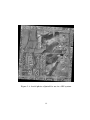
What is PRISM? PRISM stands for Polar Radar for Ice Sheet Measurements [20].
The goal of the prism project is to measure the thickness and other characteristics
of ice sheets using radar. A synthetic aperture radar (SAR) will be used to gather
as detailed information about the bottom of the ice sheet and determine if ice is
frozen to the bedrock or if there is water at the bedrock. A bistatic SAR utilizes
two set of radar equipment one to send and the other to receive. During the
process one antenna aims at a fixed location while the other moves around. The
second antenna system moves in a pattern to collect a wide area of signals about
target, thus creating many data points for a single target, acting like increasing
the antenna size. This allows for an antenna as big as needed. The tradeoff is
that it takes longer to achieve detailed data about a single point.
2
Polar regions, like Antarctica and Greenland, are quite cold with temperatures below zero during the summer. Measuring the ice, especially using a SAR, is
tedious process. Difficulties with such situations it becomes apparent that having
a robot that will not care about the weather and is willing to work so long as
it is fueled, becomes quite useful. This was the motivation for constructing a
robot that can survive the cold and snow. Henceforth the robot shall be known
as MARVIN, or Mobile Arctic Robotic Vehicle with Intelligent Navigation.
1.3
Approach
Design and construction of the UGV is divided into four phases: platform
assessment, actuation, winterization, and testing (local and polar). Possible base
platforms range from RC cars to custom-built robots. In the first phase a number
of factors will be weighed to determine the viability of the vehicle to perform the
job of being a mobile SAR. Several platforms are judged on past experiences and
ability to handle the harsh conditions. The second phase involves converting the
vehicle into a computer controlled UGV. The tests done in this phase determine
what needs to be done to automate and winterize the vehicle. Winterization is
tested by applying water to the seals, placing equipment into an environmental
chamber, and finally in real arctic weather. The control software is tested on
how accurately the vehicle can approach a waypoint in the snow. The final phase
involves field testing the rover in a variety of conditions. The vehicle is tested in
Kansas to see how well everything stands up to warm weather and punishment at
an ATV park. The final test is to see how the UGV stands up to the environmental
conditions on Greenland’s ice sheet.
3
1.4
Thesis Organization
This thesis is organized into eight chapters. Chapter 1 is the introduction. Vehicle
selection follows as chapter 2. Chapter 3 pertains to the steps taken to actuate
the driving of the vehicle. Chapter 4 examines the various methods of weather
proofing vehicles. Chapter 5 discusses the control software. Chapter 6 presents
the steps chosen and an overview of the construction of MARVIN. The results
and analysis of field tests are presented in chapter 7. And finally chapter 8 ends
with the conclusions and future results.
4
2. Mobile Base Selection
This chapter explores the different possible base platforms for creating a UGV
for polar environments. The first step to selecting the proper vehicle is to start
by looking at the requirements need to perform the given task. Then, individual
vehicles types and robotic platforms are analyzed. The analysis includes the
satisfaction of the requirements and what will be required to fix any failings in
requirements. Finally other projects related to converting vehicles into UGVs will
be examined.
2.1
Requirements
The first requirement of the mobile platform is the ability to drive on snow and
ice without slipping or getting stuck, while carrying maximum load of 300kg. It
must operate in a temperature range of -30C to 40C and altitudes from 0m to
3000m above sea level. Not only should the vehicle drive on snow and ice, but it
should also handle dirt and grass, as much of the testing is performed in Kansas.
Minor modifications between running in each environment, such as changing the
engine’s carburetor’s jets are acceptable, but major changes, like changing ski to
tires or vice versa, are less desirable.
In addition to working in a wide range of temperatures and altitudes,
the base platform must be able to carry the maximum load of equipment,
measured by both weight, 300 kg and volume, 40U’s of rack mount space. The
equipment onboard includes the radar system, automation controls, power system,
communication equipment, and a weather covering. At times the vehicle may need
to carry a human operator as well. The platform must also be capable of towing
a large 2m by 4m antenna array that weighs up to 150kg. The radar antenna
5
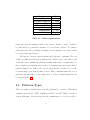
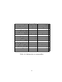
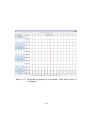
Requirement
Value
Towing Capacity
150kg
Payload Capacity
200kg
Rack Mount Space
40U
Turning Radius
5m
Altitude 0 - 3000m
Temperature -30 - 40C
Range 60km/day
Table 2.1: Vehicle requirements.
brings into play the turning radius of the vehicle. With too large a radius it
becomes harder to position the antenna or to avoid some obstacles. Too small a
radius introduces the possibility of running over the antenna, but could possibly
be corrected through software.
The last set of factors comes from time and budgetary constraints. The cost
of the base platform involves more than just the ”sticker” price of the vehicle, but
additional costs to making the platform working in the range of temperatures. A
more complex base platform will cost more to maintain, fix, and actuate than a
relatively simple base. Time is also a factor, given that the rover had to be on the
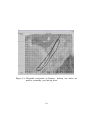
ice in less than a year from the time received. Time constraints make the ease of
platform conversion into a rover a higher factor. A list of formal parameters can
be found in Table 2.1.
2.2
Platform Types
There are many potential types of mobile platforms to consider. This thesis
examines snowmobiles, ATVs, Amphibious ATVs, and RC Tanks, as well as
custom platforms. Specifications from the manufacturer of each base will be
6
compared to the requirements.
Sometimes the standard model of the base
platform does not meet all the basic needs, but add-ons or optional modifications
to increase their capabilities are available. These add-ons usually change the type
of environment the vehicle can operate in, like changing the skis on a snowmobile
to wheels.
2.2.1
Snowmobiles
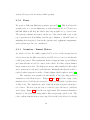
Snowmobiles design specifically tailors them to handle ice and snow. They cruise
through snow and ice and are one of the main types of vehicles used at polar
base camps. The drawback to snowmobile it that they do not work well on dirt
and grass. Replacing the skis with wheels will correct this problem and allow
snowmobiles to drive in the not so snow friendly Kansas. In addition snowmobiles
generate noise which can interfere with radar operations.
2.2.1.1
Vehicles
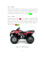
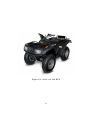
Snowmobiles are typically divided into two categories, those designed for racing
(Figure 2.1) and those that perform work (Figure 2.2. The racing snowmobiles
have higher top speeds, and better turning radius. However, the work snowmobiles
have more room for equipment and supplies. For building the UGV, speed is not
as great of a factor as having space for automation equipment, but the turning
radius, about six meters, is important for control and obstacle avoidance [35, 5, 56].
2.2.1.2
Conversion Kit
A conversion kit (shown in Figure 2.3) can be used to convert a snowmobile to
working on grass and dirt. These kits still use the track drive as the main source
of power for the snowmobile, changing the front skis to wheels. This has the effect
of going from skis to roller skates [49].
7
Figure 2.1: Arctic Cat F5 performance snowmobile.
Figure 2.2: Arctic Cat Bearcat Widetrack touring snowmobile.
8
Figure 2.3: Ski to wheel conversion kit for snowmobiles.
2.2.1.3
UGV Snowmobiles
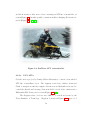
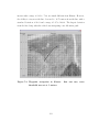
Very few projects have been done to automate a snowmobile. In 1997, NASA
had plans to search for meteorites in Antarctica using multiple robots. The plan
included the possible use of snowmobiles as the platform as well as a previously
deployed robot named Nomad. A vision of the system can be seen in Figure 2.4.
[24]
In 1999, the Universita degli Studi di Siena in Italy, built an UGV from a
snowmobile. The snowmobile’s track drive was replaced with a differential drive
system. The changes to the drive were made to simplify the control, giving “the
possibility of changing direction with ease and of steering in a very limited space”
and for a larger surface footprint. The goal of the robot was to find meteorites
beneath the ice in Antarctica [53].
9
Figure 2.4: Vision of robotic snowmobile system.
10
2.2.2
ATVs
All Terrain Vehicles (ATVs) provide enough of horsepower for most applications
and work in most terrains. Most 4-wheeled ATVs are fairly inexpensive. The
possibility of an electric ATV is also examined. Typically ATVs have a top speed
over 40 km/h and a turning radius of about five meters [55, 6, 16].
2.2.2.1
Vehicles
The Yamaha Big Bear (Figure 2.5) is a good example of a utility ATV. Utility
ATVs are designed as workhorses. They are meant to tow equipment and handle
rough terrain. Unlike sports models, they use their horsepower for towing and
traction instead of speed. The Arctic Cat 500 BTX is another example of a
utility ATV (Figure 2.6) [55, 6].
Figure 2.5: Yamaha Big Bear.
11
Figure 2.6: Arctic Cat 500 BTX.
12
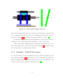
The Gorilla, an electric ATV, reduces the need for fuel and oil and greatly
reduces cost of maintenance. Electric power allows for use of alternative power
sources, like solar and wind. However, conventional rechargeable batteries do not
do well in cold temperatures, the vehicle itself may have problems with the cold
weather. The Gorilla is shown in Figure 2.7 [16].
Figure 2.7: Gorilla Electric ATV.
2.2.2.2
Winterization
ATVs perform well in dusty and dessert terrain, but unless modified, they have
problems dealing with the cold and ice. The undercarriage of an ATV is exposed
to blowing snow and ice. Ice will eventually cause damage to gears, wheels, and
other exposed parts. The surface area from the tires can push the ATV into soft
snow causing it to get stuck more often. The undercarriage can be covered to
protect the ATV and a snow conversion kit can convert the rear tires to treads
13
and the front tires to skis, more or less converting an ATV into a snowmobile, as
seen in Figure 2.8. Another possible conversion includes changing all four tires to
treads (Figure 2.9) [40, 23].
Figure 2.8: SnoTraxx ATV conversion kit.
2.2.2.3
UGV ATVs
CyberScout is a project by Carnige Mellon University to convert a four wheeled
ATV into a surveillance rover. The designers created two vehicles, Lewis and
Clark, to navigate around the campus. Servomotors and hydraulics were used to
control the throttle and steering. Sensors included a total of five cameras and a
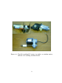
Differential GPS. Lewis can be seen in Figure 2.10 [48].
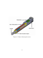
The Gryphon series of robots were built to do search and rescue by the
Tokyo Institute of Technology. Gryphon I, shown in Figure 2.11, uses a 6.1
14
Figure 2.9: LiteFoot ATV track conversion.
15
Figure 2.10: CMU’s Lewis from the CyberScout project.
16
KW generator and a 500 W alternator for power and was remote controlled,
not autonomous. Gryphon II expands to allow for a human pilot requiring “a
special Hybrid Actuation System”. Finally a heavy version, Gryphon III (Figure
2.12), was constructed to handle winching capabilities as well as more sensors and
a field arm. [46]
Figure 2.11: Gryphon I internals.
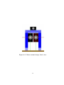
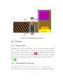
2.2.3
Amphibious ATVs
Amphibious ATVs’ design allows them to not only go over dirt and climb steep
hills, but also float. Floating, while not a requirement, provides a waterproof,
and thus snow-proof, bottom. Protecting the gears, engine, and other equipment
from snow and ice is required. Most of the amphibious ATVs drive by a method
17
Figure 2.12: Gryphon III with field arm.
18
of skid-steering. Skid-steering involves two brakes and a throttle and allows for a
tight turning radius, not quite in place, but very close to it.
2.2.3.1
Vehicles
Recreatives Industries makes a line of amphibious ATVs that use six wheels and
drive using skid-steering. The MaxATV line comes in three different versions, a
small two-seater, a four person model, and finally a truck like model. Any of these
models can be fitted with tracks to help them travel across the snow. Recreational
Vehicles also makes a weatherproofing kit [33].
Figure 2.13: Recreatives Industriess’ MaxATV.
Argo provides a range of amphibious vehicles that use from six to eight
wheels. All these vehicles use a skid-steering drive. Argo provides a track kit for
19
their vehicles. However, they do not provide directly weather proofing kits, but
vendors provide weatherproof shells [7].
Figure 2.14: Agro Bigfoot.
2.2.3.2
UGV Amphibious ATVs
Funded by the Department of Defense, the Gecko is an automated Argo Bigfoot
designed for reconnaissance and surveillance.
The amphibious nature of the
vehicle allows the Gecko to scout across creeks and rivers without the need to
place human soldiers in harms way [50].
The Predator, converted from a Predator ATV, performs semi-autonomous
farming. Some of its goals are given to it by a human, but for the most part the
vehicle drives and navigates on its own through the fields spraying chemicals and
20
Figure 2.15: GECKO UGV.
21
planting seed. The semi-autonomous nature of the vehicle fits well with the plans
for the PRISM project as scientists will want to tell the rover to go to certain
positions and to get there safely. Predator uses a system of cameras, gyros, and
differential GPS to navigate, and model airplane servo motors to steer [17].
Figure 2.16: Autonomous Solutions’s Predator.
2.2.4
Remote Controlled Tanks
A remote controlled tank provides a simple electric platform already complete
with a way to control it. The AAVP7A model is an amphibious model, which
will make weatherproofing easy. The RC tanks are usually made to 1:8 scale,
which is a little too small for the kind of equipment and power needed for the
PRISM project. However, a custom 1:4 or 1:2 scale model can be made to order.
The downside to ordering a custom model is that it will take significant time
22
before it arrives. Since an RC tank at the scale needed has never been built,
the specifications are not known. Without specifications is cannot be determined
whether the RC tank will meet all of the given requirements [4].
Figure 2.17: AAVP7A Amphibious RC Tank
2.2.5
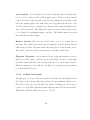
Customized Vehicles
Customized vehicle refers to starting from scratch and designing the UGV from
the ground up.
A custom built vehicle provides the flexibility to build any
vehicle necessary to complete the job. However, custom jobs require much more
expertise and time to build and, arguably, are more expertise. Custom jobs tend
to provide the greatest successes as well as the greatest failures. In building a
UGV from scratch all of the design constraints must be taken into consideration
and accommodated.
23
2.2.5.1
Nomad
Nomad is a robot built by CMU to find meteorites in Antarctica. Nomad has
a unique collapsible chassis that allows it to fold up to be shipped. Nomad has
already proven itself useful for the exploration of arctic environments. Nomad
was also tested in a desert environment, demonstrating that robots can be built
to handle a wide variety of weather. Nomad, being a tested and proven vehicle,
gives valuable information on what works and what does not work for robotics in
arctic environments. Nomad included a variety of sensors, including GPS, laser
range finders, and video cameras [34].
Figure 2.18: CMU’s Nomad.
24
2.2.5.2
Dante
Dante I and II, built by CMU, are legged robots designed to climb into a volcano.
A walking robot has the distinct advantage of being able to maneuver over more
types of terrain, than a robot based on wheeled locomotion. This advantage,
however, is not much of an advantage when the terrain is endless snow and ice.
A legged robot would need to have “snow shoes”. That is the pressure from a leg
would need to be distributed across fresh snow to prevent the robot from sinking
beneath the surface of the snow. A walking robot would provide an easy way
to stop and position the radar, since the mobility would not be as limiting as
wheeled power vehicles. They are also typically slower than wheels, but speed is
not as great of a factor as getting the alignment of the radar. Dante used a laser
range finder and array of cameras to help it navigate and map out the inside of
volcanoes [10].
2.2.5.3
Mars Rover
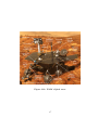
NASA’s Spirit rover is another example of a custom robot designed for a specific
task. In this case, the rover explores Mars. The rover uses a six-wheeled drive
system. The drive system allows for great flexibility for going over rocks and
bumps, keeping the robot stable.
Figure 2.20 shows a picture of the Mars
Pathfinder [25].
25
Figure 2.19: CMU’s Dante II.
26
Figure 2.20: NASA’s Spirit rover.
27
2.3
Base Selection
Final choice of the mobile base platform was made after looking at all of the
details of the vehicles, reading user reviews, viewing records of each vehicle in use,
and finally examining and test driving vehicles.
Tables 2.2 to 2.5 show a description of all of the mobile base vehicle types
considered for automation as part of this thesis.
28
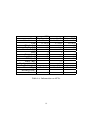
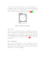
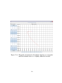
Snowmobiles
Name
VK 540 lll Pantera 800 EFI
Manufacturer
Yamaha
Arctic Cat
Cost
$7,699.00
$7,999.00
Wieght (kg)
292
271
Towing (kg)
Max Load (kg)
Tires
Track+Ski
Track+Ski
Height (cm)
135
Length (cm)
312
338
Width(cm)
135
122
Power (HP)
140
Top Speed (km/h)
Turning Radius (cm)
Control Type
Handle Bar
Handle Bar
Weather Proof ?
Y
Y
Electric?
N
N
Table 2.2: Information on snowmobiles.
29
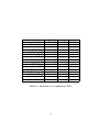
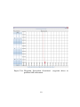
ATV
Name Big Bear 4x4
Gorilla 500 4x4 TBX
Manufacturer
Yamaha Gorilla Vehicles
Arctic Cat
Cost
$5,199.00
$5,500.00
$6,100.00
Wieght (kg)
253
250
335
Towing (kg)
411
1800
477
Max Load (kg)
120
270
181
Tires
4
4
4
Height (cm)
117
99
122
Length (cm)
201
178
244
Width(cm)
111
88
118
Power (HP)
5.5
Top Speed (km/h)
40.3
Turning Radius (cm)
518.16
Control Type
Handle Bar
Handle Bar
Handle Bar
Weather Proof ?
Electric?
N
Y
N
Table 2.3: Information on ATVs.
30
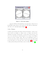
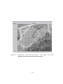
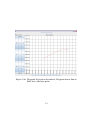
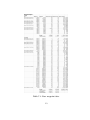
Name
Manufacturer
Cost
Wieght (kg)
Towing (kg)
Max Load (kg)
Tires
Height (cm)
Length (cm)
Width(cm)
Power (HP)
Top Speed (km/h)
Turning Radius (cm)
Control Type
Weather Proof ?
Electric?
Amphibious
Max IV
Buffalo
BigFoot
R.I.
R.I.
Argo
$8,030.00 $12,030.00
$8,000.00
351
408
414
454
454
654
363
408
327
6
6
6
107
132
244
251
147
147
16
20
18
32.3
32.3
39.0
In Place
In Place
In Place
Two Sticks Two Sticks Two Sticks
Y
Y
Y
N
N
N
Table 2.4: Information on amphibious ATVs.
31
Tanks
Robots
Name AAVP7A (1:4)
Nomad
Dante
Manufacturer
Interdacom
CMU
CMU
Cost
$10,000.00 $1,600,000.00
Expensive
Wieght (kg)
208
Towing (kg)
Max Load (kg)
Tires
Track
4
8 Legs
Height (cm)
76
Length (cm)
198
240
Width(cm)
82
240
Power (HP)
Top Speed (km/h)
Turning Radius (cm)
In Place
In Place
In Place
Control Type
Radio Remote/Auto Remote/Auto
Weather Proof ?
Y
Y
Electric?
Y
Y
Table 2.5: Information on tanks and robots.
32
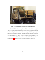
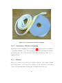
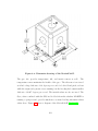
Figure 2.21: The original Buffalo, prior to modifications.
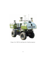
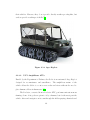
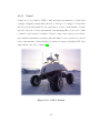
The MaxATV Buffalo, an amphibious ATV, was selected for the project.
This choice resulted from a number of factors. The specifications showed that the
Buffalo would perform the tasks needed. A vender provided the opportunity to
test drive and examine the internals. After inspecting the vehicle it became quite
clear, that its simple, yet durable, design would prove easy to automate, as well
as easy to maintain. The Buffalo was also ordered with the full weather kit and
tracks. Figure 2.21 shows the vehicle as obtained with no modifications.
33
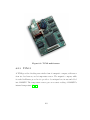
3. Actuation
After selecting MaxATV’s Buffalo amphibious ATV, it was time to further analyze
the vehicle and choose a method of converting it to a UGV. The Buffalo, a skidsteering vehicle, is controlled by two brakes and a throttle. The throttle controls
overall speed while each brake causes half of the vehicle to stop, allowing it to
make tight turns. Actuating this type of control system involves placing motors
on the throttle and each of the brakes. However there is the questions of what
motors to use and how to mount them.
3.1
Requirements
The question of actuation is not just a question of motors, but how to control
those motors, and the ability of all components to satisfy the given constraints
of the system as a whole. The system as a whole comprises of motors, motor
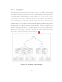
controllers, power supplies, and software to run the system. Figure 3.1 shows the
drive system for the vehicle.
The first requirement of the motors is the amount of force that will be
required by the motors to perform their task. This is the most important factor,
as too little force in the motors will lead to control issues that cannot be solved
by software. The motors must also be able to survive the cold weather and be
water resistant. As a safety requirement if there is to be failure in the system the
vehicle should come to a sudden stop. Also in the event of failure of a motor,
the vehicle should come to a stop. This means the motors must be monitored
and in the case of the throttle motor must disengage on failure. This means that
it the state of the motors should be known, that is whether they are on and
what position they are in. From a control point of view, some degree of position
34
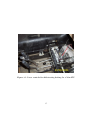
Figure 3.1: Lever controls for skid-steering driving for a MaxATV.
35
resolution is necessary. However, current design requires only two positions for the
lever motors: braking and free. The throttle motor, on the other hand, requires
a higher level of resolution, as speed control is more important. Added to this
requirement is the ability for a human override on the vehicle. A human override
provides the ability to complete the task in case of failure of the control system.
In arctic environments it may not be possible to replace parts, but it is possible
to assign a human the task of driving the vehicle
3.2
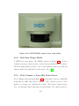
Measurements
The first factor to selecting a motor is the amount of force needed.
Force
measurements are highly important when selecting motors for actuation of the
vehicle. To measure the forces required to move the throttle and brake levers, a
digital force meter (Figure 3.2 is used to find the exact measurements. The force
meter has 0.445 N (0.1 lbf) resolution and can be mounted to a secured location,
eliminating human error of pulling on the force meter. In all cases, distance was
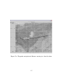
only measured by the furthest point back needed to engage a full brake [54].
Figure 3.2: Force Five force measuring tool
The measurements on the levers were done at three different locations. The
36
first location, the low point, would hide any show of actuation, at the base of the
lever where the levers meet the skid steering transmission. The point eliminates
any rotational forces caused by lever motion. The force needed at this location
is greater than 448 N, and therefore not used. The middle point, even with the
seat in the rover, is easy to attach motors by simply extending from the existing
seat to the levers. The force at this point is a reasonable 155.7 N. The final point
of measurement, just below the throttle control, is as high as possible without
interfering with a human driver. The high point, while not much higher then
the medium point, reduces the force required to 111.2 N. This location requires
a platform to be built to hold the motors. The higher the motors are mounted,
the more rotational forces come into play, and must be adjusted for. Figure 3.3
shows the possible points of actuator attachment.
Figure 3.3: Posible motor points.
The throttle cable required a force of 15N for full throttle and 10N for half
throttle. The maximum speed of the vehicle will most likely not be used.
37
3.3
Motors
Different types of motors require different methods of attaching the motors to the
control system of the vehicle. In this project, the differences of mechanical versus
electromagnetic and linear versus angular were studied.
3.3.1
Mechanical vs. Electromagnetic
Mechanical motors, by definition, use electricity to drive gearing systems. Figure
3.4 shows the various sizes and gearing that are available with mechanical motors.
This type of motor has been around for some time and provides a good amount
of force. The mechanical motors can be adjusted to give more force using gears,
pulleys, or other methods. Mechanical gears do have a downside: given enough
moisture and cold, they will freeze, lock up, and break the gears or burn out.
The term electromagnetic motor refers to motors that do not use gears to
achieve their motion. They are prismatic motors, using electromagnets to move an
object with very little friction. The biggest drawback to these motors is that they
require significant power to work and hold their position. Power failure causes the
motors to no longer hold and the vehicle will come to a stop. The lack of resistance
without power makes switching to a human driver just a flip of a switch. The use
of large power is a concern. The largest available from Linmot requires a peak of
2A at 72V (150W), which is a lot of power when multiplied by three motors. A
cutaway of the linear motor is shown in Figure 3.5 [22, 21].
38
Figure 3.4: Top left: medium DC motor, top right: car window motor,
bottom: AC washing machine motor.
39
Figure 3.5: Linmot eletromagnetic motor.
40
3.3.2
Linear versus Angular
The direction in which a motor puts its force is also important to consider. Angular
force motors provide the force in a circular or angular motion. This motion is
useful for the conversion because levers when pulled back move in an arc from the
attachment point. Angular motion can also be converted to linear motion by using
a cable that pulls on a line, similar to a winch. Angular force would be better
placed at the attachment point of the lever, but this would also require a strong
motor. The best method in this application is to use a winch cable attachment to
connect to the levers.
Linear motors apply forces in a linear motion. This is typically done with a
worm gearing system or with a cable and pulley system. This motion provides a
direct method of moving the lever. The downside is that the lever’s motion causes
rotational forces which act against the linear motors producing extra stress and
reducing their mean time to failure. This can be overcome by adding a rotational
joint to the motors so that they move with the rotational force instead of having
it act against them.
3.3.3
Comparison
Tables 3.1-3.3 shows a list of motors evaluated by their ability to fulfill the
discussed requirements [22, 15].
3.4
Motor Control
In addition to having the proper strength of motor for the job, controlling the
motors is also important. Eventually, to achieve remote control, the motor controls
will have to be through communication to a networked computer. They will also
need position feedback. For the brake levers, the position sensors do not need to
41
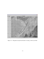
Linmot
www.linmot.com
Part Name P01-23x80
P01-23x160
Part #
30x90 24V
48V
70x210 24V
48V
72V
Reseller (URL)
Cost
Min Units
Unit Cost
Power (W)
48
144
24
96 201.6
Weight(kg)
0.383 0.383
0.562 0.562 0.562
Speed (cm/s)
190
340
130
300
400
Peak Force(N)
21.79 32.91
21.79 44.03 60.05
Limit Force (N)
13.78 20.90
12.89 24.90 35.14
Min Stroke (mm)
30
30
70
70
70
Max Stroke (mm)
90
90
210
210
210
Accuracy (mm)
0.1
0.1
0.1
0.1
0.1
Length (cm)
17.7 17.7
25.7 25.7 25.7
Width (cm)
4
4
4
4
4
Height (cm)
3.5
3.5
3.5
3.5
3.5
Duty Cycle (%)
50
50
50
50
50
Table 3.1: Linmot inear actuators.
42
Linmot
www.linmot.com
Part Name
37x120
37x240
Part # 20x100 24V
48V
72V 60x260 48V
72V
Reseller (URL)
Cost
$1,300
Min Units
1
Unit Cost
$1,300
Power (W)
72
144
432
144
360
Weight(kg)
1.200 1.200 1.200
2.214 2.214
Speed (cm/s)
140
260
400
130
220
Peak Force(N)
60.93 60.93 121.87
120.09 204.16
Limit Force (N)
40.92 40.92 81.84
72.05 119.21
Min Stroke (mm)
20
20
20
60
60
Max Stroke (mm)
120
120
120
260
260
Accuracy (mm)
0.1
0.1
0.1
0.1
0.1
Length (cm)
22.7 22.7
22.7
34.7
34.7
Width (cm)
5
5
5
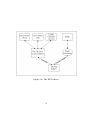
5
5
Height (cm)
5
5
5
5
5
Duty Cycle (%)
50
50
50
50
50
Table 3.2: Linmot inear actuators.
43
Danaher
www.danahermcg.com
Part Name Electrak 1 Electrak 2 E050 E150
Part #
SP1
D12 DE12 DF12
Reseller (URL)
Cost
Min Units
Unit Cost
Power (W)
67.2
240
45.6
156
Weight(kg)
0.659
4.873
2.477
Speed (cm/s)
1.778
2.54 1.8288
5.08
Peak Force(N)
333.6
1112 266.88 2001.6
Limit Force (N)
333.6
1112 266.88 2001.6
Min Stroke (mm)
0
0
0
0
Max Stroke (mm)
152.4
203.2 152.4 152.4
Accuracy (mm)
Length (cm)
16
36
27.3
31.8
Width (cm)
4
7.6
5.3
9.8
Height (cm)
7.3
14.7
10.3
19.4
Duty Cycle (%)
25
25
25
25
Table 3.3: Danaher linear actuators.
44
be more than a couple of switches to determine if the lever is in or out. This may
limit flexibility, but should not hurt performance. Throttle, on the other hand,
requires a much finer resolution of control, requiring a more accurate position
feedback. In either case, it is clear that a microcontroller is needed to control
the motors as well as feedback sensors. The microcontroller will also need to
communicate to an on board computer.
3.4.1
Microcontroller
Some motor manufacturers also make controllers for their motors. This makes the
task of wiring and writing software for the microcontroller a done task. In either
case of buying a controller-motor set or a microcontroller, software to control the
system is still needed. Likewise, since this goal of the project is to expand to being
fully autonomous, the control hardware will need to take this into account.
3.4.2
Computer
To be fully autonomous, the system requires much more computing power than
a standard microcontroller can provide. To handle the needed processing power,
a ruggedized computer will be used to control the motor controller as well as the
sensors. A computer also provides all the necessary capabilities to complete the
remote control requirement through 802.11bwireless connection. Using a computer
instead of an embedded system also provides the ability to switch out the computer
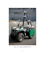
in the field or make software correction directly to the machine. The computer
could be either a rack mount system or a laptop. A laptop provides easy access
and has uses other than those in the field. Whereas a rack mount system would
have a more stable mount within the vehicle.
45
4. Winterization
Since the rover must operate in arctic environments steps must be taken to
ensure the safety of the onboard equipment. The body of the vehicle must be
able to protect the equipment that is not designed for use in cold temperatures.
Additionally the engine must be modified to handle the cold weather and the
altitude.
4.1
Protective Shell
A protective shell is needed to protect the SAR radar and any other equipment
inside the vehicle. The shell should be able to withstand winds of at least 60kph
with blowing snow. In addition to keeping out the snow and cold, the shell should
also be able to vent heat generated from the engine and computer equipment. It
must also be able to house a human operator comfortly without being so heavy
that the vehicle would sink into the snow.
4.1.1
Standard Additions
The Buffalo MaxATV comes with a wind shield, a roll bar, and a protective cover.
The default covering does not cover the back area where the equipment will go nor
does it provide much protection from severe weather, especially if stored outdoors.
The manufacture’s winter package does not lend itself well to modification either,
so other options must be considered.
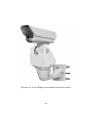
46
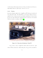
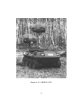
Figure 4.1: Scale carbon fiber shell.
4.1.2
Carbon Fiber
Carbon fiber is a plastic used in airplanes, models, and various other applications.
It is lightweight and strong and can be molded into the exact form needed. It is
still a plastic, so it becomes brittle at extremely cold temperatures. The design of
the mold must incorporate any future additions such as doors and holes for wires.
Without knowing exactly what equipment will be installed for automation, SAR,
or other test applications, this is problematic. A model mock up shell is shown in
Figure 4.1.
47
4.1.3
Metal
A metal shell welded to the base vehicle will make a strong structure. Metal can
be drilled into and extra pieces can be welded on later if necessary. However, the
weight and density of iron will cause the vehicle to be too heavy, and welding
lighter metals such as aluminum and titanium require extensive expertise, and
could be very costly.
4.1.4
T-slotted Extrusions
T-slotted extrusions, made of aluminum, provide a lightweight modular solution
that allows components to be added later. The extrusions are connected by bolts,
which can rattle loose over time. In addition, a frame will need to be reinforced
with cross beams to minimize flex. T-slotted extrusions only create a frame; holes
in the frame will need to be filled in with other materials.
4.2
Sealing
No matter what type of shell is used, there will always be gaps in the structure.
Gaps come from drilling through the shell for doors, vents, and wires. These holes
need to be filled in to insure that no blowing snow gets into the vehicle. However,
not all of the holes need be air tight, as the engine and on-board equipment will
need to vent out generated heat.
4.2.1
Rubber
Rubber strips can be used to cover larger gaps of two to three inches. Larger gaps
occur mostly where doors come together or where the edge of the shell does not
exactly fit the vehicle. The seals must be bolted on, and will still leave behind
some small gaps that require a different solution.
48
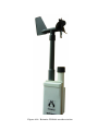
Figure 4.2: Automotive weather stripping.
4.2.2
Automotive Weather Stripping
Automotive weather stripping, as seen in Figure 4.2, requires pressure to maintain
to form and maintain a seal. The stripping is applied by removing the backing
and pressing into place. It is useful for areas that lock and seal, like doors or
equipment holes.
4.2.3
Silicone
Silicone gel comes in a tube and can be applied anywhere on the vehicle. It fills
in holes and hard to reach areas. Upon application, the gel should be smoothed
down to prevent lumps that can snag and eventually remove the seal.
49
4.2.4
Quick Weld
Quick weld, like J.B. Weld or metal epoxy, bonds to metal. It does not hold as
well as a true weld, but is quicker to apply, easier to transport, and can get into
the cracks of the metal. Quick weld does not bond well to smooth surfaces.
4.2.5
Air Filters
Air filters block dust particles and snow. The air filters will let oxygen into
the vehicle and removing heat while keeping out the snow. Most air filters are
prepackaged and a variety of filters are available. Using air filters requires a way
of attaching them to the vehicle. Tape or bolting slide rails could be necessary.
4.3
Engine Adjustments
Both the vehicle engine and the onboard generator will need to be modified to
handle the cold weather and reduced availability of oxygen at higher altitudes.
In addition, the generator must be able to vent exhaust, especially if there is a
human occupant.
4.3.1
Generator Exhaust
The generator exhaust needs to be vented to the outside. If the generator is in a
different compartment from the main engine it would require building a dedicated
exhaust pipe.
4.3.2
Re-Jetting
Both engines will need to be re-jetted. Re-jetting the carburetor allows more
oxygen flow in with the gas and causes the proper mixture. With too much oxygen,
50
the gas will burn rich causing soot to appear on the spark plug, eventually causing
them to not work. With too little oxygen the gas will not explode and the engine
will flood. In either case, the vehicle would not function. Since the vehicle must
run at both sea level and 3000 meters above sea level, different jets will be needed
for each location.
4.3.3
Oil
Oil prevents the wear and tear on the pistons of the engine. It must be able to
flow properly in the cold, or the piston will get sticky and have to work harder.
For both engines, the oil should be changed to low-temperature oil before leaving
and replaced with warm weather oil upon returning. In either location, synthetic
oil should be used, as it has a longer lifetime.
4.3.4
Engine Weather Kit
The Kohler engine in the Buffalo has a winter weather kit. The kit takes the heat
from the exhaust and transfers it to the incoming air. The heat transfer melts the
snow and keeps the engine warm and oil flowing. The air filter is also enlarged
to filter out any stray snow particles. Unfortunately, the kit does not fit on the
engine while in the Buffalo.
51
5. Software
In addition to hardware design the rover requires software co-design. The software
design should be portable and robust, and should allow for remote sensing and
control. In terms of portability, the code should run on any operating system and
be flexible enough to control and understand a variety of sensors and actuators.
It is also important in field robotics to test in a controlled environment. If a
system design allows for porting to an indoor robot, and actuator control through
simulated sensors, many faults can ve detected and fixed.
5.1
Background
A number of research efforts have worked on software designs for controlling
robots. JAUS, Joint Architecture for Unmanned Systems, spearheaded by the
Department of Defense seeks to cover all possible control systems needed for
vehicles. This includes Uninhabited Air Vehicles (UAVs), Uninhabited Ground
Vehicles (UGVs), Uninhabited Underwater Vehicles (UUVs), and the like. JAUS
uses a hierarchy involving four levels: system, subsystem, node, and component.
The levels represent the distance from the hardware with the component level
sitting just above the actual hardware. The node level covers redundancies and
hides all of the hardware level details. Subsystems represent an individual part
that controls nodes. Examples include any single uninhabited system or any
operator system. The system level can be seen as the planner that controls the
subsystems to achieve a higher goal [51].
The University of Florida created a system that could be moved from one
platform to another without modification. “The architecture consists of a Mobility
Control Unit (MCU), Path Planner (PLN), Position System (POS), Detection and
52
Mapping System (DMS), and a Primitive Driver (PD).” The system formed the
beginnings of the ideas behind JAUS. [8]
Autonomous Solutions has a software system called Mobius. Mobius is used
to control a wide variety of vehicles. It allows for viewing through cameras, a
waypoint mode, and a joystick controlled mode. This software has been used to
control military surveillance vehicles, agriculture equipment, and even an RC car.
Mobius is also compatible with JAUS [17].
In industrial robotics, an API call PINROB (Portable api for INdustrial
ROBots), also seeks to unify robotics, but on a much more focused level. PINROB
has fewer levels and is concentrated on robot manipulators like those used in a
factory. [18]
Ultimately all control systems, including robotics, can be expressed as a
function of the sensors giving an output of what the actuator values should be.
To differentiate from the JAUS, the software for this project is designed in a
object-oriented hierarchical fashion. Like JAUS, each component of the software
is independent, but can combine to create synergetic effects. A navigation system
could be developed by combining position, heading, and a way of moving. The
way of moving should be independent of the navigation system, how the heading
is gotten or how the position is obtained. The position could come from using
GPS, Global Positioning System, dead reckoning, or some method combining the
two for higher resolution.
Robotics also requires some level of real-time operation. Certain operations
need to perform in a given amount of time, called real-time constraints. These
constraints exist for safety and are used in situations such as aircraft stability and
operation of nuclear submarines. For the rover, the real-time constraints can be
relaxed given the operating environment, flat polar ice regions with little to no
human population. However it is still critical to avoid obstacles and ensure the
health of the rover while in these regions.
53
The combination of real-time constraints plus the object-oriented nature
of the software led to the development of the control software for the rover in
Java. Utilizing KURT Linux, and using the RTJ, Real Time Java, it is possible
for Java to have nanosecond resolution [36, 1]. Java also provides extensions for
remote access and control, known as remote method invocation, or RMI. RMI
will allow remote operation of the rover as well as the ability to view the sensor
data from afar. Of course, there will be times where Java alone is not enough.
In these instances C functions can be called from Java using the Java Native
Interface (JNI). Java can also utilize higher level logic languages. KAWA is a
scheme interpreter for Java and JESS is a ruled based system similar to CLIPS.
There are also various Prolog implementations in Java. All of these features are
in addition to the robust and object-orientated nature of Java.
5.2
Design
The best design would have the software mimic the function of the hardware,
using a hardware abstraction layer to allow for the independence of the code.
With hardware abstraction, portability and simulation become attainable goals.
However, this still requires writing wrapper code, or device drivers, for any used
equipment. The overall design is that robots are composed of devices that contain
sensors, actuators, various parameters, and a way of communicating to them. The
sensors and actuators are then combined to form system. Systems combine with
other sensors and systems to form more complex behaviors. This API design is
shown in Figure 5.1.
5.2.1
Device
Every piece of equipment can be seen as a Device. A Device is an upper level
class that represents a real piece of equipment that can be computer controlled
54
Figure 5.1: API design structure.
55
or programmed. A Device has a way of communicating to the physical device, a
set of parameters, a set of sensors and a set of actuators. It is not necessary for
a device to have both sensors and actuators. An example of a device would be
the Nomadic Scout robot, which can be communicated to via serial port, has a
variety of sensors, and a motor control system. Likewise a simple compass can
be considered a device, since it has a communication, serial port, and provides
heading sensor information [27, 28].
Communication is any way of getting input to or output from a device.
This can be serial (RS232, USB, RS422, etc.), Ethernet, radio, or any other way
of sending and receiving data from a device. For example, a microcontroller can
be programmed using an RS232 connection, and a Web camera’s image can be
obtained from the Internet using the HTTP protocol. Communication is not
limited to the physical but can also tie into operations of the host machine. Files
can be considered a form of communication since they can be written to and read
from.
Parameters of a device include any feature that rarely changes over the
operation of the device. The serial port to which the device is connected to
is a parameter. Likewise, an IP address, updates rates, and filenames can be
considered parameters of a device.
A sensor gathers data from the real world. An actuator causes changes to
the real world. A device can have any number of sensors or actuators. As sensors
and actuators change the most, they will be the focus of development.
5.2.2
Abstract Sensor
As previously stated, a sensor gathers data from the real world. This could be
a sonar sensor, a camera, or even a push-button. All sensors gather data and
therefore in code should represent that data. In the highest level, any sensor
has a certain number of dimensions and each dimension of sensor has a number of
56
values. For example, an image would have two dimensions x and y, and number of
values per each dimension, like the pixel values of the image. Similarly, a weather
station would have many dimensions: temperature, wind speed, direction, etc.
each dimension having only one value. All sensor data can be stored as a large
array stored by dimension and value. Each sensor also has a name identifier,
likewise each dimension is identified by its measurement.
The data can be updated by either time or events. The data can be retrieved
at anytime, or an event can be sent using event listeners. The event listeners
interface using the SensorEventListener class and have a callback function to get
the events from. Doing both allows for either type of development.
Having a large array of data can be difficult to parse, but information can
be gained by creating a hierarchy of sensors that all stem from Sensor. This gives
more information as to the nature of the sensor, and a quicker access to just what
is needed; rather than asking for all of information, only part need be asked for.
In code, a sensor is an interface, it provides a way of accessing all of the
data, but is not the actual method of getting and storing the data. There are
simple versions of the sensor that provide an easy way to implement a sensor, as
well as provide a way to simulate sensor data.
5.2.2.1
Position
For a robot, knowing the position is key to being able to navigate properly and give
decent feedback about the relation of the other sensors to the world. The Position
Sensor covers this aspect by providing data in the form of a Point2D object. The
Point2D object is part of the Java standard and provides two dimensions, x and
y. It can be used to represent any type of two-dimensional position, whether it is
a dead reckoning system or latitude and longitude of a GPS (Global Positioning
System). As a sensor, the number of dimensions is two and the values are the x
and y coordinates of where the position sensor thinks that it is. It can be useful
57
indoors or where GPS is not available. Figure 5.2 shows a screen shot of the
display used to show position data.
Figure 5.2: Position display.
5.2.2.2
GPS
Position is useful for ground vehicles, but lacks the amount of information that can
be gathered from a GPS Device. The GPS Sensor in this hierarchy extends the
PositionSensor by adding the notion of height and time. The Point2D becomes
insufficient, so GeodeticDatum is used instead.
GeodeticDatum utilizes information like that in a GIS (Geographic Information System). GeodeticDatum stores not only the x and y of the geological
coordinate system, but also the reference ellipsoid used to gather that information.
The datum can store latitude and longitude, and this can be transformed into the
more useful Universal Transverse Mercator (UTM) format. UTM coordinates
divide the world into pieces that are on a cylinder instead of a sphere. This
looks more like what a flat map of the Earth looks like, instead of a globe. The
advantage of using UTM coordinates is that they are in meters. This makes it
easier to track distances and compute the next position if all that is known is to
for instance move north 100m.
GeodeticDatum is an abstract class that extends Point2D, by adding
height and time. GeodeticDatumUTM and GoedeticDatumLatitudeLongitude
are instantances of the GeodeticDatum and each can be transformed to the other,
58
or even transformed onto the needed ellipsoid. The extension from Point2D means
that anything that listens to just the position can get the geodetic data, without
needing to do any conversions. If an application relies only on the position, it can
look at the GPS as a PositionSensor and a separate application can look at the
GPS as GPS, no need to translate for the different applications [52].
Currently there are only a couple of GPS sensor drivers coded for the system.
One parses the National Marine Electronics Association (NMEA) strings and
another provides access to Topcon GPS receivers, which provide higher accuracy
than NMEA. NMEA can be output by most GPS receivers, so almost any receiver
can be integrated into an application. One such application is to display GPS
position on top of a satellite map (see Figure 5.3 for a sample satellite map)
[26, 14].
5.2.2.3
Heading
In addition to position, it is useful to know which direction a robot is moving.
This helps with navigation and obstacle avoidance. The heading sensor is one
dimensional and provides one value in radians from North going clockwise. This
covers compasses and other devices that provide a direction, like wind direction.
This only covers the yaw only. It is separate because many applications only need
information in the xy plane. Likewise, many devices only provide a heading.
Heading can be obtained in a variety of ways. A magnetic compass or a dead
reckoning system can provide heading information. Another method is using a
PositionSensor, by taking two points and calculating the angle of vector created by
the two points. Already the benefits of the hierarchy can be seen, where direction
can be gathered from a GPS device or another position sensing device.
Currently a few heading devices exist in code, each unique in providing
heading. A TCM sensor provides heading in the form of a magnetic compass
reading. A Nomadic Scout robot provides heading through the use of a dead
59
Figure 5.3: Aerial photo adjusted for use in a GIS system.
60
reckoning system.
accelerometers.
The MotionPak II gyro provides heading through use of
Finally, a position sensor can provide heading through the
Position2HeadingSensor class. A simple GUI now be used to display heading
from any of the sources and it would look the same (Figure 5.4) [27].
Figure 5.4: Heading sensor display.
5.2.2.4
Tilt
The tilt sensor covers pitch and yaw. This is a two-dimensional sensor with one
value in each dimension. If combined with a GPS and Heading sensor, all 6
degrees of movement are covered. Pitch and roll are given in degrees. The TCM
and MotionPak II provide tilt; the TCM uses a fluid and measures current, where
the MotionPak II again uses accelerometers. See Figure 5.5 shows a screen shot
of pitch and roll.
5.2.2.5
Temperature
Many devices provide temperature as a source of information as well as for
internal health reasons. Temperature can also be used for weather data as well.
Temperature has only one dimension and one value which, by default, is given in
Celsius, but can be converted to Fahrenheit.
61
Figure 5.5: Tilt sensor display.
Again, the TCM and MotionPak II provide temperature reading, but now
the WS2000 weather station is added and provides the outside air temperature.
All of these can be uniformly displayed (Figure 5.6).
5.2.2.6
Distance
A distance sensor measures the distance in meters from itself to a nearby object.
Sonar would be an example of a distance sensor. A distance sensor has two
dimensions: the distance and the angle to a target. These sensors provide a way
for a robot to find and avoid obstacles in front of it or to map a room. Distance
sensors are an array of distance values. There are two implemented sensors: A
16 sonar sensor array around a Nomadic Scout and a laser range finder which
provides 360 values over a 180 degree field of vision. Figure 5.7 shows a sample
of what position heading and the distance sensor look like in GUI form [27].
62
Figure 5.6: Temperature sensor display.
63
Figure 5.7: Distance sensor is the outline, a small line from the
center shows heading, and the position is indicated by the
coordinates
64
5.2.2.7
Bump
A bump sensor goes off when a switch is activated. It is similar to a distance
sensor, except that it takes measurements in terms of a boolean, registering true
when the sensor is activated. An array of these is placed around a robot like a
skirt to alert it if it has run into an object. Bump sensors are reliable because of
their simplicity, but by the time a bump sensor activates, it may already be too
late to do anything other than stop.
5.2.2.8
Image
Images, while not part of the class hierarchy, are an integral part of Java. Java
has an extensive library for dealing with images and video. The Image class in
Java allows for loading an image from a file or from the web. The Java Advanced
Imaging (JAI) adds and array image processing functions and expands the types
of images that can be used. Finally, the Java Media Foundations (JMF) allows
for loading of video from files, streaming video of various types, and the ability to
grab data from a video capture card in a computer. After getting the images and
video, image processing and vision systems can be build on top of the stream of
images. Images can also be used in displays to show more information [45].
5.2.2.9
Other Sensors
Other types of sensors can be represented using just the data field in the Sensor
class. In the API there exists a Weather Sensor which gets humidity barometric
pressure, wind speed and wind direction. There is also a Level Sensor that measure
volumes of liquids, useful for keeping track of gas in a fuel tank of a robot. A
Force Sensor, to measure the pressure applied to an object, a Current Sensor, and
an Inertia Sensor are ready as interfaces to be used.
65
5.2.3
Extension to Sensor
The sensor interfaces alone are quite useful, but a few other pieces of code make
them easier to use.
5.2.3.1
Simple Sensor
For each of the sensors, including the base Sensor interface, there exists an
implemented version called a Simple Sensor. Simple Sensor sets up much of
the information needed by the sensor it represents. It creates common internal
variables, event managers, and sets up the data matrix and names. Also provided
is function that sets values of the sensor, which propagate events to the listeners.
Using the setting functions of a Simple Sensor makes it possible to perform
simulations on how a system will react to control values. The set function also
make a great way to play back data collected in a log file. Simple Sensor internals
can all be overwritten or ignored altogether. Some sensors extend the Simple
Sensor to remove most of the overhead, whereas some sensors must use the specific
interface.
5.2.3.2
Logging and Logs as Sensors
Logging is an important aspect of sensors. There is a need to collect data, process
it, and learn from it. The logging system has the ability to log the event or to log
periodically. Both types of logging write to a stream, which allows for multiple
sensors to log to the same file if necessary or to a distance server, or anything else
that can be connected by streams. By default, the stream is a time stamped file
name and each item in the log file has a timestamp. Time stamping the log file
makes it easy to group runs of sensors together, time stamping events allows for
playback at the same speed in which the events occured.
All logging is done through two logging classes: TimedDataLogger and
66
EventDataLogger. The TimedDataLogger requires a time period and a method to
call to get the data, most likely the toString function built into every Java object
(the source does not have to be a sensor), or a more formatted function to supply
information. The EventDataLogger works by turning itself into an event listener
from the source and writes out the events as they are generated to a log file. It
can convert itself into the proper listener by knowing which listener interface to
implement, and what function receives the events to be logged.
After logging the data from the sensors, events can then be played back
as the type of sensor from which they originated. For example, if GPS data is
logged from any source (NMEA, Topcon, etc.) then the log file will look exactly
like the GPS it logged. This means that the GUIs for the sensor and the logs
are the same and can be used to analyze the data. Doing this also allows for
isolating sensors and actuator behavior. Logs can be used in place of other sensors
and the behaviors of the rest of the system can be analyzed. This proves useful
when doing obstacle avoidance; simply collect sensor data showing obstacles and
play that back to a stopped vehicle and then check actuator movement for the
proper behavior. Knowing that the data came from the real world, it reduces field
work to calibrating the actuators properly. Playback as a sensor also works to
test communication issues without the need for a field robot to be active. The
playback logs need not be generated by a sensor, but can be hand-fed data.
5.2.3.3
Remote Sensing
By using a combination of Java’s remote method invocation (RMI) and the
interfaces above, remote sensing becomes transparent. It is possible to make
a remote sensor look and act like a sensor directly on the machine, but with
transmission delays. This includes both polling and event driven data. Event
driven being slightly more challenging because of the event callbacks.
67
5.2.4
Actuation
Now that the world can be sensed, it needs to be acted on. This is done through
the actuator hierarchy. Whereas sensors had a getData method all actuators have
a setValue method, which tells the actuator what to do. One can also get the
current value of an actuator. This value depends on the actuator. Some actuators
are self sensing and can return the real world value like a sensor. However, many
actuators have no idea of their real world value and merely return the target value.
Actuators have been divided into motors and switches. A motor is defined as an
actuator that physically moves. A switch changes the world by setting values.
There may be more types of actuators, but these two where what was necessary
at the time. Actuator hierarchy is shown in Figure 5.8.
Figure 5.8: Actuator class hierarchy.
68
5.2.4.1
Motor
A motor causes an object to move in the real world. Motors move legs, cause
wheels to spin, and move in a line. Motors are categorized into three basic types,
each with its own movement style.
1. Wheel motors rotate at a given rate, in rotations per minute, allowing
continuous movement. As an example, a Nomadic Scout has two wheel motors, a
left and right motor, which are used in a differential drive system. Each wheel can
be turned at different rates causing the robot to move about. A wheel motor does
not have to be attached to a wheel, it can be used to open a valve at a certain
rate, move a worm gear, or anything that involves a rate of rotation [27].
2. Servo motors are used to move to a specific angle. As such, the servo motor
class takes an angle to move to as its value. Servo motors are used in walking
legs, pan-tilt cameras, and many other places where a motor needs to go to a
specific angle. Some servos can be used as wheels; the distinction being that a
servo moves to specific angle where a wheel moves at a specific rate.
3. Linear motors provide the ability to move in a line, also called prismatic
motors. This motion can be achieved by a wheel motor through mechanical means
(worm gears, pulleys, etc.). The distinction is that a linear motor is moving to a
specific point on a line. A linear motor could be an elevator, a throttle control
motor, or a hydraulic motor.
A motor limiter controls the possible values to a motor. Limiters are a pure
software motor that pass values onto the real motor, but have bounds checks to
control certain aspects of motors keeping them within “safe” limits. For instance,
the throttle motor of the rover has much greater range than the throttle cable
itself, to hedge against mechanical problems, the motor is “limited” to only move
69
to the values that make sense for throttling the engine. All others are changed to
either the high or low values. This can be useful to prevent learning algorithms
from being too aggressive on the equipment.
5.2.4.2
Switches
A switch controls values that are not controlled by a motor, like a light switch
or voltage level. A switch still has an affect on the world, but is not the motion
that a motor has. Switches are most useful for controlling circuits, and aspects
that are not physically moved. However, they could be used to indirectly control
motors, like setting the current to a motor causes it to move. This would cause a
loss of information about the motor, but maybe that information is not needed.
Three types of switch are defined:
1. A binary switch has only two states, on and off. This can represent a light
switch or a transistor. Either something is running or it is not. Power switches,
or things like X10 appliance modules fit well into this category.
2. A momentary switch has an off state, but will automatically change back to
an on state. Things like reset can represent using momentary switches.
3. A linear switch controls anything that has a single range of values. To get
more than one dimension of control a linear switch is used for each dimension. A
linear switch can be used to control a dimmable X10 controller or the voltage to
a device, or other applications where there is a needed range of values.
5.2.4.3
Null Actuators
Sometimes it is useful to have nothing happen; this is what null actuators are
for. Null actuators allow higher level logic to think that it has acted when in fact
70
nothing has happened. This is useful with simulated data or testing higher level
logic without endangering a field robot by putting it in the field. Using this with
sensor logs allows for a powerful logic simulation environment. There will still
need to be adjustments for the real world, but with the logic worked out this will
take less time.
5.2.5
System
Sensors and actuators combine to make systems. Systems use other systems to
create higher-level systems. To describe how this works mathematically, a few
things need to be defined. A set of actions can be defined as a function of a
set of senses, equation 5.1. This describes an entire automaton when the set of
senses is the set of all senses, and the set of actions applies to all actuators. A
set of senses can also be defined as a function of a set of senses, equation 5.2.
This type of function represents processes or filters on the senses, manipulating
the information to a new form. Converting the position data into heading data
represents this type of function. Through substitution, a set of actions can be
constructed from a function that filters senses, equation 5.3. Also, a set of actions
can be constructed from a union of filters, equation 5.4. A system is then defined
as either a f (S) or a g(S), binding the sensors to the actuators through control
algorithms. Systems can be used by other systems, or systems can be combined to
create another system. A system does not need to know the entire problem, only
its own part of the problem. This allows for smaller, less complex code, which
can perform more complex tasks, such as waypoint navigation. Let the actuator
driver code be the function f , the sensor driver code be the function h, then there
exists a function g such that A = f (g(h(world))) that is independent of driver
code. Functions f and h represent a hardware abstraction layer, and g represents
the logic needed to control a system. This is the idea behind how the code works.
It allows the test platform code to work on the rover platform, by only needing to
71
redefine the hardware layers. For purposes of this thesis, g is an application. The
next section is devoted to examples of systems and applications, ranging from the
simple position to heading, to pan-and-tilt zoom cameras, to waypoint navigation.
Actions as a function of the senses. Let S be a set of input senses s1 through
sn and A be a set of actions then:
S = {s1 , s2 , ...sn }
A = {a1 , a2 , ...an }
(5.1)
A = f (S)
Function that processes sense values. Let S1 and S2 be a set of senses then:
S2 = g(S1 )
(5.2)
Actions after processing senses. Let S be a set of sense and A be a set of
actions then:
A = f (g(S))
(5.3)
Multiple sense processing functions as a set of senses. Let A be a set of
actions, g1 through gn a set of sense processing functions S1 through Sn be sets
of senses then:
A = f (g1 (S1 ) ∪ g2 (S2 ) ∪ ... ∪ gn (Sn ))
5.2.5.1
(5.4)
Pan-and-Tilt Zoom Camera
There are many pan-and-tilt zoom cameras (PTZC), but they all have different
proprietary software to control them. Yet, They all have the same function,
72
pan, tilt, zoom, and take images. The PanTiltZoomCamera class threats all the
cameras the same. A PTZC is define as being a combination of a servo motor
as pan, a servo motor for tilt, a linear switch for zoom, and an image sensor for
the actual camera part. Since the motors themselves contain the stop information
there is no need to rewrite code to control different cameras, just their motors.
This also allows for using different pan-and-tilt mounts with different cameras,
and still having the same ability as a fully packaged PTZC. Figure 5.9 shows how
the motors and image come together to make a pan-and-tilt zoom camera. To
demonstrate how this works there are two different cameras, a Sony EVI-D30 and
a Pelco Espirit connected to an Axis 2400 web camera box, but both use the
same pan-and-tilt zoom interface. In fact, they share many of the same types of
functions, such as relative pan-tilt and absolute pan-tilt, as well as a simple move
up, move left, type of functions [41, 29].
The Sony EVI-D30 provides controls through a serial port, and a Belkin USB
VideoBus video capture device is used to get the video. The EVI-D30 uses a set of
byte code to control the camera into performing actions. Within the API there is a
driver that wraps the different necessary byte codes into the servo motor and linear
actuator class. This is implemented by having the actuator wrappers communicate
what they want to have happened through a serial port controller class. The
controlling class tacks on important things like message headers, and checksums,
as well as checking the checksum, dealing with bad packets, and synchronizing the
communications to and from the actuators. To get the images from the camera,
Java Media Foundations (JMF) is used to grab the frames from the video capture
device. JMF provides a way to get images from any capture device (audio or
video) on Windows, Linux, and Solaris operating systems. JMF also provides a
way to stream to images, save to disk, and a number of other functions. The
images from JMF can be displayed to GUI much like any other image, this will
allow for a GUI that works on both the EVI-D30 and the Axis2400 [45, 42, 13].
73
Figure 5.9: The PTZ camera.
74
The Axis 2400 provides controls to the camera through a web interface; likewise the images are queried from the server. This gives a blank response, so that a
web page does not change the page. Like the EVI-D30 the actuators communicate
through a controlling class. The controlling class forces synchronization with the
server so as to not overload or send confusing messages. The image is retrieved
through an HTTP request as well. The image is returned in Jpeg format. Java
provides a Toolkit class to load Web images, but this does not provide a method
of actually saving the image at Jpegs, so instead of using the Toolkit, a custom
WebDataLoader class is used. This differs from the toolkit by propagating an
event as to when an image is loaded and ready for anyone to use. The event
provides the actual bytes of the image, so that any listener can write the data to
disk or display to the screen as an Image class. This also means the loader can
be used by any class that needs raw data using an http request (video, audio,
documents, etc.). What this provides, in the end, is a way to grab the images and
display them to the screen or analyze the data.
By decomposing both cameras down Pan Servo Motor, Tilt Servo Motor,
Zoom Linear Switch, and Image, a more generalized class the PanTiltZoomController can control both cameras. This is done without worrying about what
features or parameters need to be sent to both. It only knows about and only
concerns itself with the pan, tilt, zoom, and image of the. Figure 5.10 shows how
all of these pieces break apart and then are reformed to create a pan tilt zoom
system. Then by combining the controlling GUI’s for the actuators and an image
display both cameras can be controlled from the same GUI without modification
to the GUI code. See Figure 5.11 to see the two cameras being controlled by the
same interface.
The approach applied to PTZC can be extended to other automated systems.
75
Figure 5.10: Schematic of a pan-and-tilt zoom camera.
76
Figure 5.11: Pan-and-tilt zoom from the Pelco camera.
77
5.2.5.2
Movement2D
The Movement2D class creates a way to control any robot that moves in a twodimensional plane. Control of movement on the 2D plane is done by declaring
forward and right target velocities. The vehicle should make a safe effort to
achieve these goals. All motion can be extrapolated from trying to move forward
(backward by a minus) or right (left by minus). By combining forward motion and
side motion, the vehicle should turn. By using forward motion the vehicle moves
forward. Strafing uses side motion, though just side motion for most vehicles types
is turning. Not all vehicles can achieve perfect movements, but they should be
able to come close to the request on a two-dimensional plane. The Movement2D
is borrowed from JAUS movement controls, but is simplified to only controlling
two dimensions and removes the braking controls. Breaking should be an attempt
to get to proper velocity, or since the actuator can be accessed directly, a safety
control system could control the brakes.
By using this high level of control, many types of vehicles can be controlled,
as seen in the Joystick Control and Navigator classes. How the Movement2D
classes fit together can be seen in Figure 5.12.
Differential Drive A differential drive system drives two wheels independently
in different directions. This class controls two similar wheel motors in an attempt
to move at proper velocities. The wheel motors are driven in the same direction for
forward and reverse, the side velocity adds to left motor and subtracts motion from
the right motor to create turning motion. Combinations of forward velocities and
side velocities cause the vehicle to move in different patterns. No forward velocity
with side velocity leads to sharp turns, where forward velocity with some side
velocity causes wider turns. The Nomadic Scout uses this method to drive.
78
Figure 5.12: Movement2D: Differential drive,
Akerman control systems.
79
skid steering,
and
Skid Steering Skid steering is accomplished by applying a brake to either the
left or right side of the vehicle; throttle controls how quickly the vehicle turns and
how fast the vehicle moves. To control this type of system three linear motors
are used, one motor controls the left brake, one controls the right brake, and
one controls the throttle. The motion is done by applying forward motion to the
throttle, and then subtracting the side velocity from the right brake and adding to
the left brake. This causes the vehicle to turn in place or compensate for turning
errors in the vehicle itself. The Buffallo MAX ATV uses skid steering to move,
and has three Linmot linear actuators to control the movement.
Ackerman Using servo motor and two linear actuators Ackerman vehicles can
be driven. The forward velocity can be controlled by using the brake and throttle
and side velocity by using the steering wheel. This class is not implemented as
there is no vehicle of this type available to test.
Other There is also a null controller that controls no motors, but is useful
for testing systems that use sensor data to check if they are sending the proper
left right velocities to drive properly. Other types like walking robots could be
controlled by controlling how the legs move, this would also allow for strafing
motion, which is not possible in wheeled vehicles.
5.2.5.3
Joystick Control
Now that any ground vehicle’s motion can be seen as just forward and side velocity,
the vehicle can be controlled through a joystick. The Y axis is used for forward
velocity and X axis for side velocity control. The Movement2D class can be queried
for min and max values which are then interpolation on the joystick’s min and max
values. Very simple and a very small piece of code that works for controlling both
the Nomadic Scout and MARVIN, depending only on which type of Movement2D
80
is passed to it. A human operator needs only decide which vehicle to control and
then move it using a joystick.
5.2.5.4
Navigator
A navigator calculates how to get from point A to point B, and then uses a
Movement2D to get there. Upon arrival, a navigator will send an event to all of
its peers letting them know it has arrived. A navigator requires that any sort of
controller give it a location to head to (via the Point2D class), and a speed at
which to get there. Beyond that the navigator is on its own. The navigator is a
very reactionary base system.
Human Navigator The human navigator class relies on a human to get to
point B and to let listeners know it has arrived. This class is useful for when
humans and robots must work together as an integrated system.
Obstacle Free Navigator The obstacle free navigator is an autonomous
navigator that takes the simplest approach to get to point B and does not have
obstacle avoidance. The navigator requires position information and heading
information. It gets to the target by turning until its heading is within a threshold
angle and then moves forward. It will continue to move forward until the heading
exits the threshold range, or it gets to within a threshold distance of the target
location. If the heading is not acceptable the navigator turns until the heading is
back in the threshold range. As soon as the navigator gets to within the target
distance threshold, it stops and sends an arrived event.
Obstacle Avoidance An obstacle avoidance navigator builds directly from the
obstacle free navigator. In fact it controls the obstacle free navigator by changing
the target heading so that the navigator will point to move around the obstacles
81
(see Figure 5.13). The obstacle avoider requires that it be able to detect obstacles,
at currently a Distance Sensor is used in combination with the position and
heading to detect obstacles and then calculates the safest angle to move toward.
This is a very simple solution, but works, at least sometimes. Obstacle avoidance
still needs work, but this allows for a simple avoider. This has been tested on a
Nomadic Scout trying to move around a trash can.
Figure 5.13: Navigation working with obstacle avoidance.
Aware Navigator An aware navigator acts similar to a navigator, it represents
any navigator that knows its position, heading, and target. It will use this
information to calculate the distance to the target and how far off the heading is.
This can be useful to a human driver by displaying the adjustments to be made.
82
5.2.5.5
Mobile Radar Navigator
A mobile radar plans out what point A and point B are for a Navigator. The
mobile radar rises from the need for the rover to perform SAR movement patterns.
The mobile radar has four simple commands to control the navigator with: Stop,
Moveto, Monostatic, and Bistatic. The Stop command tells the navigator to
stop. The Moveto command tells the navigator to move to a Point2D location
and then stop. Monostatic mode takes two points, the first point is where the
rover should start moving from and the second defines the direction it should
move in. Upon receiving a arrived event from the navigation the next point is
calculated by adding the vector to the last point given. Mathmatically: Pn =
Pn − 1 + (P0 - P1 ). Bistatic mode is more complicated as turning radius becomes
a factor. Ideally bistatic mode causes the rover to move in a S pattern. However,
sometimes the distance between points is too small to have the rover successfully
turn, so a spiral pattern is used instead. Bistaic motion requires three points the
first being the starting location and the next two defining the length and width
vectors of movement (Figure 5.14). To calculate the waypoints for either the spiral
or S movement patterns the Mobile Radar Navigator keeps track of the current
state. The states are to move from position one to position two, position two
to position three, position three to position four, then position four to position
one. In the last state transition position one is really the fifth position but for
calculating the next point it starts the states over again. Table 5.1 shows the state
transition and math.
Spiral pattern movement is performed when the turn radius of a vehicle is
larger than the length or width of the bistatic movement pattern. The spiral
pattern forces the next point to move to a multiple of the width (or length) that
is greater than the turning radius. The spiral first goes to a distance that two
widths (or lengths) longer the multiple and comes back a distance that is one
width away from the starting point. Let r be the turning radius, w be the width
83
Figure 5.14: S curve movement pattern.
84
State
Initial
P1
P2
P3
P4
Calculation
P c = P0
P c = Pc + l
P c = Pc + w
P c = Pc - l
P c = Pc + w
Next State
P1
P2
P3
P4
P1
Pc
l
w
Current waypoint
P0 - P1
length
P1 - P2
width
Table 5.1: S curve state transition calculations.
(vector between defining point two and defining point three), m is the multiple,
m = d2r/we , l be the length (vector between defining point one and defining
point two), P1 be the starting point then P2 = P1 + l, P3 = w(m + 2), P4 = P3 − l,
P5 = P4 − w(m + 1) which through substitution P5 = P1 + w, which is what is
needed. Doing this causes the pattern to double back on itself without causing
the return to not be possible. Figure 5.15 shows a visual of the spiral pattern.
Table 5.2 shows the state transition calculation for spiral pattern movement.
5.2.5.6
Sensor Fusion
Sensor fusion occurs when two or more sensors provide similar data, but possibly in
different ways. Sensor fusion is used to reduce error, or to determine which value
to use. It is known that a position sensor can provide heading by calculating
the angle between the points. However, when a vehicle using this as heading it
could provide bad results as the vehicle heading can be shifted, especially when
the position sensor is mounted at an extremity of the vehicle. Likewise a gyro
drift, over time the gyro eventually is off from what the true value should be.
By combining these two sensors into one heading sensor, both problems can be
85
Figure 5.15: Spiral movement pattern.
State
Initial
P1
P2
P3
P4
Calculation
P c = P0
Pc = Pc + l (n+2)
Pc = Pc + w (m+2)
Pc = Pc - l (n+1)
Pc = Pc - w(m+1)
Pc
l
w
r
n
m
Current waypoint
P 0 - P1
P 1 - P2
Turning radius
2*r/l
2*r/w
Next State
P1
P2
P3
P4
P1
length
width
Used if l ¡ r
Used if w ¡ r
Table 5.2: Spiral state transition calculations.
86
eliminated. The heading of the gyro can be corrected when moving forward by
the position sensor and then the gyro can be used as the heading while turning to
eliminate the position problem. Combining these two sensors can provide highly
accurate heading information. This was done to provide the rover with a much
better heading sensor.
5.2.5.7
Systems
In general the systems designed and implemented as part of this project provide a
way to control an autonomous system from the motors up, including reaction level
reasoning, to full planning. All of this is done without the need to compensate for
hardware specific problems, as there are parameters to the systems as a whole,
and can be measured, learned, or adjusted by humans. The systems need not
be limited to just what is presented. Things like end-effectors, arms, or legs can
be created by combining actuators and sensors and building up to full control.
What is lacking is a way of controlling who has access and to which level they
have access to a given system. This can be added later by using a security control
system, similar to what Java has built in already. The overall idea is to have a
hardware abstraction layer and then build upon that to create the higher level
logic, and to make each part as small as possible, allowing the higher level to put
the pieces back together. This differs from other systems like JAUS and PINROB
which try to do control above the hardware layer.
5.2.6
Health Monitoring
In addition to being able to control and get information from hardware, an
autonomous system needs a way to catch errors, correct if possible, and continue
operation.
This is done through watch dogs and an interface to be able to
monitored. For a device to be monitorable it must be able to state whether
87
it is functioning properly and have the ability to reset while running. The idea
is that if a device is not running, then it can be reset. There are two types of
watch dogs designed for different cases. The simplest health monitor periodically
checks on a device, and if it is not alive it sends a reset and then will wait until
it is running. Waiting for the device to reset helps with certain devices that take
a certain amount of time to reboot, like a laptop. Another watch dog watches
multiple items and because of this it will periodically “do rounds” and check all
of them and calls reset on those that are not working any more. This requires
only one thread to watch multiple items and does not wait for the devices to reset.
This proves useful for restarting virtual devices or resetting parts of the code to
get them back to a known state.
5.2.7
Event Handling
Since the architecture allows for both polling and events, handling the events is
very important. The first event handling calls all listeners, waits until they all
finish, and then returns control to the device sending the event. This idea worked
until slower components like GUIs were added that required more time than a
device needed to update its values. Instead events were changed to propagate
to the event listeners in a separate thread. If the thread gets behind, it starts
tossing out the new events. While losing the events may be bad, at least there
is less corruption of the events from not dealing with device quickly enough. In
the future it might be a good idea to have listener with different scheduling needs
register themselves as to how quickly they need the data, instead of dropping
events. The GUIs slowness in handling the events became less problematic when
they ran remotely, as the remote client would drop events and the only thing
listening remotely was the GUI.
88
5.2.8
Remote Sensing and Control
A perfect remote sensing and control system would allow the user/program to
access every feature as though they were at the console. To achieve this goal
Java provides Remote Method Invocation (RMI) that serves as a way for Java
objects to communicate with each other. RMI is designed to be a client/server
model. That is a service runs and provides access to Java Objects to the client
program. RMI requires that there be a name registry, RMI-registry, for which a
server program opens access to remote classes. The clients then attach by looking
up the proper name for the service. The client/server model works if there are
no call back methods, i.e., event listeners. With call backs there needs to be an
object to get the events from the object generating the event, like a sensor. For
this to work, the remote listener must also be exposed as remote objects. This
will require a peer to peer system. In peer to peer systems both programs act as
a server and client, exposing certain pieces while accessing remote methods of the
other peer.
RMI does not just allow any class to become a remote class, it requires
special interfaces that extends the Remote interface. These interfaces are then
used to create Stub and Skel classes that can be passed on to a remote client. The
stub and skel classes perform all the hidden work, such as making the method
calls and threading the action so not to freeze an application. Furthermore, the
remote interface must have a class which actually does all of the work that needs
to be done by the client.
In the API, remote sensing and control is done as peer to peer. The API also
achieves a seamless view of the remote sensors, systems, and actuators. Seamless
means that an application cannot tell if the sensor is attached to the local machine
or is in fact located several hundred kilometers away. To achieve the seamlessness,
wrapper interfaces and classes are built for both the class and the class listener.
The interfaces mimic the same functions as the interface or class that is to be used
89
remotely. The implementing class of the interface then takes the class that it is
to wrap as a parameter. Whenever the remote class gets called, it passes the call
to the local version and then sends the result back to the remote caller. This is
done for everything except the event listeners. Event listeners require too much
bandwidth and resources to be passed to the server to be effective and that puts
more strain on the server. A light weight listener listens to the local events and
then passes those to the client object designed for receiving the events. The client
object then propagates the event to it listeners. The API requires four classes to
be created for this to effectively wrap an object and a listener, two classes for the
server and two for the client.
An example will demonstrate how this works on the sensor class HeadingSensor and HeadingSensorListener. Class HeadingSensor gives the heading of a
sensor, it also provides a method for adding HeadingSensorListeners and a method
for removing them. The RemoteHeadingSensor interface extends the Remote and
has a method for getting the heading value. However, instead of adding and
removing heading sensors, it adds and removes RemoteHeadingSensorListeners.
The RemoteHeadingSensorListener passes the same HeadingEvent as the HeadingSensorListener, but also extends Remote. The BasicRemoteHeadingSensor
implements the RemoteHeadingSensor and HeadingSensorListener interfaces, but
requires a HeadingSensor for its constructor, and adds itself as a listener
to the HeadingSensor.
The BasicRemoteHeadingSensor requires a name to
connect to the local RMI name server.
This is the server side.
On the
client side, a RemoteHeadingSensorBridge class implements HeadingSensor and
RemoteHeadingSensorListener. The RemoteHeadingSensorBridge requires two
RMI names, the name of the RemoteHeadingSensorBridge and a unique name
of its own so that the BasicRemoteHeadingSensor can communicate to it. Since
the BasicRemoteHeadingSensor implements the HeadingSensor interface can then
be used in any application that uses a HeadingSensor. When the application
90
requests the heading from the BasicRemoteHeadingSensor the RemoteBridge calls
the BasicRemoteHeadingSensor for the heading, which in turn finally asks the real
HeadingSensor the value. Likewise in reverse when a HeadingSensor produces
an event, the event is sent to the BasicRemote, which then passes it to the
RemoteBridge, that it turn passes it to the application. When passing the event
its source is changed from the actual sensor to the one who is passing the event,
this prevents outside access across the network, which tends to adversely affect
RMI. Figure 5.16 depicts how this looks to the application.
This can all be done as a client/server model, that is until there are more
than one client with the same name all trying to get the name on the server
RMI-registry. At that point, only one client can get events from the server and
this breaks down. Instead, each client runs its own RMI-registry to which the
RemoteBridge classes register themselves. This would work quite well as future
projects could involve robot co-ordination, in which case robots can be servers
of their location to the other robots without the need for a central server (single
point of failure).
5.3
Application
With all of the component defined and ready to go, it is time to actually put all of
it to the test on real equipment and real robots. The major focus for application
is waypoint navigation and proper SAR movement. It is assumed that if an
autonomous rover can successfully get to a waypoint, then SAR movement, being
just a set of waypoints, is achievable. For testing the software, two robots, and
many computers are used. The first robot is a Nomadic Scout named Bob. The
second robot is the field robot named MARVIN. Both robots use almost entirely
different hardware, but are driven by the exact same code, save the drivers. The
other computers are used to test remote functionality on both rovers.
91
Figure 5.16: Remote wrapping of a sensor
92
6. Implementation
This chapter describes the detailed approach to build MARVIN, the autonomous
rover. This includes what was done, where and how sensors, actuators, and
weather-proofing were installed. All parts involved must be able to survive in
temperature ranges from -40C to 100C. This is to insure that MARVIN will
work properly in the arctic environments. Most equipment should also be able to
withstand a little bit of water from melting snow.
6.1
Actuation
To build MARVIN, the tasks include obtaining a mobile platform, bringing the
vehicle under computer control, and powering all of equipment within the vehicle.
6.1.1
MAXATV
The base vehicle chosen was a Buffalo MAXATV from Recreative Industries [33].
The vehicle, with its amphibious nature, lent itself better to winterization. This,
in addition to the fact that the controls were very straight forward with two
brakes, a throttle, and only forward, neutral, and reverse gears. During a test
drive of the vehicle everything seemed intuitive to controlling and mechanics of
the vehicle were fairly simple. Price wise, the Buffalo was a bit more expensive,
but no too expensive, at 17,000 dollars. The turning radius of zero meters would
also help in moving the radar into place. The flat bed would serve as place to put
all of the equipment needed to power and run the SAR, and control systems. Also
purchased with the vehicle were the roll bar, wench, track kit, windshield, and
weather cover. The roll bar, windshield, and weather cover would not be utilized
93
as they did not provide necessary weather proofing.
6.1.2
Power
For power a 5000 watt Shindaiwa generator was used [38]. This would provide
enough power to cover any unknowns, as well as having a life of 6.7 hours on a
full tank which would keep the vehicle alive long enough for a good day’s work.
The generator exhaust was vented out the top of the vehicle with a cap on the
top to prevent snow from falling down the pipe. Further, a “firewall” made of
insulating sheet was placed between the generator and equipment compartment,
as the generator produced too much heat.
6.1.3
Actuators - Linmot Motors
As described before, the buffalo requires 112 N of force on the steering lever in
order to move into the full back position, and 15N of force to move to the throttle
to full open position. The requirements dictated designs in terms of power failures
and other fail-safes needed for control of the vehicle. For these reasons Linmot
linear actuators were used. Two high power motors where installed for the brakes
and a weaker motor was used for the throttle. Eventually the throttle would be
replaced with a larger motor as the cold made things a little tougher to move [22].
The actuators were mounted in the middle of the seat using t-slotted
extrusions to hold them in place. Figures 6.1 and 6.2 show the design of the
structure used to hold the motors in place. The seat was replaced with a sheet
of Alucobond. The original seat, after being cut in half, was put back in place
for a driver. The new seat also had a location to place the motor controllers
and a laptop. Figure 6.3 shows the seat replacement. The actuators themselves
attached to the brake lever using shaft collars and pivoting eyehole bolts. The
bolts, combine with the motors only being bolted in the back, allowed for enough
94
Figure 6.1: Motor mount design, side view.
slack on the rotation for the motors to work properly. The throttle control hooked
to a secondary throttle cable to allow for both human and automated control of
the throttle. Figure 6.4 shows the motors mounted inside the vehicle [3].
In software, LinearMotors represent the Linmot motors and the three motors
combined to form a Skid-Steering Movement2D for control of the vehicle.
The motors in this configuration had a maximum current draw was 1.8 A @
72V for the brakes and 0.5 A @ 48V for the throttle. Figure 6.5 shows the current
draw versus distance as installed in the vehicle.
6.1.4
Computer - GoBook Max Laptop
To control the vehicle and provide human feedback and GoBook Max laptop was
chosen (shown in Figure 6.6). The GoBook exceeds the military specifications.
Using a Pentium III 700 Mhz with 256MB of memory proved sufficient to run
both the control software and the feedback interfaces [19].
95
Figure 6.2: Motor mount design, front view.
96
Figure 6.3: Replacement seat design.
6.2
Sensors
6.2.1
Topcon GPS
MARVIN relies on a Topcon GPS which, when in Real Time Kinematic (RTK)
mode, provides centimeter accuracy. The GPS is also used as a heading sensor
when MARVIN is moving forward. Figure 6.7 shows the rack mount box that
holds the Topcon GPS receiver. The GPS is represented in software as a GPS
Sensor. Heading information is gained by utilizing the Position2Heading Sensor
class [47].
6.2.2
MotionPak II Gyroscope
As discussed before, the GPS alone does make a good heading sensor, so a
MotionPak II Gyroscope provides heading information when MARVIN is turning.
97
Figure 6.4: Installed actuators.
98
Figure 6.5: Power required to control MARVIN. Samples every
millimeter of movement.
99
Figure 6.6: Gobook Max, covered in ice after being dropped on the
snow.
100
Figure 6.7: Topcon GPS rack mount box.
101
Figure 6.8: Dimension drawing of the MotionPak II.
The gyro also provides temperature, tilt, and inertia sensors as well.
The
temperature sensor maintains the health of the gyro. The tilt sensor is not used
as it had a large drift rate of 60 degrees per second for both roll and pitch, at least
while the engine and generator were running, but the heading had a much smaller
drift rate of 0.007 degrees per second. The inertial values are also not used. The
Gyro, when combined with the GPS and feedback from the whether MARVIN is
turning or going forward, provides much more accurate heading information than
either alone. Figure 6.8 shows a diagram of the MotionPak II [11, 12, 44].
102
Figure 6.9: TCM2 multi-sensor.
6.2.3
TCM 2
A TCM2 provides a heading sensor in the form of a magnetic compass, a tilt sensor
from two level sensors, and a temperature sensor. The magnetic compass, while
it worked in Kansas, proved not to provide a decent signal once in was embedded
into MARVIN. The temperature sensor gave an accurate reading of MARVIN’s
internal temperature [31, 30].
103
Figure 6.10: SICK LMS221 outdoor laser range finder.
6.2.4
Sick Laser Range Finder
A SICK laser range finder, the LMS221 (shown in Figure 6.10), provides
centimeter data up to 80 meters away over 180 degrees with half-degree resolution.
The Laser Range Finder provides a very accurate Distance Sensor providing 360
samples, much better than the 16 sonar sensors of Bob [39].
6.2.5
Pelco Camera + Axis 2400 Video Server
A Pelco Espirit camera (shown in Figure 6.11) was mounted to the top of MARVIN
along with an AXIS 2400 camera controller. The controller provides a Web
interface to viewing and controlling the camera. The camera captures image,
video, and through software panoramic at various angles. The camera is there for
104
remote viewing and it is not very useful for detecting obstacles, especially snow
obstacles like sastrugis and crevasses [29, 9].
6.2.6
WS2000 Weather Station
The Rainwise WS2000 weather station provides information about the outside
weather of MARVIN. It includes a temperature sensor and a weather sensor. The
weather station is entirely for monitoring and logging weather, and possibly could
be used to determine bad weather conditions as a health system. Figure 6.12
shows a picture of the weather station [32].
6.2.7
Fuel Sensors
Fuel sensors, though obtained have been coded, but were not installed on MARVIN
and therefore not used.
6.3
6.3.1
Weather Proofing
Shell
The protective shell was designed out of t-slotted extrusions with Alucobond,
and Hyzod to fill in the holes in the frame.
The t-slotted extrusions allow
for adjustment of design as the placement of some antennas is not yet known.
Alucobond is a light composite material consisting of two aluminum cover sheets
and a core made of plastic. The Alucobond provides a light weight and strong
material that will also help to reduce electromagnetic noise leaking from or into
the vehicle. Hyzod, an upgrade from Lexan, provides protection to any human
passenger while allowing them to see out [37, 3]. The shell of the vehicle creates a
2mx2mx3m box that rests on top of the base. The frame screws into the bottom
half and cross members rest along the bed to hold the frame in place. The cross
105
Figure 6.11: Pelco Espirit pan-and-tilt and zoom camera.
106
107
Figure 6.12: Rainwise WS2000 weather station.
members also provide the framework for a rack mount area that can hold 40U
of rack mount equipment. Two other cross bars support the generator and allow
it to be bolted into place. The height of the box allows a human to get in and
out through the front doors. The generator and equipment can be accessed from
sliding doors on the sides and back. Figures 6.3.1 through 6.19 show how the
frame fits together, all values are in inches.
Figure 6.13: Frame front view, measurements in inches.
6.3.2
Sealing
The Hyzod and Alucobond fill in the large holes in the frame, but leave small
gaps around where placed, especially around the doors. To fill in the gaps, a
combination of using a rubber seals to lock the sheets in place and then using
silicone gel on the other side to make the seal water tight was used. The silicone
gel also served to fill in around bolts and screws. The doors of MARVIN are sealed
with automotive weather proofing material. The automotive material squishes
108
Figure 6.14: Frame side view, measurements in inches.
109
Figure 6.15: Frame top view.
110
Figure 6.16: Frame bottom view, measurements in inches.
111
Figure 6.17: Frame rack front, measurements in inches.
Figure 6.18: Frame rack back, measurements in inches.
112
Figure 6.19: Frame back view,, measurements in inches.
when the door closes to cover all of the gaps. Around the door themselves a 10
cm strip of rubber is placed to help keep out even more water and to help seal
when doors close. Around the exhaust, J.B. weld compound was used to seal
off the metal parts. Unfortunately not everything can be sealed air-tight as the
engine and the generator still need to get oxygen. Air filters on the air in-takes
do the job of blocking the snow but letting air in. Air filtering slides into groves
made from angle iron attached near the existing engine vents.
6.4
Finished Product
Figure 6.20 shows all of the components assembled to, on, and in MARVIN.
113
Figure 6.20: MARVIN fully assembled for the Greenland 2004 field
season.
114
6.5
Software Control Systems
A Nomadic Scout robot, named Bob, was used to help test the software control
system. Despite having almost completely different hardware, Bob and MARVIN
share almost identical control software. The software from the sensors up controls
how Bob and MARVIN complete goals. With the exception of a few parameters,
the control software works identically on both.
6.5.1
Position2Heading Sensor
The Position2Heading Sensor is a smart heading sensor that utilizes data from the
GPS and the Gyro to gives better results for heading than GPS or Gyro. Gyro
Drifts and GPS is unreliable when turning.
6.5.2
Movement2D
A DifferentialDriveMovement2D is utilized to control the left and right motors
of Bob. MARVIN combines the three Linmot motor attached to left brake,
right brake, and the throttle respectively. Despite the fact that both vehicles
have different methods of controlling their movement, the movement controls in
software are the same through Movement2D [22].
6.5.3
Joystick Control
Joystick control uses the Movement 2D and directly translates the joystick
movements to the motors. The joystick control differs in how each movement
works, mostly since skid steering cannot go into reverse. The joystick control for
skid steering (MARVIN) treats all y values less than zero as braking as well. This
is because the skid steering changes the minus values, not the joystick. Bob moves
almost in the direction that the joystick points, y controls velocity and x controls
115
turning. Joystick control for MARVIN was tested indoor with the engine motor
off before adjusting throttle and brake positions, these were done in the field. In
both cases, joystick control works quite well.
6.5.4
Simple Navigator
The navigator controls the Movement2D and uses the heading and position sensors
from either robot. The navigator moves by turning at a minimum speed until the
desired heading is found and then moves forward in the proper direction.
6.5.5
Obstacle Avoidance
The navigator can optionally have obstacle avoidance passed to it. Obstacle
avoidance uses the distance sensor (sonar for Bob, laser range finder for MARVIN)
to navigate safely. Obstacle avoidance works by modifying the desired heading to
a safe heading that is devoid of obstacles. When the obstacle is passed, or there
are no obstacles, the avoider just lets the desired heading be the correct heading.
6.5.6
Mobile Radar
Mobile Radar uses the navigator to provide a way of testing the SAR movements
indoors. The mobile radar interface takes input from either the local GUI, a
remote GUI, or eventually an intelligent system that analyzes the data from the
SAR. The interface requires that the points be in the same format as the position
sensor. So, for Bob the distance from start is used, and MARVIN uses the GPS
UTM coordinates.
116
6.5.7
Remote Control
All of the sensors, Movement2D, and Mobile Radar are exposed to RMI. The
GUIs are tested, as is the joystick control which now uses the remote movement2D
instead of normal movement2D. Remote control shows that the network response
is a little slow from the joystick to either vehicle for the actual control.
6.6
SAR Tracked Vehicle
Since the current system relies on humans to do part of the driving, there is a need
to give the human an idea of where both components (transmitter and receiver)
of the SAR are and what targets they are aiming for. A human fits in right with
being the navigator and the movement2D of the system. In the case of a human,
predefined waypoints are given and plotting on a map along with using GPS for
position and heading sensing.
6.6.1
Topcon GPS
The same GPS with centimeter resolution is also given to the human and provides,
both heading and position.
6.6.2
Heads Up Display
A human has difficulty interpreting the raw data from the sensors, and from the
rover. Instead, a heads up display is used to show any number of vehicles. The
vehicles are plotted using UTM values with a line showing current heading. Any
vehicle can be selected from a list, and this GUI will show the waypoints for that
vehicle along with its current position, heading, and target heading. A second
list allows the user to get the distance from another vehicle. The Interface allows
the human to collaborate its efforts with any number of rovers. This also doubles
117
as a way to track progress of MARVIN when on its own. Figure 6.21 shows the
display to be used by the collaborating human(s). The left side of the GUI shows
an overhead view with coordinates on the side. The zoom level and center position
of the map are controlled by the buttons in the lower right. The top combobox
sets which navigator to watch, the track button forces the center of the map to
follow the selected navigator. The current position is display just below, if gps is
available it is displayed otherwise just x,y is display. Waypoints can be opened
from a file and are placed in a list, the arrows move through the list updated on
the map the target heading. Waypoints can be added, removed, and saved to file
for future use. Below the waypoints is the actual distance to the target in a direct
line. The current heading and target heading are displayed side by side. Aligning
the two lines provides a straight path to the target. And finally the distance to
any other navigator can be selected.
118
Figure 6.21: Information display window for a human to track vehicles
and distances between them.
119
7. Evaluation
Testing MARVIN took place in Kansas and in Greenland. For individual testing
all of the equipment was placed into a temperature chamber at -30C for 24 hours
while running. Then the equipment was powered off and let sit for another
24 hours and then powered on. This tested for weather specifications. After
individual testing and calibration with software, the actuators and sensors were
installed in the ATV and field tested. Field testing took place at a terrain park
and an open field in Kansas. Finally MARVIN was tested in Greenland. During
the field season of 2003, joystick control, and individual sensors were tested for
workability in the polar region. During 2004, waypoint navigation requiring that
everything work together was tested, along with SAR pattern movement. While
not in the field code, was tested on Bob, and simulations were performed to help
understand the environment and possible obstacles.
7.1
Simulation
Simulations of various types of vehicles with proper weight distribution were
performed.
The simulations provided access to the visualization of possible
problems that could occur on the ice. The simulations helped in determining
the turning radius that would prevent MARVIN from driving over an antenna, as
well as at what size does an obstacle become too large for MARVIN to simply go
over [2].
120
Figure 7.1: Bob doing waypoint navigation in the lab.
7.2
Testing Platform - Bob
Bob, a Nomadic Scout robot, provides a platform for testing the reactionary and
planning parts of the code without needing to take MARVIN into the field. The
entire system consists of a Nomadic Scout robot being controlled by a Sony Vaio
laptop. Optionally, the scout can carry a Garmin handheld GPS and a gyro
for outdoor testing and calibration. A picture of Bob can be seen in Figure 7.1
[43, 27].
121
7.2.1
Nomadic Scout
A nomadic scout breaks down into the following sensors and actuators: two
wheel motors, one on the left and one on the right, a dead reckoning system
provides position and heading, a sonar array that creates a distance sensor, and
is surrounded by a series of bump sensors [27, 28].
7.2.2
Sony Vaio Picturebook
A Sony Vaio Picturebook laptop was used as both the laptop to control the vehicle
and as a camera for remote viewing. The laptop had a small enough footprint
to sit on top of the Nomadic Scout without interfering with its operation. The
code took a little while to start running, but once started would run without any
problems. The camera on the Vaio was used as an image sensor using JMF. The
data from the camera was not processed, but instead used for remote viewing
through the use of the Remote Transfer Protocol (RTP) built into JMF [43, 45].
7.2.3
Optional Equipment
Bob was also used to devices that would be place on MARVIN. These were not
essential to bob’s operation, but provided a way to check the software involved
with the operation of MARVIN.
7.2.3.1
Garmin GPS
Bob was equipped with a Garmin handheld GPS for outdoor testing. By using
the GPS as a position and heading sensor, code could be easily tested. Also the
accuracy of the GPS with respect to the Nomadic Scout’s own dead reckoning
could be tested.
122
7.2.3.2
MotionPak II
The MotionPak II was also tested to help find the thresholds between when moving
forward to use the position as heading or when turning to use the gyro. This could
also be compared to the Nomadic Scout’s own heading.
7.2.4
Local Joystick Control
Joystick control worked as intended with Bob. Pressing forward resulted in Bob
moving forward, turning to the right and bob does likewise. This test was done
to ensure that Movement2D was working properly.
7.2.5
Remote Joystick Control
This test involved having a second laptop control Bob across the network. It relied
on remote code working properly for Movement2D. Control across the network was
slightly sluggish; this sluggishness was never measured, but was fairly insignificant,
since ideally the full system will be autonomous.
7.2.6
Remote Sensing
Bob’s remote sensors including seeing the sonar values and location of the Nomadic
Scout as it moved around the laboratory. Also tested, was using the Vaio’s built
in camera to get Bob’s point of view. These worked quite well, without fail, and
when combined with the remote joystick code provided a way to move around
and scout areas without the need for the human to move. The camera images
where not affected much by the network, but likewise suffered from a small delay.
During periods of high traffic it was best to watch Bob instead of the video for
safe control [43].
123
7.2.7
Waypoint Navigation
In the lab, a 3x3 meter grid of tape was built. Bob would be placed at the center
and told to move to one of the points, such as (1,1). Bob was given an error
tolerance of 15 degrees and 0.3 m distance accuracy. Bob managed to navigate to
the desired locations. At first the turning speed was set too high and bob would
oscillate, turning sharply to the left and then right and back to the left, trying to
get within the threshold. Eventually a very small turn speed was used and worked
well.
7.2.8
Mobile Radar Navigation
The next test was to start Bob at one of the corners and give the command to do a
3m by 1m SAR movement. This would test to make sure that the code produced
the correct values for bob to move to. Bob moved perfectly to with .3m of the
target before heading off to the next target. So well, in fact, that Bob needed to
be carefully watch so as not to run out of the grid and into a wall.
7.2.9
Obstacle Avoidance
Obstacle avoidance was tested using a trash can as an obstacle. The sonar sensor
proved rather unreliable and the large distance between them made it difficult for
Bob to properly navigate around the trash can instead of hitting it on the side.
Eventually the safe heading was raised to a point that Bob would avoid the trash
can and remain on the waypoint path.
7.3
MARVIN 2003 Results
In summer 2003 filed season, MARVIN was tested to make sure that the vehicle
and equipment would stand up to the arctic weather without failing or getting
124
stuck. Testing of remote joystick control was also done. Waypoint was tested but
more sensors and slightly better control was needed to make it work.
7.3.1
Vehicle Performance
The vehicle proved itself to be a worthy snow rover. Turning was possible on both
icy snow and powdery snow. The low vehicle ground clearance proved only to
cause problems when ice was hidden underneath powder. The hidden ice occurs
after a larger vehicle, like a snowcat, had made a deep track during the warmer
part of the day. These tracks could be seen and avoided in the future. The battery
proved to work after a jump start. The engine faired well, but took some time to
warm up, much like any engine in cold weather. In the future the engine could be
heated at night.
At the end of the trip, MARVIN took a drop out of a C130 aircraft to lighten
the load. No significant damage was sustained from the drop of a few feet, save a
door popping off and being repaired consequently.
7.3.2
Automation
7.3.2.1
Motor
The Linmot motors worked significantly better in the cold than in the heat. When
the motors were left in the brake position they would overheat after about 2 hours,
at least at 100 F temperatures. In the cold the brakes would hold indefinitely.
7.3.2.2
Control
A human could easily drive by turning off the Linmot actuators and using the
controls as normal. Initially, this method proved easiest to drive until the hand
throttle cable broke from not being heated up properly. Afterwards, the joystick
became a very convenient way to drive.
125
Local Joystick Local joystick had been tested with the vehicle off in the drive
bay to get it to what would look like human control. That is moving forward
would release the brakes and pull on the throttle, turning left would pull on the
left brake, turning right on the right brake, and stop pushed the throttle to idle
and both brakes back for a complete stop. When activated in the field this worked
just a well as in the lab. The full throttle was a bit weak and the brakes needed
to be adjusted for maximum turning capability. The Buffalo turns better with
more throttle and hard braking.
Remote Joystick This test was already Bone on bob, it worked just as
smoothly. The joystick controls were passed seamlessly across the wireless network
without any problems. The network had the same delay as on the Nomadic Scout.
The vehicle could stop safely in an emergency even with a small delay.
Waypoint Navigation On the first field test, waypoint navigation was not
fully tested. The vehicle could not get proper heading, at least not just using
the GPS. As the GPS turned, the heading would move too far in either direction.
Likewise, turning speed was still set a bit high. Note waypoint was not planned
to work in this field season.
7.3.2.3
GoBook Max Laptop
The laptop proved to not only survive in the snow but had an outstanding battery
life of three or more hours. Other laptops lasted about 30 minutes without power.
The GoBook also did not break under the strain of running all of the sensors,
control code, and GUIs. With all systems online the max CPU was around 20%.
Without the GUIs the CPU usage drops to 5%-10%.
126
7.3.3
WeatherProofing
MARVIN arrived on the ice about two months before being activated. During that
time no snow had gotten inside. The air filters had frozen, but had prevented snow
from getting into the vehicle. After warming up, snow only entered from the doors
being opened.
7.3.3.1
Shell
During the winter in Kansas the vehicle was tested in snow. The rough driving
caused the frame to shake and caused parts of the frame to shake loose. The
shell underwent reinforcement through the use of triangle brackets in the corners.
After another shakedown, the triangles held the shell together. The sliding doors
on the side proved to be more of a nuisance in the field limiting the ability to get
into the vehicle to do even simple things like starting the generator. One of the
front doors would brake loose from the silicon and rubber seals. The doors were
redesigned before the next field season.
7.3.3.2
Silicone
The silicone effectively kept water and snow out. Before leaving for the field the
roof seal were tested with water to check for any holes that may have been missed.
Eventually all holes were sealed and no water could get in. In the field, the silicone
only came loose in areas of high stress, around the doors. Everywhere else the
silicone held the water seal. The silicone still holds in many areas of the vehicle.
7.3.3.3
Weather Stripping
The automotive weather stripping varied in effectiveness. Some the stripping fell
off, while in other places it bonded exceedingly well, as it would tear in half
127
before coming off. The weather stripping worked well in the compressed areas
where pressure had given a nice hold long enough for the back glue to bond.
7.3.3.4
Rubber Seals
Rubber with silicone in the gaps held up and prevented snow from getting in.
The rubber was only used on the metal sheet between the equipment and the
engine. The sheet slid in from the back and locked in place through a couple
of bolts. The rubber covered a two centimeter gap between the sheet and the
vehicle chassis, pushing against the chassis to form the seal. The gap existed in
the original vehicle.
7.3.3.5
Quick Weld
The quick weld was used to seal off the exhaust pipes of the generator and the
engine tail pipe. The quick weld did not bond to smooth metal. Engine and
generator vibrations eventually caused the quick weld to shatter and fall off.
In places with less vibration, the quick weld held. In place of the quick weld
aluminum tape proved to hold better.
7.3.3.6
Engine Weather Kit
The engine weather kit caused more problems than it solved. Ultimately it simply
did not fit in the Buffalo very well. The kit’s exhaust would also split into the
vehicle and there was not room to make an exhaust hole for it. The kit was
removed and not used in the field. The engine worked fine without it.
7.3.3.7
Oil
During the first field season non-synthetic oil was used. It was changed to synthetic
for the next trip.
128
7.3.3.8
High Altitude Jets
The engine carburetor jets helped make the engine run properly. The vehicle
started up easily and ran without stalling. The jets ran a little too rich and
caused some buildup on the spark plugs. The plugs were cleaned and reused.
7.3.3.9
Air Filters
The air filters were attached by simply taping them to the outside of the engine
air intake holes. The tape eventually just fell off, taking the filters with it. A new
holding solution would need to be created. Otherwise the air filters keep snow
out by freezing up instead of letting the snow pass. After warming up the filters
would drain the water out and allow full air flow.
7.3.4
2003 Assessment
Overall everything ran smoothly. For the most part tape and other “quick” fixes
did not do well in the cold weather. The doors got in the way of getting to
equipment. Between seasons the doors would be redone, the air filters fixed,
the shell reinforced, and most importantly the code would be integrated for full
waypoint navigation.
7.4
MARVIN 2004 Results
Between seasons a number of improvements were made to the vehicle. The throttle
motor was replaced with a larger motor. The brake motors were adjusted to push
on the brakes when not braking to increase the power to the not braked track. The
doors were redesigned from sliding doors to hinged doors. Parts of the frame began
to slip out of place, specially the rack mounts. This slipping was caused from the
sliding nature of the t-slotted extrusions. To remedy this problem, long bolts were
129
driven through the main sections of the frame to solidify the construction. The
bolts were also lock-tighted and counter sunk into the extrusions. Rails were also
added to hold in the air filters. And the front doors were reinforced with small
sheet metal pieces and bolts. During field tests the structure stood up to some
rough treatment. The 20 HP engine was replaced with a 27 HP engine to increase
the power of the vehicle.
7.4.1
Weather Proofing
The change in doors did not compromise the weather proofing, and the rails held
the air filters in place for the duration of the experiment. New automotive tape
was placed better and clamped on for 24 hours before being released. This caused
it to hold for the duration of the experiment.
7.4.2
Waypoint Navigation
Waypoint navigation was performed in Kansas and in Greenland. The tests
were done using a 10 degree heading threshold and a 3 meter distance threshold.
The measurements included the actual distance to the target, and the maximum
distance from the line connecting the starting location to the target waypoint.
Since the GPS has a relative accuracy of 1cm, the measurements are only measured
down to the centimeter level.
7.4.2.1
Kansas Tests
In Kansas the waypoint navigation was tested using a 3 meter and 10 degree
threshold to get a target. There were a series of tests of MARVIN moving to a
waypoint and then tests of MARVIN performing SAR S movement in a 20m by
20m pattern through one full S. The S paths were used in the overall accuracy
of the vehicle movement as the S is just a series of waypoints to reach. A band
130
practice field on campus provided a nice open area to test waypoint without
running into anyone.
Waypoints Waypoint navigation in Kansas was accurate to an average of 1.64
meters with a standard deviation of 0.92 meters with peaks of 3.62 meters and
0.33 meters. Overall, the distance from the lines connecting the waypoints was
4.92 meters with a standard deviation of 4.71 meters with peaks of 20.4 and 0.89.
The 20.4 meter off the line measurement came from setting MARVIN facing 180
degrees from the target causing the widest possible turn. Table 7.1 shows the raw
data and Figures 7.2 through 7.11 show the movements of MARVIN on the band
practice field. The black lines indicate the path traveled, the waypoints are shown
as the black squares, and the stopping point of the vehicle is shown as a grey dot.
SAR In Kansas a 20m by 20m SAR movement was tested. Unfortunately this
test was done only once as the ship date to Greenland was moved up. The idea
was that if MARVIN could do waypoints than this was merely a test of the SAR
Movement Planner to giving the Navigator the correct points to move to. Like the
waypoint test error is measure by distance to the waypoint and the distance from
the line connecting the waypoints. Table 7.1 shows the raw data and Figure 7.11
show the S-curve movement pattern. The black lines indicate the path traveled,
the waypoints are shown as the black squares, and the stopping point of the vehicle
is shown as a grey dot.
7.4.2.2
Greenland
On the ice, the vehicle software had to be modified slightly to prevent the vehicle
from building snow banks and getting stuck. The software was changed to move
forward every so often while trying to turn. Turning would cause the vehicle to
push loose snow into piles eventually leading to the inability to turn, and at worst
131
not being able to move at all. After performing the software updates MARVIN
ceased to get stuck in the snow, and went on to do waypoint navigation and some
SAR tests.
Waypoints Waypoint navigation included the SAR navigation points.
For
testing, MARVIN was given various sets of points outside the base camp to
navigate to. Figure 7.12 shows MARVIN barely missing the target and then
performing a circle around the target. For this reason, the waypoint threshold
was increased from three meters to four meters. The increase prevented the back
tracking behavior. The reason for the wider turn is because of the needing to
move forward to get out of the snow banks, the downside being that the turning
radius had increased. Figure 7.13 shows navigation moving between two points,
first moving to a start point up to the top point and then back down. The
turning radius effect is quite visible, but the vehicle still managed to get near both
waypoints, despite having to turn 180 degrees to get back to the first. MARVIN’s
turning was further tested in Figures 7.14 and 7.15. These show that MARVIN
is able to make sharp turns in the snow to get to the desired locations. Next
MARVIN’s long distance abilities were tested by driving far away. Figure 7.16
shows MARVIN driving to a start location and then 1 kilometer to the north and
then taking a side path back 100 meters over and with two waypoints 500 meters
apart. Again in Figure 7.17 MARVIN goes out about one kilometer. The path in
Figure 7.18 shows the vehicle driving about 400 meters to target, at this point the
SAR antenna was orientated the wrong direction and the vehicle was driven the
rest of the path. Figure 7.20 shows MARVIN driving over two kilometers to the
point where SAR data would be collected. And finally in Figure 7.19 a full test
involves the vehicle navigating a kilometer and then starting SAR movement, the
SAR pattern can be seen in Figure 7.21. Overall the navigation was on average
able to get to the waypoints with 3.25 meters with a standard deviation of 1.5
132
meters with a range of 0.21 to 7.24, not much different from Kansas. However,
the ability to stay near the line decreased to 16.78 meters from the line with a
standard deviation of 21.69 and a range of 1.87 to 146.62. The largest deviation
from the line being when the vehicle was navigating a two kilometer path.
Figure 7.2: Waypoint navigation in Kansas:
threshold was set at 5 meters.
133
first test run, error
Figure 7.3: Waypoint navigation in Kansas: driving out about 80
meters, returning, and driving back.
134
Figure 7.4: Waypoint navigation in Kansas: 180 degree turn then
driving across assvault and grass terrain.
135
Figure 7.5: Waypoint navigation in Kansas: moving to the 20 yard line.
136
Figure 7.6: Waypoint navigation in Kansas: moving to a base location.
137
Figure 7.7: Waypoint navigation in Kansas:
location.
138
moving to a known
Figure 7.8: Waypoint navigation in Kansas: full 180 degree turn test
then followed by a driving to a base location
139
Figure 7.9: Waypoint navigation in Kansas: first SAR test using 30m
by 15m grid. Unfortunately orientation aimed the S curve
into the trees, ending the test prematurely.
140
Figure 7.10: Waypoint navigation in Kansas:
location.
141
driving to a known
Figure 7.11: Waypoint navigation in Kansas: 20m by 20m SAR S curve
navigation.
142
Figure 7.12: Waypoint navigation in Greenland: loop occurred because
of a too high of a threshold. MARVIN circled the target
to try to get close.
143
Figure 7.13: Waypoint navigation in Greenland: MARVIN moves to
the bottom point then to the top and back to the bottom.
144
Figure 7.14: Waypoint navigation in Greenland: MARVIN performing
a full 180 to get the target.
145
Figure 7.15: Waypoint navigation in Greenland: MARVIN performing
a full 180 to get the target.
146
Figure 7.16: Waypoint navigation in Greenland: 1km drive out and two
500m drives back.
147
Figure 7.17: Waypoint navigation in Greenland: 884.6 meter drive to
a waypoint.
148
Figure 7.18: Waypoint navigation in Greenland: driving to a waypoint
and then human drive to a slightly different location.
149
Figure 7.19: Waypoint Navigation Greenland:
perform SAR movement.
150
waypoint drives to
Figure 7.20: Waypoint Navigation Greenland: Waypoint drives 2km to
SAR data collection point.
151
SAR Movement The main goal of MARVIN is to be able to perform SAR
movements on ice. The SAR movement tests involved moving an antenna in
either the S curve pattern or the spiral path, depending on the spacing of the
SAR lines. On the ice the goal was to perform a 100m by 1m Grid pattern. This
would test how well the spiral version of SAR. The first test of SAR on the ice
was to do a 20m x 20m, repeating the test from Kansas. At the end of this test
the GPS sputtered out and stopped giving values, giving only 4 of the points as
seen in Figure 7.21. The spiral grid was tested after coming back from a test point
(Figure 7.22). There is a spot where the vehicle has trouble turning as indicated
by the bump in the pattern. The pattern was given a turning radius of 10 meters.
With the spacing and thresholds, the values are good enough to show the pattern,
but not quite good enough to drive on the snow in a straight line. The final test
shows what happens when the waypoints are collinear; this gives the maximal
error for being off the line as every turn is 180 degrees. MARVIN was allowed to
drive for an hour, giving Figure 7.23 as the result.
152
Figure 7.21: SAR Greenland: SAR movement using a 20x20 meter
grid.
153
Figure 7.22: SAR Greenland: SAR movement using a 50x1 meter grid.
154
Figure 7.23: SAR Greenland: SAR movement using a 100x1 meter,
with waypoints in a line.
155
Ideal SAR Movement MARVIN, despite the ability to correctly navigate the
waypoints, could not move on parallel or straight lines well enough to get ideal
SAR data. So, to get the data, a human operator was used, during which control
data would be recorded for future use. The human operator could also “cheat”
in the driving by utilizing the fact that the rover is 2m wide, so driving over the
track would produce the correct spacing. The ideal driving pattern can be seen
in Figure 7.24.
Figure 7.24: SAR movement with a human driving.
156
7.4.2.3
Overall Accuracy
Overall, MARVIN achieved waypoint accuracy to 2.83m with 1.54 meter standard
deviation, and was off of the line and average of 13.78 meters, with a standard
deviation of 19.56.
7.4.2.4
2004 Assessment
MARVIN did quite well on the ice, however it got stuck in snow a few times.
The weather proofing kept the cold and exhaust out, while letting airflow into
the vehicle. Waypoint navigation worked reasonably well, but will need to be
enhanced to provide improved SAR movement.
157
Table 7.1: Raw waypoint data.
158
8. Conclusion
8.1
Summary
Overall everything worked as expected. Waypoint navigation was successful in
multiple environments and on multiple platforms. MARVIN performed well in
Kansas and in two field experiments. The overall accuracy of waypoint navigation
depended mostly on the kinematics of the system, how the mechanics of Marvin
acted in the different environments. The software system on Bob provided an
excellent way to test code with minimal risk before releasing to the code to
MARVIN.
8.2
Contributions
The major contribution of this thesis is the cross platform automation code which
can now be used on future autonomous rovers. The field data will also help
improve the ability of future rovers in arctic environments.
8.3
Limitations
Soft slushy snow proved to be an unpredictable bane to the rover, requiring a
higher turning radius and a causing few minor issues. MARVIN lacked a true
multiagent backend to determine what waypoints were important.
The line
accuracy and the distance to waypoint targets, while high, can be improved.
159
8.4
Future Work
In the future, the vehicle needs to work better on various types of snow. The
weight can be reduced, and increasing the ground clearance will help with bad
snow conditions.
The control system allows anyone or any program control to any level. An
access control system, if set in place, could help to control the different types of
access and possibly recognize when a human needs control of the vehicle instead
of a controlling program. The access control could be seen as adding a security
system.
The system could in the future learn to self calibrate instead of requiring a
human to calibrate some of the parameters. In addition to calibrating parameters,
the rover could learn how to drive better and compensate for the drifts in control
that result from mechanics and snow.
Also to improve the accurate placement of the antenna. The design to
expand to controlling an arm that keeps the antenna on the line, regardless of
how the rover moves.
160
REFERENCES
[1] E. Akers, H. Harmon, and R. Stansbury, “Real-time java for kurt linux,”
Spt 2004, class final project.
[2] E. L. Akers, “Modelling and simulation of a mobile robot for polar
environments,” Master’s thesis, University of Kansas, Oct 2003.
[3] Alcan Composites, “Generic facade/cladding specifications utilizing
alucobond material,” 2003. [Online]. Available:
http://www.alucobondusa.com/docs/aluspec.pdf
[4] S. Alexei, “Radio control tanks,” 2002. [Online]. Available:
http://www.interdacom.ru/∼tanks/amph e.htm
[5] Arcitic Cat, “Pantera 800 efi specifications,” 2003. [Online]. Available:
http://arctic-cat.com/snowmobiles/
[6] Arctic Cat, “2004 btx 400 model specifications,” 2003.
[7] Argo, “Argo,” 2003. [Online]. Available: http://www.argoatv.com/
[8] A Modular, Scalable, Architecture For Unmanned Vehicles. Association for
Unmanned Vehicle Systems Iternational, Jul 2000.
[9] Axis Communications, Inc, “Axis 2400 video server datasheet,” 2004.
[Online]. Available:
http://www.axis.com/documentation/datasheet/2400/ds2400 2401.pdf
[10] J. E. Bares and D. S. Wettergreen, “Dante II: Technical description, results,
and lessons learned,” International Journal of Robotics Research, vol. 18,
pp. 621–649, Jul 1999.
[11] BEI Systron Donner, “Bei motionpak II: Multi-axis inertial sensing
system,” Concord, 2001.
[12] ——, “Bei motionpak II: Multi-axis inertial sensing system outline
drawing,” 2001. [Online]. Available:
https://secure12.appliedi.net/systron/images/mp2-out.gif
161
[13] Belkin Components, “USB Video Video Bus II,” 2000. [Online]. Available:
http://web.belkin.com/support/download/downloaddetails.asp?file id=391
[14] K. Betk, “The nmea 0183 protocol,” 2000. [Online]. Available:
http://nmeatool.nmea2000.de/download/0183.pdf
[15] Danaher Motion, “Actuator catalog,” 2004. [Online]. Available:
http://www.danaherlinear.com/PDFs/Catalogs and Brochures/
Actuator Catalog.pdf
[16] Gorilla Vehicles, “Gorilla electic vehicles - specifications,” 2003. [Online].
Available: http://www.gorilla.com/GorillaSpecifications.htm
[17] R. W. Gunderson, M. W. Torrie, N. S. Flann, C. M. U. Neale, and D. J.
Baker, “The collective: Gis and the computer-controlled farm,” Geospacial
Solutions, pp. 2–6, Jul 2000.
[18] PINROB: A Portable API for Industrial Robots. International Conference
on Reliable Software Technologies, Jun 1998.
[19] Itronix, “Gobook max,” 2004. [Online]. Available:
http://www.itronix.com/products/notebooks/gobookmax.asp
[20] KU PRISM Team, “Prism home: Polar radar for ice sheet measurements,”
Lawrence, Kansas, 2004. [Online]. Available: http://www.ku-prism.org
[21] Linmot Inc., “Linmot 3d image,” 2004. [Online]. Available:
http://www.linmot.com/images/p01-23x80 3d.jpg
[22] ——, “Linmot data book 2003-2004,” 2004. [Online]. Available:
http://www.linmot.com/datasheets/LinMotDataBook2003-2004.pdf
[23] Mattracks Inc., “Litefoot rubber track conversion systems,” 2003. [Online].
Available: http://www.litefootatv.com/html/product information.htm
[24] NASA, “Rover technology - antarctic meteorite robots,” 1997. [Online].
Available:
http://ranier.hq.nasa.gov/telerobotics page/FY97Plan/Chap2e.html
[25] ——, 2003. [Online]. Available:
http://www.mars-pictures.net/roverdetail.jpg
[26] Nation Marine Electronics Association. [Online]. Available:
http://www.nmea.org
162
[27] Nomadic Technologies Inc., “Nomadic scout user’s manual,” 1999. [Online].
Available:
http://nomadic.sourceforge.net/production/scout/scout user-1.3.pdf
[28] ——, “Nomadic scout user’s manual,” 1999. [Online]. Available:
http://nomadic.sourceforge.net/production/scout/scout langman-1.3.pdf
[29] Pelco, “Pelco esprit product specification sheet,” 2004. [Online]. Available:
ftp://www.pelco.com/ProductSpecs/2307.PDF
[30] Precise Navigation Inc., “Image of tcm2-50 orientation sensor,” 2004.
[Online]. Available: http://www.pnicorp.com/images/products/18 large
[31] ——, TCM2 Electronic Sensor Module User’s Guide. Santa Rosa, CA:
PNI Corporation, 2004, no. 1000281.
[32] Rainwise, Inc., “Ws-2000 - sensor assembly,” 2004. [Online]. Available:
http://www.rainwise.com/ws2000/2000spec.html
[33] Recreative Industries, Inc., “Buffalo all terrain truck,” 2003. [Online].
Available: http://www.maxatvs.com/buffalo-interior.htm
[34] E. Rollins, J. Luntz, B. Shamah, and W. Whittaker, “Nomad: A
demonstraion of the transoforming chassis,” 1997.
[35] Rybinsk Motors, “The taiga snowmobile,” 1999. [Online]. Available:
http://www.rybinskmotors.ru/old/English/tayga.htm
[36] D. Selvarajan, “Implementation of real-time java using kurt,” Master’s
thesis, University of Kansas, 2003.
[37] Sheffield Plastics Inc., “Hyzod product data,” 2004. [Online]. Available:
http://www.lehighvalleyplastics.com/pdf/hyzod.pdf
[38] Shindaiwa.org, “Shindaiwa egr6000 and egr6000e generator,” 2004. [Online].
Available: http://www.shindaiwa.org/shindaiwa/generator.htm
[39] SICK, “Laser management systems: Technical description,” Germany, 1998.
[40] Sno Conversion Inc., “Sno traxx,” 1995. [Online]. Available:
http://www.snowtraxx.com
163
[41] Sony, “Color video camera: Operating instructions: Evi-d30, evi-d31,” 1999.
[Online]. Available: http://bssc.sel.sony.com/Professional/docs/manuals/
evi-d30instructionmanual1-1.pdf
[42] ——, “Evi-d30/d31 command list,” 1999. [Online]. Available: http:
//bssc.sel.sony.com/Professional/docs/manuals/evid30commandlist1-21.pdf
[43] ——, “Using your sony viao picturebook computer,” 2004. [Online].
Available: http://www.docs.sony.com/release/PCGC1MV.PDF
[44] R. S. Stansbury, “Integration and evaluation of sensor modalities for polar
robots,” Master’s thesis, University of Kansas, Aug 2004.
[45] Sun Microsystems, “Java media framework api (jmf),” 2004. [Online].
Available: http://java.sun.com/products/java-media/jmf/
[46] Tokyo Institude of Technology, “Buggy robots for operation on
unstructured terrain ”gryphon”,” 2003. [Online]. Available:
http://www-robot.mes.titech.ac.jp/robot/wheeled/gryphon/gryphon e.html
[47] Topcon, “Legacy-e gps+ receiver,” 2004. [Online]. Available:
http://www.topcongps.com/hardware/legacy-e.html
[48] A. Trebi-Ollennu and J. M. Dolan, “An autonomous ground vehicle for
distributed surveillance: Cyberscout,” The Robotics Institute, Tech. Rep.,
Apr 1999.
[49] Truck and Sport Outfitters, “Sportech mighty mini rear suspension wheel
kit for 120cc snowmobiles,” 2003. [Online]. Available:
http://www.truckandsport.com/content/pages/SPORTECH-INC/
MIGHTY-MINI-REAR-SUSPENSION/product.html
[50] United States Department of Defence, “Unmanned ground vehicle master
plan,” Oct 1996.
[51] ——, Joint Architecture for Unmanned Systems, Spt 2002.
[52] U.S. Census Bureau, “The geographic information systems faq,” 2001.
[Online]. Available: http://www.census.gov/geo/www/faq-index.html
[53] A. Vicino and et al., “Development of an autonomous rover for exploration
and scientific investigation in antarctica,” 1999, see project webpage.
[Online]. Available:
http://www-dii.ing.unisi.it/∼control/research/Antartide/Antartide99.html
164
[54] Wagner Instruments, “Force five multi-capcity force gauge: Operation
manual,” 2004. [Online]. Available:
http://www.wagnerinstruments.com/manuals/fdvmanual.pdf
[55] Yamaha Motor Corporation, “2004 big bear 400 4x4 specifiations,” 2003.
[56] ——, “2004 vk540 III specifications,” 2003.
165