1
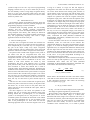
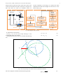
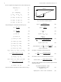
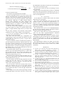
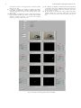
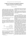
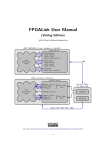
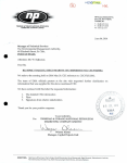
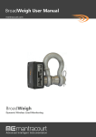
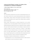
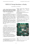
Position Papers of the 2013 Federated Conference on
Computer Science and Information Systems pp. 37–42
7
) &
#
3
"
3
!
Roland Szabó, Aurel Gontean
Applied Electronics Department
Faculty of Electronics and
Telecommunications,
“Politehnica” Univ. of Timi@oara
Timi@oara, România
[email protected]
!
"#
$
"
#
&"'()(
-. $.
%
*)+ *,+
%
/
0
1
0
23 #
4
5
5
6
4
0
I.
INTRODUCTION
T
HIS paper presents an application made in LabVIEW
which can control the robotic arm with stereo cameras.
In the industrial environment most of the robots have no
“eyes”, have no cameras, they just move following the
previously learned paths and they make no decisions during
execution of tasks. Their control software is simple, with no
complications, most of the robots have clear paths with no
obstacles and the engineers are always close to correct if a
problem occurs [1].
As we maybe see in today’s factories the robotic arm are
even separated in cages, so no obstacles can get in their way
and no person can get close to the even accidentally. These
rules of caging robotic arm were are made for user safety,
because these robotic arms can really injure a human if he
gets in their way. If you take a robotic arm programming
class of one semester, you shall see that almost one semester
you just learn the work protection and safety task and only
after than you can get to the fun part, to really program the
robotic arm.
This is all good, but maybe this can’t go forever, there has
to be a time when a robot and human can work together,
c 2013, PTI
37
without to always be aware that a robotic arm can hurt the
operator.
Here comes the computer vision in the robotic industry,
which can change the way robots were controlled.
Of course we know that computer vision was integrated in
the robotic industry even a decade ago, but wasn’t so spread,
and in the industrial robotic arms the cameras for detecting
the robotic arm’s movement weren’t really used. Cameras
were used only for object detection, but not to control the
robotic arms itself.
This way we can get rid of the cages in the industry for
the robotic arms and if an operator or an obstacle gets in the
way of the robotic arm, this can avoid it, or it can stop or
recalculate it’s trajectory on the move.
Another this is we can reduce service and maintenance
time of a robotic arm, because we shall need even less
calibration, because using cameras the arm can detect it’s
position and can auto calibrate.
Maybe this robotic arm detection with camera method is
not very mature, but is a good start. Our idea is to combine
all the robotic arm control algorithms together and not to
replace an existing one. We can use the PTP (Point To
Point) method to teach the trajectory to the robot, we can use
the coordinate system conversion algorithms like the inverse
and forward kinematics; we can use one camera for object
detection and two or more cameras for the robotic arm
position detections in space.
II.
PROBLEM FORMULATION
We had the task quite clear. We had a Lynxmotion AL5
type robotic arm, two webcams and a PC. We could use any
programming environment; the idea was to make the job
done. To create an application which can recognize the
robotic arm in space using computer vision and control it
according to its position using the RS;232 interface.
We could use even other auxiliary object too, which could
help us, but the important fact was to finish the job
successfully.
An idea was to try to find some sort o programming
language which can incorporate all the necessary tasks, to be
simple to use and to program, because in very complex
38
POSITION PAPERS OF THE FEDCSIS. KRAKÓW, 2013
systems it helps no to do it in a very low level programming
language, because this way we never finish the job. To be
also user friendly, to have a string image recognition library
built in, to have great execution speeds and to also have
many communication interfaces built in to be able to control
almost any robotic arm.
III.
PROBLEM SOLUTION
We found the suitable programming language which can
fulfill the requirements from the previous paragraph, this
programming language is called: LabVIEW.
LabVIEW made everything possible, like user friendly
interface and user friendly graphical programming
environment, NI vision Development Module which is a
strong computer vision library, and a library for almost all
the computer interfaces. We could accomplish everything in
only one programming language and create a single
application which can do the entire job.
Our idea was to recognize the robotic arm with the two
webcams, but of course to recognize all the arm would be a
more complicated job, so the best way is to recognize only
key part of the object. Today every object recognition
system recognizes only key characteristics of the object and
upon these a decision is made to recognize the whole object.
We placed some colored bottle stoppers on the joints of
the robotic arm and we recognized these with color
recognition algorithm. These joints were than united with
straight lines and this way we had the skeleton of the whole
robotic arm, which could be introduced in the PC. This
method is used when athletes are tested by their
performance; they have some luminous spots or colored
spots placed on their joints and these spots are united and
their movement is tested. This method also is used in
computer games when animating characters. Sometimes the
animation of the characters is made with the data introduced
from real actors which have these spots on them to recognize
their movements. We used the same principle to our robotic
arm. Of course we can enhance the method by recognizing
some key elements on the robotic arm, like some screws or
bolts, this way we don’t have to place colored objects on
them.
After this we drew circles around each recognized joint,
because the joints of the robot are exactly in the place where
the motors are, so these circles are the paths where the
robotic arm part can move around the center point, which is
the specific motor.
We drew tangents to the circles and parallels to the
tangents, this way we created a 2D coordinate system. This
drawing looked like a parallelogram, so our coordinate
system is not orthogonal, but it’s still good for us. In this
coordinate system can calculate the movement on 0Y and 0Z
axes. The main information for us was the lengths of the
sides of the parallelogram. To know them we used the
following algorithm. First we drew the tangent to the circle
as long as its radius, it is logic too that this tangent is
orthogonal to the radius. We drew the two tangents of the
two circles which had the same starting point, because on
circles had the center in the base joint and the other in the
elbow joint. We knew the target point too. We needed to
compute two parallel lines with the tangents which pass
through the target point. After this with the equation of the
straight line we compute the intersections of one line which
is parallel to the tangent and passes though the target point
and the other line which has the length of the radius and it’s
orthogonal to it. This we knew the exact size of the sides of
the parallelogram. This is the first information; the other is
the size of the radius of the circles, which is also known, so
this way we have an orthogonal triangle, from where we
could compute the angle which needs to move each motor
with arctangent. From this angle we computed the robotic
value, constructed the SCPI (Standard Commands for
Programmable Instruments) command and sent it on the
serial interface [3], [4].
For the movement in the 0X axis we used stereo distance
calculation, where we used both of the cameras. We
computed the distance to the object and the distance two the
gripper, so we used the triangle geometric stereo distance
algorithm twice, we computed their difference and that, from
that the angle and from that the robotic value which was
included in an SCPI command and sent to the robotic arm.
So as we seen with these ideas the robotic arm can be moved
in 3D, and 3 of its joints manipulated according to its
recognized position by the camera.
We needed to compute the robotic values from the angles,
for this we came up with equation (1) [1], [2]. After this we
concatenated these values into the SCPI (Standard
Commands for Programmable Instruments) commands sent
to the robotic arm on the RS;232 interface [5].
(1)
Where 2500 is the maximum and 500 is the minim robotic
value and we know that the motors from the robot can make
a 180º maximum movement. This means the following
shown in equation (2) [1], [2].
(2)
On Fig. 1 we can see the block diagram of the experiment.
The image recognition algorithm is presented next.
We first make a color threshold which can be done to and
RGB (Red, Green and Blue) image or a HSV (Hue,
Saturation and Value) image. This is done for each color, so
four times for the blue, yellow red and green bottle stoppers.
After this we remove the small particles to exclude false
positives and noise. Finally we want to know the exact
coordinate of the searched color, so we make a particle
ROLAND SZABO, AUREL GONTEAN: FULL 3D ROBOTIC ARM CONTROL
analysis and we search the center of the mass, which is the
center of the searched color blob. After this we computer our
lines and circles, we create our coordinate system, we
Logitech C270
Webcams
USB
39
overlay everything on the image, we construct the SCPI
commands and send them thought the VISA driver to the
robotic arm [3], [4].
AL5A Robotic
Arm
Particle
Analysis –
Center of
Mass
Mathematical
Calculations
SCPI
Commands
USB
Remove
Particle
RS;232
PC
Drawing Overlay
on Image
VISA Driver
for RS;232
Color
Threshold
Fig. 1 Block diagram of the experiment
(3)
On Fig. 2 we can see the overlay drawings on the
acquisitioned image with webcam.
The difference between vectors we calculate the following
way.
!
(4)
P5
P6
P1
PT
P2
P7
P0
P4
Fig. 2 The overlay drawings on the robotic arm for the mathematical calculations
The vector length we calculate with the following formula.
""
#
$
(5)
40
POSITION PAPERS OF THE FEDCSIS. KRAKÓW, 2013
We can compute the orthogonal vector in the following way.
%&
(6)
(
')
(
'+
,
')
,
'+
%&
(8)
*
')
*
'+
*
')
*
'+
$
(9)
$
a
b
(10)
$
factor
(11)
$
Fig. 3 Stereo distance calculation algorithm
(12)
0
The parallelogram is calculated the following way.
%!
,
(13)
%
(
(14)
,
(
% $
%!
%! $
%!
-
%
.
%
-
%!
%
-
%
%!
.
-
%!
.
.
%!
.
.
$
%
%!
-
%
%!
/
%
/
$
%
/
%!
%!
%
.
%
/
/
/
$
%!
/
$
4
/
(20)
3
/
(21)
$ %!
(22)
12
%
0<
(28)
(29)
(30)
75
6
2
%
5
2
1
&
(31)
2
75
6
4
2
33
3
>?
4
*
0=
20 2
1
20 @
>
20 @
(24)
The robotic values are calculated the following way.
(25)
*
(26)
(32)
(33)
0=
&
2
:;
(34)
The angle is calculated in the following way.
(23)
$%
*
2
2
&
33
33
32
33
3
5
09
(19)
/
$
08
(18)
%
$
4
33
(17)
%!
$
/
%
.
.
$
/
%!
-
-
0
(16)
%!
1
%
(15)
$
offset
'
(7)
camera separation
'
distance
(35)
(36)
The real world coordinates were converted to pixels with the
following formulas.
@
(27)
The stereo distance calculation is done as shown on Fig. 3.
1 &
A 2
A
1 0 2
G FH
2
2
EF
GDF
B C
D C
G
(37)
IIJ
(38)
ROLAND SZABO, AUREL GONTEAN: FULL 3D ROBOTIC ARM CONTROL
1
M
2
11
21 &
K&
2 K %L H
L
G KIIJL
G D K %L
(39)
The software was implemented in LabVIEW.
We chose LabVIEW, because as we can see on Fig. 4 this
software environment has very friendly and rich UI (User
Interface). It has also the possibility to program almost any
interface of the PC, like serial port (RS;232), USB, parallel
port, Ethernet, IEEE;488 or GPIB (General Purpose
Interface Bus), Bluetooth and IrDA (Infrared Data
Association). It has the libraries in the base package, so no
additional libraries are needed to control the previously
enumerated computer interfaces [3], [4].
It has also a very strong computer vision library which
can control almost any camera on FireWire (IEEE;1394),
USB 2.0, Gigabit Ethernet (GigE Vision) or Camera Link
[1].
It has many computer vision functions which smartly
combined can create a string computer vision application.
As we can see everything to control the robotic arm is
integrated in one single application.
We have first the serial port configuration for
commanding the robotic arm on RS;232 interface. We have
115200 baud rate, 8 data bits, no parity, 1 stop bit and no
flow control. [1], [2]
We have 4 buttons to make to communication possible on
the serial interface between the PC and the robotic arm. The
first button will place the SSC;32 servo control board from
the robotic arm in remote mode and will read its version.
This buttons after it’s pressed it will display the response in
the indicator near it, we can see clearly that we have the
SSC;32 board version 2.01. [1], [2]
The Initialize Motor button will test all the digital port
from the servo control board and the motors it’s self too. We
have 32 digital port, but only 5 motors, from where in our
application we use only 3 motors, but with this button we
test all ports and all motors [1], [2].
With the All Servos 1500 we “wake” the robotic arm , we
put it in the initial position which will look like the Greek
capital gamma letter (Γ) [1], [2].
The move button will start the image acquisition and will
overlay the lines and circles to the original images
acquisitioned by the two webcams. It will also move the
robotic arm in the desired position.
We can see that we have also two drop down boxes to
choose the webcams, this way we can change between
webcams if we have more than two connected to the PC or
we can change their order or switch the right webcam with
the left one.
In the middle we have the left and right images with the
acquisitioned image of the robotic arm ant he overlays after
41
the mathematical calculation. We have the color filtering for
all for colors for left and for right.
We have also 24 sliders for each color filtering to set the
color thresholds.
Finally we have the STOP button, because no LabVIEW
application with loops should be left without it, this way we
can get rid of problems like force quit and end task when we
want to exit the application.
IV.
CONCLUSION
As we could see we created a whole robotic arm control
application all in one program.
The system work surprisingly well, but we know that
nothing is perfect. We think about enhancements of it,
maybe to create it on text based programming language too
or to port it to another operating system, because our system
works now in Windows operating system and in LabVIEW
programming language.
We would also like to port it on an embedded hardware,
this way the only solution could be and FPGA, maybe a
Spartan;6 board like the Digilent ATLYS.
After this we could create even a layout of the chip and
create our own ASIC (Application;Specific Integrated
Circuit), which does the robotic arm control.
Maybe a best enhancement would be to extend to control
of the number of joints, the best goal is to extend the number
of controlled joints from 3 to 7, this way we can please even
NASA’s 7 joint robotic arm from the ISS (International
Space Station).
The implementation solutions are endless, but the basic
idea will stay the same, to use one or more cameras to detect
the robotic arm’s position, not just to know it by “blind”
calculations.
REFERENCES
[1]
[2]
[3]
[4]
[5]
[6]
[7]
[8]
R. Szabó, I. Lie, “Automated Colored Object Sorting Application for
Robotic Arms,”
. Tenth Edition, 2012, pp. 95–98.
R. Szabó, A. Gontean, I. Lie, “Smart Commanding of a Robotic Arm
with Mouse and a Hexapod with Microcontroller,” !"
#$ % , 2012, pp. 476–481.
R. Szabó, A. Gontean, I. Lie, M. BăbăiŃă, “Comparison between
Agilent and National Instruments Functional Test Systems,” "
& , 2010, pp. 87–92.
A. Gontean, R. Szabó, I. Lie, “LabVIEW Powered Remote Lab,” !'
$
(
, 2009, pp 335–340.
)*+ ,
. Available: http://www.lynxmotion.com/images/
data/ssc;32.pdf, last visited April 20, 2013.
Wong Guan Hao, Yap Yee Leck, Lim Chot Hun, “6;DOF PC;Based
Robotic Arm (PC;ROBOARM) with efficient trajectory planning and
speed control,” .
. , 2011, pp. 1–7.
Woosung Yang, Ji;Hun Bae, Yonghwan Oh, Nak Young Chong,
Bum;Jae You, Sang;Rok Oh, “CPG based self;adapting multi;DOF
robotic arm control,”
/ 0
/. , 2010, pp. 4236–4243.
E. Oyama, T. Maeda, J.Q. Gan, E.M. Rosales, K.F. MacDorman, S.
Tachi, A. Agah, “Inverse kinematics learning for robotic arms with
fewer degrees of freedom by modular neural network systems,”
42
POSITION PAPERS OF THE FEDCSIS. KRAKÓW, 2013
/ 0
/. ,
2005, pp. 1791–1798.
[9] N. Ahuja, U.S. Banerjee, V.A. Darbhe, T.N. Mapara, A.D. Matkar,
R.K. Nirmal, S. Balagopalan, “Computer controlled robotic arm,”
!1
)
, 2003,
pp. 361–366.
[10] M.H. Liyanage, N. Krouglicof, R. Gosine, “Design and control of a
high performance SCARA type robotic arm with rotary hydraulic
actuators,”
, 2009, pp. 827–832.
[11] M. C. Mulder, S. R. Malladi, “A minimum effort control algorithm for
a cooperating sensor driven intelligent multi;jointed robotic arm,”
(
*2
$
,
vol. 2, pp. 1573–1578, 1991.
[12] M. H. Liyanage, N. Krouglicof, R. Gosine, “High speed electro;
hydraulic actuator for a scara type robotic arm,”
/ 0
/. , 2010, pp. 470–
476.
Fig. 4 The robotic arm control application made in LabVIEW