1
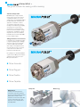
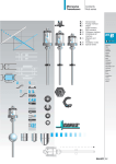
MICROPULSE® Generation 7
Analog Rod-Style Transducers
The global standard for analog position sensing
Generation
eration 7
The global standard for
or analog position sensing
Trusted around the world
Balluff Micropulse® magnetostrictive
linear position sensors have achieved
a worldwide reputation for accuracy,
stability, and rock-solid reliability. Around
und
the globe, Micropulse transducers find
d
applications in industries as diverse
as renewable energy, plastic injection
molding, tire manufacturing, packaging,
ng,
steel production, forest products,
medical devices, and metal forming.
End users, machinery builders, cylinder
er
manufacturers, and hydraulic systemss
integrators who serve these industriess
trust Micropulse to provide dependable
ble
position feedback signals.
Taking performance to the next level
vel
Competition in the manufacturing sector
ctor
is tough and getting tougher. Standing
g
still isn’t an option as pressure builds
to improve quality and productivity
while cutting costs. Equipment has to
o
run better and run longer, so machine
e
components have to deliver more
performance and higher value.
Recognizing these demands, Balluff set
a goal to take the Micropulse transducer
cer
and make it even better. The result—
Micropulse Generation 7.
More Accurate
More Rugged
More Flexible
More Capable
Fluid power
Balluff delivers
In today’s lean-running business
environment, multi-week lead times
just aren’t workable. Balluff’s standard
delivery time for made-to-order
transducers is five business days after
receipt of order. Same day or next
day service is also available with an
expediting adder.
Wind energy
analog rod-style
Enhanced performance, full backward compatibility
The standard Micropulse analog-output rod-style
transducer delivers industry-leading performance,
and it offers 100% backward compatibility to previous
Micropulse generations and magnets.
Key to system performance
Users and installers know that accurate and reliable
position data is critical to getting maximum performance
from a hydraulic positioning system. The proper operation
of all other components – the hydraulic cylinder, the
servo or proportional valve, and the computer motion
controller – is dependent on the validity of the electrical
signal coming from the linear position transducer. The
Micropulse transducer probe, located inside the bore of
the cylinder, detects the position of a magnetic target
installed on the face of the piston, providing continuously
updated absolute position feedback. Micropulse
magnetostrictive technology is wear-free and provides the
correct position reading on start-up, without any need to
re-home the mechanism.
Micropulse+ configuration software
analog rod-style
Enhanced performance, advanced configurability
The Micropulse+ analog-output rod-style transducer
offers industry-leading performance, plus advanced
features and USB configuration capability.
Plastic injection molding
Sawmill equipment
To be truly useful, transducer-based output configuration
has to be simple and frustration-free. With Generation 7,
Micropulse+ sets the standard for flexible yet painless
output configuration. Communicating with the transducer
over standard USB, Balluff’s free PC-based software
offers an intuitive graphical user interface that makes
output configuration almost effortless.
Hydro power
GENERATION 7
and
Performance, compatibility,
configurability
Generation 7
The standard Micropulse
linear position transducer:
The standard
Improved performance; 100% backward compatible
The same...
...only better
®
Order it, receive it, install it, run it. The standard Micropulse
Generation 7 linear transducer is a drop-in replacement for legacy
Micropulse transducers and magnets.
While the standard Micropulse transducer is completely backward
compatible, it offers performance and usability improvements that pay
dividends in real-world linear positioning applications.
Like all Micropulse Generation 7 transducers, the standard Micropulse
transducer delivers significant performance improvements, while
maintaining full backward compatibility with previous Micropulse
generations and magnets.
Performance improvements include:
Compatibility features include:
Identical standard connector and wire color code – Standard
8-pin M16 connector and same wire color code eliminates the
need to re-wire.
Uses the same position magnet – Compatible with all previous
Balluff position magnets. This is especially important in hydraulic
cylinder applications where the magnet is embedded in the
cylinder, and replacement would be costly and time-consuming.
Same (or smaller) mechanical envelope – No worries about
mechanical fit.
Same operating voltage – +10…+30 Vdc power supply range
means that it will operate with +24 Vdc, or +/-15 Vdc power
supplies, right out of the box.
Same push-button setup procedure – Pre-configured with a
variety of standard analog voltage or analog current outputs. If
calibration is ever required, the standard Micropulse is fully scalable
over its mechanical stroke using the included removable pushbutton setup tool. The setup procedure is identical to previous
Micropulse transducers.
Measured variable
Measuring length
Available electrical outputs:
Number of outputs
Analog voltage
Analog voltage
Analog current
Analog current
Voltage versions
Current versions
Configurability
Resolution:
Non-linearity:
Supply voltage
Current draw
Environmental protection:
Operating temperature
Shock load
Vibration
Voltage output
Current output
Stroke length ≤ 500 mm
Stroke length > 500 mm, ≤ 5500 mm
Stroke length > 5500 mm
Connector versions
Integral cable versions
Better ingress protection – Integral cable versions offer IP68
ingress protection, meaning better performance and longer life in
harsh applications.
Increased electromagnetic immunity – Significantly improved
protection against electromagnetic interference, ensuring troublefree operation in electrically “noisy” environments.
Higher shock and vibration ratings – Designed and tested to
withstand the rigors of today’s demanding applications.
Longer available stroke lengths – Available in stroke lengths
from 25 mm to 7620 mm (1" to 300"), in 1 mm increments.
Bi-color LEDs for diagnostics and status monitoring – Bright,
easy-to-see bi-color LEDs provide instant verification of operation
status, and provide visual feedback during the scaling and setup
procedure.
Through-the-connector output scaling – In addition to the
familiar push-button scaling, the standard Micropulse Generation 7
transducer’s output can also be adjusted remotely, through two
teach-in wires at the connector.
New connector options – In addition to the standard 8-pin M16
connector, the standard Micropulse Generation 7 transducer is
available with a smaller, industry-standard 8-pin M12 connector.
Absolute linear displacement
25 mm to 7620 mm
0 to 10 Vdc / 10 to 0 Vdc
-10 to +10 Vdc / +10 to -10 Vdc
0 to 20 mA / 20 to 0 mA
4 to 20 mA / 20 to 4 mA
2, rising and falling (not independently scalable)
1
100% scalable stroke length using included push-button setup tool.
Status LEDs for visual feedback.
≤ 0.33 mV
≤ 0.66 μA
+/- 50 μm
+/- 0.01% of full-scale
0.02% of full-scale
+10 to +30 Vdc
≤ 150 mA @ +24 Vdc
IP 67 (with connector attached)
IP 68
-40 to +85°C
150g/6 ms per IEC 60068-2-27
20g, 10 to 2000 Hz per EN 60068-2-6
For detailed technical specifications and installation guidelines, refer to the Technical User’s Guide, available at www.balluff.com/BTL7downloads
4
+
Micropulse+
linear position transducer:
The
Generation 7 performance, plus advanced configurability
All the performance…
The Micropulse+ offers all of the enhanced performance found in the
standard Micropulse® Generation 7 analog rod-style transducers, plus
advanced features and configurability that make the Micropulse+ the
most versatile linear position transducer available.
Generation 7 performance improvements:
Better ingress protection
Increased electromagnetic immunity
Higher shock and vibration ratings
Longer available stroke lengths
Bi-color LEDs for diagnostics and status monitoring
Output range adjustment – Freely configurable output range
allows the factory default 0-10V or 4-20 mA output to be changed
to any value between -10 to +10V or 0-20 mA.
Select 1- or 2-magnet operation
Select position, differential position, or velocity feedback
Signal inversion – Output signal slope can be instantly configured
as either rising or falling.
Saving/Loading of configuration parameters – Transducer
configuration settings can be saved to a file and then re-loaded
to replacement transducers or emailed to a remote location. For
application troubleshooting, configuration files can be sent to a
knowledge center for analysis.
Restore factory defaults
New connector options
….plus, advanced functionality
The Micropulse+ utilizes innovative, easy-to-use PC-based
configuration software and a standard USB interface to allow
unprecedented configuration and setup options.
In addition to the advanced configuration options available through the
USB interface, the Micropulse+ transducer can be locally configured
using the removable push-button programming tool. The streamlined
Easy-Teach™ setup procedure provides the following functions:
Teach START and END points by moving magnet
Invert signals from rising to falling
USB configuration features:
Stroke length scaling – The factory default electrical stroke can
be easily modified to suit application requirements. A variety of
stroke scaling methods are available:
Adjust signal level at current magnet position (can be done
while transducer remains online/in-process)
Teach-in procedure allows current magnet position to be
read and stored as new START and END points
Teach-in push-buttons can be locked out via the USB
configuration software to prevent tampering
Reset transducer to factory defaults
Direct entry of new START and END point values
Drag-and-drop new START and END points on output graph
Measured variable
Measuring length
Available electrical outputs:
Analog voltage
Analog voltage
Analog current
Analog current
Number of outputs
Configurability
Absolute linear displacement and/or velocity (with or without sign)
25 mm to 7620 mm
0 to 10 Vdc / 10 to 0 Vdc (factory default)
-10 to +10 Vdc / +10 to -10 Vdc (user configurable)
0 to 20 mA / 20 to 0 mA (factory default) (user configurable)
4 to 20 mA / 20 to 4 mA (factory default)
2, independently scalable and configurable for position or velocity feedback
Configurable via PC USB interface. Configurable parameters include:
– Stroke range
– Output type (position, differential
position, or velocity)
Resolution:
Non-linearity:
Supply voltage
Current draw
Environmental protection:
Operating temperature
Shock load
Vibration
Voltage output
Current output
Stroke length ≤ 500 mm
Stroke length > 500 mm, ≤ 5500 mm
Stroke length > 5500 mm
Connector versions
Integral cable versions
– Output slope (rising or falling)
– Output range
– Error output values
≤ 0.33 mV
≤ 0.66 μA
+/- 50 μm
+/- 0.01% of full-scale
0.02% of full-scale
+10 to +30 Vdc
≤ 150 mA @ +24 Vdc
IP 67 (with connector attached)
IP 68
-40 to +85°C
150g/6 ms per IEC 60068-2-27
20g, 10 to 2000 Hz per EN 60068-2-6
GENERATION 7
Generation 7
For detailed technical specifications and installation guidelines, refer to the Technical User’s Guide, available at www.balluff.com/BTL7downloads
www.balluff.com/BTL7-Z
5
Generation 7
How to order
BTL7-
-M
1
and
2
3
1. Choose version:
4
5
or
Refer to the table comparing the features of the Micropulse and Micropulse+.
Feature
Diagnostic/setup LEDs
Two position outputs (rising/falling)
with one magnet
Second output configurable for independent
position of second magnet, velocity, speed,
or differential distance
Pushbutton setup:
Teach zero/span
Adjust signal online/in-process
Reset to factory defaults
Reset to last good teach
Invert outputs (rising/falling)
Legacy Balluff push-button procedure
Easy-Teach™ push-button procedure
Setup via discrete lines through
cable/connector
USB-configurable with software
Micropulse+
Micropulse
2. Choose output signal
Use the table below to choose the correct output signal.
Note the ordering code designation in bold.
Output type
0...10V and 10...0V
-10...+10V and +10...-10V
4...20 mA
20...4 mA
0...20 mA
20...4 mA
Ordering Code
Micropulse
BTL7 - A510 - M _ _ _ _ - _ - _ _ _ _
BTL7 - G510 - M _ _ _ _ - _ - _ _ _ _
BTL7 - E510 - M _ _ _ _ - _ - _ _ _ _
BTL7 - E570 - M _ _ _ _ - _ - _ _ _ _
BTL7 - C510 - M _ _ _ _ - _ - _ _ _ _
BTL7 - C570 - M _ _ _ _ - _ - _ _ _ _
Micropulse+
BTL7 - A501 - M _ _ _ _ - _ - _ _ _ _
BTL7 - A501 - M _ _ _ _ - _ - _ _ _ _ (user configurable)
BTL7 - E501 - M _ _ _ _ - _ - _ _ _ _
BTL7 - E501 - M _ _ _ _ - _ - _ _ _ _ (user configurable)
3. Choose measuring range
The nominal stroke of the Micropulse
transducer is expressed in millimeters,
from 0025 mm up to 7620 mm.
Example:
BTL7 - _ _ _ _ - M1524 - _ - _ _ _ _
The overall length of the rod includes the
nominal stroke + the NULL zone + the
DAMPING zone.
Note: To convert inches to millimeters, multiply by 25.4. Example: 60" x 25.4 = 1524 mm.
6
Generation 7
How to order
GENERATION 7
4. Choose mounting flange/thread type and rod diameter
Use the table below to choose the mounting flange/mounting thread combination. Note the ordering code designation in bold.
Flange configuration/Rod diameter:
3/4”-16 UNF threads,
raised-face mounting flange,
Ø10.2 mm rod
Ordering Code:
BTL7 - _ _ _ _ - M _ _ _ _ - Z - _ _ _
(Standard configuration)
Flange configuration/
Rod diameter:
3/4"-16 UNF threads,
raised-face mounting flange,
Ø8 mm rod
(max stroke length = 1016 mm)
Flange configuration/
Rod diameter:
M18 x 1.5 threads,
raised-face mounting flange,
Ø10.2 mm rod
Flange configuration/
Rod diameter:
M18 x 1.5 threads,
raised-face mounting flange,
Ø8 mm rod
(max stroke length = 1016 mm)
Flange configuration/
Rod diameter:
M18 x 1.5 threads,
flat-face mounting flange,
Ø10.2 mm rod
Flange configuration/
Rod diameter:
3/4”-16 UNF threads,
raised-face mounting flange,
Ø10.2 mm rod
Ordering Code:
BTL7 - _ _ _ _ - M _ _ _ _ - Z8 - _ _ _
Ordering Code:
Ordering Code:
Ordering Code:
Ordering Code:
BTL7 - _ _ _ _ - M _ _ _ _ - B - _ _ _ BTL7 - _ _ _ _ - M _ _ _ _ - B8 - _ _ _ BTL7 - _ _ _ _ - M _ _ _ _ - A - _ _ _ BTL7 - _ _ _ _ - M _ _ _ _ - Y - _ _ _
Magnet
5. Choose connector type or integral cable
S115 = 8 pin M12 micro connector
S32 = 8 pin M16 DIN connector
KAxx = Integral PUR cable (specify length xx in meters)
Full ordering codes
Ordering example:
BTL7 -
Output signal
A 0...10V and 10...0V
G -10...+10V and +10...-10V
E 4...20 mA
C 0...20 mA
Ordering example:
BTL7 -
Output signal
A Voltage (user configurable)
E Current (user configurable)
www.balluff.com/BTL7-Z
5
0-M
-
Mounting threads
Z = Standard 3/4"-16 UNF
Output signal
1 for A and G rising and falling
0 for C and E rising
7 for C and E falling
501 - M
-
Nominal stroke in millimeters
0025 mm to 7620 mm
in 1 mm increments
Connection type
S115 8-pin M12 connector
S32 8-pin M16 connector
KA02 PUR cable 2 m
KA05 PUR cable 5 m
KA10 PUR cable 10 m
KA15 PUR cable 15 m
Mounting threads
Z = Standard 3/4"-16 UNF
Nominal stroke in millimeters
0025 mm to 7620 mm
in 1 mm increments
Connection type
S115 8-pin M12 connector
S32 8-pin M16 connector
KA02 PUR cable 2 m
KA05 PUR cable 5 m
KA10 PUR cable 10 m
KA15 PUR cable 15 m
7
Generation 7
Mechanical dimensions
Version
BTL7- _ _ _ _-M_ _ _ _-Z-_ _ _ _
BTL7- _ _ _ _-M_ _ _ _-Y-_ _ _ _
BTL7- _ _ _ _-M_ _ _ _-B-_ _ _ _
BTL7- _ _ _ _-M_ _ _ _-A-_ _ _ _
Null zone (N)
50.8 mm
50.8 mm
30 mm
30 mm
Version
BTL7- _ _ _ _-M_ _ _ _-A-_ _ _ _
BTL7- _ _ _ _-M_ _ _ _-B-_ _ _ _
BTL7- _ _ _ _-M_ _ _ _-Y-_ _ _ _
BTL7- _ _ _ _-M_ _ _ _-Z-_ _ _ _
BTL7- _ _ _ _-M_ _ _ _-A8-_ _ _ _
BTL7- _ _ _ _-M_ _ _ _-B8-_ _ _ _
BTL7- _ _ _ _-M_ _ _ _-Y8-_ _ _ _
BTL7- _ _ _ _-M_ _ _ _-Z8-_ _ _ _
Rod diameter (Ø D1)
8
10.2 mm with M4 x 6
threaded hole at end
8 mm
(no threaded hole)
Mounting threads
¾"-16 UNF
50.8 mm ¾"-16 UNF
M18 x 1.5 raised-face
M18 x 1.5 flat-face
Mounting surface
raised-face (standard)
flat-face
raised-face
flat-face
Generation 7
Accessories
version only
Connection at the transducer
USB Interface kits
GENERATION 7
USB connection options –
BTL-A-CB01-USB-S115
to host controller
USB communication box
BTL7-A-CB01-USB-S115
for BTL7-A/E501...with S115 connector
BTL7-A-CB01-USB-S32
for BTL7-A/E501...with S32 connector
Connection at the control panel
to host controller
BTL-A-CB01-USB-S32
SB-S32
BTL-A-CB01-USB-KA
SB-KA
Max length = 100 m
USB communication box
BTL7-A-CB01-USB-KA
to access communication at the panel
or for BTL7-A/E501...with integral cable
Online resources
PC software, software user’s manual, and transducer user’s manuals
can be downloaded at www.balluff.com/BTL7downloads
www.balluff.com/BTL7-Z
Software tutorials and product information videos
are available at www.balluff.com/BTL7videos
9
Generation 7
Accessories
S115 Connectors and Cables
Description
For version
Part number
Number of conductors
Conductor cross section
Contacts
Wire connection
Cable jacket material
Cable jacket diameter
Housing material
Min. bend radius
Enclosure rating per IEC 60529
Connector,
Molded connector with cable,
female, straight, M12
female, straight, M12
Generation 7 Micropulse and Micropulse+ Rod-Style Transducers
BKS-S115-00
BKS-S115-PU-_ _*
8
8
n/a
0.25 mm2
Brass, gold-plated
Brass, gold-plated
Screw terminals
n/a
n/a
Molded-on PUR
6...8 mm
6.6 +/-0.2 mm
Nickel-plated brass
Nickel-plated brass and PUR
Cable dependent
Dynamic = 5 x Ø
Static = 3 x Ø
IP 67 (when attached)
IP 67 (when attached)
Molded connector with cable,
female, right angle, M12
BKS-S116-PU-_ _*
8
0.25 mm2
Brass, gold-plated
n/a
Molded-on PUR
6.6 +/-0.2 mm
Nickel-plated brass and PUR
Dynamic = 5 x Ø
Static = 3 x Ø
IP 67 (when attached)
* = Indicate cable length when ordering
00 = no cable, field-installable
(use shielded cable)
02 = 2 meters
03 = 3 meters
05 = 5 meters
10 = 10 meters
15 = 15 meters
20 = 20 meters
25 = 25 meters
Additional cable lengths available on request
S32 Connectors and Cables
Description
For version
Part number
Number of conductors
Conductor cross section
Contacts
Wire connection
Cable jacket material
Cable jacket diameter
Housing material
Min. bend radius
Enclosure rating per IEC 60529
* = Indicate cable length when ordering
00 = no cable, field-installable
(use shielded cable)
02 = 2 meters
03 = 3 meters
05 = 5 meters
10 = 10 meters
15 = 15 meters
20 = 20 meters
25 = 25 meters
Additional cable lengths available on request
10
Connector, female, straight, M16
Connector, female, right angle, M16
Generation 7 Micropulse and Micropulse+ Rod-Style Transducers
BKS-S 32M-_ _*
BKS-S 33M-_ _*
8
8
0.25 mm2
0.25 mm2
Brass, gold-plated
Brass, gold-plated
Solder
Solder
PUR
PUR
7 mm
7 mm
Nickel-plated brass
Nickel-plated brass
Dynamic = 5 x Ø
Dynamic = 5 x Ø
Static = 3 x Ø
Static = 3 x Ø
IP 67 (when attached)
IP 67 (when attached)
Generation 7
Accessories
Wire-side
view of
female
mating
connector
Function
Micropulse
Pin Wire Color Voltage output version
1 YE (yellow) signal common
2 GY (gray)
signal common
3 PK (pink)
output signal (falling)
4 RD (red)
La (programming input)
5 GN (green) signal output (rising)
6 BU (blue)
supply GND
7 BN (brown) +10...30 Vdc input power
8 WH (white) Lb (programming input)
Current output version
signal common
signal common
not used
L a (programming input)
signal output
supply GND
+10...30 Vdc input power
L b (programming input)
Micropulse+
Voltage output version
signal common
signal common
output signal (falling)1
L a (communication line)
signal output (rising)1
supply GND
+10...30 Vdc input power
L b (communication line)
Current output version
signal common
signal common
output signal (falling)1
La (communication line)
signal output (rising)1
supply GND
+10...30 Vdc input power
Lb (communication line)
Notes: 1 = Indicates factory default setting. Rising/falling characteristic is configurable.
Wiring Table - S32 Connector or KAxx Integral Cable
Wire-side
view of
female
mating
connector
Function
Micropulse
Pin Wire Color Voltage output version
1 YE (yellow) signal common
2 GY (gray)
signal common
3 PK (pink)
output signal (falling)
4 RD (red)
La (programming input)
5 GN (green) signal output (rising)
6 BU (blue)
supply GND
7 BN (brown) +10...30 Vdc input power
8 WH (white) L b (programming input)
Current output version
signal common
signal common
not used
L a (programming input)
signal output
supply GND
+10...30 Vdc input power
L b (programming input)
Notes: 1 = Indicates factory default setting. Rising/falling characteristic is configurable.
www.balluff.com/BTL7-Z
Micropulse+
Voltage output version
signal common
signal common
output signal (falling)1
L a (communication line)
signal output (rising)1
supply GND
+10...30 Vdc input power
L b (communication line)
Current output version
signal common
signal common
output signal (falling)1
L a (communication line)
signal output (rising)1
supply GND
+10...30 Vdc input power
L b (communication line)
GENERATION 7
Wiring Table - S115 Connector
11
Generation 7
Accessories
Magnets
Description
for version
Ordering code
Part number
Material
Weight
Operating/Storage
temperature
Stainless steel
float magnets also
available for liquid
level applications.
Refer to main
Micropulse catalog.
Ring Magnet
BAM013L*
BTL-P-1013-4R
Aluminum
approx. 12 g
-40...+100 °C
Slotted Magnet
Ring Magnet
Ring Magnet
Ring Magnet
Generation 7 Micropulse and Micropulse+ Rod-style Transducers
BAM013P*
BAM013J*
BAM013R
BAM013H
BTL-P-1013-4S
BTL-P-1012-4R
BTL-P-1014-2R
BTL-P-0814-GR-PAF
Aluminum
Aluminum
Aluminum
Ferrite, bound in polyamide
approx. 12 g
approx. 12 g
approx. 10 g
approx. 1.5 g
-40...+100 °C
-40...+100 °C
-40...+100 °C
-40...+100 °C
*Includes spacers
Jam Nuts
Jam nut, 3/4"-16 UNF
Jam nut, M18x1.5
Generation 7 Micropulse and Micropulse+ Rod-Style Transducers
BAM0117
BAM0118
BTL-A-FK01-E3/4"-16UNF
BTL-A-FK01-M18x1.5
Stainless steel
Stainless steel
.Oççsç%DITIONççsççsç0RODUCTçSPECIlCATIONSç
AVAILABILITYçANDçPRICINGçAREçSUBJECTçTOçCHANGEçWITHOUTçNOTICE
Description
For version
Ordering code
Part number
Material
www.balluff.com/BTL7-Z
This brochure was printed on FSC Certified Paper. It
represents Balluff’s commitment to helping the environment.
USA
Balluff Inc.
8125 Holton Drive
Florence, KY 41042
Phone: (859) 727-2200
Toll-free: 1-800-543-8390
Fax: (859) 727-4823
E-Mail: [email protected]
Canada
Balluff Canada, Inc.
2840 Argentia Road, Unit #2
Mississauga, Ontario L5N 8G4
Phone: (905) 816-1494
Toll-free: 1-800-927-9654
Fax: (905) 816-1411
E-Mail: [email protected]
Mexico
Balluff de Mexico S.A. de C.V
Prol. Av. Luis M. Vega #109
Col. Ampliacion Cimatario
Queretaro, QRO 76030
Phone: (++52 442) 212-4882, 224-3583, 224-3171
Fax: (++52 442) 214-0536
E-Mail: [email protected]