1
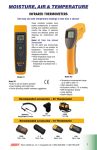
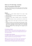
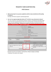
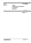
Indiana University-Purdue University Fort Wayne Department of Engineering (ME 487 - 488) Senior Design Project Report #2 Project Title: Banjo Fitting Leak Testing Device Team Members: James Cramer Colby Maust Andy Sipe Anthony Zimmerman Advisor: Dr. Mueller Date: 5/6/2013 Table of Contents Acknowledgements ..................................................................................................................... 3 Abstract ....................................................................................................................................... 4 Section I: Conceptual Design ....................................................................................................... 5 Section I.i Description of Overall Design ................................................................................... 6 Section I.ii Description of Individual Components ..................................................................... 8 Section I.iii Preliminary Modifications ..................................................................................... 10 Section II: Build Process ............................................................................................................ 11 Section II.i Machining of Parts and Initial Assembly ............................................................... 12 Section II.ii Difficulties ............................................................................................................. 15 Section II.iii Modifications ....................................................................................................... 16 Section II.iv Operator’s Manual ................................................................................................ 17 Section II.v Programming Setup ............................................................................................... 17 Section II.v.a Programming Testing Equipment................................................................... 17 Section II.v.b Programming Testing Equipment .................................................................. 19 Section III: Testing ..................................................................................................................... 21 Section III.i Test Parameters ..................................................................................................... 22 Section III.ii Test Procedures .................................................................................................... 22 Section III.iii Data and Analysis ............................................................................................... 23 Section IV: Evaluation and Recommendations ........................................................................ 25 Section IV.i Evaluation ............................................................................................................. 26 Section IV.ii Recommendations................................................................................................ 26 Section V: Conclusions ............................................................................................................... 27 Section V.i Conclusions ............................................................................................................ 28 Ac know ledge ments Special thanks to EPCO Products of Fort Wayne for sponsoring this project and guiding us along the way. Thank you especially to Bill Johnson, Inductrial Engineer and Fredric Aichele, President for all of your help and guidance throughout the project. We would like to thank Matt Wenger at PHD, Inc. for all of his help in the FEA analysis. We would also like to thank Dr. Mueller for his help as our advisor, and Dr. Abu-Mulaweh for helping to oversee the project. Abstract EPCO Products manufactures banjo fittings for use in systems such as automobile brakes, heating and cooling, and robotics, among many others. Each banjo fitting consists of two cylindrical components joined by brazing. However, the brazing is subcontracted to another company that does not guarantee their work. EPCO wishes to guarantee their products as zero leak, but cannot do this unless each unit is tested to ensure the brazing has properly sealed the two components together. Due to this, EPCO is in need of a device that will test each fitting for leaks in the brazing before they leave the facility for use. The testing device needs to be able to adapt to all the various sizes and types of banjo fittings that EPCO manufactures. The device must pressurize each banjo fitting using the line pressure provided at their facility and be quick and easy to operate. The purpose of this report is to completely describe the build process based off of the design described in Report #1 and the operation of the device. Section I: Conceptual Design Section I.i Descripti on of Overall Design The leak testing apparatus built for EPCO Products features a partially automated design shown below. The completed apparatus is shown in figure 1 and figure 2 shows the CAD model generated during the design phase. The system requires limited operator input at a low technical level. The design calls for the operator to manually place a banjo fitting into the enclosure for testing. The base plate of the enclosure contains a “nest”, unique to each model of banjo fitting produced by EPCO. The operator places the fitting into the nest, which has been designed to provide a close fit, and ensure proper orientation during the testing procedure. The nest also acts as a device to prevent the fitting from tipping when force is applied to seal the fitting via the two cylinders. Figure 1: Completed Assembly Figure 2: Original CAD Model Once the fitting is placed in the nest, the operator will begin the test by depressing the two large black buttons simultaneously. The vertical cylinder extends to the fitting and applies a force that effectively seals the top orifice of the fitting. The horizontal cylinder extends toward the fitting at a slower speed. This is accomplished by a smaller orifice that pressurizes the bore of the cylinder at a slower rate. When sufficient force is applied and the fitting is sealed, a check valve opens in the vertical cylinder. This pressurizes the air in the fitting. The pressure is measured on both sides of the fitting. The leak testing device senses any minute difference in the pressure readings and signals a failed test by lighting the red LED and producing a long beep followed by a short beep. If no pressure difference is measured, the green LED indicates a passing test. Figure 3 shows a diagram of the fluid flow in the system. Figure 3: The fluid power diagram Section I.ii Descripti on of Individual Components The assembly of parts designed to align and support the fittings during testing consists of the nest, manifold, and dowel pins, all shown in Figure 4. This sub assembly, shown assembled in Figure 5, is supported by the platform, as shown in Figure 6. The short brace and two long braces are assembled above the nest to form the tower on which the vertical cylinder is mounted. The horizontal cylinder is mounted to the platform using simple corner brackets. Figure 4: The nest (top) is aligned on the manifold (bottom) via the (2) dowel pins. Pressurized air is supplied to the manifold via a 1/8 NPT port in the bottom. A groove is cut for an O-ring to provide a static seal between the nest and manifold. The nest is joined to the manifold using four socket head cap screws. Once the assembly is complete and functioning, these four screws are all that will need to be changed to swap between different nests. Figure 5: The nest and manifold sub assembly Six screws secure the nest sub assembly to the platform. The nest is not shown in this view in order to show the orientation of the manifold and dowel pins. Figure 6: The manifold attached to the platform Figure 7 shows the tower assembled on top of the platform. This sub assembly will be installed in the enclosure. The cylinders are mounted in the appropriate positions, and the leak tester is installed per instructions from the manufacturer. Figure 7: The assembly ready for the installation into the enclosure Section I.iii Preliminary Modifications Before we began the build process, we made a few changes to the conceptual design due to some discussion with Bill Johnson of EPCO Products and due to our own decisions. First of all, it was recommended that we make the whole unit a rolling cart, for ease of relocation and ergonomics. This could be easily accomplished by using the 80/20 parts that we already planned on using for the apparatus. We also were asked to change the thickness of the testing platform from .5” to .75” for added strength in the case of future modifications or additions. Lastly, it was decided that it would be best to redesign the manifold to be a square profile rather than circular. This was done for multiple reasons the first of which was to save on machining costs. Secondly, if the manifold is square it could be used as a fixture for machining the nest, in order to correctly align the cutout in the nest with the location of the horizontal pneumatic cylinder. All of these changes were incorporated into our final built unit. Section II: Build Process Section II.i Machining of Parts and Initial Asse mbly The design of the leak testing device consisted of a mix of custom-machined and commodity parts. The building process was completed in stages, as the completed parts were received. This section details the steps we followed between CAD models and a working prototype. The largest and most expensive component of the design is the testing platform. We did not oversee the machining of this piece. The sponsor used a preferred vendor, as the CNC mill available to us would not accommodate the 2’ x 2’ size of the platform. A technical drawing was not necessary for the platform. We supplied the sponsor with an accurate CAD model of the platform, which was used by the vendor to create the CNC code directly from the model’s geometry. No manual programming was needed. Figure 8 shows the machined testing platform with a few modifications made during the build process. Figure 8: Underside of the machined testing platform The rest of the custom-designed components were machined in the model shop of PHD, Inc. The machining of these pieces was overseen by Andy Sipe and Anthony Zimmerman. The components produced at PHD include the manifold, the nest, the rod end tips, and the support structure for the vertical cylinder. With the exception of the rod end tips, all of these components were machined using a CNC vertical mill. The tips were produced using a CNC lathe. The programs for these components were input manually, with the geometry defined in technical drawings. As mentioned above, we changed the profile of the manifold from circular to square. This change served two purposes. Both purposes involve an important lesson we learned during the design and building processes. In CNC machining, straight lines are cheaper and more useful than round profiles. The nest has a circular profile, which necessitated a fixture for machining in the mill. Since the manifold was produced with a square profile, and the two pieces were aligned with precision fit dowel pins, the manifold served a dual purpose as both a finished part and the nest fixture. The nest, approximately 60 percent complete, is shown in Figure 9. The square of aluminum underneath is the manifold acting as a fixture. Figure 9: Machining of the Nest Once all of those custom parts were made and the commodity parts were purchased, we began the initial assembly. Referring to Figure 1, notice the horizontal rails supporting the platform. These four pieces of 80/20 extrusion were fastened to four short scraps of the same extrusion, which were left over from an earlier project, acting as legs. This provided us with a way to elevate the platform off the work bench. It was in this configuration that the initial prototype was developed. The support structure for the vertical cylinder, shown in Figure 10, must be fastened to the platform first. It is secured from the bottom of the platform using four socket head cap screws (SHCS). The manifold that supports the nest is then secured to the underside of the testing platform using six SHCS. The appropriate O-ring was placed in the groove on the manifold, and the nest was then installed and secured to the manifold. It is critical that the alignment cutout in the nest be oriented toward the mounting holes for the horizontal pneumatic cylinder this cylinder is mounted to the testing platform with foot mount brackets. Figure 10: Vertical cylinder mounted to the support structure prior to assembly At this point, manually actuated pneumatic valves were connected to the cylinders to test the alignment of the assembly. Notice in Figure 11 that the cylinders are extended to the point that they contact the banjo fitting, showing that they will provide a proper seal once the polyurethane caps are installed. Figure 11: The first mockup of the system In order to complete a working prototype, the testing system was assembled and installed using mostly permanent parts, as well as some temporary substitutions. This system is described in detail in Section II.v. The first functioning prototype is pictured in Figure 12. This prototype produced an accurate test on the first trial. Figure 12: The initial prototype Section II.ii Difficulties We did not run into very many difficulties in the building process of this apparatus. However, as mentioned above, there was some confusion with the height of the testing platform that we worked out with our sponsor and came to an agreement on. We also had some issues with the Oring that creates the seal on the bottom of the banjo fittings. After 20-30 trials, there seemed to be a small amount of wear or deformation on the O-ring. It was decided that we should increase the thickness of the O-ring, while keeping the inner diameter the same. After roughly 100 trials, the adhesive fastening the polyurethane cap to the rod end tip of the horizontal cylinder failed. Section II.iii Modifications During the building process there were a couple minor modifications made to the design. Early on in the testing it was discovered that the hardness of our rubber tips for the cylinders was not going to be good enough. The pressure of the cylinders was causing the rubber to deform quite a bit and we decided this could cause problems after many cycles. To begin with we were using 60 Shore rubber, and after our test results we increased the rubber tips to a 90 Shore hardness. We also opted to go with a larger more beefy O-ring in the nest, to withstand the wear and tear put on it from many cycles. The original height of the testing platform from the floor seemed like it may be a problem for the user. It was low enough that it could cause the user to lean over too much and create back problems. It was also at a height where the line of vision from the user would be obstructed by the top bar of the 80/20 case. Due to both of these issues, the height of the platform was raised by 5 inches after consulting with Bill Johnson of EPCO Products. In our testing we also realized that the original cutout we were using to aid in alignment of the banjo fitting was not going to work the way we wanted it to. To take care of this issue, two small vertical dowel pins were added on the top of the nest so that the horizontal part of the banjo fitting could be placed in the exact position needed for alignment with the side hydraulic cylinder. The nest with added dowel pins is shown in Figure 13. Figure 13: Nest with Dowel Pins for Alignment Section II.iv O perator’s Manual The requirements and specifications of the project called for a user manual to be produce to guide new users on how to operate the device. This was completed by James Cramer using Adobe Illustrator CS5. The manual points out the following key pieces of information. Safety measures to take note of before operating the device Overview of device including identifying components and their locations How to run a test including Pass/Fail identification Replacing of the nest and cylinder caps Information on the PLC Programmer Section II.v Pr ogramming Setup Section II.v.a Programming Tes ting Equipment As mentioned in the final modifications section of this report, one of the major changes that occurred was the use of a PLC microcontroller instead of time based relays. Initially when confronted with this decision, the group thought that it would be better to use time based relays based on the ease of replacement and modification. The group also had concerns with the lack of experience of PLC programming that the group members had, as well as the operators and engineers at EPCO products. The group decided to raise this issue with Bill Johnson of EPCO products and he agreed that relays would probably be better suited to meet the needs of the banjo fitting leak testing device. After the group began building the machine, we quickly realized that the use of some sort of logic controller was inevitable. Using a PLC presented a challenge because none of the group members had programmed a PLC controller before, nor had Bill Johnson at EPCO products. The goal was to find a relatively inexpensive PLC programmer that we could program easily and could be easily modified by an employee at EPCO products. We decided to go with a Trol systems T6 microcontroller, as seen in figure 14, with a detachable handheld programmer and expansion module. The Trol systems T6 microcontroller had six inputs and four outputs and could output both DC and AC power. The expansion module provided us with an additional six inputs and four outputs which was more than we needed to meet the requirements of the project. Using a logic controller with a handheld programmer would ease the programming and modification in the future. Figure 14: Trol Systems T6 microcontroller. Starting with the PLC we then moved forward with the components that we would need to test. We selected two 2-way 2-position pneumatic valves from SMC. These valves would allow us to briefly pressurize or exhaust the air into and out of the banjo fitting to test for leaks. These valves had to only have one port in and two ports out. When the valve would shift it would allow air into the banjo fitting. The valve was back fed so there was always pressure to one side of the valve depending if it was in position one or position two. Position one (home, or deenergized, position) was plugged using a ¼” hose plug. Position two provided an air path to the banjo fitting so that the fitting could be filled to reach its maximum pressure. The exhausting valve was hooked into the entire system so that it could relieve pressure at the end of the test cycle before the cylinders retracted to release the banjo fitting. It was important to isolate the two systems of the cylinder actuation and the pressurization for two main reasons. The first reason was that we did not want the natural system leakage of the two banjo fittings to result in excessive leak over time or provide false bad tests. The second reason is that if EPCO products ever decided that they wanted to supply the banjo fitting or cylinders with a different air pressure, they could supply each subsystem individually. In the same banjo fitting test system there was a pressure normally open (NO) switch hooked up that monitored the drop in pressure. If the drop in pressure was greater than what was considered allowable, the NO contact would become open and would not provide signal to the input side of the PLC. It was especially important for us to find the system leak of the testing subsystem to provide an accurate pressure drop that would result in a bad test. The cylinders were actuated using a Norgren 2-position 3-way valve. We had to use a 3-way valve because when the cylinders extend or retract, the opposite end would need to evacuate air to the atmosphere. For example: If the cylinder is extending, there must be a flow path on the retract side that allows air to escape freely to the atmosphere. Otherwise the system will become pneumatically locked in place. The 2-position portion of the valve provided just two operations: extend and retract. Section II.v.b Programming Testing Equipment Programming the T6 PLC was easy and very straightforward using the supplied manual from Trol systems. A list of inputs and outputs can be seen in table 1. The first check of the system was in place for safety. Input 1 checked that the push buttons were in the normally closed position (raised). This would prevent a button from being held or taped down. This would stop an operator from being able to operate the push buttons with one hand. The second check then waited for both push buttons to be pressed down and make contact with the NO contacts. The push buttons were wired in series so both push buttons needed to be pushed down in order to complete the circuit. Once that condition was satisfied the testing operation took place. The outputs begin with the 2-position 3-way valve being energized and providing pressure to extend the two cylinders. The system is set to wait for three seconds before moving to output number 2. Output number two provides pressure for one second to the banjo fitting until it is shut off. The system now waits for three seconds to check for input number 3. If the NO pressure switch is in the closed position, it sends a signal to the PLC that indicates a good banjo fitting. In the case of a good banjo fitting the output then becomes to exhaust the remaining air by activating output 3 and turns on the green light using output 4. This happens for three seconds until output 1 is turned off which retracts both cylinders. At this point the program ends and starts over. In the case of a bad banjo fitting test, input 3 will not be satisfied and will switch to a different portion of the program that outputs the red LED light and the alarm. The program ends after a 5 second period and the cylinders are retracted back to the home position. There are eight additional inputs and two additional outputs that are currently available in the system. This was left this way so that EPCO products could add in additional testing requirements or safety mechanisms (such as a light curtain or proximity sensor). Typically there are several inputs that need to be satisfied to activate an output. The reason for this is usually safety. One of the other programming recommendations is that there be a proximity sensor that senses a banjo fitting in the nest. This would be simple to add as an addition to the system. All that we would have to do is add an additional input requirement for the test cycle to start after the push buttons are pressed. Table 1: List of inputs and outputs using the T6 microcontroller and expansion module. Notice that there are 8 outputs and 12 inputs. # 1 2 3 4 5 6 7 8 9 10 11 12 Input Push button NC contact Push button NO contact Pressure switch Not used Not used Not used Not used Not used Not used Not used Not used Not used Output 2-pos 3-way valve Pressurizing 2-pos 2-way valve Exhausting 2-pos 2-way valve Green LED Red LED Alarm Not used Not used n/a n/a n/a n/a Section II.vi Final Assembly The final assembly consisted of assembling the 80/20 cart and replacing the temporary system components with their permanent replacements. The final steps in completing the system were installing the dual palm buttons for initiating the test, and the permanent indicating lights. A full view of the apparatus can be seen in Figure 1. A front view of the testing platform shows the portion of the device with which the operator will interact. We designed for a clean, uncluttered appearance, and this is shown in Figure 15. Figure 15: The final assembly Section III: Testing Section III.i Test Parameters The following are the parameters that our group will be testing to verify that our design meets all requirements and specifications. 1. Test to make sure that the apparatus cannot initiate testing while someone is obstructing operation. 2. Test to make sure that the total time of operation does not exceed one minute. 3. Test to make sure that the rubber seals are properly creating a seal on the cylinder. 4. Test to make sure that the leak tester properly detects a leak to the given specification. 5. Observe the wear of the polyurethane caps over the course of 100 cycles and compare to that of a new cap to determine a potential life time of the material. Section III.i i Test Procedures The following are the procedures for the tests listed in Section III.i above. Test Setup 1: Two-button Safety 1. 2. 3. 4. 5. Place a fitting into the nest. Press and release only the left button. Observe if the device begins the testing procedure. Press and release the right button. Observe if the device begins the testing procedure. Test Setup 2: Operation Time 1. Using a stopwatch, time the full process of testing a banjo fitting including the time needed to place and remove the banjo fitting from the nest. 2. Start stopwatch. 3. Pick up and place banjo fitting into nest. 4. Depress both buttons to begin test. 5. Wait for test to complete. 6. Remove banjo fitting from the nest. 7. Stop the stopwatch and record the time. 8. Repeat steps 1-7 with for all four team members, the group advisor, and an EPCO employee. 9. Compare the times to the 1 minute requirement. Test Setup 3: Caps Ability to Seal 1. 2. 3. 4. Place a known good banjo fitting in the nest. Begin the test. Observe the pressure drop of the fitting during the test using an external gauge. The observed pressure drop will be considered system leakage and be used as a standard for testing bad fittings 5. Confirm that the device did not detect a leak larger than the established system leak by indicating with the green light that the fitting is good. Test Setup 4: Leak Detection 1. 2. 3. 4. 5. Place known bad banjo fitting into the nest. Run the test to observe the outcome. Observe the pressure drop of the fitting during the test using an external gauge. Compare the pressure drop to that of the established system leakage from Test 3. Confirm that the gage shows a total pressure drop of more than the established criteria to fail a part. 6. Note whether the device indicates the failed test. Test Setup 5: Polyurethane Deterioration Observe the wear of the polyurethane caps over the course of 100 cycles and compare to that of a new cap to determine a potential life time of the material. Both caps will be testing simultaneously by repeatedly running a test with a banjo fitting in place. If either of the caps appears unusable after the 100 cycles then the test has failed. Section III.i ii Data and Analysis The following shows the data and measurements that we obtained while running the required tests for this apparatus. Test 1: Two-Button Safety Test This was a fairly simple test to run that didn’t require any specific data acquisition. When each member of our group attempted to initiate the apparatus my only pressing one button at a time, the apparatus did not initiate testing. This outcome shows that the two-button safety feature adequately protects the user. Test 2: Operation Time While all four group members attempted to run a test of both a known good and known bad banjo fitting, a stopwatch was used to keep track of the time. The average for all group members’ trials came out to 14.7 seconds. Next, we properly instructed Bill Johnson of EPCO products on how to operate the apparatus. He also ran the test for a known good and known bad banjo fitting. Bill’s average cycle time was found to be 15.2 seconds. And lastly, Dr. Mueller was also instructed on how to operate the apparatus. His average test time of a known good and known bad banjo fitting was 16.1 seconds. Test 3: Caps Ability to Seal After we hooked up a pressure gage to our airline to test for system leakage, we ran a test on a known good banjo fitting. This was done ten times to find an accurate reading. The system leakage consistently came out at 9psi throughout the 3 second testing time. This system leakage is something we will look to improve in the future by using higher quality fittings and sealing up problem areas, but for now it is what we have to work with. Because the system leakage is consistent at 9psi, this was used as a standard to help us determine a bad fitting. This process is explained more in the next section. Even with the system leakage, the total pressure drop did not exceed the established 10psi for this fitting, so the green light turned on and indicated a good fitting. Test 4: Leak Detection Using the previously established system leakage, we could then set a point that would indicate a bad banjo fitting. It was decided that if the pressure dropped just 1psi more, in other words the total pressure drop is more than 10psi, the fitting would be declared a failure. To test that our leak detector could properly indicate this, we ran tests with a known bad banjo fitting 10 times while a pressure gage was connected. The leak in the fitting was so large that the pressure could not even reach its peak of 110psi. In fact, the pressure maxed out at about 40psi because the leak on the banjo fitting allowed the air to escape so quickly. This shows that this fitting is indeed a failure because it could not even reach the required initial pressure. This test also lit the red light and sounded the alarm, showing that our apparatus did properly detect a leak on a bad fitting. Test 5: Polyurethane Deterioration After running over 100 tests of both good and bad banjo fittings, we removed the polyurethane caps to inspect the wear and tear done on them. Although light circles could be seen where they contacted the fitting, they were so insignificant that they couldn’t even be felt by running our finger over the surface. Although after many more cycles the polyurethane may begin to deteriorate a little more, there is no good way to test this. What our test proves is that the polyurethane is very durable and will last for a substantial amount of time, and when it does give out, these are very cheap and easy to replace. Section IV: Evaluation and Recommendations Section IV.i Evaluati on Looking back at the requirements that were set for our project at the beginning of the design process, we have met these requirements efficiently. First of all, our average cycle time to run a test is right around 15 seconds, which is well below the one minute specification that was set for us. Along with that, the user is only required to complete three steps to properly test a fitting. They must place the fitting in the proper testing area, then press both palm buttons at the same time, and finally remove the fitting from the test area after the cylinders have disengaged. Our requirement was to have a maximum of four user steps, and we have met the specification. Our apparatus is also module and very simple to rebuild certain components and to remove the nest in order to put in a new nest for a different banjo fitting. The process of replacing the nest is as simple as removing and refastening four screws. Our last requirement was that we create a user manual in order to instruct the user how to work the testing device. We have completed this task, although more programming detail can still be added to it in the future. But the current goal of being able to instruct a user has been completed. Section IV.ii Recommendations There are a few recommendations that we have for improving our testing device in the future. First of all, we would like to permanently connect and mount a pressure gage to the apparatus so that it can be used to monitor system air leak and leak while a fitting is being tested. This would make it easier for EPCO to make adjustments in the future if different banjo fittings react differently to the test than the size that we tested. It is also recommended to change out the current manifold for one with threaded fittings in an attempt to cut down on system leakage. Also, the current device will allow a test to be run even if there is not a banjo fitting in the nest. This potentially could cause problems or damage to the device. It is suggested that a sensor be added in the future that can detect whether a part is placed in the nest or not. If there is not a part present, the device would not be able to initiate. Section V: Conclusions Section V.i Conclusi ons Overall, our experience in the senior design program has been a success. We feel like we have learned valuable skills that can be applied in the workplace and were also able to help out a local company in the process. EPCO Products has voiced their gratitude and appreciation for the product that we have designed and built for them, and are very pleased with the outcome. All requirements placed on this device from the beginning have been met in a very efficient manner. Although there are a few improvements to be made in the future, that is a part of real world engineering. Nothing is ever perfect, and should constantly be improved. We want to thank IPFW for giving us this opportunity and for aiding us along the way as we accomplished the goals set before us.