1
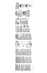
6-2013 Version 3.0 icreasePRO Creaser Operators Manual WWW.MBMCORP.COM 800-223-2508 TABLE OF CONTENTS SPECIFICATIONS…………………………………………………………………………………………….1a SAFETY PROCEDURES/CARE & MAINTENANCE.………………………………………………….1b COMPONENT IDENTIFICATION…………………………………………………………………………2 TOUCH SCREEN CONTROLLER ………………….………………………………………………….3 Crease Mode...................………………………………………….…….…………4 Transport Operation…………………………….……………………….……….……5 Programming for Crease Mode..………..…………………...............................……….5 Half Fold......................................................................................5 Tri-fold................................................................................………6 Z Fold.........................................................................................6 Letter Fold...................................................................................6 Roll Fold......................................................................................6 Gate Fold.....................................................................................7 Double Gate..................................................................................7 Double Parallel...............................................................................7 Perfect Bind Double Hinge...............................................................7 Perfect Bind Single Hinge...............................................................8 Perfect Bind No Hinge....................................................................8 Custom Crease Setups...................................................................8 Saving/Recalling Custom Jobs..........................................................9 Micro Adjusting the Crease Position...................................................9 DELIVERY TRAY ASSEMBLY…………………………………………………………………………….10 FEED TABLE ASSEMBLY……………………………………………………………………………….10 Adjusting Feed Rail………..……………………………………………….……..…11 Loading the Feeder…………………………………………………………………..11 Feeding Notes…………………………………………………………………………11 Checking the Sensor…………………………………….…………………………..11 Perf Shaft & Strike Plate……………………………………………………………18 Removing the Perf Shaft to Change Configurations………………………18 Folding Direction of Paper…………………………………………………………12 RAC System (Rotary Actuated Creasing) Assembly……………………………………….12 Adjusting RAC rollers (depth of crease)……………………………………..13 Changing Lower Crease Die……………………………………………………...14 TROUBLESHOOTING………………………………………………………………………………………..…15 ELECTRICAL REQUIREMENTS AND SPECIFICATIONS Power Requirement: 110/220V, 50-60 HZ, AC, Circuit Protection: 3 AMP Circuit Breaker NOTE: Older buildings, overloaded lines, and bad grounds can affect the operation of your icreasePRO. A dedicated line is best. OPERATING SPEEDS MODE TRANSPORT SPEED (Feet per Sec.) Crease Mode 2.0 8.5x11 Sheet(est) 5 ½” Sheet(est) 2000 2500 SPECIFICATIONS Net Weight: Overall Dimensions: Min. Sheet Size: Max. Sheet Size: IcreasePRO…………………………………………… 50 lbs …………………………………………………..…………22 3/4”Lx41”Wx10”H ………………………………………………………………3”x5” ………………………………………………………………13”x19”-36”* *NOTE: The icreasePRO is capable of handling many types of applications above and beyond the standard specifications. It is possible to feed quite a variety of jobs, from 36” sheets to die cut stocks. However, the performance of the icreasePRO on these special applications is directly related to the experience of the operator. 1a SAFETY PROCEDURES BEFORE USE: • Read through the owner’s manual. Follow instructions CAREFULLY. • NEVER use a wet area. Electric shock could occur. • Use a GROUNDED outlet and a GROUNDED circuit. Do not use ungrounded equipment on the same circuit. • Always use a dedicated line. DO NOT use with line splitting surge protector. DURING USE: • Keep fingers and hands away from creasing bar and rubber rollers. • Keep cords clear of moving parts. AFTER USE: • Turn off machine at the cover, then unplug the main power cord. This will prevent damage to your machine by power/voltage spikes. • To unplug cords, always grasp the plug body, never pull on cords to disconnect. Wire fatigue and possible shock could result from improper disconnect procedures. BE ALERT! BE CAREFUL! CARE AND MAINTENANCE The icreasePRO is a precision machine. It is very important to keep it free of excessive dust, dirt and foreign matter. We recommend that you keep the machine covered when not in use. BEARINGS: The icreasePRO uses sealed roller bearings. Sealed roller bearings and are designed to be self lubricating, however dirt and dust can get into them causing clogging and dirt build up It is recommended to occasionally oil the sealed roller bearings under heavy use. STRIKE DIE: The groove in the lower die should be cleaned periodically using a toothbrush to remove any dirt or build up. SENSOR EYE: Clean the lower reflector tape located on the base plate of the machine. Dust will cause the beam to not reflect correctly. Clean when necessary. REMOVEABLE SCREWS: When these show signs of wear or stripping, replace as soon as possible. If these strip or hollow out they can be costly to remove. If you do keep icreasePRO clean and in top condition, it will give you years of service. 1b COMPONENT IDENTIFICATION Feed Table Assembly Feed Rail Assembly Crease Bar Paper Stop Touch Screen Delivery Tray REFERENCES Touch Screen Feed Table Assembly Delivery Tray Crease Bar (RAC) Pg. Pg. Pg. Pg. 2 3 10 10 12 icreasePRO TOUCH SCREEN CONTROLLER 1 2 3 MBM Corporation 800-223-2508 THE TOUCH SCREEN CONSISTS OF: 1. MBM Logo and Service Access 2. Start Button 3. Serial Number Touch Screen Operation When the machine is turned on the display may take up to 7 seconds for the home screen to display. There is a screen saver that will turn the display off if the machine is not touched within 30 minutes. The power light will stay illuminated letting you know the machine is still on. MBM logo and Service Access If the logo is pressed a password screen is displayed. This is for factory and service access only. This Screen is for internal use only. The password is not given out. 3 Crease mode Crease mode is used to apply a Compression Crease/Score to a piece of paper. In this mode there are several Automatic Setup selections or you can do a custom selection and enter the distance in mm. Crease selections include half, tri-fold, z fold, letter fold, roll fold, gate fold, double gate, double parallel, 3 perfect bind selections. 4 TRANSPORT OPERATION • The Run Button will start the Transport in any given mode. Press it again to stop the transport. Each Mode has a timeout feature to preserve the life of the machine. • A document may be slowly advanced through the transport by pushing and holding one of these buttons. EXAMPLE: • The motor should advance transport at slow speed and stop whenever finger is lifted. Controls on-off function of motor. EXAMPLE: Machine will run at mode and speed previously selected. • Machine will stop. PROGRAMMING FOR CREASE MODE Half Fold: Press the Half Image> Start Measuring > Physically Run a sheet through the machine for the sensor to measure > Accept > Run. EXAMPLE: 5 Tri-Fold: Press the Tri-Fold Image > Start Measuring > Physically Run a sheet through the machine for the sensor to measure > Accept > Run. EXAMPLE: Z Fold: Press the Z Fold Image > Start Measuring > Physically Run a sheet through the machine for the sensor to measure > Accept > Run. EXAMPLE: Letter Fold: Press the Letter Image > Start Measuring > Physically Run a sheet through the machine for the sensor to measure > Accept > Run. EXAMPLE: Roll Fold: Press More > Roll Image > Start Measuring > Physically Run a sheet through the machine for the sensor to measure > Accept > Run. EXAMPLE: 6 Gate Fold: Press More > Gate Image > Start Measuring > Physically Run a sheet through the machine for the sensor to measure > Accept > Run. EXAMPLE: Double Gate Fold: Press More > Double Gate Image > Start Measuring > Physically Run a sheet through the machine for the sensor to measure > Accept > Run. EXAMPLE: Double Parallel Fold: Press More > Double Parallel Image > Start Measuring > Physically Run a sheet through the machine for the sensor to measure > Accept > Run. EXAMPLE: Perfect Bind Double Hinge: Press More > Perfect Binding Score Image > Enter The Book Thickness > Double Hinge Image > Start Measuring > Physically Run a sheet through the machine for the sensor to measure > Accept > Run. EXAMPLE: 7 Perfect Bind Single Hinge: Press More > Perfect Binding Score Image > Enter The Book Thickness > Single Hinge Image > Start Measuring > Physically Run a sheet through the machine for the sensor to measure > Accept > Run. EXAMPLE: Perfect Bind No Hinge: Press More > Perfect Binding Score Image > Enter The Book Thickness > No Hinge Image > Start Measuring > Physically Run a sheet through the machine for the sensor to measure > Accept > Run. EXAMPLE: Custom Crease Job: Press Custom > Enter In Distance For each Crease in mm > Accept > Run. 8 Saving Custom Crease Jobs: Press Custom > Enter In Distance For each Crease in mm > Save > Select Position to save in 1, 2, 3, or 4. Recalling Custom Crease Jobs: Press Custom > Recall > Accept > Run. Micro Adjusting the Crease Position: Press the adjust button from the run screen. You can micro adjust each crease by pressing the arrow keys each direction. Each press will adjust by 1/13th of a mm. Each Adjustment is relative to the one before it so if you adjust crease 1 by 3 clicks it will also move all the creases after it 3 clicks. You would then need to adjust them back 3 clicks each. 9 FEED TABLE ASSEMBLY Mount Notch Feed rail on non operator side DELIVERY TRAY ASSEMBLY INSTALLING THE DELIVERY TRAY The delivery tray is held in place with 2 dowel pins on each frame. Position the tray to slide it under the 2 dowel pins and rest the angle stop up. 10 ADJUSTING THE FEED RAIL The feed rail on your icreasePRO is designed to adjust easily in case of a problem with crooked feeding. By loosening the feed rail screw and nut on the front or rear of the rail you can move the rail for sqaureness. LOADING THE FEEDER Take one piece of paper and slide it along the rail ensuring it is square along the entire rail. Gently slide the paper until the rollers take the sheet then release. Make sure to allow the sheet to run completely through the machine before running the next sheet. Repeat until job is complete. FEEDING NOTES • When set properly, the feed is very efficient and flexible. When neglected it can become very frustrating to run even the simplest job. The adjustments previously discussed are very important. • The icreasePRO is capable of running 20lb. single sheets up to 16 point. It is also very capable of handling gloss, coated, and even laminated stocks. Its flexibility is directly related to the operator’s experience. To clean the rubber rollers, use only water on a clean cloth. Wipe the rollers in the direction of the ribbing while turning them by hand. • CHECKING THE SENSORS 1. Turn machine power on and allow screen to turn on 2. There should be 2 lights on the sensor a green indicating power is getting to the sensor and orange that is the reflecting signal. If both lights are not on there is a problem and must be fixed before you are able to run. 3. Make sure the sensor reflector tape is located on the base plate and the red beam from the sensor is hitting the tape. If not remove the non operator side cover and loosen the screw on the sensor bracket and adjust the beam until it is on the tape and both lights are on. 4. If all above steps work correctly sensor is working properly, if not, contact the MBM Corporation service department. 11 FOLDING DIRECTION OF PAPER There is a correct and incorrect way to fold a creased paper. Following the diagram below will show you the correct direction the paper should be folded. RAC System (Rotary Actuated Creasing) Assembly 12 ADJUSTING THE RAC ROLLERS The RAC rollers are set from the factory and it is NOT recommended to make any adjustments to this without consulting with MBM’s tech-support department. Should an adjustment be necessary, please follow the steps below. This adjustment is used to adjust the pressure of the crease. Start by loosening both lock screws located on each side of the silver brackets shown below. Now adjust using the adjust screw located on he bottom of each bracket. Do this for both sides so you have an even crease. This allows very slight adjustments of the lower support bar. Once the adjustment to the bar has been made, tighten the lock screw. Failure to tighten the lock screw will result in the lower support bar moving down each time the crease bar is fired. Be very careful not to adjust to much or the crease bar will not rotate all the way though. This will cause the crease motor to over amp and pull the power from the PLC and the HMI resulting in the bar being stuck in the down position. If this happens turn the power off to the machine, adjust the lower support down, turn the machine back on and press the last job then the crease test button. IF this does not fix the problem call the MBM Corporation service department. Lock Screw Adjust Screw 13 CHANGING THE LOWER CREASE DIE The Lower crease die can easily be changed to accommodate thicker stocks(.01 or thicker) by removing the delivery tray, remove the clear cover, rotate the 2 lock pin brackets. Slide the bar out and flip it over to use the wider die channel. Lock Pin Brackets 14 TROUBLE SHOOTING • • • • • • • POWER DOES NOT TURN ON 1. Check fuse on side cover. 2. Check outlet for power. POWER TURNS ON BUT HMI DOES NOT LIGHT UP 1. Check fuse on side cover. 2. Make sure the green lights through the slots in the back panel are on. If not Check outlet power. 3. Check wiring to the plc and hmi. TRANSPORT “LOCKS UP” AFTER CREASING 1. Check pulleys to make sure they are securely tightened on shafts. 2. Check to see that the transport turns freely (oil when necessary). SHEETS NOT FEEDING STRAIGHT 1. Align feed rail “check for squareness”. This can be checked by the lead edge of the paper feeding into the machine should line up with the front edge of the feed plate. 2. Check for paper curl. CREASE NOT REGISTERING ON SHEET 1. Clean all Rubber Rollers 2. Check deflector position. 3. Check all pulleys to make sure they are securely tensioned on shafts. 4. Check to see that machine transport turns freely. CREASE APPEARS WEAK 1. Crease bar not level. 2. Not enough pressure, adjust RAC rollers with height adjustment screw. 3. Too much pressure, motor cannot make full stroke. 4. Support bar not tightened properly on bracket. CREASE BAR DOES NOT ROTATE 1. Crease bar set too high, cannot make full stroke. 2. Crease bar is dirty. Clean with damp cloth and wipe clean. 3. Verify red light on creaser plc at Y4 is firing on and off. 15