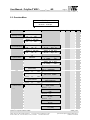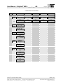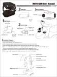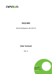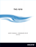
1
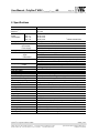
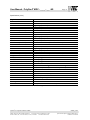
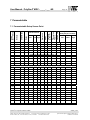
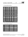
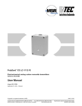
PolyGard MGC - 4 - 5 _ _ - _ _ US MGC - 8 - _ _ _ - _ _ US MGC - 16 - _ _ _ - _ _ US MGC - 24 - _ _ _ - _ _ US Gas monitoring, control and alarm system User Manual September, 2003 PolyGard is a registered trademark of MSR Phone: (858) 578-7887 & (888) GO INTEC Fax (858) 578-4633 & (888) FX INTEC INTEC Controls, Inc., P.O. Box 12506, La Jolla, CA 92039 www.inteccontrols.com GAMGC_01US Specification subject to change without notice. Printed in USA 030918 User Manual - PolyGard® MGC - _ _ _ - _ _ -US Page 2 Gas monitoring, control and alarm system 1 Description....................................................................................................................................3 2 Operating Instrucion MGC ...........................................................................................................4 2.1 2.2 3 Setting / Change Parameter or value.....................................................................................5 Overview Menu .....................................................................................................................6 Describtion Menus........................................................................................................................9 3.1 Main page Menu....................................................................................................................9 3.2 Reading sensor (Main Menu).................................................................................................9 3.3 Threshold setup (Main Menu) ..............................................................................................10 3.4 System status (Main Menu) .................................................................................................11 3.4.1 Status SP (Sub Menu 1)...................................................................................................11 3.4.2 Status Relay (Sub Menu 1) ..............................................................................................12 3.4.3 Error System (Sub Menu 1) ..............................................................................................13 3.4.3.1 Error Reset ...................................................................................................................14 3.4.4 System Reset (Sub Menu 1) ............................................................................................15 3.5 System setup (Main Menu) ..................................................................................................16 3.5.1 Applicats setup (Sub Menu 2) ..........................................................................................16 3.5.1.1 Config System..............................................................................................................16 3.5.1.2 Service Mode (Sub Menu 2) .........................................................................................16 3.5.1.3 Power ON delay time (Sub Menu 2) .............................................................................17 3.5.1.4 Response time (Sub Menu 2) .......................................................................................17 3.5.1.5 New Password level 1(Sub Menu 2) .............................................................................17 3.5.2 Setup Sensor Point (Sub Menu 1) ....................................................................................18 3.5.3 Setup Relay (Sub Menu 1) ...............................................................................................21 3.5.4 Setup DI (Sub Menu 1) ....................................................................................................22 3.5.5 Setup Date and Time (Sub Menu 1) .................................................................................23 3.5.6 Setup Analog Output (Sub Menu 1)..................................................................................23 4 Mounting / Electrical Connection ..............................................................................................24 4.1 4.2 Mounting .............................................................................................................................24 Electrical Connection...........................................................................................................24 5 Start-up operation.......................................................................................................................25 6 Specifications .............................................................................................................................26 7 Parametertable ............................................................................................................................28 7.1 7.2 7.3 8 Notes and General Information..................................................................................................30 8.1 8.2 8.3 8.4 8.5 9 Parametertable Setup Sensor Point.....................................................................................28 Parametertable Setup Relay................................................................................................29 Parametertable Configuration..............................................................................................29 Intended product application................................................................................................30 Installers` responsibilities.....................................................................................................30 Maintenance........................................................................................................................30 Limited warranty ..................................................................................................................30 Return instructions...............................................................................................................30 Wiring Diagramm and Dimension ..............................................................................................31 PolyGard is a registered trademark of MSR Phone: (858) 578-7887 & (888) GO INTEC Fax (858) 578-4633 & (888) FX INTEC INTEC Controls, Inc., P.O. Box 12506, La Jolla, CA 92039 www.inteccontrols.com GAMGC_01US Specification subject to change without notice. Printed in USA 030918 User Manual - PolyGard® MGC - _ _ _ - _ _ -US Page 3 Gas monitoring, control and alarm system 1 Description Stand alone, wall mounted, mirco procssor based multi-point analog electronic control System for various gas, temperature and humidity detection, control and alarm. To control and alarm maximum 24 Sensor Point (SP) for toxic- combustible- refrigerant- gases, temperature and humidity. Any combination of the AT-11/33/35/7700 gas transmitter and/or other Transmitter with 4 to 20 mA signal can be hooked up to the control unit. For every Sensor Point are 3 alarm thresholds integrated. Every alarm threshold can be assigned to one or more of the maximum 18 potential free relays. The controller can interface via 4 to 20 mA outputs to any compatible electronic analog control, DDC/PLC control or automation system. PolyGard is a registered trademark of MSR Phone: (858) 578-7887 & (888) GO INTEC Fax (858) 578-4633 & (888) FX INTEC INTEC Controls, Inc., P.O. Box 12506, La Jolla, CA 92039 www.inteccontrols.com GAMGC_01US Specification subject to change without notice. Printed in USA 030918 User Manual - PolyGard® MGC - _ _ _ - _ _ -US Page 4 2 Operating Instrucion MGC The complete configuration, parameterization and service is made via keypad user interface in combination with the display screen. Security is provided via two password levels. The lower level password, level 1, allows the override or to reset system status functions. The upper level password, level 2, allows all pogramming and override functions. Default Password lower level = 1,2,3,4 Keypad User Interface “DBT” INTEC - Control 08.15.03 1.22 pm ESC LED “Yellow” flashes at Low, Med or High Threshold LED “Red” flashes at System/Sensor Failed ⇔⇐ Scrolls down & up in Main menu and Sub menus; increases or decreases a value. ∧∨ Navigates through menus on the same level; moves of cursor inputing data. ↵ Enter sub menus; issues system reset; stores security password. ESC Exits programming and saves settings; returns to the previous menu level. PolyGard is a registered trademark of MSR Phone: (858) 578-7887 & (888) GO INTEC Fax (858) 578-4633 & (888) FX INTEC INTEC Controls, Inc., P.O. Box 12506, La Jolla, CA 92039 www.inteccontrols.com GAMGC_01US Specification subject to change without notice. Printed in USA 030918 User Manual - PolyGard® MGC - _ _ _ - _ _ -US Page 5 2.1 Setting / Change Parameter or value Example: Change the Low Threshold for Sensor Point 1 • Open Window Threshold for Sensor Point 1 SP#01 CO C ppm Lo 50 Me 75 ↵ Yes Security Code level is acting? No SP#01 CO C ppm ENTER PASS * * * * • • • • The Cursor stand at the first segment. With ⇔⇐ scroll the password number. With ∨ scroll the Cursor to the next segment. For segment 3 and 4 it was the same procedure. ESC ↵ OK Acknowledgement the Password If Password? False SP#01 CO C ppm FALSE PASSWORD SP#01 CO C ppm Lo 50 Me 75 • The Cursor stand at the first segment that can be changed. • With ⇔⇐ change this segment for the Parameter. • With ∧ ∨ select the next segment do you want change. ESC Load the changed Parameter PolyGard is a registered trademark of MSR Phone: (858) 578-7887 & (888) GO INTEC Fax (858) 578-4633 & (888) FX INTEC INTEC Controls, Inc., P.O. Box 12506, La Jolla, CA 92039 www.inteccontrols.com GAMGC_01US Specification subject to change without notice. Printed in USA 030918 User Manual - PolyGard® MGC - _ _ _ - _ _ -US Page 6 2.2 Overview Menu Main Page INTEC Controls 08.15.03 01:20 pm ↵ Main Menu Sub Menu 1 ESC ↵ Reading sensor Sub Menu 2 SM 3 SM 4 SM 5 SM 6 SP#01 C CO ppm 10 5 000 ⇔⇐ See 3.2 SP#24 C CO ppm 10 5 000 ⇔⇐ ESC Threshold setup ↵ SP#01 C CO ppm Lo 50 Me 75 ∨ ∧ SP#01 C CO ppm Hi 75 Hys 15 ⇔⇐ See 3.3 ⇔⇐ SP#24 C CO ppm Lo 50 Me 75 ⇔⇐ ↵ ESC System status See 3.4 SP#24 C CO ppm Hi 75 Hys 15 ↵ Status SP SP#01 CO C ppm A Ready 000 ⇔⇐ SP#24 CO C ppm A Ready 000 ⇔⇐ See 3.4.1 ESC ⇔⇐ See 3.4.2 ⇔⇐ ↵ DIO1 => DIO2 => Status Relay ESC ↵ System ERROR See 3.4.3 ⇔⇐ ESC ↵ System RESET See 3.4.4 System Setup See 3.5 ESC See 3.1 ⇔⇐ Applicats setup See 3.5.1 ESC ↵ 000000000 000000000 #01 ERR#01 07.20 SP< 2 mA SP#03 System Reset Reset Confirmed System CONFIG MGC XX/XX See 3.5.1.1 ⇔⇐ Service OFF See 3.5.1.2 ⇔⇐ Power ON delay 20 sec. See 3.5.1.3 ⇔⇐ Response Time 20 sec See 3.5.1.4 ⇔⇐ Password **** (1234) PolyGard is a registered trademark of MSR Phone: (858) 578-7887 & (888) GO INTEC Fax (858) 578-4633 & (888) FX INTEC INTEC Controls, Inc., P.O. Box 12506, La Jolla, CA 92039 www.inteccontrols.com GAMGC_01US Specification subject to change without notice. Printed in USA 030918 User Manual - PolyGard® MGC - _ _ _ - _ _ -US Page 7 See 3.5.1.5 PolyGard is a registered trademark of MSR Phone: (858) 578-7887 & (888) GO INTEC Fax (858) 578-4633 & (888) FX INTEC INTEC Controls, Inc., P.O. Box 12506, La Jolla, CA 92039 www.inteccontrols.com GAMGC_01US Specification subject to change without notice. Printed in USA 030918 User Manual - PolyGard® MGC - _ _ _ - _ _ -US Page 8 Continuation Overview Menu M. M. Sub M.1 ESC SP setup Sub Menu 2 ↵ Sub Menu 3 ∨ SP#01 CO C ppm A CO CV nnn 0 ∧ Sub Menu 4 ∨ SP#01 CO C ppm L-M-H- 250 1800 ∧ Sub Menu 5 ∨ SP#01 100000000 LOW 000000000 ∧ Sub Menu 6 ∨ SP#01 000000000 MED 000000000 ∧ SP#01 001000001 High 000000000 See 3.5.2 ⇔⇐ ⇔⇐ ⇔⇐ ⇔⇐ ⇔⇐ ⇔⇐ SP#24 CO C ppm A CO CV nnn 0 SP#24 CO C ppm L-M-H- 250 1800 SP#24 000000000 LOW 000000000 SP#24 000000000 MED 000000000 SP#24 000000000 High 000000000 ESC Relay setup ↵ R#01 ON OFF 0 s01 s01 ⇔⇐ See 3.5.3 ⇔⇐ ESC DI setup R#18 ON OFF 0 s01 s01 - ↵ DI-01 000000000 Horn 000000000 See 3.5.4 ⇔⇐ ⇔⇐ DI-04 000000000 Horn 000000000 ESC ↵ Date/ Time Date/Time 08.15.03 Sa See 3.5.5 ⇔⇐ ⇔⇐ Date/Time 01 : 20 pm ESC AO setup See 3.5.6 ↵ Calibration AO#01 4mA 42 20mA 144 ⇔⇐ Function AO#01 Ave ⇔⇐ Calibration AO#02 4mA 42 20mA 144 ⇔⇐ Function AO#02 Ave PolyGard is a registered trademark of MSR Phone: (858) 578-7887 & (888) GO INTEC Fax (858) 578-4633 & (888) FX INTEC INTEC Controls, Inc., P.O. Box 12506, La Jolla, CA 92039 www.inteccontrols.com GAMGC_01US Specification subject to change without notice. Printed in USA 030918 User Manual - PolyGard® MGC - _ _ _ - _ _ -US Page 9 3 Describtion Menus 3.1 Main page Menu In the normal operation Mode the main page displays the time and date. In the Fault Status the main page display the last fault with plain text. Main Page / Normally Main page with Fault Status INTEC Controls 08.15.03 1:20 pm #01 ERR#01 08.15 SP < 2mA SP09 3.2 Reading sensor (Main Menu) Display the gas value and threshold status for every Sensor Point. SP#XX C CO ppm 10 5 000 ⇔ ⇐ (Change window Sensor Point) Window Reading sensor legend Symbol Describtion Function SP#XX Sensor Point number C/A Operating Mode Display CO ppm 10 5 Gas type Gas unit Current value Display Average value Display 000 (Lo, Me, Hi) Threshold Status (Lo, Me, Hi) ***** Not Active Sensor Point failure Sensor Point is not acting (1 to max. 241) C = current value mode A = average value mode See “Select Gas type” (3.5.2) See “Select Gas type” (3.5.2) e.g.: 10 ppm e.g.: 5 ppm 0 = OFF 1 = ON Signal < 2 mA 1 Dependent on the configuration of the System. PolyGard is a registered trademark of MSR Phone: (858) 578-7887 & (888) GO INTEC Fax (858) 578-4633 & (888) FX INTEC INTEC Controls, Inc., P.O. Box 12506, La Jolla, CA 92039 www.inteccontrols.com GAMGC_01US Specification subject to change without notice. Printed in USA 030918 User Manual - PolyGard® MGC - _ _ _ - _ _ -US Page 10 3.3 Threshold setup (Main Menu) • Display and Setting the Threshold Low, Med, High and Hysteresis for each Sensor Point. (Setting and Change with Security level 2) SP#XX CO C ppm Lo 50 Me 75 ⇔ ⇐ ∨ ∧ SP#XX CO C ppm Hi 100 Hys 15 (Change window Sensor Point) Window Threshold setup legend Symbol Describtion SP#XX Sensor Point number C/A Operating Mode Display C CO ppm Lo Me Hi Hys Gas type Gas unit Threshold level 1 (Low) Threshold level 2 Med) Threshold level 3 (High) Hysteresis level CO ppm 50 ppm 75 ppm 100 ppm 15 ppm 1 Default Function (1 to max. 241) C = current value mode A = average value mode See “Select Gas type” (3.5.2) See “Select Gas type” (3.5.2) e.g.: e.g.: e.g.: e.g.: Dependent on the configuration of the System. PolyGard is a registered trademark of MSR Phone: (858) 578-7887 & (888) GO INTEC Fax (858) 578-4633 & (888) FX INTEC INTEC Controls, Inc., P.O. Box 12506, La Jolla, CA 92039 www.inteccontrols.com GAMGC_01US Specification subject to change without notice. Printed in USA 030918 User Manual - PolyGard® MGC - _ _ _ - _ _ -US Page 11 3.4 System status (Main Menu) 3.4.1 Status SP (Sub Menu 1) • • • Display status of each Sensor Point. Manual override capability for threshold levels3. (Security level 1) Acknowledged the latching Status for each Threshold, when the latching function was setting. (Security level 1) SP#XX CO C ppm A Ready 110 ⇔⇐ (Change window Status Sensor Point) Window Status Sensor Point (SP) legend Symbol Describtion SP#XX Sensor Point C/A CO ppm A/N Ready/Error Setting Status Function Operating Mode Display Gas type Gas unit Sensor point active - not active (1 to max. 241) C = current value mode A = average value mode See “Select Gas type” (3.5.2) See “Select Gas type” (3.5.2) A = Sensor Point active N = Sensor Point not active Status Sensor Point Ready = Sensor Point OK Error2 = Failure by Sensor Point 110 (Lo, Me, Hi) Threshold status L H A R Q 0 = Threshold Status OFF (by automatic Mode) 1 = Threshold Status ON (by automatic Mode) L = Set Threshold Status manual OFF3 H = Set Threshold Status manual ON3 A = Set Threshold Status to automatic Mode R = Threshold latching Status4, Status can be Acknowledged4 Q = Threshold latching function, acknowledged Alarm 1 Dependent on the configuration of the System. Fault Handling. See 3.4.3.1. 3 The operating mode manual has priority before the operating mode automatic. 4 Activate latching Mode Threshold. See 3.5.2 2 PolyGard is a registered trademark of MSR Phone: (858) 578-7887 & (888) GO INTEC Fax (858) 578-4633 & (888) FX INTEC INTEC Controls, Inc., P.O. Box 12506, La Jolla, CA 92039 www.inteccontrols.com GAMGC_01US Specification subject to change without notice. Printed in USA 030918 User Manual - PolyGard® MGC - _ _ _ - _ _ -US Page 12 3.4.2 Status Relay (Sub Menu 1) • • • Display the status for each relay. Manual override capability for each Relay.1 (Security level 1) Acknowledged the latching Status for each Relay, when the latching function was setting. (Security level 1) DIO 1 => 000000000 DIO 2 => 000000000 Window Satus Relay legend Symbol Describtion DIO - 1 DIO - 2 Status Relay module 1 Status Relay module 2 1 Relay No to 9 000000000 000000000 Status Relay number 10 to 18 Relay No Setting Status Function Relay 1 to 9 (DIO-4/9 no. 1) L H A R Q 1 2 Relay 10 to 18 (DIO-4/9 no. 2) 0 = Relay Satus OFF (by automatic Mode) 1 = Relay Status ON (by automatic Mode) L = Set Relay manual OFF1 H = Set Relay manual ON1 A = Set Relay Status to automatic Mode R = Relay latching Status2, Status can be Acknowledged2 Q = Relay latching function, acknowledged Relay The operating mode mnual has priority before the operating mode automatic. Activate latching Mode Relay. See 3.5.3 PolyGard is a registered trademark of MSR Phone: (858) 578-7887 & (888) GO INTEC Fax (858) 578-4633 & (888) FX INTEC INTEC Controls, Inc., P.O. Box 12506, La Jolla, CA 92039 www.inteccontrols.com GAMGC_01US Specification subject to change without notice. Printed in USA 030918 User Manual - PolyGard® MGC - _ _ _ - _ _ -US Page 13 3.4.3 Error System (Sub Menu 1) • • Display the fault list. Reset Error. (Security level 1) #01 ERR#01 07.20 SP < 2mA SP#03 ⇔⇐ Next window of Fault list Fault list legend Symbol Describtion Function #01 Numeric order of Fault list (1 to max. 121) ERR#01 Fault type 01 = Sensor Point fault 02 = Bus fault to AI8 - module 03 = Bus fault to DIO - module 07.20 Fault date SP < 2mA SP < 2 mA – SP#XX2 (1 to max. 243) Fail AI8 – XX3 (1 to max. 33 ) Fail DIO – XX3 (1 to max. 23) Plain text Fault 1 In the Menu the last 12 Fault are listed. Unit number. 3 Dependent on the configuration of the System. 2 Fault Describtion Trouble Reason Solution SP < 2 mA Sensor Point not connected. Sensor Point wrong connected (Polarity exchanges). Sensor Point cable break. Sensor Point defective / not calibrated. Check Sensor Point connection and polarity. Check cable. Check Sensor Point. Make Calibration. Fail AI8 Fail DIO System configuration not compatible to the connected modules. Addressing AI8 or DIO modules no correct. Bus Cable defective. Check System Configuration.1 Check module Adrressing.2 Check Bus cable. 3 1 See Menu “Config System” (3.5.1.1) See Field wiring Configuration (7) for AI and DIO Module. (Not Addressing by CGC module) 3 See internal wiring diagram 2 PolyGard is a registered trademark of MSR Phone: (858) 578-7887 & (888) GO INTEC Fax (858) 578-4633 & (888) FX INTEC INTEC Controls, Inc., P.O. Box 12506, La Jolla, CA 92039 www.inteccontrols.com GAMGC_01US Specification subject to change without notice. Printed in USA 030918 User Manual - PolyGard® MGC - _ _ _ - _ _ -US Page 14 3.4.3.1 Error Reset • Reset Error Status after the elimination of the defect with this procedure. (Security level 1) #01 ERR#01 07.20 SP < 2mA SP#03 ESC Main page with failure Status Change Menu level Readig Sensor ⇐ Threshold setup ⇐ System Status ESC Change Menu level Status SP ⇐ Status Relay ⇐ System ERROR ESC Change Menu level Plain text ↵ #01 ERR#XX 08.15 Error Reset ↵ PolyGard is a registered trademark of MSR Phone: (858) 578-7887 & (888) GO INTEC Fax (858) 578-4633 & (888) FX INTEC INTEC Controls, Inc., P.O. Box 12506, La Jolla, CA 92039 www.inteccontrols.com Error Reset, if Fault eliminated. GAMGC_01US Specification subject to change without notice. Printed in USA 030918 User Manual - PolyGard® MGC - _ _ _ - _ _ -US Page 15 3.4.4 System Reset (Sub Menu 1) • In this Menu Reset all System fault, latching Threshold and latching Relay. System RESET Reset Confirmed PolyGard is a registered trademark of MSR Phone: (858) 578-7887 & (888) GO INTEC Fax (858) 578-4633 & (888) FX INTEC INTEC Controls, Inc., P.O. Box 12506, La Jolla, CA 92039 www.inteccontrols.com GAMGC_01US Specification subject to change without notice. Printed in USA 030918 User Manual - PolyGard® MGC - _ _ _ - _ _ -US Page 16 3.5 System setup (Main Menu) 3.5.1 Applicats setup (Sub Menu 2) 3.5.1.1 Config System • In this menu the configuration of the System appropriate the connected input / output modules. (Security level 2) System CONFIG MGC 24/18 ⇔⇐ Next Type Window System Config legend Symbol Types MGC 24/18 MGC 24/09 MGC 16/18 MGC 16/09 MGC 08/18 MGC 08/09 MGC 04/05 MGC 24/18 1 Connected Hardware modules 3 – AI-81-module; 2 – DIO-4/92-module 3 – AI-81-module; 1 – DIO-4/92-module 2 – AI-81-module; 2 – DIO-4/92-module 2 – AI-81-module; 1 – DIO-4/92-module 1 – AI-81-module; 2 – DIO-4/92-module 1 – AI-81-module; 1 – DIO-4/92-module 1 – CGC3-module AI-8 module: 8 x analog Input, 4 to 20 mA, for connect max. 8 Sensor Point. 2 analog output, 4 to 20 mA.. 2 DIO-4/9 module: Output module with 9 potentialfree relay, 4 digital Input. 3 CGC module: 4 x analog Input, 4 to 20mA, for connect max. 4 Sensor Point. 5 output with potentialfree relay. 1 analog output, 4 to 20 mA. 3.5.1.2 Service Mode (Sub Menu 2) • Being in Service Mode will allow service personnel to simulate warning / alarm Threshold values without relays being set. • The Service Mode will reset automatically after 60 minutes to normal operation status if not changed manual. (Security level 2) Service OFF Window Service Mode legend Symbol Setting Status Function OFF OFF Normal operation Mode ON Service operation Mode PolyGard is a registered trademark of MSR Phone: (858) 578-7887 & (888) GO INTEC Fax (858) 578-4633 & (888) FX INTEC INTEC Controls, Inc., P.O. Box 12506, La Jolla, CA 92039 www.inteccontrols.com GAMGC_01US Specification subject to change without notice. Printed in USA 030918 User Manual - PolyGard® MGC - _ _ _ - _ _ -US Page 17 3.5.1.3 Power ON delay time (Sub Menu 2) • Change Power ON delay time (Security level 2) Power ON delay 20 sec. To prevent the measurement of wrong analog input signals during power on time, this time disables calculation of analog values. After the end of this time, the system works in normal operation mode. Recommended Time = 30 sec. 3.5.1.4 Response time (Sub Menu 2) • Set Response time (Security level 2) Response Time 20 sec. After the end of this time, the horn relay is activated again if the alarm is set still. Example: DI 1 = Reset Horn Relay 3 = Horn Relay (activates through High alarm SP 1 ) High ON alarm OFF Gas Concentration -larger Response Time - smaller then Threshold Response Time Horn ON (Relay 3) OFF Reset about DI 1 ON OFF 3.5.1.5 New Password level 1(Sub Menu 2) • Change the Password for Security level 1 (Security level 2) Password **** (1234) With password for level 2 the customer password level 1 can be changed. PolyGard is a registered trademark of MSR Phone: (858) 578-7887 & (888) GO INTEC Fax (858) 578-4633 & (888) FX INTEC INTEC Controls, Inc., P.O. Box 12506, La Jolla, CA 92039 www.inteccontrols.com GAMGC_01US Specification subject to change without notice. Printed in USA 030918 User Manual - PolyGard® MGC - _ _ _ - _ _ -US Page 18 3.5.2 Setup Sensor Point (Sub Menu 1) • In the menu the definition of the parameters and the assignment of the Thresholds to the relays for every Sensor Point occur. (Security level 2) SP#XX CO C ppm A CO CV nnn 0 ∨ ∧ SP#XX CO C ppm L-M-H- 250 1800 ∨ ∧ SP#XX LOW 000000000 000000000 ⇔⇐ ∨ ∧ SP#XX MED ∨ ∧ SP#XX High 000000000 000000000 Next Sensor Point 000000000 000000000 Window Sensor Point legend Symbol Describtion Function SP#XX Sensor Point number C/A Operating Mode Display CO ppm Gas type Gas unit (1 to max. 241) C = current value mode A = average value mode See “Select Gas type” (3.5.2) See “Select Gas type” (3.5.2) 1 Dependent on the configuration of the System. Select Sensor Point Status Symbol Setting Status Function A A = Sensor Point active N N = Sensor Point non active Activate the connected Sensor Point for control Mode. A Select Gas type Symbol CO Setting Gas type CO NO NO2 NH3 O2 Ex R11 R123 R134A R22 TEM RH Unit Gas ppm ppm ppm ppm %v/v %LEL ppm ppm ppm ppm °F %RH Carbon monoxide Nitric monoxide Nitric dioxide Ammonia Oxigen Combustible Gas Refrigerant Gas Refrigerant Gas Refrigerant Gas Refrigerant Gas Temperatue Humidity Select the Gas type for the connected Sensor Point PolyGard is a registered trademark of MSR Phone: (858) 578-7887 & (888) GO INTEC Fax (858) 578-4633 & (888) FX INTEC INTEC Controls, Inc., P.O. Box 12506, La Jolla, CA 92039 www.inteccontrols.com GAMGC_01US Specification subject to change without notice. Printed in USA 030918 User Manual - PolyGard® MGC - _ _ _ - _ _ -US Page 19 Select Control Mode Symbol Setting Control Mode Function CV CV = Current value mode1 AV AV = Average value mode2 CV 1 Current value Mode: alarms are set in dependence to Current value. Average value Mode: alarms are set in dependence to Average value. See also “Time factor to the calculating of the Average value” 2 Set Threshold by Sensor Point failure Symbol Setting Threshold at SP Fault Function n= L L= M M= H H= nnn (L M H) Set no Threshold at SP Fault Set Low Threshold at SP Fault Set Med Threshold at SP Fault Set High Threshold at SP Fault A failure at the Sensor Point activates the selecdet Threshold It can assigned one or more Threshold Assigning Sensor Point to analog output (AO) Symbol Connect SP to AO Function 0 0= 1 1= 2 2= 0 SP not assigned to AO SP assigned to AO 1 SP assigned to AO 2 The MGC has 2 analog output (AO) with 4 to 20 mA. Each AO can be assigned to one or more Sensor Point. The Sensor Point sends the current- or average value, in dependance of the operating mode, to the AO. Definition of the measuring range Symbol 250 Set Measuring Range Function 250 250 = Measuring range for CO Defindet the measuring range of the gas type. PolyGard is a registered trademark of MSR Phone: (858) 578-7887 & (888) GO INTEC Fax (858) 578-4633 & (888) FX INTEC INTEC Controls, Inc., P.O. Box 12506, La Jolla, CA 92039 www.inteccontrols.com GAMGC_01US Specification subject to change without notice. Printed in USA 030918 User Manual - PolyGard® MGC - _ _ _ - _ _ -US Page 20 Activate Latching Mode for Threshold Symbol Set Function Function L-M-H- + -= += Latching Function non active Latching Function active The latching mode can be activate for one or more Threshold. Example: Med Alarm with latching Function (L- M+ H-) Gas Concentration Gas Concentration -larger Display Status SP Threshold Med Reset in the Menu Status SP - smaller then Threshold 0 0 1 1 1 1 1 1 1 1 1 1 1 1 1 1 1 1 1 R R R R R R R 0 0 0 0 0 ON OFF ON OFF Time factor1 to the calculating of the Average value Symbol 1800 Set Time Function 1800 1800 = Time factor1 in sec. (half hour average value) 1 Time for building an average-value. Within this time-unit 10 values are saved and arithmetic average values are made out of then. Assigned Relay to Threshold1 Symbol SP#XX LOW 000000000 000000000 Relay No. 01 to 09 10 to 18 Assig Function 0 0= Threshold non assigned to Relay 1 1= Threshold assigned to Relay Here the assignment of the relay to the Threshold occurs. 1 It is the same Prozedure for Low- Med- and High- Threshold. It can assigned one or more Relay to each Threshold. Special feature MGC-4 The internal horn is at the aoutput 5, Relay 5, connected. PolyGard is a registered trademark of MSR Phone: (858) 578-7887 & (888) GO INTEC Fax (858) 578-4633 & (888) FX INTEC INTEC Controls, Inc., P.O. Box 12506, La Jolla, CA 92039 www.inteccontrols.com GAMGC_01US Specification subject to change without notice. Printed in USA 030918 User Manual - PolyGard® MGC - _ _ _ - _ _ -US Page 21 3.5.3 Setup Relay (Sub Menu 1) • Set parameters for each Relay. (Security level 2) R#XX 0 ON OFF s 01 s 01 ⇔⇐ Next Relay Window Setup Relay legend Symbol R#XX 1 Describtion Function Relay number (1 to max. 181) Dependent on the configuration of the System. Set Relay Mode Symbol Set Mode Function 0 0= 1 1= 0 Relay Mode de-energized Relay Mode energized (fail-safe) Selected the operating mode for each relay Set delay Time for ON and OFF Symbol ON s 1 OFF s 1 Set Time Function 1 to 9999 ON = Delay Time ON (sec.) 1 to 9999 OFF = Delay Time OFF (sec.) Set the delay Time for each relay Example: Relay 2 with Delay Time ON and OFF Med ON alarm OFF Relay 2 Display Status Relay 2 ON Gas Concentration -larger Delay Time ON - smaller then Threshold Delay Time OFF OFF 0 0 0 0 0 0 1 1 1 1 1 1 1 1 1 1 1 1 1 1 1 1 1 1 0 0 0 0 0 0 0 PolyGard is a registered trademark of MSR Phone: (858) 578-7887 & (888) GO INTEC Fax (858) 578-4633 & (888) FX INTEC INTEC Controls, Inc., P.O. Box 12506, La Jolla, CA 92039 www.inteccontrols.com GAMGC_01US Specification subject to change without notice. Printed in USA 030918 User Manual - PolyGard® MGC - _ _ _ - _ _ -US Page 22 Set latching Mode for Relay Symbol Set Function Function - -= + += _ Non latching Mode Latching Mode Example: Relay 2 with latching Function Relay 2 = Med Alarm Med ON alarm OFF Display Status Relay 2 Relay 2 Gas Concentration -larger - smaller then Threshold 0 0 1 1 1 1 1 1 1 1 1 1 1 1 1 1 1 1 1 R R R R R R R 0 0 0 0 0 ON OFF Reset in ON the Menu Status Relay OFF 3.5.4 Setup DI (Sub Menu 1) • Assigned Digital Input to Horn Relay for Reset Horn (Reset Horn with external pushbutton) (Security level 2) DI-XX Horn 000000000 000000000 ⇔⇐ Next DI Assigned Reset Horn legend Function: see Diagram response Time (3.5.1.4) Window Setup DI legend Symbol Set Reset Digital Input No (1 to 4) DI#XX DI#01 Horn Function 000000000 000000000 Relay No. 01 to 09 10 to 18 0 0= 1 1= Non Reset Horn Relay Reset Horn Relay * It is the same Prozedure for DI - 01 to DI – 04. It can assigned one or more Relay to every Digital Input. PolyGard is a registered trademark of MSR Phone: (858) 578-7887 & (888) GO INTEC Fax (858) 578-4633 & (888) FX INTEC INTEC Controls, Inc., P.O. Box 12506, La Jolla, CA 92039 www.inteccontrols.com GAMGC_01US Specification subject to change without notice. Printed in USA 030918 User Manual - PolyGard® MGC - _ _ _ - _ _ -US Page 23 3.5.5 Setup Date and Time (Sub Menu 1) • Setup Date and Time (Security level 1) Date / Time 08.15.03 Sa Setup Date ⇔⇐ Date / Time 01 : 20 pm Setup Time 3.5.6 Setup Analog Output (Sub Menu 1) • The MGC1 has 2 analog Output (AO) with 4 to 20 mA signal. Everyone AO can be assigned to one or more Sensor Point. The Sensor Point sends the current- or average value, in dependance of the operating mode, to the AO. (Security level 2) 1 The MGC 4 has 1 Analog Output • The hardware of the both analog output are always at the AI-8 module no 1. Calibration AO#01 4mA =42 20mA ⇔⇐ Function AO#01 Ave Calibration analog Output1 The analog Output was calibrated by the manufacturer. A calibration during the installation is normally not necessary. • • Ammeter with measuring range 0 to 100 mA to connect at the Analog Output. Changing the number 42 in the menu Calibration until at the ammeter displays 4 mA. Changing the number 144 in the menu Calibration until at the ammeter displays 20 mA. Setup the AO Function1 Window Setup AO legend Symbol Set Function Function Analog Output AO number 1 or 2 Ave Max Min Ave = Average value of all assigned SP Max = Max. value of all assigned SP Min = Min. value of all assigned SP AO#01 Ave 1 It is the same Prozedure for AO 1 and AO 2 PolyGard is a registered trademark of MSR Phone: (858) 578-7887 & (888) GO INTEC Fax (858) 578-4633 & (888) FX INTEC INTEC Controls, Inc., P.O. Box 12506, La Jolla, CA 92039 www.inteccontrols.com GAMGC_01US Specification subject to change without notice. Printed in USA 030918 User Manual - PolyGard® MGC - _ _ _ - _ _ -US Page 24 4 Mounting / Electrical Connection All installation works of MGC must be carried out according to local regulations for safety and accident prevention. 4.1 Mounting The location must respect the following recommendations in order to ensure proper operation. • • • • • Mount on solid, vertical and shock free wall. Avoid locations with high temperature and humidity changes. Avoid locations where direct sun lightmay occur General Recommendations. Avoid locatins near to devices with hight radio frequency radiation. For best operation and maintenance mount the equipment at a height of 4 to 5 feet (1.4 meters) (lower edge). • Check free space when mounting next to doors, opening of door must be possible. 4.2 Electrical Connection • Power off and remove all power lines during wiring works. • Installation and power connection works according to wiring diagram (See Field wiring, 7) must only be carried out by qualified specialists for electrical works and according to valid regulations. • Use shielded wires for signal lines to avoid external interrupts. • Do not install the equipment next to electromagnetic and high-frequency components as thyristor power switches, frequency transformers and other high frequency transmitters. • Do not use power supply lines that are connected to power switches and neon lamps. • Power switches and equipment, that is sending interrupts (alarm horns), must be connected via interrupt prevention components as RC-controller or varistors. • Electric lines must be installed according to EMV norms. PolyGard is a registered trademark of MSR Phone: (858) 578-7887 & (888) GO INTEC Fax (858) 578-4633 & (888) FX INTEC INTEC Controls, Inc., P.O. Box 12506, La Jolla, CA 92039 www.inteccontrols.com GAMGC_01US Specification subject to change without notice. Printed in USA 030918 User Manual - PolyGard® MGC - _ _ _ - _ _ -US Page 25 5 Start-up operation Only trained technicians should perform the following: • Remove (cut off) cable tie of DIO- and AI8- module (protection) for shipment only. • Check the adress for every Module (See Field wiring for each Module). • Connect MGC to power supply. • Connect transmitters to the AI - module. (See Field wiring for each AI module). • Connect the Relay to the Alarm Units. (See Field wiring for each DIO module). • Turn breaker 1F1 ON (See internal wiring) The red LED, Failure Status, must not flash. • Configurate the MGC via Keypad Use Interface. (Menu System Setup). • System Configuration • Date and Time • Thresholds • Sensor Point setup • Relay setup • Digital Input setup • Analog Output setup PolyGard is a registered trademark of MSR Phone: (858) 578-7887 & (888) GO INTEC Fax (858) 578-4633 & (888) FX INTEC INTEC Controls, Inc., P.O. Box 12506, La Jolla, CA 92039 www.inteccontrols.com GAMGC_01US Specification subject to change without notice. Printed in USA 030918 User Manual - PolyGard® MGC - _ _ _ - _ _ -US Page 26 6 Specifications Electrical Power supply Request Power consumption1 MGC - 4… MGC - 8… MGC - 16.. MGC - 24… Analog Input - signal - Input resistor - Power supply Analog Output - signal - signal - load resistor Digital Input Relay Outputs - contact RFI/EMI protection Type of Control General Analog reading Thresholds trip/setpoints Hysteresis / switching differential Time delay of switching Low, med, high Threshold Failure Gas Type Latching Function User Interface Keypad type Touch buttons Status LED’s Digital display Environmental Permissible ambient - working temperature - storage temperature - humidity 120 VAC, - 10% +20%, 50/60 Hz resetable breaker 24 V AC 20 VA, max. 30 VA, max. 35 VA, max. 1 40 VA, max. without external Units Four (4) to max. twenty-four (24) 4 to 20 mA 245 Ω 21 VDC, 100 mA per channel, overload and short circuit protected Selectable to each Sensor Point Two (2) (MGC- 4 = One (1)) 4 to 20 mA, overload and short circuit protected max. 500 Ω Four (4) Can be individually assigned to any relay for Relay Reset Potentialfree w/status LED Five (5), nine (9) or eighteen (18) w/status LED 24 VAC/VDC - 250 VAC, 5 A max., potentialfree 4.0 W @ 3 ft. (1 m) radiated Low, Med and High alarm level control Current and mean (average) value Field adjustable over full range, three (3) per Sensor Point Selectable for each Sensor Point Selectable for ON and OFF of each relay (1 to 9999 sec.) Assignable to any relay Power or Sensor failure CO;NO; NO2; NH3; O2; Ex; R11; R12; R123; R134A;R22; TEM; RH Selectable for each Threshold and relay Refer to “illustration DBT” Six (6) Two (2) Threshold ON = yellow; Failure = red Two line LCD, 16 digits per line, 1 digit resolution, backlight 32 °F to 104 °F (0 °C to 40 °C) - 4 °F to 140 °F (-20 °C to + 60 °C) 15 to 95 % RH non condensing PolyGard is a registered trademark of MSR Phone: (858) 578-7887 & (888) GO INTEC Fax (858) 578-4633 & (888) FX INTEC INTEC Controls, Inc., P.O. Box 12506, La Jolla, CA 92039 www.inteccontrols.com GAMGC_01US Specification subject to change without notice. Printed in USA 030918 User Manual - PolyGard® MGC - _ _ _ - _ _ -US Page 27 Specifications (cont.) Physical Enclosure MGC-4/5 - material - color - protection - installation - Dimensions (H x W x D) Enclosure MGC-8/9/- 8/18 –16/9 - material - color - protection - installation - Dimensions (H x W x D) Enclosure MGC-16/18 – 24/9 -24/18 - material - color - protection - installation - Dimensions (H x W x D) Weight - MGC – 04/05 - MGC – 16/09; - 08/18; - 08/09 - MGC - 24/18; - 24/09; - 16/18 Cable entry Wire connection Wire size Approvals / Listings Steel case Light beige (RAL 7032) NEMA 3 (IP 55) Wall (surface) mounted 11.81 x 11.81 x 5.90 in. (300 x 300 x 150 mm) Polyester Light beige (RAL 7032) NEMA 4 X (IP 66) Wall (surface) mounted 20.88 x 16.93 x 7.87 in. (530 x 430 x 200 mm) Polyester Light beige (RAL 7032) NEMA 4 X (IP 66) Wall (surface) mounted 29.33 x 21.06 x 11.81 in. (745 x 535 x 300 mm) 27 Ibs. (12 kg) 44 Ibs. (19 kg) 60 Ibs. (26 kg) Holes for ½ in. conduit, covered Terminal blocks, screw type for lead wire Min 24 AWG (0.25 mm2), max. 14 AWG (2.50 mm2) CE VDI 2053* EMV- Compliance 89/336/EWG City of Los Angeles approval* Warranty Two years material and workmanship * = Pending PolyGard is a registered trademark of MSR Phone: (858) 578-7887 & (888) GO INTEC Fax (858) 578-4633 & (888) FX INTEC INTEC Controls, Inc., P.O. Box 12506, La Jolla, CA 92039 www.inteccontrols.com GAMGC_01US Specification subject to change without notice. Printed in USA 030918 User Manual - PolyGard® MGC - _ _ _ - _ _ -US Page 28 7 Parametertable Time AV sec. Latching (L;M,or H) Set Threshold by Failure Status Def CO ppm 01/A CV 300 50 75 100 15 A --- n n n 1800 1 0 2 Def CO ppm CV 300 50 75 100 15 N --- n n n 1800 0 0 0 Gastype Low Hysteresis Assinged Threshold to Relay No (One or More) Range Threshold level CV/AV Mode SP No (Def =Default) 7.1 Parametertable Setup Sensor Point Med High Low Med High 02/A 03/A 04/A Maximum Sensor Point number at MGC -4 05/A 06/A 07/A 08/A Maximum Sensor Point number at MGC –8 XX 09/A 10/A 11/A 12/A 13/A 14/A 15/A 16/A Maximum Sensor Point number at MGC –16 XX 17/A 18/A 19/A 20/A 21/A 22/A 23/A 24/A Maximum Sensor Point number at MGC –24 XX PolyGard is a registered trademark of MSR Phone: (858) 578-7887 & (888) GO INTEC Fax (858) 578-4633 & (888) FX INTEC INTEC Controls, Inc., P.O. Box 12506, La Jolla, CA 92039 www.inteccontrols.com GAMGC_01US Specification subject to change without notice. Printed in USA 030918 User Manual - PolyGard® MGC - _ _ _ - _ _ -US Page 29 7.2 Parametertable Setup Relay Relay No Mode Default 01 0 Time ON Time OFF (sec.) (sec.) 01 01 Set Latching - Reset with Digital Input No. 0 02 03 04 05 Maximum Relay number at MGC 4 06 07 08 09 Maximum Relay number at MGC XX- 9 10 11 12 13 14 15 16 17 18 Maximum Relay number at MGC XX -18 7.3 Parametertable Configuration No. 01 02 03 04 05 06 07 08 09 Function System Config Service Mode Power ON delay Time Response Time Password level 1 Calibration AO 1 Function Mode AO 1 Calibartion AO 2 Function Mode AO2 Default MGC 24/18 OFF 20 sec. 5 sec. 1,2,3,4 42 144 Ave 42 144 Ave Actuell PolyGard is a registered trademark of MSR Phone: (858) 578-7887 & (888) GO INTEC Fax (858) 578-4633 & (888) FX INTEC INTEC Controls, Inc., P.O. Box 12506, La Jolla, CA 92039 www.inteccontrols.com GAMGC_01US Specification subject to change without notice. Printed in USA 030918 User Manual - PolyGard® MGC - _ _ _ - _ _ -US Page 30 8 Notes and General Information It is important to read user manual thoroughly abd clearly understand the information and instructions. The PolyGard® - MGC Gas monitoring, control and alarm system must be used within product specification capabilities. The appropriate operating and maintenance instructions and recommendations must be followed. Due to ongoing product development, MSR reserves the right to change specifications without notice. The information contained herein is based upon data considered to be accurate. However, no guarantee is expressed or implied regarding the accuracy of this data. 8.1 Intended product application The PolyGard® MGC are designed and manufactured for control applications for energy savings and OSHA air quality compliance in commercial buildings and manufacturing plants (i.e.,detection and automatic exhaust fan control for automotive maintenance facilities, enclosed parking garages, engine repair shops, warehouses with forklifts, fire stations, tunnels, etc.). 8.2 Installers` responsibilities It is the installer`s responsibility to ensure that all PolyGard® MGC are installed in compliance with all national and local codes and OSHA requirements. Installation should be implemented only by individuals familiar with proper installation techniques and with codes, standards and proper safety procedures for control installations and the latest edition of the National Electrical Code (ANSI/NFPA70). It is also essential to strictly follow all instructions as provided in the user manual. 8.3 Maintenance It is recommended that the PolyGard® MGC performance check is done on a routine schedule. Any performance deviations may be serviced based on needed requirements. 8.4 Limited warranty MSR and INTEC Controls warrant the PolyGard® MGC for a period of two (2) years from the date of shipment against defects in material or workmanship. Should any evidence of defects in material or workmanship occur during the warranty period, MSR or INTEC Controls will repair or replace the product at their own discretion, without charge. This warranty does not apply to units that have been altered, had repair attempted, or been subjected to abuse, accidental or otherwise. The above warranty is in lieu of all other express warranties, obligations or liabilities. This warranty extends only to the PolyGard® MGC. MSR and INTEC Controls shall not be liable for any incidental or consequential damages arising out of or related to the use of the PolyGard® MGC. 8.5 Return instructions If the PolyGard® MGC needs to be returned to INTEC Controls for service, an RMA number must be obtained prior to sending. PolyGard is a registered trademark of MSR Phone: (858) 578-7887 & (888) GO INTEC Fax (858) 578-4633 & (888) FX INTEC INTEC Controls, Inc., P.O. Box 12506, La Jolla, CA 92039 www.inteccontrols.com GAMGC_01US Specification subject to change without notice. Printed in USA 030918 User Manual - PolyGard® MGC - _ _ _ - _ _ -US Page 31 9 Wiring Diagramm and Dimension PolyGard is a registered trademark of MSR Phone: (858) 578-7887 & (888) GO INTEC Fax (858) 578-4633 & (888) FX INTEC INTEC Controls, Inc., P.O. Box 12506, La Jolla, CA 92039 www.inteccontrols.com GAMGC_01US Specification subject to change without notice. Printed in USA 030918