1
1600 ALARM
CONTROL SYSTEM
OPERATING
INSTRUCTIONS
This information is relevant to systems fitted
with Issue 3.4 (or later) System Software
1600 Alarm System Operating Instructions
1. Introduction
1.1. Using the System - Summary
1.2. Terms Used
1.3. The Display
1.4. The Keypad
1.5. Operating Codes
1.6. The Keyswitch
1.7. Levels of setting
2. Using the System
2.1. Setting the System
2.1.1. Setting the System with the Keypad
2.1.2. Setting the System using the Keyswitch (if fitted)
2.1.3. Setting the System to 'Part Set C' (if programmed)
2.2. Omitting Individual Zones
2.3. Unsetting the System
2.3.1. Unsetting the system with the Keypad
2.3.2. Unsetting the system with the Keyswitch (if fitted)
2.4. Action Following an Alarm
2.4.1. Cancelling a daytime alarm
2.4.2. Unsetting following an Alarm
2.4.3. Engineer Reset
3. Additional Keypad Facilities
3.1. Keypad Personal Attack Alarm
3.2. Keypad Alerts (if programmed)
3.2.1 Just in Case Timer
3.2.2. Medical Alert
3.2.3. Fire Alarm
3.2.4. Switch Lighting
4. Reviewing Time and Date setting
5. System Faults
5.1. System Tamper Fault (F-1)
5.2. Mains Failure (F-2)
5.3. System Voltage Fault (F-3)
5.4. Battery Fault (F-4)
5.5. Telecom Line Fault (F-5)
6. Manager Functions
6.1. Accessing Manager Functions
6.2. Setting User Codes
6.3. Setting the Manager Code
6.4. Zone Selection
6.4.1 Chime
6.4.2 Part Set 'C'
6.5. Setting Time and Date
6.6. Testing the System:
6.6.1. Walk Test
6.6.2. Bell and Strobe Test
6.7. Displaying System Logs
6.7.1. Activation Records
6.7.2. An Alarm or Trouble record
6.7.3 Display Time and Date for log events
February 2000
Page 2
3
4
5
6
6
6
6
7
7
7
8
8
8
9
9
9
9
9
10
10
11
11
11
11
11
12
12
12
12
12
12
12
12
12
13
13
13
13
14
14
14
14
15
15
15
16
16
17
17
Page 1
Castle Care-Tech Ltd.
1
Introduction
The Care-Tech 1600 control unit has been designed and manufactured in England to
provide the facilities necessary to form the heart of a sophisticated alarm system for the
protection of persons and property. Many of the facilities are programmed by the
installing company, who will be able to advise you on the availability of certain of the
features referred to in this manual.
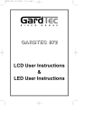
The 1600 system consists of a central unit with full control facilities.Additionally,
provision is made for connecting up to three remote keypads. It may also be supplied
without control facilities at the central panel.
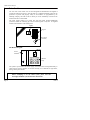
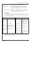
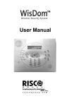
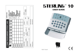
Display
1
Part
2
3
4
5
6
7
8
9
*
0
#
Keypad
Full
Off
Keyswitch
(if fitted)
Full
Part
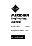
The Remote Keypad:
Display
Power
Indicator
POWER
.
1
2
3
A
4
5
6
B
7
8
9
C
*
0
#
D
Back-lit
keys
The system is powered from the mains supply, and is fitted with a rechargeable battery to
ensure that the system continues to function normally, for a minimum of eight hours,
during a mains power failure.
Before attempting to use the alarm system, please read and
thoroughly familiarise yourself with these instructions.
Page 2
Issue 4
1600 Alarm System Operating Instructions
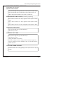
1.1
USING THE SYSTEM - SUMMARY
For full details, refer to Section 2.
SETTING THE SYSTEM
Enter your four digit code (eg 1234) and * to set the system to 'PART' set 'B'
Enter your four digit code (eg 1234) and # to set the system to 'FULL' on
OR use the keyswitch (if fitted) to select 'FULL' or 'PART B' on.
SIMPLE SETTING THE SYSTEM (if enabled in programming)
Enter B and # (6 and # if no 'B' key on keypad) to set the system to 'PART'
set 'B'
Enter C and # (9 and # if no 'C' key on keypad) to set the system to 'PART'
set 'C'
Enter D and # (# twice if no 'D' key on keypad) to set the system to 'FULL'
UNSETTING THE SYSTEM
Enter your four digit code (eg 1234) followed by #
OR Switch key to 'OFF'
SILENCING AN ALARM
Enter your four digit code (eg 1234) followed by #
OR switch key to 'OFF'
Display will indicate cause of alarm
Note and investigate this cause, calling your alarm company if appropriate.
Press # (or turn key to 'FULL' and back to 'OFF' ) to return the system to
normal 'day' mode
USING THE 'CHIME' FACILITY
Switch the 'Chime' on or off by pressing A and # (3 and # if no 'A' key on
keypad)
February 2000
Page 3
Castle Care-Tech Ltd.
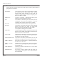
1.2
Terms Used
Certain terms used to describe features and operation of the system may be unfamiliar, the
principal ones are as follows:
DAY MODE
The 'normal' state of the alarm system whilst the premises
are occupied, and the alarm switched 'OFF.' 'Personal
Attack' facilities remain functional, and the system will
continue to monitor itself for evidence of tampering. Also
known as 'UNSET' or 'OPEN'
SWITCH ON
The action of activating, or 'SETTING' the alarm system,
whether by use of the keypad or keyswitch.
SET
The condition of the alarm system when armed, after the
switching on process has been completed - ie after the
completion of the exit time. Also known as 'CLOSED.'
FULL SET
The condition of the alarm when the entire system is set
PART SET
The condition of the alarm system when a pre-programmed
portion of the system is not armed - for example when
setting the system at night whilst still in the premises.
Two separate Part Setting areas are available.
EXIT TIME
The time delay permitted after switching the system on and
before it becomes armed - during which you must leave the
premises, and close the final exit door.
ENTRY TIME
The time delay permitted by the system after entering by the
authorised route, and during which the system must be
switched off, or an alarm will sound.
ENTRY-EXIT ROUTE
The portion of the alarm system linked to the Exit and
Entry timers, through which exit and entry must be made.
ZONE or CIRCUIT
A division of the system which is separately identified in
the indications at the control.
ZONE or CIRCUIT
FAULT
Condition of one of the zones when one (or more) detectors
are not clear, thus preventing the system from being 'set' eg a door left open.
ZONE OMISSION
The facility to disable an individual zone (or zones) whilst
setting the system
SYSTEM FAULT
An incorrect electrical condition which may impair the
correct operation of the system - refer to these instructions
for action required.
Page 4
Issue 4
1600 Alarm System Operating Instructions
TAMPER
A fault existing in the wiring, or securing of the housing of
part of the system, preventing normal operation.
PERSONAL ATTACK
(PA)
An alarm generated deliberately, to summon assistance if
being attacked, operative whether system is switched on or
not. If remote signalling is fitted, the PA alarm may be
silent.
REMOTE SIGNALLING The facility (if fitted) for the system to automatically
communicate by telephone line with a remote Alarm
Receiving Centre to initiate a call to the police.
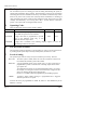
1.3
The Display
The 7-segment LED display indicates the condition of your alarm system. This will clearly
show any information requiring your attention, as indicated in these instructions. The most
important indications are as follows:
'Normal' Indications
d
. (full stop)
System in 'day' mode
System is 'set'
'Fault' Indications
d flashing
Figure
1-7
System is awaiting
reset by engineer
A fault or alarm has
originated on the zone
numbered.
'Chime' is enabled
F-1 (alternating)
System tamper fault
Code accepted, whilst
FULL setting the system
F-2 (alternating)
Mains Failure
- flashing
As above, whilst being
PART set.
F-3 (alternating)
System voltage fault
Green LED
(on keypad[s])
Mains supply healthy
F-4 (alternating)
Battery fault
F-5 (alternating)
Telecom Line Fault
F-7 (alternating)
Alarm generated at
keypad
d.
- (single 'bar')
You will observe other indications whilst using the Manager Functions of the system, as
itemised in Section 6 of this manual.
February 2000
Page 5
Castle Care-Tech Ltd.
1.4
The Keypad
The 10 numeric keys are for entering your code for setting and unsetting the system, or
entering other information when required. Four lettered keys (A,B,C,D) are provided on
remote keypads. Functions available on these keys are available on alternative keys where
these are not present. The # (YES) and * (NO) keys allow confirmation or cancelling of
codes entered, also the choice of 'Full' or 'Part' setting the system. Always enter your code
carefully and deliberately, never leaving more than 3 seconds between consecutive
presses, or the system will cancel digits already entered.
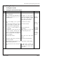
1.5
Operating Codes
There are three levels of access to the system as follows:
Details of use
Code
Factory pre-set To change
USER
4 different codes may be programmed
These enable the system to be set and unset.
1234
See 6.2
MANAGER
A single code must be programmed, to provide
access to the 'Manager' menu only, so that
additional functions may be used.
2222
See 6.3
ENGINEER
A single code is available to the installing company engineer to access the
programming facilities of the system
1.6
The Keyswitch (if fitted)
The keyswitch provides an alternative to the keypad to set, unset or reset the system. If set
by the Keypad, the system may be unset by the Keyswitch, but NOT vice versa..
1.7
Levels of setting
The system may be used in a variety of ways to maximise your security. These are:
FULL SET The entire system is armed, and in the event of an intrusion, an alarm will
be sounded, and (if fitted) a police call initiated.
PART SET
A pre-programmed portion of the system only is set. The system may be
programmed to provide a reduced level of warning outputs in this mode eg no police call.
Two different 'Part' settings are provided (designated 'B' and 'C') to permit,
for example, one setting to be used to set the downstairs at night, and the
other to set upstairs and the garage during the day.
Part Set 'C' is available ONLY if programmed by the installing engineer.
CHIME
Provides a simple 'Chime' warning if a programmed zone is triggered
whilst the premises are occupied.
Note that the areas pre-programmed for PART 'B', PART 'C' and CHIME may all be
different, or overlap.
Page 6
Issue 4
1600 Alarm System Operating Instructions
2
Using the System
2.1
Setting the System
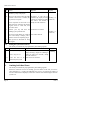
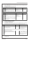
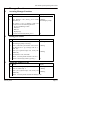
2.1.1
Setting the System with the Keypad
Step Action
Response
Display
a
Verify that all doors, etc. are closed, and
that 'd' is displayed
b
Enter your 4-digit code, followed by # if Acceptance of code will be '-'
the system is to be FULL set, or * if to confirmed by display showing a (flashing if
single 'bar' (flashing if PART PART set)
be PART ('B') set.
set). After a few seconds, a
steady tone will commence.
c
Leave the building by the specified Continuous tone sounds.
route.
To set the system silently (eg at night if Tone will be aborted.
part of the family is asleep): press *
within 2 seconds of completing step b.
d
If a detector is in fault condition, eg a
door is opened
If this detector is part of the exit route,
you may continue, ensuring that all
doors are closed behind you; otherwise
correct the fault before attempting to
leave the building
The tone will become
The display
intermittent
will indicate
When closed, the tone will the number
become steady once more.
of a
detection
zone in fault
condition
e
Close the Final exit door
Tone will cease when timer '.'
expires
f
When door is fully secure, press 'Push to Tone will cease immediately
Set' button (if fitted)
g
The system may be programmed for the external strobe to flash briefly to
confirm that the system is set.
h
If the tone does not cease at the pre-set A fault exists, re-enter the
time
building, switch off the alarm
and correct the fault before
trying again.
February 2000
'd'
'-'
(flashing if
PART set)
Page 7
Castle Care-Tech Ltd.
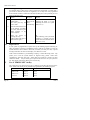
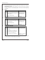
2.1.2
Step
Setting the System using the Keyswitch (if fitted)
Action
Response
Display
a
Verify that all doors, etc. are closed,
and that 'd' prompt is displayed
'd'
b
Insert your key and turn from the 'OFF' Acceptance of code will be '-'
position to the 'FULL' or 'PART' ('B') confirmed by display showing (flashing if
a single 'bar' (flashing if PART PART set)
on position, as required.
set). After a few seconds, a
If the keyswitch has been left in an steady tone will commence.
'ON' position by switching off with the
keypad, switch to 'OFF' first, then
proceed as above.
c
Remove your key and leave the Continuous tone sounds.
building by the specified route.
'-'
(flashing if
PART set)
To set the system silently (eg at night if Tone will be aborted.
part of the family is asleep): press *
within 2 seconds of completing step b.
d
Then proceed as described for using
the keypad.
2.1.3
Setting the system to Part Set 'C'
Step
a
This facility is available only if programmed by the installing engineer.
Action
Response
Press C, followed by #
If no 'C' key, use 9 #
b
Display
Acceptance of code will be confirmed by '-' flashing
display showing a single 'bar' (flashing if
PART set). After a few seconds, a steady
tone will commence.
Leave the area to be Wait for the tone to silence.
protected by the system
'.'
It is possible to adjust the zones on which Part Set 'C' operates, as described at 6.4
2.2
Omitting Individual Zones
This facility is available only if programmed by the installing engineer.
Whilst the continuous exit tone is sounding, press the number of the zone you wish to
omit, followed by '#' - repeating for additional zones (up to 3) if required. The number of
the zone omitted will be displayed, and the last omission will remain displayed until the
system is set.
Page 8
Issue 4
1600 Alarm System Operating Instructions
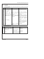
2.3
Unsetting the System
NOTE: deviating from the prescribed ENTRY-EXIT route before switching the system
off will cause an alarm.
2.3.1
Unsetting the system with the Keypad
Step
Action
Response
a
Enter the building by the prescribed Intermittent
route only
commence
b
Enter your 4-digit code, followed by #
2.3.2
Display
tone
will '.'
The tone will cease
'd'
Unsetting the system with the Keyswitch (if fitted)
Step
Action
Response
Display
a
Enter the building by the prescribed Intermittent tone will '.'
route only
commence
b
Insert your Key and turn from On to The tone will cease
OFF.
If the keyswitch is already in the 'OFF'
position, first turn it to 'FULL' then
return to 'OFF'
2.4
Action Following an Alarm
2.4.1
Cancelling a daytime alarm
'd'
An alarm may occur whilst the system is 'unset' by deliberate action (ie operating a
Personal Attack switch) or by the effects of a Fire, or a wiring fault. In this event:
Step Action
Response
Display
a
Enter your 4-digit code, followed by #
The alarm Will show the number of the
OR: Insert your Key and turn from 'OFF' to will silence zone initiating the alarm, or a
'FULL' and back to 'OFF'
code indicating the nature of
a system fault (see 1.3)
b
Note the information shown on the Display, investigate the cause, and advise your alarm
company of any action required.
c
Reset the system by pressing the # key
(OR turn Key from 'OFF' to 'ON' and back
again.)
'd' - if ' d' is flashing, reset by
the alarm company is
required, and the system
cannot be used until this is
done. (see 2.4.3 )
NOTE: a FIRE alarm signal will pulse off and on every two seconds to distinguish it from
an intruder alarm.
February 2000
Page 9
Castle Care-Tech Ltd.
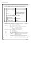
2.4.2
Unsetting following an Alarm
An automatic timer is fitted to the system to silence the external bell or sounder after a
pre-set time to minimise annoyance to neighbours, etc. but may have been programmed
for the internal sounders to remain live after this has taken place. The system may be reset
before or after this action.
Step Action
Response
Display
a
Enter your 4-digit code,
followed by #
OR insert your Key and
turn to 'OFF'
b
Note the information shown
on the Display, investigate
the cause, and advise your
alarm company of any
action required.
c
Reset the system by
pressing the # key
(OR turn Key from 'OFF' to
'ON' and back again.)
2.4.3
The alarm will
silence, if not
done
automatically
Will show the number of the zone
initiating the alarm, or a code
indicating the nature of a system
fault (see 1.3)
'd'
If 'd' is flashing, reset by the alarm
company is required, and the
system cannot be used until this is
done. (see 2.4.3)
Engineer Reset
If your system is programmed to require reset by the installing engineer following an
alarm, the display will show a FLASHING 'd' and it will not be possible to re-use the
system until this is done. Whilst in this mode, each time you enter your code, a special
four digit "anticode" will show on the display, one character at a time.
Under certain circumstances, your Installing Company, or Alarm Receiving Centre may
permit you to reset the system without an Engineer being present. Under these
circumstances, quote this "anti-code" - stating that your system has a 'Castle Care-Tech
1000 Series Panel,' and you will be given a special code to enter to free your system for
use. This special code will be valid for one occasion only.
2.5
Use of 'SIMPLE SET' facility
The system may be set using two keys only, as follows, but the full code must be used to
unset. NOTE: This facility is only available if programmed by the installing engineer.
Function:
Simple set
Alternative if no lettered keys
Page 10
PART set 'B'
Press B #
Use 6 #
PART set 'C'
Press C #
Use 9 #
FULL set
Press D #
Use # #
Issue 4
1600 Alarm System Operating Instructions
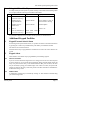
2.6
Using the 'Chime' Facility
You may switch part of the system to provide warning of an intruder in the building whilst
it is occupied, without restricting your freedom of movement.
Step Action
Response
Display
a
Press A, followed by #
(Use 3# if no 'A' key)
Chime now active
'd.'
b
Intruder triggers
programmed zone
System' Chimes'
Shows number of zone in
which intruder is moving
c
Intruder moves to
another zone
System 'Chimes'
Number updates
d
Press #
e
Press A, followed by #
(Use 3# if no 'A' key)
Resets to 'd.'
Home Alone Chime 'd'
now inactive
It is possible to adjust the zones on which 'Chime' operates, as described at 6.4
3
Additional Keypad Facilities
3.1
Keypad Personal Attack Alarm
If switching off the system under duress, it is possible to initiate a Personal Attack alarm
by pressing the '3' and '9' keys simultaneously. This facility is available at all times.
The alarm is reset as described at 2.4
NOTE the alarm may be programmed to be SILENT if a Police Call Unit is fitted to the
system.
3.2
Keypad Alerts
These facilities are available only if programmed by the installing engineer.
3.2.1
Just in Case Timer
If you are nervous about answering the door to a stranger, the 'Just in Case' timer may first
be set by entering '1*' A pre-set time period will begin, during which the alarm control will
'beep' every few seconds. Once you are satisfied that the caller poses no threat, the timer
may be cancelled, by using your normal 4-digit code. If this is not done, the system will
generate an alarm at the expiry of the time period. This alarm will NOT be transmitted to
an Alarm Receiving Centre.
3.2.2
Medical Alert
A medical alert warning may be initiated by entering ' 4*' This should be cancelled using
your normal 4-digit code.
February 2000
Page 11
Castle Care-Tech Ltd.
3.2.3
Fire Alarm
The keypad may be used as a fire alarm call point by entering ''7*'' This will cause an
alarm to sound, pulsing on and off at two-second intervals. This alarm will NOT be
transmitted to an Alarm Receiving Centre.
3.2.4
Switch Lighting
An output may be triggered to switch lighting (or other application, as installed) by
entering '0*'. The output will revert to normal after 30 seconds.
4
Reviewing Time and Date setting
On pressing the * key alone whilst the system is in normal mode (ie display showing 'd'),
the current time and date setting will be displayed, one character at a time, in the form:
HH MM DD MM
ie
HOURS MINUTES DAY MONTH shown sequentially.
eg
14 30 18 07 would indicate 2.30 pm, 18th July. To adjust this setting, refer 6.5
5
System Faults
5.1
System Tamper Fault (F-1)
This indicates a fault in the wiring which requires attention by the alarm company.
5.2
Mains Failure (F-2)
This indicates a break in the mains supply to the alarm control equipment. A battery back
up supply is provided which should enable the system to continue functioning normally
for a minimum of 8 hours. In the event of the failure being prolonged, the alarm company
should be advised.
5.3
System Voltage Fault (F-3)
This indicates that a fault has occurred in the system power supply or battery charging
circuits, and should be reported to the alarm company.
5.4
Battery Fault (F-4)
This indicates a faulty or disconnected stand-by battery in the system, which should be
reported to the installing company.
5.5
Telecom Line Fault (F-5)
If a remote signalling device is fitted to your system, a fault on the Telecom line whilst
the system is unset, will cause the alarm to respond with a continuous 'chirping' tone. You
may cancel this warning by entering your code, followed by # (or by switching the
keyswitch on and off again). The warning will NOT repeat in the event of an intermittent
fault, unless the system has been set and unset in the meantime.
Page 12
Issue 4
1600 Alarm System Operating Instructions
6
Manager Functions
6.1
Accessing Manager Functions
Step
Action
Display
a
Ensure that the system is in normal mode
'd'
b
Enter Manager Code (factory pre-set 2222) 'E' flashing
followed by #
(The Manager prompt)
The system is now in 'Manager mode' and
provides access to the following functions:
Set User and Manager Codes
Walk Test
Bell Test
Display Logs
c
6.2
To return to normal (day) mode, press *
Setting User Codes
Step
6.3
'd'
Action
Display
a
Decide which code is to be changed, and ensure 'E' flashing
that 'Manager prompt' is showing.
b
Enter 1, followed by the number of the code to '.' flashing
be changed, and # - eg to change Code No: 3,
enter 13#
c
Enter your required 4-digit code, slowly and 'E' flashing
deliberately.
d
To DELETE a code, enter 0000
NOTE: it is NOT possible to delete Code No. 1
e
Return to normal (day) mode by pressing *
'd'
Setting the Manager Code
Step
Action
Display
a
Ensure that 'Manager prompt' is showing.
'E' flashing
b
Enter 15, followed by #
'.' flashing
c
Enter your required 4-digit code, slowly and 'E' flashing
deliberately.
NOTE: it is NOT possible to delete the Manager code
February 2000
Page 13
Castle Care-Tech Ltd.
6.4
Zone Selection
The zones on which 'Chime' monitoring is operative and on which Part Set 'C' functions
may be adjusted as follows:
Please note that this facility enables the Manager to ADJUST zones already programmed
for 'Chime' or 'Part Set C' by the installing engineer - NOT to select a zone not previously
programmed.
6.4.1
Chime
Step
6.4.2
Action
Display
a
Ensure that Manager prompt is showing
'E' flashing
b
Enter 4, followed by zone number, and # - '1' flashing if the zone is
eg 41# for zone 1
active, steady if not.
c
Enter 0 to change setting
d
Press *
Part Set 'C'
Step
6.5
'E' flashing
Action
Display
'E' flashing
a
Ensure that Manager prompt is showing
b
Enter 5, followed by zone number, and # '1' flashing if the zone is
- eg 51# for zone 1
active, steady if not.
c
Enter 0 to change setting
d
Press *
'E' flashing
Setting Time and Date
Step
Action
Display
a
Ensure that 'Manager prompt' is showing 'E' flashing
b
Enter 70#
'.'
c
Enter HOURS, as for example 14#
'.'
d
Enter MINUTES, as for example 30#
'.'
e
Enter Date, as for example 18#
'.'
f
Enter MONTH, as for example 07#
'E' flashing - returned to
'Manager prompt.'
In this example, the system has been set to 2.30 pm 18th July. The setting may be
reviewed by pressing '*' whilst the 'd' prompt is displayed.
Page 14
Issue 4
1600 Alarm System Operating Instructions
6.6
Testing the System:
6.6.1
Walk Test
This function enables you to test that all the detectors are working correctly, without
generating an alarm.
Step Action
Response
Display
a
Ensure that 'Manager
prompt' is showing.
'E' flashing
b
Enter 20 and #
'.'
c
Commence
test
by System will 'Chime' Zone number corresponding
triggering
one
of once as detector is with that detector will be
displayed
triggered
detectors on the system.
d
Continue
to
trigger System will 'Chime' Zone number corresponding
additional detectors
once as each detector is with that detector will be
displayed, and will 'scroll'
triggered
(alternate) with all zones
which
have
previously
triggered
e
At end of testing
f
Press *
6.6.2
Step
Numbers of ALL zones
triggered will be scrolling on
display, even though some
(or all) are now clear.
Returns
mode
to
manager 'E' flashing
Bell and Strobe Test
Action
Response
Display
a
Ensure
that
'Manager
prompt' is showing.
b
Enter 60 and #
External alarm bell (or '1' flashing
siren) will sound
c
Press *
Sounder silenced, system 'E' flashing
returns to manager mode
February 2000
'E' flashing
Page 15
Castle Care-Tech Ltd.
6.7
Displaying System Logs
The system logs contain a history of events relevant to the operation and maintenance of
the system, divided in to 'Alarm' events, 'Trouble' events and 'Activations'. These are
stored in chronological order, and are displayed commencing with the most recent.
Step
Action
Display
a
Ensure that 'Manager prompt' is 'E' flashing
showing.
b
Enter 30 and #
Display will show a character
dependant upon the type of the most
recent log entry - see details below.
c
Press # or 0
Advances to next part of log entry
If '0' is used, information displayed will include time and date for this
entry, if '#' is used, this information will be by-passed.
6.7.1
d
Continue to press # (or 0) and '.' indicates end of a log entry
read information logged
e
Pressing # (or 0) moves to next Continue as above.
log entry
f
Press * (whilst '.' showing)
'E' flashing
Activation Records
If the initial character of a log entry is 'A' the entry is an ' Activation' - ie a S etting or
Unsetting event. The information recorded is as follows:
OR
S:
U:
Records system being SET
Records system being UNSET
Figure (0,1,2,3 or 4): Setting (or unsetting) was performed by:
0=
Keyswitch or Simple set
1,2,3 or 4 = Number of PIN code used.
If the record is a Setting event, additional information will follow:
F:
If was FULL set
OR
P:
If was PART 'B' set
OR
9:
If was PART 'C' set
o, followed by a figure, records the number of any circuits omitted
. (full stop)
Identifies the end of record - scroll to next entry
(with #) or exit (with *).
eg:
Page 16
A S 2 F o 4 o 5 . Records the system being Set by code holder 2,
in Full Guard, omitting circuits 4 and 5
AU0
Records the system being Unset by the Keyswitch
Issue 4
1600 Alarm System Operating Instructions
6.7.2
An Alarm or Trouble record
If the initial character of a log entry is ' a' the entry records an alarm event, a ' t' records a
trouble event. The information recorded is as follows:
OR
Figure: Shows the number of the alarm circuit triggering the alarm
Letter 'F' alternating with Figure:
Shows that alarm originated
from a system fault, identified as follows:
F-1
F-2
F-3
F-4
F-5
F-6
F-7
System (SAB or BOX) tamper
Mains Failure
Over or Under Volts
Battery Fault
Telecom Line Fault
System Re-start
Keypad generated alarm
This information will be displayed thus:
a2
t7
t F-4
6.7.3
Records an alarm created on circuit 2
Records a tamper fault on circuit 7, whilst system unset.
Records a battery fault.
Display of Time and Date
If scrolled through a log record with '0' key, the system will additionally indicate the Time
and Date associated with that event, in the format
HH MM DD MM
ie
HOURS MINUTES DAY MONTH shown sequentially, one character at a time.
eg
14 30 18 07 would indicate 2.30 pm, 18th July
Note: Castle Care-Tech Ltd. reserve the right to change the specification of
this system at any time in the interests of product improvement
February 2000
Page 17
Castle Care-Tech Ltd.
THIS PAGE LEFT BLANK FOR NOTES
Page 18
Issue 4
1600 Alarm System Operating Instructions
THIS PAGE LEFT BLANK FOR NOTES
February 2000
Page 19
Castle Care-Tech Ltd.
THIS PAGE LEFT BLANK FOR NOTES
Page 20
Issue 4
INSTRUCT-30
© Castle Care-Tech Ltd.