1
MYD-SAMA5D3X User Manual
MYD-SAMA5D3X
User Manual
Version V1.3
MYD-SAMA5D3X User Manual
Version History
Version Number
V1.0
Description
Initial Version
Time
2013.05
Simplify part details; Modify the section 4.5 and 5.4
V1.1
2013.08
part of the compiler command
V1.2
Correct mistakes; Add 7.0-inch LCD’s support
2013.08
Updating 256MB DDR2 support features;
Updating kernel compiling method;
V1.3
Updating images and sources path;
Correct mistakes;
Remove Chapter 3 MDK Example Code
2013.09
MYD-SAMA5D3X User Manual
Directory
Directory ............................................................................................................................. 1
Chapter 1 Product Overview ............................................................................................ 1
1.1 Product Description ..................................................................................................... 1
1.2 Product Overview ......................................................................................................... 1
1.3 Product Features .......................................................................................................... 2
1.4 Product Packing ........................................................................................................... 5
Chapter 2 Hardware Resource Introduction ................................................................... 6
2.1 CPU module + Base Board Resources Overview .................................................. 6
2.2 CPU module Introduction ............................................................................................ 7
2.2.1 CPU module architecture and CPU features .................................................... 7
2.2.2 DDR2 SDRAM ....................................................................................................... 8
2.2.3 Serial DATAFLASH .............................................................................................. 9
2.2.4 NORFLASH & NANDFLASH ............................................................................ 10
2.2.5 ETHERNET Module ........................................................................................... 11
2.3 Base Board Introduction............................................................................................ 11
2.3.1 Power supply & Push button ............................................................................. 11
2.3.2 CAN....................................................................................................................... 12
2.3.3 RS485 ................................................................................................................... 13
2.3.4 HSMCI Module .................................................................................................... 14
2.3.5 SODIMM Interface .............................................................................................. 14
2.3.6 Smart DAA Module ............................................................................................. 16
2.3.7 Audio Module ....................................................................................................... 17
2.3.8 USB Module ......................................................................................................... 18
2.3.9 ETHERNET Module ........................................................................................... 19
2.3.10 HDMI Module .................................................................................................... 20
2.3.11 USART Module & DBUG ................................................................................. 21
2.4 Jumper Setting ........................................................................................................... 22
MYD-SAMA5D3X User Manual
Chapter 3 Linux System Guide ...................................................................................... 23
3.1 Outline.......................................................................................................................... 23
3.2 Software Resources .................................................................................................. 24
3.3 Start Linux System ..................................................................................................... 25
3.3.1 Install Download Tool ......................................................................................... 25
3.3.2 Connect Board to PC ......................................................................................... 25
3.3.3 Automatic Download .......................................................................................... 26
3.3.4 Manual Download ............................................................................................... 27
3.3.5 4.3-inch and 7.0-inch LCD configuration ......................................................... 35
3.4 Linux Development Environment Structure ........................................................... 37
3.5 Installation and Compile ............................................................................................ 37
3.5.1 Create Working Directory .................................................................................. 37
3.5.2 Install Cross Compiler Tools ............................................................................. 38
3.5.3 Install AT91Bootstrap Source and Compile .................................................... 38
3.5.4 Install uboot Source and Compile .................................................................... 38
3.5.5 Install and Compile Linux kernel Source Code .............................................. 39
3.5.6 Install and Compile Linux File System............................................................. 39
3.6 Make Linux File System ............................................................................................ 40
3.6.1 Write Demo Program hellomyir ........................................................................ 40
3.6.2 Mount UBIFS File System ................................................................................. 40
3.6.3 Modify UBIFS System Files .............................................................................. 42
3.6.4 Regenerate UBIFS System File ....................................................................... 42
3.7 Linux application......................................................................................................... 44
3.7.1 Touch Screen Calibration .................................................................................. 44
3.7.2 U-disk application................................................................................................ 45
3.7.3 SD Card application............................................................................................ 46
3.7.4 Play MP3 Music .................................................................................................. 46
3.7.5 Network Port Test ............................................................................................... 46
3.7.6 Telnet Test ........................................................................................................... 48
3.7.7 Login board via telnet ......................................................................................... 49
MYD-SAMA5D3X User Manual
3.7.8 Mount NFS file system ....................................................................................... 50
3.7.9 RTC application................................................................................................... 51
3.8 Qt Guide ...................................................................................................................... 51
3.8.1 Qt cross compile tool chain ............................................................................... 52
3.8.2 Qt development environment ............................................................................ 55
Chapter 4 Android System Guide .................................................................................. 59
4.1 Overview ...................................................................................................................... 59
4.2 Software Resources .................................................................................................. 60
4.3 Build Android System ................................................................................................ 61
4.3.1 Install Download Tool ......................................................................................... 61
4.3.2 Connect Board and SAM-BA ............................................................................ 61
4.3.3 Automatic Download .......................................................................................... 62
4.3.4 Manual Download ............................................................................................... 62
4.3.5 4.3-inch and 7.0-inch LCD configuration ......................................................... 70
4.4 Compile Android System Files ................................................................................. 71
4.4.1 Android System Principle .................................................................................. 71
4.4.2 Compile System Files ........................................................................................ 72
4.5 Android System Application...................................................................................... 73
4.5.1 USB Keyboard Test ............................................................................................ 73
4.5.2 Browse Picture Test ........................................................................................... 73
4.5.3 Play Audio Test ................................................................................................... 74
4.5.4 Ethernet Test ....................................................................................................... 76
4.5.5 APK Test .............................................................................................................. 78
Appendix 1 FAQ ............................................................................................................... 79
Appendix 2 sales FAQ and technical support .............................................................. 82
MYD-SAMA5D3X User Manual
Chapter 1 Product Overview
1.1 Product Description
MYIR has lunched MYD-SAMA5D3X series boards which are based on Atmel
ATSAMA5D3X series processor (SAMA5D31, SAMA5D33, SAMA5D34, SAMA5D35
based on ARM Cortex-A5). Running at up to 536 MHz, carries 256MB NandFlash, 4MB
Data-Flash(16bits), 256/512MB DDR2 SDRAM. It has rich peripheral interfaces:
High-speed USB2.0, Audio input, audio output, LCD interface, CAN interfaces, JTAG
debug interface, Serial port and Micro SD card interface. The MYD-SAMA5D3 board
support Linux 3.6.9 and Android 4.0.4 and deliver full periphery driver source code help
users to make quick software application and evaluation for ATMEL SAMA9D3 ARM
Cortex-A5 processors.
1.2 Product Overview
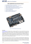
Figure 1-1
1
MYD-SAMA5D3X User Manual
1.3 Product Features
The MYD-SAMA5D3 integrates components and periphery interfaces for developing
ARM Cortex-A5, and its key features as follow:
High-performance architecture -
Based on the ARM Cortex-A5 core
with floating-point unit, the SAMA5D3 series is ideal for applications requiring
high-precision computing and fast data processing. Features a 64-bit internal
bus architecture and 32-bit wide DDR controller running up to 166MHz that offers
up to 1328MB/s of bandwidth.
Market-leading low power consumption - Ideal for battery- operated
applications, the SAMA5D3 series consumes less than 200mW when running at
maximum speed and under 0.5mW in low-power mode.
Comprehensive peripheral set for connectivity and user
interface applications - Includes Gigabit and 10/100/1000 Ethernet, up to
three HS USB ports, dual CAN, three SDIO/SD/MMC, UARTs, SPIs, TWIs, soft
modem, LCD controller with graphics accelerator, camera interface, 12-bit ADC,
32-bit timers and more.
State-of-the-art security -
Includes secure boot, Advanced Encryption
Standard (AES)/Triple Data Encryption Standard (DES) encryption engine,
Secure Hash Algorithm (SHA) and True Random Number Generator (TRNG).
Low system cost - the 0.8mm ball pitch package reduces the PCB design
complexity. A simple power management scheme and impedance matching on
DDR lines reduce the need for external components. Three USB ports save the
cost of an external USB hub.
The basic features of MYD-SAMA5D3X are as follow:
Electrical parameters:
2
MYD-SAMA5D3X User Manual
Working temperature
Industrial level Temperature: -40°C ~ 85°C
commercial level temperature: 0°C ~ 70°C
Operating humidity: 0 to 90%
Electrical Specifications: +5V power supply
Base Board: +5V power supply
CPU module: +3.3V power supply from SODIMM200 DDR2 connector
Mechanical Dimensions:
Base Board: 154mm x 110 mm
CPU module: 45mm x 67.6 mm
Processor:
SAMA5D31//D33/D34/D35 (32 bits ARM v7-A Thumb2 processor) runs at up to
536MHz
32KB Data Cache, 32KB Instruction Cache
Memory:
160KB chip ROM, 128KB chip SRAM
512MB DDR2 SDRAM (256MB DDR2 for option)
256MB Nandflash
16MB NorFlash(16 bits)
4MB DataFlash
Audio and Video Interface:
An 3.5mm Audio Input Interface
An MIC input interface
A Two-channel 3.5mm Audio Output Interface
Transmission Interface:
Standard JTAG Interface
Micro SD Card Interface
SD/MMC Interface
Serial Ports
1x DBGU Port (Debug Unit)
3
MYD-SAMA5D3X User Manual
1xUSART(5 pin)
Two CAN Interfaces (Only MYD-SAM A5D34 and MYD-SAMA5D35 have CAN
Interface)
2 High-speed USB HOST Interfaces
A Mini USB Host/Device Interface
Ethernet MAC
processor
Ethernet
SAMA5D31
SAMA5D33
SAMA5D34
SAMA5D35
10/100 M
10/100/1000 M
10/100/1000 M
Dual Ethernet
LED Indicator:
A Power Indicator (CPU module: Red)
A Users Light/System Heartbeat Light (CPU module: Blue)
A Power Indicator (Base Board: Red)
4
MYD-SAMA5D3X User Manual
1.4 Product Packing
No
Name
Number
Note
MYD-SAMA5D3X Development
1
1
Base Board+CPU module
Board
2
1.5 Meters Crossover Cable
1
3
1.5 Meters Mini USB 2.0 Cable
1
4
5V/2A DC Power adapter
1
5
Serial Cable
1
6
Product DVD
1
DB9-To-DB9 9pins
Include Schematic (PDF), User
Manual, Source Code, etc.
7
4.3/7.0 inch LCD Touch Screen
1
5
optional
MYD-SAMA5D3X User Manual
Chapter 2 Hardware Resource
Introduction
2.1 CPU module + Base Board Resources Overview
MYD-SAMA5D3X board features are shown in table2-1:
Name
5D31
5D33
5D34
5D35
Atmel SAMA5D31/5D33/5D34/5D35(ARM
Processor
Cortex-A5 core, Frequency at up to 536MHz)
512MB DDR2 SDRAM
Memory
(256MB DDR2 for optional)
256MB Nand-Flash, 4MB Data-Flash, 16MB
Flash
NorFlash(16 Bits)
USB HOST
USB
2
2
2
2
1
1
1
1
Audio Input
1
1
1
1
MIC Input
1
1
1
1
Audio Output
1
1
1
1
1
0
0
1
0
1
1
1
DBGU Serial
1
1
1
1
USART1
1
1
1
1
JTAG Interface
1
1
1
1
1
1
1
0
Mini USB
Host / Device
Audio
ETH 10/100M
Ethernet Port
Network
ETH 1000M
Ethernet Port
Serial
JTAG
Support 4.3-inch
LCD
Touch Screen
6
MYD-SAMA5D3X User Manual
Real Time Clock On
RTC
Board and backup
1
1
1
1
1
1
1
1
1
1
1
1
1
1
1
1
battery
20 Pins User
Extended Interface
Extended
30 Pins User
Interface
Extended Interface
60 Pins User
Extended Interface
Power
5V Power Input
1
1
1
1
SD Card
Micro SD Interface
1
1
1
1
SD/MMC
SD/MMC Interface
1
1
1
1
CAN
CAN Interface
0
0
2
2
RS485
RS485 Interface
1
1
1
1
User Button
1
1
1
1
System Button
3
3
3
3
Button
Table 2-1
2.2 CPU module Introduction
About CPU module details please refer to the user manual "MYD- SAMA5D3X CPU
module user manual. PDF".
2.2.1 CPU module architecture and CPU features
(1) CPU module architecture is shown in figure 2-1:
7
MYD-SAMA5D3X User Manual
Figure 2-1
(2) CPU
The Atmel SAMA5D3 series is a high-performance, power-efficient embedded MPU
based on ARM Cortex-A5, achieve 536MHZ with power consumption levels below 0.5mW
in low-power mode. The device features a flexible size instruction and data caches,
Memory Management Unit (MMU) and Floating-Point Unit (FPU). The Cortex-A5
processer implements the ARM-v7 VFPv4-D16 architecture and runs 32-bits ARM
instructions, 16-bits Thumb instructions and 8-bit Java byte codes in Jazelle state. The
processor has the ARM, Thumb ThumbEE, Jazelle states controlled by the T bit and J bit
in the CPSR.
2.2.2 DDR2 SDRAM
DDRAM device key features:
VDD=+1.8V±0.1V, VDDQ= +1.8V ±0.1V
All inputs and outputs are compatible with SSTL_18 interface
8
MYD-SAMA5D3X User Manual
Auto refresh and self-refresh
Organizational structure:8 blanks, Page size: 128 Meg x 16 (16 Meg x 16 x 8
banks)
Programmable CAS latency (CL)
Programmable CAS additive latency (AL)
Programmable burst lengths: 4 or 8
Adjustable data-output drive strength
2.2.3 Serial DATAFLASH
4MB dataflash key features:
Single 2.7V-3.6V Supply
Serial Peripheral interface (SPI) Compatible
Support SPI Modes 0 and 3
70 MHz Maximum Clock Frequency
Flexible, Uniform Erase Architecture
4-Kbyte Blocks,32-Kbyte Blocks,64-Kbyte Blocks, Full Chip Erase
Individual Sector Protection with Global Protect/Unprotect Feature
64-Kbyte Physical Sectors
Hardware Controlled Locking of Protected Sectors
Flexible Programming
Byte/Page Program(1 to 256 Bytes)
Automatic Checking and Reporting of Erase/Program Failures
JEDEC Standard Manufacture and Device ID Read Methodology
Low Power Dissipation
7 mA Active Read Current (Typical)
15 µA Deep Power-Down Current (Typical)
Endurance:100,000 Program/Erase Cycles
Data Retention: 20 Years
Complies with Full industrial Temperature Range
9
MYD-SAMA5D3X User Manual
Industry Standard Green (Pb/Halide-free/RoHS Compliant) Package Options
8-lead SOIC (200 mil wide)
16-lead SOIC (300 mil wide)
2.2.4 NORFLASH & NANDFLASH
(1) 16MB norflash key features:
Organization:
Page size: 128K Bytes(4Blocks top to bottom)
Block size: 32k Bytes
Read Operation:
Random Read: 25 us
Serial Access: 25 ns
Fast Write Cycle Time:
Page Program time: 200 us(Typ)
Block Erase Time: 20 us (Typ)
Power:
VCC (core): 1.7 V - 2.0 V
VCCQ (I/O): 1.7 V - 3.6 V
Endurance: 100,000 Program/Erase Cycles
Data Retention: 10 Years
(2) 256MB nandflash key features:
Organization:
Page size: 2K + 64 Bytes
Block size: 128K + 4K Bytes (64 Pages)
Plane size: 1056Mb((128K+4K)x1024Blocks)
Device size: 2112Mb(1056Mbx2planes)
Array performance
Read page : 25 us
Program page:200 us(TYP:1.8v,3.3V)
10
MYD-SAMA5D3X User Manual
Erase block: 700us(TYP)
Power: 2.7V - 3.6V
Endurance: 100,000 Program/Erase Cycles
Data Retention: 10 Years
48-pin TSOP type1,CPL package
WP# signal: Write protect entire device
2.2.5 ETHERNET Module
ETHERNET key features are as follows:
Single-chip 10/100/1000Mbps IEEE compliant Transceiver
RGMII1.3 Interface support
25MHZ crystal is used to generate all required clocks
Power down and power saving modes
MDO/MDIO Management Interface
48-pin (5mm x 5mm) QFN package
Power supply
VCC (core): 1.2 V
VCCQ (I/O): 3.3 V /2.5 V
2.3 Base Board Introduction
2.3.1 Power supply & Push button
(1) Device power supply is shown in figure 2-2
11
MYD-SAMA5D3X User Manual
Figure 2-2
(2) Push button is shown in figure 2-3
Figure 2-3
2.3.2 CAN
SAMA5D34 and SAMA5D35 have CAN receive/send interface. Its key features are
as follows:
Fully compatible with the “ISO 11898” standard
High speed (up to 1Mbaud)
Very low Electro Magnetic Emission (EME)
Different receiver with wide common-mode range for high Electro Magnetic
Immunity (EMI)
An unpowered node does not disturb the bus lines
Transmit Data (TxD) dominant time-out function
Silent mode in which the transmitter is disabled
Bus Pins protected against transients in an automotive environment
12
MYD-SAMA5D3X User Manual
Input levels compatible with 3.3V and 5V devices
Thermally protected
Short-circuit proof to battery and to ground
At least 110 nodes can be connected
CAN receive/send circuit figure 2-4:
Figure 2-4
2.3.3 RS485
RS485 receive/send key features:
Electrical data isolation
Compliance to ANSI TIA/EIA RS-485-A-1998 and ISO 8482:1987(E)
Transfer speed reach high as 500kbps
low power consumption, current <=2.5mA
compatible 5v and 3v power supply (VDD1)
Bus device numbers <=256
work temperature: -40°C to +85°C
RS485 circuit is shown in figure 2-5.
Figure 2-5
13
MYD-SAMA5D3X User Manual
2.3.4 HSMCI Module
HSMCI Module is shown in figure 2-6:
Figure 2-6
2.3.5 SODIMM Interface
(1) LCD Hardware interface is shown in figure 2-7:
Figure 2-7
(2) JTAG interface is shown in figure 2-8:
14
MYD-SAMA5D3X User Manual
Figure 2-8
(3) User interface is shown in figure 2-9:
Figure 2-9
15
MYD-SAMA5D3X User Manual
(4) ISI interface is shown in figure 2-10:
Figure 2-10
2.3.6 Smart DAA Module
Smart DAA Module is shown in figure 2-11:
Figure 2-11
16
MYD-SAMA5D3X User Manual
2.3.7 Audio Module
Audio Performance
91dB SNR (‘A’ weighted @ 48kHz) ADC
96dB SNR (‘A’ weighted @ 48kHz) DAC
ADC and DAC Sampling Frequency: 8kHz - 96kHz
2 or 3-Wire MPU Serial Control Interface
Programmable Audio Data interface Modes
I2S, Left, Right Justified or DSP
16/20/24/32 bit Word Lengths
Master or Slave Clocking Mode
Stereo sound output and input
The output and input volume control
Highly Efficient Headphone Driver
Playback only 3.0mW
Analog Pass Through Power only 2.4mW
32-PIN QFN package(4 x 4mm, 0.4mm pitch)
Circuit is shown in figure 2-12:
Figure 2-12
17
MYD-SAMA5D3X User Manual
2.3.8 USB Module
(1) USB HOST mode key features are as follows:
110mΩ (5V Input) High-Side MOSFE Switch
500mA Continuous Load Current per Channel
110µA Typical On-State Supply Current
1µA Typical Off-State Supply Current
Current-Limit/Short Circuit Protection
Thermal Shutdown Protection under Overcurrent Condition
Under voltage Lockout Ensures that Switch is off at Start Up
Output can be Forced Higher than Input(Off-State)
Open-Drain Fault Flag
Slow Turn ON and Fast Turn OFF
Enable Active-High or Active-Low
USB HOST Interface circuit is shown in figure 2-13:
Figure 2-13
(2) mini-USB Host / Device key features are as follows:
70-mΩ High-Side MOSFET
500 mA Continuous Current
Thermal and short-Circuit Protection
Accurate Current Limit(0.75A min, 1.25 A max)
18
MYD-SAMA5D3X User Manual
Operating Range:2.7V to 5.5V
0.6-ms Typical Rise Time
Deglitched Fault Report
Bidirectional Switch
Ambient Temperature Range: -40°C to 85°C
ESD Protection
Mini-USB circuit is shown in figure 2-14:
Figure 2-14
2.3.9 ETHERNET Module
ETHERNET key features are as follows:
Single-chip 10/100Mbps IEEE 802.3 compliant Ethernet Transceiver
RGMII1.2 Interface support with 50MHz reference clock output to MAC, and
option to input 50MHz reference clock
Programmable interrupt output
On-chip termination resistors for the differential pairs
Baseline Wander Correction
Power down and power saving modes
32-pin QFN package (5mmx 5mm)
19
MYD-SAMA5D3X User Manual
MDC/MDIO Management Interface for PHY register configuration
Power supply:
VCC (core): 1.2 V
VCCQ (I/O): 3.3 V /2.5 V
ETH Module interface circuit is shown in figure 2-15:
Figure 2-15
2.3.10 HDMI Module
HDMI key features:
Support HDMI1.3,SimplayHD,DVI1.0 protocol
DVD-AUDIO support 4xIIS input
Support 2-channel 192HZ or 8-channel 96HZ
Programmable DDC control system design
Flexible interrupt register
20
MYD-SAMA5D3X User Manual
72-pin QFN package (10x10mm)
Support ICE 60958 or ICE 61937
Support MDO/MDIO management interface
VCC (core): 1.2 V
VCCQ (I/O): 3.3 V /2.5 V
HDMI Module interface circuit is shown in figure 2-16:
Figure 2-16
2.3.11 USART Module & DBUG
USART Module interface is shown in figure 2-17:
21
MYD-SAMA5D3X User Manual
Figure 2-17
2.4 Jumper Setting
Jumper Initial
Description
ON(Jumper close)
OFF(Jumper open)
JP1
OFF
Enable DataFlash(on CPU
module)
Disable DataFlash(CPU module)
JP2
OFF
Boot from external Memory
Boot from ROM
JP3
ON
RXD1 signal connection
RXD1 signal close
JP4
ON
CTS1 signal connection
CTS1 signal close
JP5
ON
Power supply
Power supply by SHDN signal
JP6
ON
VBAT power supply
VBAT power close
JP7
1-2
(1-2)pin, VDDANA power supply
3V3
(2-3)pin,VDDANA power supply 3V
JP8
OFF
J8 SD card write protect
Disable J8 SD write protect
JP9
OFF
UART2 output at J26 as 485
signal
UART2 output at J3 as usart
Table 2-2
22
MYD-SAMA5D3X User Manual
Chapter 3 Linux System Guide
3.1 Outline
This chapter describes how to run Linux system and embedded Linux applications,
the process of drive development in MYD-SAMA5D3X development board. It includes the
development environment to build, compile source code, image download and Linux
application and driver example. The default startup is that NandFlash start the initial
system. Product is Linux system at the factory and the NandFlash content distribution and
some analysis are as bellows:
Figure 3-1
(1) Boot-Strap
After power on system, the first class boot program is copied automatically from
NandFlash to internal SRAM and begins to implement by CPU. The main role is to
23
MYD-SAMA5D3X User Manual
initialize CPU and external RAM and u-boot is copied from NandFlash to external RAM,
and then jump to u-boot entry and start u-boot;
(2) u-boot
Secondary boot program, which is used for kernel image updates, load kernel and
boot kernel starts;
(3) u-boot Env
Configure environment variables and provide u-boot running parameters, such as ip
address, start a command, kernel boot parameters;
(4) sama5d3x.dtb
Describe hardware device tree, U-boot DTB in the start-up will Flash when the
address of the file as the inlet parameters are passed to the kernel;
(5) Linux Kernel
Design Linux 3.6.9 kernel for MYD-SAMA5D3X.
(6) Root FS
The buildroot file system support QT graphical application.
3.2 Software Resources
Category
Boot
program
Name
Remark
Boot Strap
First boot program, source code available
u-boot
Secondary boot program, source code available
Linux kernel only for MYD-SAMA5D3X hardware,
Linux kernel
Linux 3.6.9
source code available
USB Host driver supports the mode of OHCI and
USB Host
EHCI transmission, source code available
USB Device
USB Device Driver (Gadget) , source code available
Ethernet
Ethernet driver, source code available
MMC / SD
MMC/SD Card driver, source code available
Device
Drivers
NandFlash/Smart-Media driver, source code
NandFlash
available
24
MYD-SAMA5D3X User Manual
TWI(I2C)
I2C driver, source code available
SPI
SPI driver, source code available
WM8904
WM8904 Audio driver, source code available
LCD driver, support 4.3 inch, Scalable 7 inch, source
LCD Controller
code available
RTC
RTC clock driver, source code available
4 -wire resistive touch screen driver, source code
Touch-Screen
available
PWM (pulse width modulation ) driver, source code
PWM
available
USART
Serial port driver, source code available
LED driver, including GPIO LED PWM LED driver ,
LED
source code available
The buildroot file system support QT graphical
System Files
QT
application, source code available
Table 3-1
3.3 Start Linux System
3.3.1 Install Download Tool
Here use SAM-BA-v2.12, it can find in CD: “03-Tools\SAM-BA\sam-ba_2.12.exe”,
specific installation method, please follow document “Tools\SAM-BA\sam-ba install.pdf”.
Install pack “sam-ba_2.12_patch4.exe” after “sam-ba_2.12.exe”.
3.3.2 Connect Board to PC
(1) Connect Board to PC (Please follow steps sequentially), Specific steps are as
follows:
① Switch development board to 5 v (power off-position)
25
MYD-SAMA5D3X User Manual
② Connect to PC and board through mini-USB
③ Disconnect JP1, JP2 and hold CS_BOOT button, At the same time switch
development board to USB_5V. If first time the PC opportunities prompt to install board
driver, Select SAM-BA installation directory under the relevant position shown in figure
3-2:
Figure 3-2
(2) If there is figure 3-3 in "computer->properties->Management-> device manager->
port", which shows board driver has been installed (According to the actual situation, here
for COM4).
Figure 3-3
(3) Connect J28 to PC by serial cable, set up Serial Terminal: Baud rate115200, data
bit 8, no parity, stop bit 1, no rts/cts. COM port number is set by actual situation.
3.3.3 Automatic Download
Note: please pull out SD card before download, otherwise an error may happen
Take downloading of image for 4.3-inch LCD and 512MB DDR2 configure as example.
26
MYD-SAMA5D3X User Manual
After complete chapter 3.3.1 and 3.3.2, open CD-ROM directory:
“02-Images\Linux-image\LCD_4.3_DDR2_512MB”, double-click
“sama5d3xek_demo_linux_nandflash”. Then SAM- BA will download Linux image
automatically to board. Entire download process takes about three minutes. When pop”
logfile.log” automatically, reset board, there will be Linux start information.
Linux use, please refer to chapter 3.7.
3.3.4 Manual Download
Note: please pull out SD card before download, otherwise an error may occur
Take downloading of image for 4.3-inch LCD and 512MB DDR2 configure as example.
Using SAM - BA manually download Linux, all image files in this section can be founded in
the product directory of the CD: 02-Image\Linux-image\LCD_4.3_DDR2_512MB.
(1) After complete chapter 3.3.1 and 3.3.2, open SAM-BA to set corresponding
parameters. Connection is “USB-serial\COMXX” (XX is each computer's COM port,
choose it by actual situation, here is COM4) board select at91sama5d3x-ek. And then
click “Connect”, specific settings and connected results are shown in figure 3-4, 3-5:
Figure 3-4
27
MYD-SAMA5D3X User Manual
Figure 3-5
(2) Click NandFlash tab and execute Enable NandFlash Erase All, Enable OS
PMECC parameters in Scripts tab (select an action and click next to "Execute" execution).
When Execute Enable OS PMECC, Pop - up dialog box, click OK to use the default
settings, the specific operation is as follows in figure 3-6:
Figure 3-6
28
MYD-SAMA5D3X User Manual
① Select "Enable NandFlash" in Scripts tab, and then click "Execute" to Enable
NandFlash. Refer to figure 3-7:
Figure 3-7
② Select "Enable OS PMECC parameters" in Scripts tab and then click "Execute",
Settings refer to figure 3-8 (Note :do not select Trimffs):
29
MYD-SAMA5D3X User Manual
Figure 3-8
③ Select "Erase All" in Scripts tab, then click "Execute", Erase NandFlash. Refer to
figure 3-9:
30
MYD-SAMA5D3X User Manual
Figure 3-9
④ Download [ boot. bin] refer to figure 3-10 and 3-11:
Figure 3-10
Figure 3-11
31
MYD-SAMA5D3X User Manual
⑤ Download [u-boot. bin] to 0x40000. Refer to figure 3-12:
Figure 3-12
⑥ Download [ubootEnvtFileNand-Flash. bin] (this file generated by sam-ba when
programing) to 0x000C 0000. Refer to figure 3-13:
32
MYD-SAMA5D3X User Manual
Figure 3-13
⑦ Download [sama5d3xek.dtb ] to 0x0018 0000. Refer to figure 3-14:
Figure 3-14
33
MYD-SAMA5D3X User Manual
⑧ Download Linux kernel [uImage] to 0x0020 0000. Refer to figure 3-15 and figure
3-16:
Figure 3-15
Figure 3-16
34
MYD-SAMA5D3X User Manual
⑨ Download [rootfs. ubi] to address: 0x80000. Refer to figure 3-17(Note: Select
Enable OS PMECC parameters, and click “Execute” to select Trimffst.):
Figure 3-17
(3) Finally, restart board to boot Linux system normally. About the use of Linux in
detail please refer to section 3.7.
3.3.5 4.3-inch and 7.0-inch LCD configuration
“Bootstrap”, “uboot”, “kernel” and “file system” for using 4.3-inch and 7.0-inch LCD
development board are the same, Choose different sizes of LCD just by “uboot” to the
“kernel” boot parameters of different "lcd=x", If this parameter is not specified, the default
configuration using a 4.3 -inch LCD. The following in Linux system, for example.
Product CD directory:”02-Images\Linux-image\” have been launched parameters
configured “sama5d3x_demo_linux_nand flash.tcl” at related directory, respectively is:
LCD_4.3:
console=ttyS0,115200 mtdparts=atmel_nand:8M(bootstrap/uboot/kernel)ro,-(rootfs)
rootfstype=ubifs ubi.mtd=1 root=ubi0:rootfs lcd=480x272
35
rw
MYD-SAMA5D3X User Manual
LCD_7.0:
console=ttyS0,115200 mtdparts=atmel_nand:8M(bootstrap/uboot/kernel)ro,-(rootfs)
rootfstype=ubifs ubi.mtd=1 root=ubi0:rootfs lcd=800x480
rw
Kernel boot parameters can also be used in the uboot starts to dynamically change,
change the steps as follows:
(1) Connection and configured a serial port control terminal, restart the development
board. When the control terminal output "Hit any key to stop auto boot: 1" fast press the
space bar to enter uboot console mode:
U-Boot 2012.10 (Jul 22 2013 - 10:26:52)
CPU: SAMA5D31
Crystal frequency:
12 MHz
CPU clock
:
528 MHz
Master clock
:
132 MHz
DRAM: 512 MiB
WARNING: Caches not enabled
NAND: 256 MiB
MMC: mci: 0
In:
serial
Out: serial
Err: serial
Net: macb0
Warning: failed to set MAC address
Hit any key to stop autoboot: 1
(2) Input the command "print" to print all the environment variables sets of the current
uboot, the value of the variable "bootargs" is the kernel boot parameters:
U-Boot> print
baudrate=115200
bootargs=console=ttyS0,115200
mtdparts=atmel_nand:8M(bootstrap/uboot/kernel)ro,-(rootfs)
rw
rootfstype=ubifs
ubi.mtd=1 root=ubi0:rootfs lcd=480x272
bootcmd=nand read 0x21000000 0x00180000 0x10000; nand read 0x22000000
0x00200000 0x380000; bootm 0x22000000 - 0x21000000
bootdelay=1
ethact=macb0
stderr=serial
stdin=serial
stdout=serial
36
MYD-SAMA5D3X User Manual
Environment size: 356/131067 bytes
(3) 4.3-inch LCD please refer to (2), if 7.0-inch LCD, need to amend "LCD = 480
x272" in “bootargs” for "LCD = 800 x480", the command is as follow:
U-Boot> set bootargs " console=ttyS0, 115200
mtdparts=atmel_nand:8M(bootstrap/uboot/kernel)ro,-(rootfs) rw rootfstype=ubifs
ubi.mtd=1 root=ubi0:rootfs lcd=800x480"
(4) Enter the following command to save the new configuration of the kernel boot
parameters:
U-Boot> saveenv
Saving Environment to NAND...
Erasing redundant NAND...
Erasing at 0x100000 -- 100% complete.
Writing to redundant NAND... done
(5) Restart the development board or direct input "boot" command guidance system
will use the new configuration of the kernel boot parameters:
U-Boot> boot
Note: Calibrate configuration will not be available after change configuration, need to
be run "ts_calibrate" terminal to recalibrate again. If Android system, can directly click on
"AndroidCalibration" to run calibrate tool.
3.4 Linux Development Environment Structure
The contents of this chapter please refer to "description VirtualBox's Linux-based
development environment to build pdf".
3.5 Installation and Compile
3.5.1 Create Working Directory
Establish a working directory and copied 04-Linux_Source to “/opt/linux“ (own
working directory also can be edited).
# mkdir /opt/linux
# cd /opt/linux
# cp -r /media/cdrom/04-Linux_Source/* ./
37
MYD-SAMA5D3X User Manual
3.5.2 Install Cross Compiler Tools
Decompress cross compiler tool chain.
# sudo apt-get install build-essential git libncurses5-dev u-boot-tools
# sudo apt-get install flex bison texinfo zip unzip zlib1g-dev gettext
# sudo apt-get install gperf libsdl-dev libesd0-dev libwxgtk2.6-dev
# sudo apt-get install uboot-mkimage
# sudo apt-get install flex bison texinfo unzip gettext
# sudo apt-get install g++ xz-utils
# cp /media/cdrom/03-Tools/Cross_compiler/gcc-linaro-arm-linux-gnueabihf
-4.7-2013.04-20130415_linux.tar.bz2 ./
# sudo tar xjf gcc-linaro-arm-linux-gnueabihf-4.7-2013.04-20130415_linux.tar.bz2 -C
/opt/
# export ARCH=arm
#export
CROSS_COMPILE=/opt/gcc-linaro-arm-linux-gnueabihf-4.7-2013.04-20130415_linux/bin
/arm-linux-gnueabihf-
3.5.3 Install AT91Bootstrap Source and Compile
(1) Install
# cd /opt/linux/Bootstrap
# tar xvjf at91bootstrap.tar.bz2
# cd at91bootstrap
(2) Compile
# make mrproper
# make at91sama5d3xeknf_uboot_defconfig
# make
At91SAMA5D3Xek-Nand-Flashboot-3.1.bin in binary directory is AT91Bootstrap file.
Rename it to “boot.bin” for automatic download. AT91Bootstrap is a boot loader for
ATMEL chip, which initialize necessary hardware (GPIO Clock, SDRAM, etc.), then copy
uboot to SDRAM to run.
3.5.4 Install uboot Source and Compile
(1) Install
# cd /opt/linux/U-boot
# tar xvjf u-boot-at91.tar.bz2
38
MYD-SAMA5D3X User Manual
# cd u-boot-at91
(2) Compile
# make distclean
# make sama5d3xeknf_512MB_config
# make
If use the board carries 256MB DDR2, please replace
“sama5d3xeknf_512MB_config” with “sama5d3xeknf_256MB_config”.
U-boot.bin is U-boot file that we download in u-boot-at91 directory.
3.5.5 Install and Compile Linux kernel Source Code
(1) Install
# cd /opt/linux/Linux-at91
# tar xvjf linux-at91.tar.bz2
# cd linux-at91
(2) Compile
# ./make_image.sh linux-512mb
If use the board carries 256MB DDR2, please replace “linux-512mb” with
“linux-256mb”.
After compile kernel, uImage file in arch /arm/boot/ directory is Linux image files that
we need. sama5d31ek.dtb, sama5d33ek.dtb, sama5d34ek.dtb, sama5d35ek.dtb is Linux
device tree image file what we need.
3.5.6 Install and Compile Linux File System
(1) Install
# cd /opt/linux/Buildroot-at91
# tar xvjf buildroot-at91.tar.bz2
# cd buildroot-at91
(2) Compile
# sudo apt-get install flex bison texinfo unzip gettext
# sudo apt-get install g++ xz-utils
# cp buildroot.config .config
# make
It takes long time to compile kernel, rootfs.ubi in arch/arm/boot/ directory is Linux file
system.
39
MYD-SAMA5D3X User Manual
3.6 Make Linux File System
“rootfs.ubi” can be formulated and modified. Here is an example how to add
application into file system root directory.
3.6.1 Write Demo Program hellomyir
First of all, Program “hellomyir”
(1) Create and compile” hellomyir.c”
# vi hellomyir.c
Enter the following in “ hellomyir.c”, save and exit:
# include <stdio.h>
int main(int argc, char *argv[])
{
int i;
printf("========== Hello Myir ==========\n");
printf("argc: %d\n", argc);
for(i = 0; i < argc; i++)
{
printf("argv[%d]: %s\n", i, argv[i]);
}
return 0;
}
(2) Compile “hello myir.c”
Add cross-compiler tools path to PATH:
# export PATH=$PATH: /opt/gcc-linaro-arm-linux-gnueabihf-4.7-2013.04-20130415\
_linux/bin/arm-linux-gnueabihfUse the cross compiler tool to compile:
# arm-none-linux-gnueabi-gcc -static -o hellomyir hellomyir.c
3.6.2 Mount UBIFS File System
UBIFS is a new flash file system by nokia engineers under the help of Szeged
University, which is considered the next generation of JFFS2 files system. UBIFS file
system specifically for the large-capacity FLASH embedded mobile devices, mounting
UBIFS file system must have mtd interface, while Ordinary PC usually has no mtd
40
MYD-SAMA5D3X User Manual
manage disk. So here needs nandsim simulator, simulate mtd device with a RAM space,
then mount UBIFS file system. The concrete steps are as follows:
(1) Load UBIFS
Enter the following command:
# sudo apt-get install mtd-utils
# sudo modprobe nandsim first_id _byte=0x2c second_id_byte=0xda
third_id_byte=0x90 fourth_id_byte=0x95
It needs to pass a few parameters to load nandsim: first_id_byte, second_id_byte,
third_id_byte and fourth_id_byte are ID for NANDFLASH of the simulated target.
MYD-SAMA5D3X use NANDFLASH of Samsung K9F2G08U0B. Four ID bytes can be
found in datasheet: 0x2c, 0xda, 0x90, 0x95
If execute successfully, there will be mtd0 and mtd0r0 devices in /dev/directory:
# ls /dev/mtd*
/dev/mtd0 /dev/mtd0ro
(2) Erase mtd0 partition, the operation is as follows:
# sudo flash_eraseall /dev/mtd0
Erasing 128 Kibyte @ ffe0000 -- 100 % complete
(3) Load rootfs.ubi to new mtd0 partition. Here used dd command to load, as follows:
# sudo dd if= rootfs.ubi of=/dev/mtd0
94976+0 records in
94976+0 records out
48627712 bytes (49 MB) copied, 0.73911s, 65.8MB/s
(4) Mount UBIFS system file
After completing the above step, load “ubi” modules and attach to “mtd0”, mount
UBIFS file system like mounting ordinary “mtd” device.
Load ubi modules and attach to mtd0 equipment:
# sudo modprobe ubi mtd=0,2048
Create a new mount point:
# mkdir fsmount
Mount it by the following command:
# sudo mount -t ubifs ubi0_0 fsmount/
# ls fsmount/
bin boot dev etc home lib media mnt proc sbin sys tmp usr var
Now that mount UBIFS file system is successful.
41
MYD-SAMA5D3X User Manual
3.6.3 Modify UBIFS System Files
After mount UBIFS file system successfully, it can modify file contents, such as add,
delete and modify files. It should add compiled demo program “hellomyir” to system root
directory. The operation is as follows:
# sudo cp hellomyir fsmount/
# sync
# ls fsmount
bin boot dev etc hellomyir home lib media mnt proc sbin sys tmp usr var
3.6.4 Regenerate UBIFS System File
After modification, it needs to regenerate file system by mkfs.ubifs tool, Enter the
following command to generate a new UBIFS file system:
# sudo mkfs.ubifs -r fsmount/ -m 2048 -e 126976 -c 2024 \
-o ubifs.img
“mkfs.ubifs” parameter description:
-r
Establish the system file directory
-m Minimum I/O transfer unit size
-e
Logical size of erase block
-c
The largest number of erase logic blocks
-o
Specify the output file
View smallest I/O transfer unit size and logical erase block size by the following
command:
# ubinfo /dev/ubi0
ubi0
Volumes count:
1
Logical eraseblock size:
126976 bytes, 124.0 KiB
Total amount of logical eraseblocks:
2048 (260046848 bytes, 248.0 MiB)
Amount of available logical eraseblocks: 0 (0 bytes)
Maximum count of volumes
128
Count of bad physical eraseblocks:
0
Count of reserved physical eraseblocks: 20
Current maximum erase counter value:
1
Minimum input/output unit size:
2048 bytes
Character device major/minor:
250:0
42
MYD-SAMA5D3X User Manual
Present volumes:
0
View erase block number by using the following command:
# ubinfo /dev/ubi0_0
Volume ID: 0 (on ubi0)
Type:
dynamic
Alignment: 1
Size:
2024 LEBs (256999424 bytes, 245.1 MiB)
State:
OK
Name:
rootfs
Character device major/minor: 250:1
Then use ubinize tool to generate fsimage.ubi file. Firstly, it needs to create
configuration files of ubinize.cfg:
# vi ubinize.cfg
Enter the following, save and exit:
[ubifs]
mode=ubi
image=ubifs.img
vol_id=0
vol_size=64MiB
vol_type=dynamic
vol_name=rootfs
vol_flags=autoresize
vol_alignment=1
Enter the following command to generate final fsimage.ubi file:
# sudo ubinize -m 2048 -p 128KiB -o fsimage.ubi ubinize.cfg
Parameter description of ubinize:
-m The size of minimum input/output byte flash unit
-p
The erase block size of FLASH physical
-o
output file
Here is different mkfs.ubifs parameter, - p parameter represents the physical erase
block size. UBI work in MTD layer, so it needs the MTD parameters, namely physical
parameters. UBIFS work in UBI, so it needs the UBI parameters, namely the logic
parameter. Now, UBI image has been saved in the ubi.img, which not only contains UBIFS
information, but also contains UBI information.
After the completion, generated “fsimage.ubi” file can use the method described in
chapter 4.3.4 to download to 0x800000.
43
MYD-SAMA5D3X User Manual
Reset board and input “root” to login, there is added “hellomyir” file in the root
directory:
buildroot login: root
# cd /
# ls
bin
etc
lib
boot
hellomyir media
dev
home
mnt
proc
sbin
sys
tmp
usr
var
Run helloworld, as follows:
# ./hellomyir
========== Hello Myir ==========
argc: 1
argv[0]: ./hellomyir
3.7 Linux application
After a Linux system running, can be operated by touch screen, can also through the
terminal serial ports, here is how to through the terminal Linux operating, such as U disk,
SD card mount, ETH test and how to play music and so on.
3.7.1 Touch Screen Calibration
Entering system will run the screen calibration procedure automatically. Recalibrate
the touch screen by the following steps if it requires:
(1) Open HyperTerminal (baud rate: 115200 Data bits: 8, Parity: None Stop bits: 1,
data flow control: none). After start Linux, log in as root command:
buildroot login: root
(2) Run the calibration procedure and click the five corresponding calibration points
on the LCD screen. The calibration can be carried out:
# ts_calibrate
xres = 480, yres = 272
Took 12 samples...
Top left : X = 767 Y = 178
Took 14 samples...
Top right : X = 793 Y = 947
Took 13 samples...
Bot right : X = 309 Y = 934
44
MYD-SAMA5D3X User Manual
Took 12 samples...
Bot left : X = 308 Y = 169
Took 10 samples...
Center : X = 557 Y = 556
-29.638855 -0.011581 0.495638
331.720245 -0.364475 0.006420
Calibration constants: -1942412 -758 32482 21739618 -23886 420 65536
(3) After calibration is complete, it needs to restart system calibration to take effect.
The operation is as follows:
# sync
# reboot
3.7.2 U-disk application
(1) Follow information will display on terminal when inserting a u-disk on USB host
port:
usb 1-3: new high-speed USB device number 2 using atmel-ehci
usb 1-3: New USB device found, idVendor=13fe, idProduct=3600
usb 1-3: New USB device strings: Mfr=1, Product=2, SerialNumber=3
usb 1-3: Product: DT 101 G2
usb 1-3: Manufacturer: KINGSTON
usb 1-3: SerialNumber: C1690905
scsi0 : usb-storage 1-3:1.0
scsi 0:0:0:0: Direct-Access
KINGSTON DT 101 G2
8.07 PQ: 0 ANSI: 4
sd 0:0:0:0: [sda] 16076800 512-byte logical blocks: (8.23 GB/7.66 GiB)
sd 0:0:0:0: [sda] Write Protect is off
sd 0:0:0:0: [sda] Write cache: disabled, read cache: enabled, doesn't support DPO or
FUA
sda: sda1
sd 0:0:0:0: [sda] Attached SCSI removable disk
(2) Entering the following command to mount inserted U-disk and view U disk
contents.
# mount -t vfat /dev/sda1 /mnt/
# ls /mnt/usb/
??
??
??-??-???-??-??
?????
BOOTEX.LOG
DSC04807.JPG
FOUND.000
MYD-S5PV210
MYD-SAMA5D3X-Dev-Res
Michael Jackson - Beat It.mp3
Dangerous.mp3
Qt_Arm.rar
qt????
45
MYD-SAMA5D3X User Manual
(3) Unplug U-disk directly when the use is completed, system will uninstall
automatically.
3.7.3 SD Card application
(1) When Micro SD card is inserted, HyperTerminal displays SD card information:
mmc0: host does not support reading read-only switch. assuming write-enable.
mmc1: new high SD card at address aaaa
mmcblk0: mmc1:aaaa SU02G 1.84 GiB
mmcblk0: p1
(2) Mount and view SD card:
# mount -t vfat /dev/mmcblk0p1 /media/sdcard
# ls /media/sdcard/
360
LOST.DIR
duba
360Download
Music
iReader
Android
PicStore
mm_sec.dat
Audio
QQ
qqservicec.log
Backup
QQBrowser
scan.txt
BaiduMapSdk
Qzone
tencent
BlackBerry
RMS
tmp
DCIM
Sounds
wandoujia
Download
audio_play_list.txt
GT-S3600C.samsung
bluetooth
(3) Pull out SD card directly, system will uninstall it automatically.
3.7.4 Play MP3 Music
Before playing music, connect headphones or stereo to J11 U disk storages music
and is inserted into USB interface.
Play music in U disk by mplayer command in terminal:
# mount -t vfat /dev/sda1 /mnt/
# ls /mnt
# madplay /mnt/Dangerous.mp3
Sounds will come from the headset. Terminal information is shown as follow:
MPEG Audio Decoder 0.15.2 (beta) - Copyright (C) 2000-2004 Robert Leslie et al.
Press “Ctrl+ C” to end playing music.
3.7.5 Network Port Test
46
MYD-SAMA5D3X User Manual
(1) The development board connected to a PC using crossover Ethernet cable,
through the super terminal, for a development board configuration is not the IP address of
the current local area network (LAN) other equipment takes up. Here use address:
192.168.0.2:
# ifconfig eth0 192.168.0.2 up
IPv6: ADDRCONF(NETDEV_UP): eth0: link is not ready
# macb f0028000.ethernet: eth0: link up (1000/Full)
IPv6: ADDRCONF(NETDEV_CHANGE): eth0: link becomes ready
(2) Test board to PC network by ping command (here host IP: 192.168.0.3).
Ping development board in PC:
# ping 192.168.0.10
Refer to figure-3.18:
Figure-3.18
Ping host in board:
# ping 192.168.0.3
PING 192.168.0.3 (192.168.0.3): 56 data bytes
64 bytes from 192.168.0.3: seq=0 ttl=128 time=0.801 ms
64 bytes from 192.168.0.3: seq=1 ttl=128 time=0.377 ms
64 bytes from 192.168.0.3: seq=2 ttl=128 time=0.357 ms
64 bytes from 192.168.0.3: seq=3 ttl=128 time=0.359 ms
64 bytes from 192.168.0.3: seq=4 ttl=128 time=0.447 ms
47
MYD-SAMA5D3X User Manual
3.7.6 Telnet Test
(1) Configure IP (IP can allocate, designated IP 192.168.1.2 in case)
# ifconfig eth0 192.168.1.2 up
(2) Configure Gateway
Test connection with the gateway, as follows:
# ping 192.168.1.1
PING 192.168.1.1 (192.168.1.1): 56 data bytes
64 bytes from 192.168.1.1: seq=0 ttl=64 time=16.455 ms
64 bytes from 192.168.1.1: seq=1 ttl=64 time=2.391 ms
64 bytes from 192.168.1.1: seq=2 ttl=64 time=3.924 ms
64 bytes from 192.168.1.1: seq=3 ttl=64 time=2.254 ms
64 bytes from 192.168.1.1: seq=4 ttl=64 time=2.005 ms
(3) Set 192.168.0.1 as the default gateway:
# route add default gw 192.168.0.1
Test connection with 202.112.17.137:
# ping 202.112.17.137
PING 202.112.17.137 (202.112.17.137): 56 data bytes
64 bytes from 202.112.17.137: seq=0 ttl=54 time=32.202 ms
64 bytes from 202.112.17.137: seq=1 ttl=54 time=24.457 ms
64 bytes from 202.112.17.137: seq=2 ttl=54 time=22.918 ms
64 bytes from 202.112.17.137: seq=3 ttl=54 time=23.178 ms
64 bytes from 202.112.17.137: seq=4 ttl=54 time=29.341 ms
(4) Configure DNS server
View current DNS server address by ipconfig/all command, machine DNS is
202.103.24.68. Set target board's DNS (depend on the circumstances):
# echo "nameserver 202.103.24.68" | tee /etc/resolv.conf
Ping www.baidu.com to test extranet access:
(5) Use Telnet access to the BBS
# telnet bbs.scut.edu.cn
The test result is show in figure 3-19:
48
MYD-SAMA5D3X User Manual
Figure 3-19
3.7.7 Login board via telnet
(1) Configure IP(IP can allocate, designated IP 192.168.1. 166 instead)
# ifconfig eth0 192.168.1.166
(2) Start telenet service
# telnetd
(3) Login board by telenet client
Use telenet in windows(telenet is available when adding system copments in Win7)
as example, type command as follows):
telnet 192.168.1.166
Enter user name:telenet_user,password:telenet, as show in fogure 3-20:
49
MYD-SAMA5D3X User Manual
Figure 3-20
After login on board by telnet, telenet_user can make operations and switch to super
user by follow command:
$ su The current directory will change to /root after this command.
Noted: user cann’t login by root authority directly, the DVD provide telnent_user in
Linux system for login by telenet.
3.7.8 Mount NFS file system
Noted: here we build NFS server on Ubuntu as example.
(1) Build NFS server on Ubuntu
① Install “nfs-kernel-server”
# sudo apt-get install nfs-kernel-server
② Add follow content at file end of /etc/exports (The NFS directory is
/home/jbo/nfsdir,this directory will be mount on clients)
/home/jbo/nfsdir *(rw,sync,no_root_squash)
③ Restart portmap and nfs-kernel-server
# service portmap restart
# service nfs-kernel-server restart
50
MYD-SAMA5D3X User Manual
(2) Mount NFS file system on board
① Configure IP
# ifconfig eth0 192.168.1.166
② Make directory
# mkdir nfs
③ Mount NFS file system, the NFS server IP is 192.168.1.223
# mount -t nfs -o nolock 192.168.1.223:/home/jbo/nfsdir nfs
User can operate nfs’s directory, and the change/modification will be refected on
NFS server /home/jbo/nfsdir.
3.7.9 RTC application
(1) Install button battery to board.
(2) System will set initial value at first start time, so it needs to set the time after
system startup.
Set system time:
# date -s 2013.06.07-15:51:00 ;
hwclock -w Jul 8 10:36:00 BST 2013
Query system time and hardware RTC time:
# date
Fri Jun 7 15:52:22 UTC 2013
# hwclock -r
Fri Jun 7 15:53:22 2013 0.000000 seconds
3.8 Qt Guide
This section describe the methods and steps to using Qt GUI application
development on the MYD - SAMA5D3X, including two parts, the first tells use Qt cross
compile tool chain which is provided in CD. The second part tells how to generated Qt
cross tool chain and related library file from Qt-Embedded source code.
Note: on the development board to download 02-Im ages/Linux directory of Images,
for example, download specific steps refer to 3.3.3 automatic download, or 3.3.4 manual
download. Here for Ubuntu10.04 PC environment.
51
MYD-SAMA5D3X User Manual
3.8.1 Qt cross compile tool chain
For general use Qt program development can be directly supplied CD-ROM Qt cross
tool chain , the disc 02-Images/Linux/Qt_Arm directory contains the tool chain
corresponding Qt library , so with this compiler tool chain the Qt program can be run
directly on the board . CD-ROM provides detailed configuration Qt cross tool chain as
follows:
Configuration items
Value
Build
libs
Debug
no
Qt 3 compatibility
yes
QtDBus module
no
Qt ScriptTools module
yes
Qt XmlPatterns module
no
Phonon module
no
SVG module
yes
WebKit module
yes
STL support
yes
PCH support
yes
MMX/3DNOW/SSE/SSE2
no/no/no/no
iWMMXt support
no
IPv6 support
yes
IPv6 ifname support
yes
getaddrinfo support
yes
getifaddrs support
yes
Accessibility
yes
NIS support
yes
CUPS support
no
52
MYD-SAMA5D3X User Manual
Configuration items
Value
Iconv support
no
Glib support
no
GStreamer support
no
Large File support
yes
GIF support
plugin
TIFF support
plugin (qt)
JPEG support
plugin (qt)
PNG support
yes (qt)
MNG support
plugin (qt)
zlib support
yes
Session management
no
Embedded support
arm
Freetype2 support
yes
Graphics (qt)
linuxfb multiscreen linuxfb
Graphics (plugin)
Decorations (qt)
styled windows default
Decorations (plugin)
Keyboard driver (qt)
tty usb
Keyboard driver (plugin)
Mouse driver (qt)
pc linuxtp pc linuxtp tslib
Mouse driver (plugin)
OpenGL support
no
SQLite support
qt (qt)
OpenSSL support
no
Table 3-2
(1) Install Qt cross compile tools to “/usr/local/”
Set up “qt-arm”, copy Qt cross compile tools to this directory and decompress:
53
MYD-SAMA5D3X User Manual
$ cd ~
$ mkdir qt-arm
$ cd qt-arm
$ cp /media/cdrom/04-Linux_Source/Qt_Arm/Qt-4.5.3_Tslib-1.4.tar.gz ./
$ sudo tar xvzf Qt-4.5.3_Tslib-1.4.tar.gz -C /usr/local/
There will be more than two directories: “qt4.5.3-arm” and “tslib” in “/usr/local”,
“qt4.5.3-arm” contains tools, libraries and header files used in cross-compilation, etc.;
“Tslib” contains link libraries and configuration files used in touch screen.
(2) Set the system environment variables
① If you haven't added “arm-Linux-gnueabi-” to PATH, here cross compiler path is
“/usr/local/gcc-linaro-arm-linux-gnueabihf-4.7-2013.04-20130415_linux/bin”,execute the
following command:
$ export \
PATH=$PATH:/opt/gcc-linaro-arm-linux-gnueabihf-4.7-2013.04-20130415_linux/bin
② Set the environment variable Qt application development
Execute the following command at terminal:
$ export PATH=$PATH:/usr/local/qt4.5.3-arm/bin
$ export LD_LIBRARY_PATH=$LD_LIBRARY_PATH:/usr/local/qt4.5.3-arm/lib
Or add the above command to “/etc/profile”, so set these environment variables
automatically when system login.
(3) Burning Qt library image
Refer to 3.3.3 automatic download or 3.3.4 manual download to burn library image ,
the Images has been set for Qt environment, and already contains the libraries Qt
application Commonly used, supported by the function modules as shown in table 3-2. If
the features provided can't meet actual demand, Please refer to the next section 3.8.2
cross-compilation Qt development environment to configure the required function
modules from the source code.
(4) Compile Qt and run application
There are several Qt sample program in “04-Linux_Source/Qt_Arm/ Qt_Examples/”,
here is “Masterdetail” example how to use Qt cross-compilation tool chain to compile Qt
application and run on the target board.
① Copy program to Qt-arm
$ cd ~/qt-arm
54
MYD-SAMA5D3X User Manual
$ cp /media/cdrom/04-Linux_Source/Qt_Arm/Qt_Examples/masterdetail.tar.gz ./
$ tar xvzf masterdetail.tar.gz
$ cd masterdetail
② Compile the Qt project :
$ qmake -project
$ qmake
$ make
If compilation error “error: QtSql (QtXml) No such file” happens, need to manually add
file: “QT + = SQL (XML)”to “masterdetail. Pro”, after edited “qmake project”.
③ After perform above command, copy “masterdetail” to development board to run
on:
# ls
masterdetail
# chmod 0777 masterdetail
# ./masterdetail -qws
The result is shown in the figure 3-21:
Figure 3-21
3.8.2 Qt development environment
This section describes how compiled Qt cross tool chain and the associated arm-qt
library. This method can be developed Qt operating environment, when Qt library cannot
55
MYD-SAMA5D3X User Manual
meet the actual development needs. Tslib code source and Qt's code source are in the
CD-ROM directory “04-Linux_Source/Qt_Arm/Qt_Arm/Qt_Source”
(1) Establish working directory
$ cd ~
$ mkdir qt-arm
$ cd qt-arm
(2) Compile tslib installation
① Decompress:
$ cp /media/cdrom/04-Linux_Source/tslib.tar.gz ./
$ tar xvzf tslib.tar.gz
$ cd tslib
② Compile installation:
If haven't added “arm-none-Linux-gnueabi-“to the PATH, added it to the
PATH:“/usr/local/GCC-linaro-arm-inux_linux-gnueabihf-4.7-2013.04-20130415/bin”,
perform the following command:
$ export \
PATH=$PATH:/opt/ gcc-linaro-arm-linux-gnueabihf-4.7-2013.04-20130415_linux/bin
Install “automake”, “libtool”:
$ sudo apt-get install automake libtool
Configure “tslib”, installation path can be set up their own, where installed into” /usr/
local/tslib”:
$ ./autogen.sh
$ ./configure CC=arm -linux-gnueabi-gcc CXX=arm-linux-gnueabi-g++
--prefix=/usr/local/tslib --host=arm-linux ac_cv_func_malloc_0_nonnull=yes
Compile installation:
$ make
$ sudo make install
After installing tslib Modify second line "# module_raw input" to "module_raw input",
and must top grid.
(3) Compile install “qt-embedded”:
① Decompress:
$
cp
/media/cdrom/04-Linux_Source/Qt_Arm/Qt_Source
/qt-embedded-linux-opensource-rc-4.5.3.tar.gz ./
$ tar xvzf qt-embedded-linux-opensource-src-4.5.3.tar.gz
$ cd qt-embedded-linux-opensource-src-4.5.3
② Specify cross-compiler:
56
MYD-SAMA5D3X User Manual
Edit “mkspecs/QWS/Linux-arm-g++/qmake. Conf”:
$ vi
mkspecs/qws/linux-arm-g++/qmake.conf
Enter following command, “arm-Linux-“ to be replaced by
“Arm-none-Linux-gnueabi-“ and add”-LTS”, changes are as follows:
# modifications to g++.conf
QMAKE_CC = arm-linux-gnueabi-gcc -lts
QMAKE_CXX = arm-linux-gnueabi-g++ -lts
QMAKE_LINK = arm-linux-gnueabi-g++ -lts
QMAKE_LINK_SHLIB = arm-linux-gnueabi-g++ -lts
③ Qt configuration:
$ ./configure -prefix /usr/local/qt4.5.3-arm -xplatform qws/linux-arm-g++ -release
-opensource -qt-zlib -qt-libtiff -qt-libpng -qt-libmng -qt-libjpeg -make libs -nomake docs
-embedded arm -little-endian -qt-freetype
-depths
8,16,24
-qt-gfx-linuxfb
-qt-kbd-usb
-qt-mouse-pc -qt-mouse-linuxtp
-qt-mouse-tslib
-qt-sql-sqlite
-qt3support -I/usr/local/tslib/include -L/usr/local/tslib/lib -confirm-license
Enter “/configure -help” to look at parameters description.
④ Compile the installation:
$ make
$ sudo make install
⑤ Set environment variables:
Execute following command at terminal:
$ export PATH=$PATH:/usr/local/qt4.5.3-arm/bin
$ export LD_LIBRARY_PATH=$LD_LIBRARY_PATH:/usr/local/qt4.5.3-arm/lib
Or add the above command to “/etc/profile”, so set these environment variables
automatically when system login.
(4) Transplant Qt to development board
① Copy library to the board
Compress Qt files:
$ cd
$ tar
/usr/local/qt4.5.3-arm
-zcf lib.tar.gz
lib
Copy “lib.tar.gz” to development board, and then decompress:
# mkdir -p /usr/local/qt4.5.3-arm
# tar xzvf lib.tar.gz -C /usr/local/qt4.5.3-arm
② Set up environment variable
Environment variable has been written in “/etc/setqtenv“, execute following command
on the development board:
57
MYD-SAMA5D3X User Manual
# source
/etc/setqtenv
Or manually input Settings:
# export LD_LIBRARY_PATH=/lib:$LD_LIBRARY_PATH
# export QTDIR=/usr/local/qt4.5.3-arm
# export T_ROOT=/usr/local/tslib
# export PATH=$T_ROOT/bin:$PATH
# export LD_LIBRARY_PATH=$T_ROOT/lib:$QTDIR/lib:$LD_LIBRARY_PATH
# export TSLIB_CONSOLEDEVICE=none
# export TSLIB_FBDEVICE=/dev/fb0
# export TSLIB_TSDEVICE=/dev/input/event0
# export TSLIB_PLUGINDIR=$T_ROOT/lib/ts
# export TSLIB_CONFFILE=$T_ROOT/etc/ts.conf
# export TSLIB_CALIBFILE=/etc/pointercal
# export QWS_KEYBOARD=USB:/dev/input/event1
# export QWS_MOUSE_PROTO=Tslib:/dev/event0
# export QT_QWS_FONTDIR=$QTDIR/lib/fonts
58
MYD-SAMA5D3X User Manual
Chapter 4 Android System Guide
4.1 Overview
Android is a Linux system based open source operating system, mainly used in
portable devices. Android operating system originally developed by Andy Rubin
development, initially mainly support mobile phone. In 2005 Android is acquainted by
Google, formatting the open mobile phone alliance to improvement it, gradually extended
to the tablet computer and other area. Since its first release Welcomed by the majority of
consumers, Android’s market shares around the world more than Symbian system for the
first time in the first quarter of 2011, ranking first in the world. The data shows that in
February 2012, Android accounted for 52.5% of the share of the global smartphone
operating system market.
Android system is running based on Linux system, mainly made by Linux Kernel,
system libraries, Dalvik virtual machine, application framework, and applications written
mainly by JAVA. Its framework is as shown in figure 4-1:
59
MYD-SAMA5D3X User Manual
Figure 4-1
This chapter describes how to build and run Android 4.0.4 system in MYD-SAMA5D3
X platform, include the following main content:
(1) Build Android system
(2) Compile Android
(3) Android System use
4.2 Software Resources
Software resources are shown in table 4-1:
Category
Name
Note
AT91Bootstrap
Use to load ”Uboot”
1.Support Nand-Flash Erase, read and write
Boot
program
2. Support network to download image
Uboot
3. Support settings, save the environment variable
4. Support display, contrast, modify memory content
5. Support the ”bootm”, “bootargs” settings
Develop
Linux Kernel
Linux
kernel
for
MYD-SAMA5D3X
Linux 3.6.9
hardware
Network
port
ETH0
driver
Serial port driver
USART1,DBGU
USB
USB_HOST*2,USB_OTG
SD card driver
Micro-SD, SDCard
LCD+ touch
LCD driver
GPIO driver
Have been tested to provide the source
Device
Drivers
Android System
Have been tested to provide binary image file
System Files
Files
Table 4-1
60
MYD-SAMA5D3X User Manual
4.3 Build Android System
This chapter describes how to use image to build Android system.
4.3.1 Install Download Tool
Install Atmel ISP download software SAM-BA (2.12 or later, Note: If install SAM-BA
2.11 and earlier versions, it needs to first uninstall the all (SAM-BA and USB driver). If
need two or more SAM-BA version coexistence, different SAM-BA versions use different
USB interface.
4.3.2 Connect Board and SAM-BA
(1) Connect Board to PC (Please follow steps sequentially), Specific steps are as
follows:
① Switch development board to 5 v (power off-position )
② Connect to PC and board through mini-USB
③ Disconnect JP1, JP2 and hold CS_BOOT button, At the same time switch
development board to USB_5V. If first time the PC opportunities prompt to install board
driver, Select SAM-BA installation directory under the relevant position can be installed as
shown in figure 4-2:
Figure 4-2
(2) If the serial interface as shown in Figure 4-3 "my
61
MYD-SAMA5D3X User Manual
computer->properties->Management-> device manager-> port", which shows board driver
has been installed (According to the actual situation, here is COM4).
Figure 4-3
4.3.3 Automatic Download
Note: please pull out SD card before download, otherwise an error may happen
Take downloading of image for 4.3-inch LCD and 512MB DDR2 configure as
example.
After complete chapter 4.3.1 and 4.3.2, open CD-ROM directory:
“02-Images\Linux-image\LCD_4.3_DDR2_512MB”,double-click“sama5d3xek_demo_linu
x_nandflash”. Then SAM- BA will download Linux image automatically to board. Entire
download process takes about three minutes. When pop logfile.log file automatically, reset
board, there will be Android start information.
4.3.4 Manual Download
Take downloading of image for 4.3-inch LCD and 512MB DDR2 configure as example.
All image files used in this chapter can be founded in the CD-ROM directory:
62
MYD-SAMA5D3X User Manual
02-Images\Android-image\LCD_4.3_DDR2_512MB. The NandFlash content of Android
system is divided, as shown in figure 4-4:
Figure 4-4
Download Linux by SAM-BA manually.
(1) After completed chapter 4.3.1 and 4.3.2, double-click samba v2.11, there will
appears interface. Refer to figure 4-5:
Figure 4-5
(2) Click “Connect” to enter SAM-BA. Refer to figure 4-6:
63
MYD-SAMA5D3X User Manual
Figure 4-6
(3) Select NandFlash tab, enable NandFlash in Scripts tab and then click “Execute”.
Refer to figure 4-7:
64
MYD-SAMA5D3X User Manual
Figure 4-7
(4) Select Enable OS PMECC parameters in Scripts tab, then click Execute, using the
default option, click “OK” directly (Note: there cannot check Trimffs). Refer to figure 4-8:
Fi
Figure 4-8
(5) Select Erase All in Scripts tab and then click Execute. Refer to figure 4-9:
65
MYD-SAMA5D3X User Manual
Figure 4-9
(6) Download [boot.bin]. Refer to figure 4-10, 4-11:
Figure 4-10
66
MYD-SAMA5D3X User Manual
Figure 4-11
(7) Download [u-boot.bin] to 0x40000. Refer to figure 4-12:
Figure 4-12
67
MYD-SAMA5D3X User Manual
(8) Download [ubootEnvtFileNand-Flash.bin] to 0x000C 0000. Refer to figure 4-13:
Figure 4-13
(9) Download [sama5d3xek.dtb] to 0x0018 0000 Department. Refer to figure 4-14:
Figure 4-14
68
MYD-SAMA5D3X User Manual
(10) Download Linux kernel [ uImage] to 0x0020 0000. Refer to figure 4-15:
Figure 4-15
(11) Download [rootfs.ubi] to 0x0050 0000. Refer to figure 4-16(Note: be sure to
check Trimffs):
69
MYD-SAMA5D3X User Manual
Figure 4-16
At this point, Android system image file download is completed, and press K1(Reset)
key can restart Android system.
4.3.5 4.3-inch and 7.0-inch LCD configuration
Please refer to 3.3.5 4.3-inch and 7.0-inch LCD configuration. Please note that the
Android kernel boot parameters are different with the Linux boot parameters, the Android
kernel boot parameters are:
LCD_4.3:
console=ttyS0,115200 no_console_suspend
mtdparts=atmel_nand:8M(bootstrap/uboot/kernel)ro,-(rootfs) rw rootfstype=ubifs
ubi.mtd=1 root=ubi0:rootfs init=/init lcd=480x272
LCD_7.0:
console=ttyS0,115200 no_console_suspend
mtdparts=atmel_nand:8M(bootstrap/uboot/kernel)ro,-(rootfs) rw rootfstype=ubifs
ubi.mtd=1 root=ubi0:rootfs init=/init lcd=800x480
70
MYD-SAMA5D3X User Manual
4.4 Compile Android System Files
This chapter will describe the compiled methods and steps of Android system files.
4.4.1 Android System Principle
(1) File description:
File
Description
Boot program Compiled by AT91
boot.bin
Bootstrap source used to start u-boot
u-boot.bin
The secondary boot for boot kernel
Configure the environment variables,
u-boot Env
provided u-boot operation parameters
Describe hardware device tree, u-boot
DTB in the start-up will Flash when
sama5d3x.dtb
the address of the file as the entrance
to the parameters passed to the
kernel
Linux kernel file compiled by Linux
uImage
kernel source code
rootfs.ubi
Android file system
SAM - BA script files, control the
flash_all.tcl
burning process
Automatic programming tools ( MS DOS
batch
file,
the
manual
flash_all.bat
programming
process
require this file )
Table 4-2
(2) The principle of the system
Power on, starts system form Nand-Flash, the start steps is as following:
71
does
not
MYD-SAMA5D3X User Manual
① Fixed boot code in atsama5d3x internal rom and copy a boot program
“at91SAMA5D3Xek-Nand-Flashboot-3.1.bin” in Nand-Flash to SRAM to run. Boot
program initializes hardware basically, such as setting CPU frequency, configure running
PIO, and then copy the secondary boot program “uboot.bin” to DDRAM and begin to
Execute.
② Secondary bootloader uboot is mainly responsible for boot Linux, including set
Linux operating environment, Load Linux image file uImage, pass startup parameters to
Linux, last boot Linux to start.
③ When boot Linux kernel, Android file system will be mounted automatically. At this
point, Android system is booted.
4.4.2 Compile System Files
Android system is running on Linux-based system, so if build Android system, set up
a Linux- based platform firstly.
(1) Decompression cross compiler tool to”/usr/local.compile[ AT91Bootstrap]”
To [at91SAMA5D3Xek-Nand-Flashboot-3.1.bin] ,compile u-boot to [u-boot.bin ] refer to
[3.5.1], [3.5.2], [3.5.3], [3.5.4].
(2) Compile Linux kernell used in Android system
Unzip Linux kernel to working directory:
# cp /media/cdrom/05-Android_Source/Linux-at91/linux-at91.tar.bz2 /opt/android
# cd /opt/android
# tar xvjf linux-at91.tar.bz2
# cd linux-at91
Compile Linux kernel:
# ./make_image.sh android-512mb
For products with 256MB DDR2, please replace “android-512mb” with
“android-256mb”.
Note: make uImage command requires compile environment installed uboot-mkimage
tool; otherwise, use the following command to install tool:
# apt-get install uboot-mkimage
After compile kernel, uImage in directory arch/arm/boot/ is Linux kernel programming
72
MYD-SAMA5D3X User Manual
file. sama5d31ek.dtb, sama5d33ek.dtb, sama5d34ek.dtb, sama5d35ek.dtb is Android
device tree image file what we need.
4.5 Android System Application
4.5.1 USB Keyboard Test
Insert USB keyboard to J24, press the NumLock key, when the lights in the
upper-right corner turn green, it shows USB keyboard can be used as far as on PC to
input.
4.5.2 Browse Picture Test
(1) Select "Gallery" icon. Refer to figure 4-15:
Figure 4-15
(2) Click “Gallery” and select a picture folder, Refer to figure 4-16:
73
MYD-SAMA5D3X User Manual
Figure 4-16
(3) View picture, the result is shown in figure 4-17:
Figure 4-17
4.5.3 Play Audio Test
(1) Enter interface and Select "Music" icon, Refer to figure 4-18:
74
MYD-SAMA5D3X User Manual
Figure 4-18
(2) Select "Songs" option. Refer to figure 4-19:
Figure 4-19
(3) Select a song to play. As shown in figure 4-20:
75
MYD-SAMA5D3X User Manual
Figure 4-20
4.5.4 Ethernet Test
Note: Connect board to router by cable
(1) Enter interface and select icon "Ethernet", refer to figure 4-21:
Figure 4-21
(2) Configure Ethernet, Select "Dhcp" to obtain dynamic IP. Otherwise, select "Static
IP" to set IP address, subnet mask, DNS server, default gateway.. manually. Refer to
figure 4-22:
76
MYD-SAMA5D3X User Manual
Figure 4-22
(3) After configure, input string: www.baidu.com. Refer to figure 4-23 figure 4-24:
Figure 4-23
77
MYD-SAMA5D3X User Manual
Figure 4-24
4.5.5 APK Test
The contents of this chapter please refer to "Android development environment
and use Eclipse.pdf".
78
MYD-SAMA5D3X User Manual
Appendix 1 FAQ
Q1: Report "Connection \USBserial\COMxx not found" (XX: port number, and
according to the situation such as host machine is COM13, then XX is 13), pop up logfile
file contents. As shown below:
-I- Waiting ...
-I- TCL platform : Windows NT
-I- SAM-BA 2.12 on : windows
-I- Retrieved arguments from command line :
-I- argv 0 : \usb\ARM0
-I- argv 1 : at91sama5d3x-ek
-I- argv 2 : sama5d3xek_demo_linux_nandflash.tcl
-E- Connection \USBserial\COM13 not found
-E- Connection list : COM1
Analysis and Answers:
This problem happens due to SAM-BA connection failed, please follow steps:
① Development board switch to 5 v (power off-position )
② Through the micro-USB line connected to the PC and development board
③ Connect the CPU module jumper JP1, JP2 backboard disconnect, hold
CS_BOOT button At the same time development board switches to USB_5v ress NRST
reset board , then turn SW2 on, and then start download.
Display logfile file as follows:
-I- Waiting ...
-I- TCL platform : Windows NT
-I- SAM-BA 2.12 on : windows
-I- Retrieved arguments from command line :
-I- argv 0 : \usb\ARM0
-I- argv 1 : at91sama5d3x-ek
79
MYD-SAMA5D3X User Manual
-I- argv 2 : sama5d3xek_demo_linux_nandflash.tcl
-E- Connection \USBserial\COM3 not found
-E- Connection list : {\USBserial\COM13} COM1
It indicates that port isn’t right, as above -I - argv 0: \ USBserial \ COM3 " , but
connections list is "-E-Connection list: {\ USBserial \ COM13} COM1 " which shows native
port is COM13 not COM3 and it needs to modify COM port ( Note: COM port is that your
host use).
Q2: Download system successfully, but can not start system.
Analysis and Answers:
If download Linux image to board with SD card mounted, system might fail to start
and show following message on Hyper Terminal. Please unplug SD card and try to
download Linux image again.
Q4: Automatic download for a long time, HyperTerminal did not continue to
output download information.
Analysis and Answers:
This may be stuck in automatic download process. It can end sam-ba.exe process in
task manager and then restart download.
If start SAM-BA v2.11, Click Connect and pops up the following window when in
automatic download:
80
MYD-SAMA5D3X User Manual
This failure might be caused by duplicated running SAM-BA, please end duplicated
SAM-BA process and try again.
81
MYD-SAMA5D3X User Manual
Appendix 2 sales FAQ and technical
support
How to buy
We accept paypal payment and bank wire transfer
1.
Paypal payment
Please select the products add into shopping cart, the checkout web page will redirect to
paypal.com for you payment. Shipment fee will calculated automatically by your location region.
2.
Bank wire transfer
Please email or fax us with products list you want, we will send you a pro-invoice with order value
total, shipping cost and bank information.
Shipping details
Please select the shipping area catalogue for you location. If you have carrier account to pay the
shipment fee, please select “Freight collect” and email us the carrier account.
Please visit http://www.myirtech.com/support.asp for more details
Noted
1. The shipment will start in 3 biz days by Fedex Express, it usually take 7 days to reach regular
cities or regions.
2. We will use DHL Express for West asia or middle east countries, it usually take 7 days to reach
regular cities or regions.
3. The remote regions defined by Fedex/DHL may cause delay, 14 days in generally.
4. Some countries have strict import policy, we will help to make shipping invoice with you
requirement, like invoice value, trade term, custom statements and H.S code etc. Please contact
us with these shipment requirements if your country has strict custom affairs.
Support and maintains
MYIR provides 12 months warranty for hardware products if the defects or failures were not
caused by wrong use.
Return steps for defective products
1. Please email or call us get a Return Merchandise Authorization (RMA) by providing purchase
details and reasons for return (defective, incorrect etc).
2. MYIR will make a shipping invoice (list value total, item description etc) for you return request.
China have strict limit on return products, so please use MYIR’s shipping invoice to return items
to avoid custom delay.
Contact:
Tel:+86-0755-22929657 Fax: +86-0755-2553 2724
Mail to: [email protected]
[email protected]
Website: www.myirtech.com
82