1
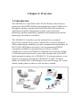
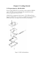
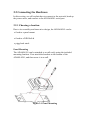
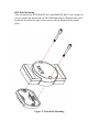
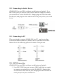
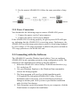
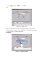
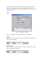
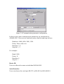
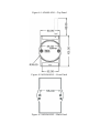
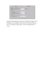
ADAM-4581
User’s
Manual
Table of Contents
CHAPTER 1: OVERVIEW .....................................................................3
1.1 INTRODUCTION ..................................................................................3
1.2 FEATURES ..........................................................................................4
1.3 SPECIFICATION ...................................................................................4
1.4 PACKAGE CHECKLIST .........................................................................5
CHAPTER 2: GETTING STARTED .....................................................6
2.1 PREPARATION FOR ADAM-4581........................................................6
2.2 CONNECTING THE HARDWARE ...........................................................7
2.2.1 Choosing a location ...................................................................7
2.2.2 Connecting to Serial Device ....................................................10
2.2.3 Connecting to PC.....................................................................10
2.2.4 GSM Connection......................................................................10
2.2.5 Power Connection ...................................................................11
2.3 CONNECTING WITH THE SOFTWARE ..................................................11
CHAPTER 3: SOFTWARE UTILITY .................................................12
3.1 CONFIGURING THE ADAM-4581 .....................................................12
3.2 CONFIGURATION UTILITY—TOOL BAR ............................................13
3.3 CONFIGURATION UTILITY—STATUS INFO. .......................................16
3.4 CONFIGURATION UTILITY—MAIN BODY .........................................17
3.4.1 Alarm Configuration................................................................17
3.4.2 Modem .....................................................................................18
3.4.3 Remote Config..........................................................................19
3.4.4 Communication Parameters ....................................................20
CHAPTER 4 UNDERSTANDING ADAM-4581 .................................22
4.1 TOP/FRONT/REAR VIEW...................................................................22
4.2 STICKERS .........................................................................................24
CHAPTER 5 TROUBLESHOOTING .................................................25
Chapter 1: Overview
1.1 Introduction
The ADAM-4581 1-port GSM to RS-232/485 Wireless Data Gateway
product provides GSM CSD data communication as well as SMS service
through the interface with the dual-band GSM (900/1800) module for
applications in facility management systems, water/wastewater
monitoring, pipeline monitoring, unmanned telecommunication facility
monitoring, surveillance, and others.
The ADAM-4581’s interface uses the industrial device standard
RS-232/485 with auto-flow control. ADAM-4581’s built-in intelligent
SMS communication capability provides communication transparency for
RS-232/485 ASCII data conversion. Users are guaranteed GSM AT
commands and SMS for communication are always available.
ADAM-4581 converts ASCII data or commands into a message in SMS
or GSM data mode and can also convert this message back to an ASCII
data/command at another site’s ADAM-4581. If an urgent alarm or event
happens in a field site, through the ADAM-4581’s eight TTL digital
inputs, the ADAM-4581 could instantly send a short message to a control
station, mobile phone or wherever else the alert is needed.
1.2 Features
˙GSM based wireless communication platform
˙GUI based configuration tool provided
˙Remote download for system configuration
˙Standard RS-232/485 interface support
˙Digital input interface support
˙Auto-dial out support for alarm/events
˙SMS (Short Message System) communication support
˙Support in-coming call filtering to protect unauthorized access
˙Watchdog timer support
1.3 Specification
GSM Module:
Antenna connector:
GSM transmission
speed:
Serial port:
RS-232/485 connector:
Serial transmission
speed:
Digital Input:
900/1800 Band
SMA type, 2dBi omni antenna included
1200 bps to 9600 bps
1 port RS-232/485 (RS-485 with auto-flow
control)
Male DB-9
1200 bps to 115.2Kbps
8 channels
Dry contact:
Logic level 0: Close to GND
Logic level 1: Open
Wet contact:
Operation Mode:
Built-in Watchdog
Timer:
LED for diagnostics:
PC-based remote
configuration utility:
Mounting:
Power Supply:
Physical Dimensions:
Power Consumption:
Operating Temperature:
Relative Humidity:
Logic level 0: +2V (max.)
Logic level 1: +4V ~ +30V
SMS, CSD (Analog, Digital (ISDN))
Yes
6 x LED for power supply, GSM status, GSM
communication (TX/RX) and RS-232/485
communication (TX/RX)
Windows 98/NT/2000/XP
DIN-rail, Wall mount
+10 ~ +30 Vdc
60×112×25 mm L*M*H
1.0 W (at unregulated +10 ~ +30Vdc)
0°C ~70°C
0%~95%
1.4 Package Checklist
˙ADAM-4581
˙INET CD-ROM for driver utility and user’s manual
˙One loopback DB-9 tester
˙One crossed null modem connector
˙Five stickers
˙Nylon DIN-rail mounting adapter
˙SECC panel mounting bracket
Chapter 2: Getting Started
2.1 Preparation for ADAM-4581
Prior to using ADAM-4581, be sure that you have applied a GSM900
and/or 1800 SIM card and enabled the data communication mode
(Wireless Application Protocol, WAP).
ADAM-4581 is composed of three boards—CPU, GSM and Carrier.
Open the ADAM-4581 case and insert your SIM card into ADAM-4581
GSM board. Refer to the figure below for SIM card installation.
Figure 2-1 SIM Card Installation
2.2 Connecting the Hardware
In this section, we will explain how to connect to the network, hook up
the power cable, and connect to the ADAM-4581 serial port.
2.2.1 Choosing a location
Due to its versatility and innovative design, the ADAM-4581 can be:
˙fixed to a panel mount
˙fixed to a DIN Rail &
˙piggyback stack
Panel Mounting
The ADAM-4581 can be attached to a wall easily using the included
mounting brackets. First attach the brackets to the bottom of the
ADAM-4581, and then screw it to a wall.
Figure 2-1 Panel Mounting
DIN Rail Mounting
You can mount the ADAM-4581 on a standard DIN Rail. First, using two
screws, attach the metal plate to the DIN Rail bracket. Because the screw
heads are beveled, the tops of the screws will be flush with the metal
plate.
Figure 2-2 Din Rail Mounting
Piggyback Stack
ADAM-4581 can be stacked as seen in the figure below.
Figure 2-3 Piggyback Stack
2.2.2 Connecting to Serial Device
ADAM-4581 has one DB-9 serial port on the bottom of module. For a
RS-232/485 port you can use a DB-9 cable which we supply to connect
your serial device to the ADAM-4581. Simply plug one end of the cable
into the jack, and plug the other end into the serial port jack on your serial
device.
2.2.3 Connecting to PC
When you intend to connect ADAM-4581 to a PC, you have to plug
crossed null modem connector (female) that we provided to the cable.
Please refer to the following picture for details on the pin-outs.
2.2.4 GSM Connection
ADAM-4581 has one DB-9 serial port on the bottom of module.
1. For a RS-232/485 port you can use a DB-9 cable that we supply
to connect your serial device to the ADAM-4581. Simply plug
one end of the cable into the jack, and plug the other end into the
serial port jack on your serial device.
2. For the remote ADAM-4581, follow the same procedure of step
1.
2.2.5 Power Connection
You should take the following steps to connect ADAM-4581 power.
1. Connect the power cord to 2-pin connector.
2. Connect the power cord to power adapter.
If the ADAM-4581 is working properly, the green power LED will light
up, indicating that the ADAM-4581 is receiving power. Furthermore, the
ADAM-4581 provides surge protection to protect it from being damaged
by over-voltage, a 34V surge protection is added to the power end and an
18V surge protection is for the RS-485 end.
2.3 Connecting with the Software
The ADAM-4581 provides Window-based utilities. You can configure
ADAM-4581 in any operating system by using configuration utility. The
following is the installation for setting up the ADAM-4581.
1. Insert the ADAM-4581 driver/utility CD-ROM into the drive (e.g.
D:\) on the host PC.
2. Use your Windows Explorer or the Windows Run command to
execute the Setup program.
3. The Setup program will specify a default installation path,
C:\Program Files\Advantech ADAM-4581 Utility. If a new
destination path is necessary, just click the Browse button to
change to another path. After you have specified the installation
path, click the Next button.
4. After Setup has copied all program files to your computer, click the
Finish button to complete the installation.
Chapter 3: Software Utility
3.1 Configuring the ADAM-4581
The ADAM-4581 provides easy Windows configuration through serial
RS-232 connection. This Windows utility can dynamically show the
status of ADAM-4581 initialization, settings and the mode in which it is
running, and you can configure various parameters for communication
such as serial interface, baud rate, parity and so on. For secure
administration, it allows to restrict the access rights for configuration by
setting the “accept number.” With this secure function enabled, other
GSM devices (ex. GSM cellular phone) will not have permission for
configuration. The Windows utility consists of four functional categories:
Alarm, Modem, Remote Configuration and Communication Parameters.
Note: When you have finished the configuration of these settings for each
category, please follow the steps described below to make these settings
effective on ADAM-4581.
Æ
Æ
3.2 Configuration Utility—Tool bar
File
Figure 3-1 Tool bar—File
Users can keep and restore the configuration settings in “File” menu.
Users can “New,” “Open,” “Save,” and “Save As” configuration settings,
as well as “Exit” the configuration utility.
COM Port
Figure 3-2 Comm. Port setting
By clicking on “Comm Port” on the tool bar, users will see a pop-out
window for assigning Comm port for an ADAM-4581. There are 16
Comm ports selectable for users in the scrollable menu. Click on “OK” to
make it effective.
Mode
Figure 3-3 ADAM-4581 Mode
Users can manually select the desired mode for ADAM-4581.
Off-line
When users choose “Off-line,” the status of ADAM-4581 shown below
will change, accordingly.
On-line Listen
When users choose “On-line Listen,” the status of ADAM-4581 shown
below will change, accordingly.
By choosing “On-line Listen,” users can view in real time the GSM status.
For example
On-line Program
When users choose “On-line Program,” the status of ADAM-4581 shown
below will change, accordingly.
By choosing “On-line Program,” ADAM-4581 is ready to “Download”
the current settings into its firmware. An information window pops out,
asking users to “Turn on and off the power” of ADAM-4581. Then,
theDownload” button becomes visible for downloading. Users MUST
turn off and turn on the power and do NOT click on the “Download”
button immediately until the GSM status
shows:
When the status shows
, it means that users have
successfully updated the firmware with current settings.
Help
Clicking on “Help” on the tool bar, users can see the basic operation steps
and brief introduction to functions of ADAM-4581 configuration utility.
3.3 Configuration Utility—Status Info.
Figure 3-4 Status Information
The lower part of ADAM-4581 configuration utility shows the current
status of connected ADAM-4581. Users can change the settings and
mode, as well as view the corresponding change in real time.
COM Port
Users can view the current COM port assigned to the connected
ADAM-4581.
Mode
There are three modes—Off-line, On-line Listen and On-line
Program—available for ADAM-4581. When “On-line Listen” is selected
in the Mode menu of the tool bar, users can view real time messages
generated from the connected ADAM-4581.
Status
The interaction between users and ADAM-4581 is shown in the Status
text field. For example, “Save Ok!!” “Download Complete!!” “Download
Failed!!” to name a few.
GSM
The status of GSM initialization, communication, operator service signal
strength and so on can be viewed by users in real time.
3.4 Configuration Utility—Main Body
3.4.1 Alarm Configuration
Figure 3-1 Alarm configuration window
In this section, you will learn how to set messages for different alarms.
When the ADAM-4581 configuration utility starts, you can see four
tabs—Alarm, Modem, Remote Config and Communication
Parameters—on the GUI utility as shown above. The checkboxes on left
side of Alarm tab corresponds to the 8 DI channels of ADAM-4581.
These checkboxes allow users to set alarms and corresponding alarm
messages to designated GSM devices through Simple Message Service
(SMS):
Channel
DI0 Lo to Hi
DI0 Hi to Lo
DI1 Lo to Hi
DI1 Hi to Lo
DI2 Lo to Hi
DI2 Hi to Lo
DI3 Lo to Hi
DI3 Hi to Lo
Mapping
Channel1 close to open
Channel1 open to close
Channel2 close to open
Channel2 open to close
Channel3 close to open
Channel3 open to close
Channel4 close to open
Channel4 open to close
DI4 Lo to Hi
DI4 Hi to Lo
DI5 Lo to Hi
DI5 Hi to Lo
DI6 Lo to Hi
DI6 Hi to Lo
DI7 Lo to Hi
DI7 Hi to Lo
Channel5 close to open
Channel5 open to close
Channel6 close to open
Channel6 open to close
Channel7 close to open
Channel7 open to close
Channel8 close to open
Channel8 open to close
For each alarm, two GSM devices can be set to receive the alarm message
by specifying the device phone number in the columns of SMS1 and
SMS2. In the Message text field, put the message that you intend
ADAM-4581 to send when the corresponding alarm occurs.
3.4.2 Modem
Figure 3-2 Modem window
In this section, you can learn to set the basic parameters for how
ADAM-4581 communicates. The two radio boxes, “Analog” and “ISDN”,
on the top of the “Modem” tab are to help accommodate the system of
GSM service provider. Enabling “Analog” allows ADAM-4581 to work
in traditional GSM service; “ISDN” is comparatively up-to-date
technology in telecommunication, allowing the handshaking to process
more quickly, say 5~6 seconds, for voice or data communication among
individual GSM devices.
Note: The selection of “Analog” or “ISDN” depends on the support of
GSM service provider.
Enable System Auto Disconnect
This function allows users to restrain the period of ADAM-4581 GSM
connection time. Users can set a number in the range from 1 second to
300 seconds. When time out, ADAM-4581 will terminate its GSM
connection.
Enable Disconnect After Idle
By enabling the function and set a number in the column of “Enable
Disconnect After Idle,” ADAM-4581 can automatically terminate its
GSM connection after idle for a period of time in accordance with the
number you set.
Dial Out Number
ADAM-4581 can dial out to another GSM device for data communication
through “Dial Out Number.” For example, by setting a number
+886911111111, ADAM-4581 will only dial out to the GSM device with
the number +886911111111.
Accept Number
“Accept Number” allows ADAM-4581 to accept the remote GSM device
with the very number defined in the “Accept Number.” Any GSM device
with unauthorized numbers that tries to reach the ADAM-4581 will be
ignored.
3.4.3 Remote Config
Remote Configuration allows users to define a number that can remotely
access and modify the configuration of ADAM-4581.
Allow Number
The ADAM-4581 can be remotly configured by configuration station.
Please Input the phone number of configuration station as "Allow
Number", it can allow the configuration station remotly access this
ADAM-4581 to download configuration setting.
Please note that do NOT set the number same as that in “Accept Number”
on “Modem” tab.
Dial by ADAM-4581
In the remote configuration station (it is also a ADAM-4581), clicking on
the button of “Dial by ADAM-4581”, the remote configuration station
will dial the allowed number and start to download new configuration
settings into the remote configured ADAM-4581.
3.4.4 Communication Parameters
Figure 3-4 Communication parameter configuration
In this section, main communication parameters are introduced for
ADAM-4581. Users can set baud rate, parity, data bits and stop bit here:
Baud rate: 9600, 4800, 2400, 1200
Parity: None, odd, even
Data bits: 7, 8
Stop bit: 1, 2
For example:
Baud: 9600
Parity: N
Data bits: 8
Stop bi: 1
Device ID
Users are allowed to name an individual ADAM-4581.
Serial Interface
Users can choose the serial port RS-232 or RS-485 for ADAM-4581.
Chapter 4 Understanding ADAM-4581
The ADAM-4581 is an advanced peer-to-peer data gateway unit. It
extends traditional RS-232/485 interfaces to wireless GSM
communication. Through the wireless communication, you can control
and monitor remote serial devices without the limitation of distance.
4.1 Top/Front/Rear View
There are three network status LEDs located on the top panel of
ADAM-4581, each with its own specific function.
Table 4-1 ADAM-4581 LED Definition
LED
Color
Status
Description
Status
Green
ON
Valid GSM link
OFF
Invalid GSM link (no signal)
Flash
Initialization & Download
ON
Power ON
OFF
Power OFF
OFF
No data being transmitted
Flash
GSM data being transmitted
OFF
No data being received
Flash
GSM data being received
OFF
No data being transmitted
Flash
Serial data being transmitted
OFF
No data being received
Flash
Serial data being received
Power
Tx/Rx (GSM)
Red
Red
Green
Tx/Rx (Port 1)
Red
Green
Figure 4-1 ADAM-4581—Top Panel
Figure 4-2 ADAM-4581—Front Panel
Figure 4-3 ADAM-4581—Back Panel
4.2 Stickers
Chapter 5 Troubleshooting
This Chapter explains how to solve some of the most common problems
you could encounter while using ADAM-4581. If you are still having
problems after reading this chapter, contact your dealer or e-mail
Advantech for help.
“Configuration Utility can not find ADAM-4581”
1. Check POWER LED. If it is on, then:
˙Make sure the ADAM-4581 is properly connected to your host PC
serial port.
˙Check that the COM port you assign for ADAM-4581 does not
conflict with other devices using the port. And check whether the
COM port functions well.
2. Check whether your setting for ADAM-4581 port 1 is to a right serial
interface, say RS-232, in “Communication Parameters” tab.
3. If the above is completed, it means the ADAM-4581 is ok.
“Configuration Utility can find ADAM-4581 but cannot send out
data to another devices”
We separate the question into two parts—hardware installation and GSM
operator service provider.
Hardware Installation:
1. Make sure your SIM card can function well in where ADAM-4581
locates.
2. Make sure your SIM card is properly installed in ADAM-4581 GSM
board to the correct side and direction (refer to section 2.1).
GSM operator service provider:
Since GSM operator services vary widely from country to country,
company to company, customers must know what format of services their
provider offers. Different format requires different settings in the
Configuration Utility. For example, you have to apply “Analog” mode if
your service provider supports only the “analog service.”
For some GSM operator services, there are 10 digits for locating a unique
GSM device, e.g. 0912345678, while others require only 9 digits, e.g.
912345678. For some GSM operator services, it is necessary to dial out
with “+” followed by “country code,” “Area code” and the desired
number.