1
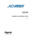
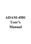
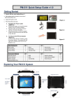
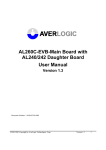
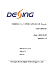
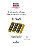
AL37219C-EVB-A2-User Manual-1.1-20090327 AL37219C-EVB-A2 Evaluation Board User Manual Version 1.1 INFORMATION FURNISHED BY AVERLOGIC IS BELIEVED TO BE ACCURATE AND RELIABLE. HOWEVER, NO RESPONSIBILITY IS ASSUMED BY AVERLOGIC FOR ITS USE, OR FOR ANY INFRINGEMENTS OF PATENTS, OR OTHER RIGHTS OF THIRD PARTIES THAT MAY RESULT FROM ITS USE. NO LICENSE IS GRANTED BY IMPLICATION OR OTHERWISE UNDER ANY PATENT OR PATENT RIGHTS OF AVERLOGIC. DOC Number:1-M-PAE319-0201 ©2008-2009 Copyright by AverLogic Technologies, Corp. AL37219C-EVB-A2-User Manual-1.1-20090327 Version and Amendments Date Version Comments 2008.06.27 1.0 Public Release 2009.03.27 1.1 English Grammar Review Author Alvin Liu Disclaimer THE CONTENTS OF THIS DOCUMENT ARE SUBJECT TO CHANGE WITHOUT NOTICE. AVERLOGIC TECHNOLOGIES RESERVES THE RIGHT TO MAKE CHANGES WITHOUT FURTHER NOTICE TO ANY PRODUCTS HEREIN TO IMPROVE RELIABILITY, FUNCTION OR DESIGN. AVERLOGIC DOES NOT ASSUME ANY LIABILITY ARISING OUT OF THE APPLICATION OR USE OF ANY PRODUCT OR CIRCUIT DESCRIBED HEREIN; NEITHER DOES IT CONVEY ANY LICENSE UNDER ITS PATENT RIGHTS, NOR THE RIGHTS OF OTHERS. CUSTOMERS ARE ADVISED TO CONSULT WITH AVERLOGIC OR ITS COMMERCIAL DISTRIBUTORS BEFORE ORDERING. ©2008-2009 Copyright by AverLogic Technologies, Corp. AL37219C-EVB-A2-User Manual-1.1-20090327 Table of Contents 1 Introduction ......................................................................................................1 1.1 Product Description ............................................................................................................ 1 1.2 Package Contents .............................................................................................................. 2 1.3 Block Diagram .................................................................................................................... 2 1.4 Specifications ..................................................................................................................... 2 1.5 EVB Features ..................................................................................................................... 3 2 Quick Setup ......................................................................................................4 2.1 Attach camera (CVBS RCA connector) ............................................................................. 5 2.2 Attach TV monitor (CVBS RCA connector)........................................................................ 5 2.3 Attach power cable............................................................................................................. 5 2.4 Turn on the board power .................................................................................................... 5 2.5 If no video appears … ....................................................................................................... 6 3 Hardware Section.............................................................................................7 3.1 Product Description ............................................................................................................ 7 3.2 Rear Panel I/O Port Descriptions ....................................................................................... 8 3.3 Reset Button....................................................................................................................... 8 3.4 Keypad Panel ..................................................................................................................... 8 4 System Menu..................................................................................................10 4.1 OSD Main Menu............................................................................................................... 10 4.2 Navigating the OSD Menu using the Keypad................................................................... 10 4.3 System Submenu ............................................................................................................. 11 4.4 Channel Submenu............................................................................................................ 12 4.5 PIP Submenu ................................................................................................................... 12 4.6 POP Submenu ................................................................................................................. 13 4.7 Auto Sequence Submenu ................................................................................................ 14 4.8 Time Submenu ................................................................................................................. 14 4.9 Alarm Submenu................................................................................................................ 15 5 Remote Control ..............................................................................................16 5.1 Remote Control Button Description.................................................................................. 16 ©2008-2009 Copyright by AverLogic Technologies, Corp. AL37219C-EVB-A2-User Manual-1.1-20090327 1 Introduction 1.1 Product Description The AL37219 Video Processor EVB is an evaluation product that demonstrates a total solution for video surveillance applications using AverLogic IC chips. This EVB product can receive video streams from up to 9 cameras and can simultaneously display the video on a monitor in a variety of convenient display formats. The main components include three video decoders (AL244) and a video processor (AL37219). The video decoders process 9 channels of analog video, which are converted to digital for video playback by the video processor (AL37219). It is a lowcost, easy-to-install solution for real-time video surveillance applications that need to manage 9-channel video output to TV monitors, VCRs and digital storage devices. The AL37219 video processor provides nine analog CVBS video input connectors. It has cost-effective, high-quality NTSC/PAL video decoding technology with adaptive comb-filter Y/C separation processing. It is also equipped with BCS (Brightness, Contrast, Saturation and Hue) control, Scale-Down Function, Re-play function, Zoom, Freeze, Internal OSD overlay, Motion Detection and PIP/POP display capabilities for monitoring video surveillance devices. ©2008-2009 Copyright by AverLogic Technologies, Corp. 1 AL37219C-EVB-A2-User Manual-1.1-20090327 1.2 Package Contents Please check the package contents and notify any discrepancies or damage to your distributor immediately. AL37219 Mainboard with DC Adaptor 10 RCA cables (CVBS) Power Cord Remote Control Unit User Manual (not shown) 1.3 Block Diagram 1.4 Specifications Video Standard Support: NTSC and PAL Video Input Standard: CVBS Video Output Standard: CVBS ©2008-2009 Copyright by AverLogic Technologies, Corp. 2 AL37219C-EVB-A2-User Manual-1.1-20090327 Display size : Horizontal: 720/720 pixels (NTSC/PAL) Vertical: 480/576 lines (NTSC/PAL) 1.5 EVB Features Manual selection of video standard to adapt to various analog video input standards. High quality adaptive comb-filter for Y/C separation. Multi-window display modes (1/2/4/9). Three embedded TV Encoders with DACS; supports NTSC and PAL standard outputs. Manual adjustment of hue, brightness, contrast and saturation. Individual channel freeze. PIP/POP functionality. Motion detection Internal OSD overlay with programmable bitmap type fonts for OSD display Note: Please note that this is an evaluation product only and not all functional capabilities of AverLogic components are fully demonstrated by this product. Please refer to the AverLogic website (www.averlogic.com) or contact your AverLogic representative (see last page of this document) for more information. ©2008-2009 Copyright by AverLogic Technologies, Corp. 3 AL37219C-EVB-A2-User Manual-1.1-20090327 2 Quick Setup The AL37219-EVB-A2 product installation is fast and easy. In addition to the product packaging contents, you will need to provide a monitor that uses CVBS connections and at least one camera that is also equipped with a CVBS output connector. The setup diagram is shown below: ©2008-2009 Copyright by AverLogic Technologies, Corp. 4 AL37219C-EVB-A2-User Manual-1.1-20090327 2.1 Attach camera (CVBS RCA connector) First attach your camera to one of the nine video input connectors on the rear panel. Turn on the camera and begin transmitting video. 2.2 Attach TV monitor (CVBS RCA connector) Attach your monitor to the monitor connector located on the rear panel (as shown). Turn on your monitor. 2.3 Attach power cable Attach one end of the power cable to the adapter and the other end to a wall socket with the appropriate voltage. Note: The power adapter should already be attached to the mainboard when you receive the product. 2.4 Turn on the board power Toggle the power switch, which is located on the main board near the power adapter connector. A yellow-green LED next to the power switch will illuminate. ©2008-2009 Copyright by AverLogic Technologies, Corp. 5 AL37219C-EVB-A2-User Manual-1.1-20090327 Your monitor should soon begin to display the video images that your camera is transmitting in one of the display boxes on the screen. 2.5 If no video appears … Make sure that all power cables are securely fastened (for monitor, camera and board). Make sure the RCA connection between monitor to board is secure. Make sure RCA connection between camera and board is secure. Make sure that the monitor is in working order. Make sure that the camera is in working order and is delivering video. Make sure that the video standard (NTSC or PAL) used between camera and board is the same (to check board video standard, refer to the Systems Menu section – Systems Submenu). ©2008-2009 Copyright by AverLogic Technologies, Corp. 6 AL37219C-EVB-A2-User Manual-1.1-20090327 3 Hardware Section 3.1 Product Description This product consists of a Mainboard and Keypad Panel. A Power Adapter and cables are also supplied. The only components on the Mainboard to note are the Power Switch, Power connector, Reset Switch and the Rear Panel connectors. Keypad Panel ` Reset Switch Power Switch Mainboard Power Adapter Connector Power-On LED Indicator Rear Panel Rear Panel Note: The jumpers and connectors on this EVB board that are not described are either disabled or not meant for use. ©2008-2009 Copyright by AverLogic Technologies, Corp. 7 AL37219C-EVB-A2-User Manual-1.1-20090327 3.2 Rear Panel I/O Port Descriptions The rear panel contains input and output connectors for cameras and monitors. Rear Panel Connector CH1-CH9. MON. Description These connectors are CVBS connectors designated for video input from up to 9 cameras This connector is an output connector for a monitor with a CVBS line 3.3 Reset Button In the event the EVB has entered an unstable state, you can press the reset button (marked SW2 on Mainboard) to reset the EVB. 3.4 Keypad Panel ©2008-2009 Copyright by AverLogic Technologies, Corp. 8 AL37219C-EVB-A2-User Manual-1.1-20090327 Key UP/FULL ENTER/PIP DOWN/3x3 LEFT/POP Function This key has two functions. It serves as the “Up” navigation key on the OSD menu. Otherwise, you can press this key at anytime for Full Screen video camera display. The default camera for this button can be configured in the POP section of the OSD menu. This key has two functions. It serves as an “Enter” key on the OSD screen (i.e drill down to a submenu or move up to the Main Menu). Otherwise, you can press this key at anytime to enter PIP (picture-in-picture) display mode. PIP display mode is configured from the OSD menu (see OSD Main Menu. PIP submenu). This key has two functions. It serves as a “Down” navigation key on the OSD menu. Otherwise, you can press this key anytime to enter the 9-channel display mode which is a 3x3 array displaying video from 9 cameras. This display can be configured in the POP submenu of the OSD menu (item 9CH). This key has two functions. It serves to flip (backwards) through the available selections of an option on the OSD submenu. Otherwise, you can press this key at anytime to display the POP (picture-on-picture) display mode. You can configure the POP screen from the OSD menu. This key has two functions. RIGHT/QUAD MENU It serves to flip (forwards) through the available selections of an option on the OSD submenu. Otherwise, you can press this key at anytime to access the Quad Display Screen which displays video from 4 cameras. This display can be configured in the POP submenu of the OSD menu. This key allows you to enter and exit the OSD menu FREEZE / RIGHT SHIFT This key has two functions. First, it serves as a tab key when navigating to different fields in an OSD submenu line. Otherwise, this key allows you to freeze all video on the display screens. ZOOM This key allows you to zoom-in on the video image in any display mode. The zoom scaling goes from x1 to x2 to x4 to x8 and then back to x1. SEQUENCE/ LEFT SHIFT CAM1-CAM9 CAMPB The Auto Sequence button is used to automatically display images from different cameras in sequence, one after the other, in full screen mode. The Auto Sequence camera images to be displayed can be configured in the OSD menu (Auto Sequencing). These 9 keys are associated with the 9 cameras that can be attached to this board. When you press one of these keys, the full screen video image from the associated camera will display. Reserved for future use ©2008-2009 Copyright by AverLogic Technologies, Corp. 9 AL37219C-EVB-A2-User Manual-1.1-20090327 4 System Menu 4.1 OSD Main Menu You can bring up the OSD (On Screen Display) Main Menu by pressing the MENU key on the Keypad panel. The OSD screens are used to configure various aspects of the mainboard and display screens. MAIN MENU SYSTEM CHANNEL PIP POP AUTO SEQUENCE TIME ALARM 4.2 Navigating the OSD Menu using the Keypad Once you have entered the OSD Menu, you can use the Keypad Panel to navigate the menu and submenus. Navigation keys are explained below: Key Function ENTER Key This key is used to drill down into a submenu or exit from a submenu. MENU Key This key is used to initially bring up the OSD main menu. This key is also used to exit from the OSD menu. UP/DOWN Keys These keys are used to move up and down the menus. FREEZE Key This key is used as a Tab key to move forward (horizontally) through the different option fields of a configuration line item. This only applies to configuration line items that have more than one field. Sequence Key This key is used as a Tab key to move backward (horizontally) through the different option fields of a configuration line item. This only applies to configuration line items that have more than one field. LEFT/RIGHT Keys These keys are used to flip through the different selections for an option field (RIGHT-forward, LEFT-backward). ©2008-2009 Copyright by AverLogic Technologies, Corp. 10 AL37219C-EVB-A2-User Manual-1.1-20090327 4.3 System Submenu The System configuration screen allows you to set general, system related options. As with the Main Menu, you can use the UP/DOWN keys to highlight the configuration item you want to configure. Then use the LEFT/RIGHT arrow keys to flip through the different options for that item. SYSTEM BORDER VIDEO FORMAT MIRROR FLIP SYSTEM RESET YELLOW NTSC OFF Option Border Video Format Mirror & Flip Settings System Reset Description Allows you to change the screen border line color. Options: White, Gray,Yellow, Red Sets the Video Standard used by this board. Options: PAL or NTSC. You may have to power down or press the Reset button for the change to take effect. Sets the orientation of image on the screen. Options: F – is a vertical flip (upside down) M – horizontal flip (mirror image) MF – both horizontal/vertical flip OFF – Normal Status Press the LEFT or RIGHT key to reset the system. All OSD options will be reset to their original manufacturer settings You can press the ENTER button to return to the OSD Main Menu or you can press the MENU button to exit the OSD entirely (in both cases, your changes will be saved). ©2008-2009 Copyright by AverLogic Technologies, Corp. 11 AL37219C-EVB-A2-User Manual-1.1-20090327 4.4 Channel Submenu The Channel submenu in the Main Menu allows you to configure Contrast, Brightness and Saturation for each Channel. You can use the UP or DOWN key to select and highlight a channel. Then press the FREEZE key to tab through the three option fields (Con, Bri, Sat). Once you have highlighted a field, you can use the LEFT or RIGHT keys to adjust the value. This Evaluation Board only displays configurations for 6 of the 9 channels (i.e. for demo purposes only). CHANNEL CH CON BRI SAT Channel1 Channel2 Channel3 Channel4 Channel5 Channel6 32 32 32 32 32 32 08 08 08 08 08 08 32 32 32 32 32 32 4.5 PIP Submenu The PIP submenu allows you to configure the PIP (Picture-in-Picture) display mode. PIP mode is basically 4 smaller windows (each showing a camera image) that are overlayed on the default full screen camera display (configured in the POP submenu). The PIP submenu is shown below. You can press the UP or DOWN key to select one of the four PIP windows. Then use the FREEZE key to tab through the option fields for that window. PIP MODE SW CH PIP 1 PIP 2 PIP 3 PIP 4 ON ON ON ON 1 2 3 4 ©2008-2009 Copyright by AverLogic Technologies, Corp. 12 AL37219C-EVB-A2-User Manual-1.1-20090327 The option fields are explained below. Option Description PIP1 – PIP4 represent the 4 windows available on the PIP display screen. Mode SW This switch will either turn ON/OFF the display for that PIP window. CH Selects the camera to be displayed in the PIP window. 4.6 POP Submenu POP display screen shows different camera video images displayed side-by-side in separate windows. The available POP menus include: 9CH - 9 channel QUAD - 4 channel POP - 2 channel FULL - Single channel Once you are in the POP submenu (shown below), you can use the UP or DOWN keys to access one of the display modes (e.g. Quad). Then use the FREEZE key to tab through the different windows for that mode (e.g. Quad mode will have 4 windows). Then use the LEFT or RIGHT keys to select the camera to display in that window. POP MODE WIN1 2 4 5 6 7 9CH QUAD POP Full 2 4 5 6 2 3 4 2 7 8 1 1 1 1 8 9 9 ©2008-2009 Copyright by AverLogic Technologies, Corp. 13 AL37219C-EVB-A2-User Manual-1.1-20090327 4.7 Auto Sequence Submenu The Auto Sequence function allows you to automatically display video from different cameras in sequence, one after the other, in full screen mode. The Auto Sequence camera images to be displayed can be configured in this OSD menu item. Once you have entered the Auto Sequencing sub menu, use the UP/DOWN keys to select between the two configuration line items. AUTO SEQUENCE AUTO SWITCH SEQUENCE TIME 1234F678F 10 Sec. Option Description Auto Switch The nine option fields in this configuration item represent the nine cameras in order (1-9). Use the FREEZE key to tab through the 9 camera fields. If you want a particular camera image to be included in the Auto Sequence display mode, toggle the camera’s option field from “F” to the camera number. Sequence Time This represents the time interval, during Auto Sequencing, before changing to the next camera in sequence. Use the LEFT or RIGHT keys to adjust the time interval. 4.8 Time Submenu The Time Submenu allows you to set the date and time for the board. Use the UP/DOWN keys to toggle between Date and Time. Once you have highlighted the configuration line item (Date or Time), use the FREEZE key to tab through the different option fields (e.g. YY, MM or DD). Once you have highlighted a specific field, use the LEFT/RIGHT keys to adjust the field. TIME DATE TIME 08:02:20 12:05:48 ©2008-2009 Copyright by AverLogic Technologies, Corp. 14 AL37219C-EVB-A2-User Manual-1.1-20090327 4.9 Alarm Submenu This product is capable of detecting Video Loss and Motion. You can turn on/off these functions in this submenu. ALARM Video Loss Motion Detect ON OFF The options for this submenu are explained below: Option Description Video Loss When this option is turned ON, the product senses when there is loss of picture for any channel and then it will change the label for that camera on the monitor display from “CH0X” to “CHXL” (e.g. CH03 to CH3L). Motion Detect Alarm This option turns on/off the Motion Detect function. Use the LEFT/RIGHT keys to turn this function on and off. When this option is turned on, motion can be detected in any of the cameras. Flashing square dots will show on all screens and become increasingly dense as it detects more movement. Note: This demo version will apply the dots on all screens, regardless of which camera video the motion was detected on. ©2008-2009 Copyright by AverLogic Technologies, Corp. 15 AL37219C-EVB-A2-User Manual-1.1-20090327 5 Remote Control 5.1 Remote Control Button Description This product comes with a convenient Remote Control unit that allows you to control the AL37219 board without having to use the board’s keypad. The Remote Control keypad is similar to the board keypad but with some functional differences. Key Up Arrow Down Arrow Left Arrow Right Arrow Function Serves as the “Up” navigation key on the OSD menus/submenus. Serves as the “Down” navigation key on the OSD menus/submenus. Serves to flip backwards through the available selections for an option. Serves to flip forward through the available selections for an option. Select Used to drill down to a submenu on the OSD menus or to tab through the different columns on a submenu line. MENU This key allows you to enter and exit the OSD menu Freeze Freezes the video images on all screens. ZOOM This key allows you to zoom-in on the video image in any display mode. The zoom scaling goes from x1 to x2 to x4 to x8 and then back to x1. PIP Displays 4 camera images onto 1 large camera image, which is the “FULL” camera selection in POP submenu. Buttons 1-9 These 9 keys are associated with the 9 cameras that can be attached to this board. When you press one of these keys, the full screen video image from the associated camera will display. FULL Shows POP screen, which is the 2-Panel camera display. FUNC Shows 4-Panel (Quad) camera display MODE Shows 9-Panel camera display Esc Serves to move backward or move up from Submenu to Main Menu on the OSD screens Note that all other buttons on the remote controller that were not mentioned are either disabled or not intended for use. ©2008-2009 Copyright by AverLogic Technologies, Corp. 16 AL37219C-EVB-A2-User Manual-1.1-20090327 CONTACT INFORMATION AverLogic Technologies, Corp. E-Mail: [email protected] URL: http://www.averlogic.com ©2008-2009 Copyright by AverLogic Technologies, Corp. 17