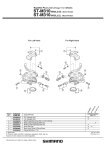
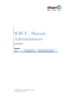
1
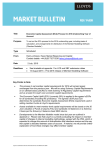
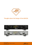
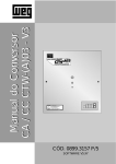
User manual LRS & ULRS V2 series RXRC11xV2 869-903 MHz Digital Receiver 8ch-12ch Radio control FPV & UAV RC Systems V: 2.10 9-11-2009 INDEX Introduction 3 RXRC11xxV2 series. features general 4 RXRC11xxV2 Series with OSD644DMDG 9 Update Firmware (program) receiver 11 RXRC11HV2 specification. Red Series 5 to 12Km 13 RXRC11ULPV2 specification. Green Series 12 to 22Km 14 RXRC11PV2 specification. Blue Series 18 to 72Km 15 RXRC11ULRSV2 specification. Series ULRS violet 70 to 172 km 16 Connects receiver 17 Example Glider Receiver Mount PRO for FPV 19 Getting started receiver 20 Programming Fail Safe 21 (Link) liaison with issuer or programming canal RF 22 SPPM (Serial PPM) en CH10 23 Analog Output RSSI in CH11 24 Internal receiver sensors 25 Compatible transmitters 26 Antennas 28 Compatibility with video de 1.2Ghz 29 ABOUT THIS MANUAL East Manual is not only a translation. Has been written to help the owner. There are many pages with information, procedures, examples, schemes, explanations, configurations and settings. For make the best use of recipients, please read this manual sincerely, along with the OSD644DMDG manuals and the LRS system. El LRS system is not a toy . It is important that you read and understand the extent possible this manual . The manual authors are designers LRS (Long Range System) system. Experienced aeromodelist since 1980. So you have the first-hand information. Can write about errors or suggestions the LRS system or this manual to [email protected]. DMD reserves the right to change of devices or specifications detailing anytime and without prior notice. Check If there are newer updates in www.dmd.es on the page of the product, news or page downloads. Can buy the LRS computers and accessories at http://tienda.dmd.es and distributors authorised. To more information and frequently asked questions, visit www.dmd.es, http://foro.dmd.es www.aeromodelismovirtual.com or www.rcgroups.com. or in the forums: Can See videos of real flight and looking for some with instructions for use and implementation in YouTube or www.vimeo.com (TRON FPV), also You can find links to the videos in the last pages of this manual and in www.DMD.es More links in the latest manual page. Nota: Some of these products may be classified as dual-use (civil and military) so its sale is restricted. For more information send email to [email protected] or contact by phone with the service to the client. RXRC11xV2 series Thank you by purchasing one of the most advanced receivers to radio control of the market. The RXRC11xV2 digital receivers are part of the well-known DMD LRS "Long" system "Range system" to 869-903 Mhz and used in advanced radio control aircraft, Helicopters, cuadracopters, Optocopters, terrestrial or amphibian, car robots, UAV (Ummanned Aerial Vehicle) and FPV (First Person View) or flight in first person. The LRS V2, series receivers are of equal size and weight. Have the connections in the same order and the antenna connection SMA. Differences are basically the range (from 5 to 172Kms), leaked RF and the amperimeter internal or digital altimeter internal. Have the most advanced technology of RF and microcontrollers last generation, similar to the mobile telephones and characteristics of high-end allowing some incredible range with a very high security the radio link. Unthinkable just three years ago. Compatible with video TX 1.2Ghz, 2.4Ghz and 5.8Ghz , except for the RXRCHxxV2 (series) (red) are not compatible with video transmitters 1.2Ghz. Small and powerful. Only 46 x 32 x 20 mm in size allows you to put it comfort in any site or models with space reduced. Light. All capabilities and features a weight of only 22 grms make who have this receiver, enjoyment of a small centre of communications in your model. Broad range models receptor LRS V2, which cover most needs. LRS (Long Range System). From 5 to 172 km . Scope reliably available ranging from 5 the 172 km according to models and employed antennas. A range for all the needs. (Tested physically until 26 km). Sensors internally, Optional according to models which include internal amperimeter up to 30Amps, internal digital altimeter and variometer 0 to 20,000m temperature compensed with a resolution of 10 cm to 8Hz refresh. These receptors enable deleting the OSD in models for FPV & UAV and pass it to the base station on land, simplifying the maximum installation, cabling, weight and space in the model, sending the telemetry station basis with sensors including. Sensors external, optional. Connection through configurable channels or RCBus. Amperimeters of 50, 100 and 130Amp. Altimeter_1A, stabilizer flight, IMU, etc. Connection GPS live or from the RCBus. Removing the OSD on the model and sending the telemetry directly. RXRC11xV2 series. General characteristics. New module WM11500 RF high-end , RXRC11PV2 receivers (PRO), RXRC11ULPV2 and RXRC11UADV2 . It is one of the most advanced and small the market . More sensitivity, high quality and stability until 170 km range, LNA, PA and RF included and RF attenuator and filters in most models. With a size of 25.4x25. 4x3mm circuit fiber quality, class 5, multi-layered, SMD technology and with selected ultraminiature components of the best brands in the market. Compatible pin to pin modules WM11, crystals and used filters have a great precision and stability with the temperature and time. This is necessary to ensure radio links to great distances with reliability and security in the time. Nota: Some of these products may be classified as dual-use (civil and military) so its sale is restricted. For more information send email to [email protected] or contact by phone with the service to the client. New module of RF WM11RC+, RXRC11HV2 receivers with a new microcontroller with double the memory and new compatible RF chip with the previous but with further benefits, keeping more sensitivity, largest range and including RF attenuator. The Crystals of precision and high stability ensure a radio with quality and reliability. Two-way(Receiver and emitter to the simultaneously). They are ready to receive proportional control, data and transmit data and telemetry to base station. La Band RF used is the ISM (industrial scientific and medical) European to 868-870 MHz and 902-928 MHz for ISM in other countries. This often allows use acceptable for an model aircraft small antennas and be very efficient at the same time. The ISM band isn't saturated as the 2.4Ghz and allows a peace of mind using. Modulation FSSH or channel fixed. As the firmware and configuration, can receive in a fixed channel between 19 channels (backward compatible with V1) or use FFSS (frequency hopping) in 10 simultaneous channels. This system is virtually immune external interference and very secure. Enabling secure flight of several pilots at the same time, in the same area with the system LRS. Addressing IP, similar to Internet Protocol. Each receiver and transmitter have a direction unique IP written in factory. A receiver can be bound to a single transmitter filtering your IP address or multiple whether are included in the list of internal authorized computers. Protocol Unibus11WRC. 6Th generation, very tested and stable for more than 10 years. With messages digital and a very elaborate bit that error correction system you provides great security in receipt of data, free of interference. A unique word of 32 bits of the data packet triggering and a checker redundancy (CRC) Cyclical 16 bits per package, do not leave Enter packages with data on bad state. 9 RC channels. Capable of commanding 9 proportional standard servos and 3 auxiliary channels of i/o configurable. Outputs for servos protected against short circuits and voltages unforeseen. 7 channels auxiliary. Configurable. Outputs servo, digital, tickets digital and analogical with various functions for customize the receiver optimally your needs without increasing the wiring and a minimum space and weight. Up to 24 RC channels. You can extend the proportional RC channels for servos of the receiver with the module AMPRC up to 24 channels (future option) and will be available from channels with switches electronic. Redundant Receivers. This planned connect two redundant receivers in parallel and connect them to a module par AMPRC increase security in the event of failure to Professional UAVs. 40Hz Refresh. Data for the servos are updated to 40Hz, speed enough to control of quick and helicopters Output SPPM (Serial PPM), compatible with paparazzi and Microkopter. Exclusive RCBus connectors RC data bus standard, allows these receptors communicate digitally with other modules of the system as the OSD644DMDG (On Screen Display + GPS), the unit of measurement sensors inertial IMU6DMD and future modules. You can connect to PC with the BootADMD and update the memory, programs and settings from PC receiver RXRC11xV2 series. General characteristics. Control from one or more stations or station and PC. You can bind the receiver with a single station or allow PC, and several radio stations can control it receiver. It's useful in case of distant flights or to have redundant issuers by Security. To bind a station or base station, you can use a PC or the pushbutton supplied together with a OSD644DMDG or the receiver LED. WFT-09 of Wfly with a two-way LRS module transmitter to 869-903 MHz is the ideal complement to the control of the pilot. Port trainer is free for traditional use or for a Head tracker for control of the movement the video camera pilot with the position of the head. PC Control. Stations base are prepared for their connection to computer, eliminating the traditional RC station and allowing the use of Joysticks, GamePads or any future compatible periferic. The drivers for PC, have communication TCP-IP, so you can multiple network configurations or work as part of programmes party for control of UAV. Control from FlyStation. Compatible with future models of flyStation. The FlyStation enables interaction pilotUAV that cannot be achieved with traditional, because you have multiple radio buttons and controls additional a provision allowing control of flight economic and the future selection controls and parameters in the OSD644DMDG, as well as the observer camera control in complex systems. You can mix control from a traditional for the pilot station and one flystation for the observer or controls combined from your PC with and without Joystick. RXRC11xV2 series. General Features. Exclusive filtering RF ISM band models PRO and ULTRA. Receivers RXRC11PV2, RXRC11ULPV2 and RXRC11UADV2, have filters becomes band with attenuations of 40 to 80dBm (equivalent to more than 10,000,000 times) frequencies outside the band . Fly without interference in highly saturated communications places of radio or close to repeaters with high powers. This feature is unique in radio receivers LRS control. You can use video 1.2Ghz (No in red series), 2.4Ghz and 5.8Ghz with the very next antennas. Best Behavior to EMI (electromagnetic interference). LRS, receivers are much less sensitive than the of 35 MHz, electromagnetic interference caused by the regulator and the electric motor, as well as their own or other external radio emissions transmitters of video of the model . Proportional Control of RF power, PWRTX - Auto. Refined transmission system with control proportional power RF, enables a dynamic of the radio link exceptional without saturating receivers when they are near the emitter, giving the system a great security. RF electronic and programmable attenuator , serves to increase even more the dynamic, reliability and security of the RF link and prevent situations of blocking RF Receiver, either by excess power emitted at the transmitter own by RF emitted by other computers outside. Digital RSSI + % frames+ noise RF. Combined with the OSD644DMDG, the measurement system quality of reception digital RSSI, calibration to +-1dBm, but the data received OK and RF noise measurement packages indication ambient for channel, allow the pilot quality control at all times of the radio link with excellent and reliable information. At the same time serves to tune the configuration model with reliable data, no errors. You incomparable!. Analog RSSI Output in 10 steps for systems that lack the OSD644DMDG and have RSSI entry for voltage Connection the antenna with SMA female of 10 cm. allowing choice of antenna most adequate and efficient for every need. You can lengthen the connection of the antenna using a flex additional. Flight Stabilizer. Efficient and safe model in flight control by connecting a stabilizer flight infrared (the copilot sensor), the through the RCBus or the auxiliary port . When received data with focused joysticks during more than n seconds, the receiver helps the stabilising the attitude in flight of the model with the references provided by infrared sensor. RC channels do not need extra or wiring extra servos. Control Automatic heading and altitude . If the receiver has a connected GPS directly or a OSD644DMDG, you can automatically control the direction and the altitude model if the pilot left the joysticks at rest more than n seconds. This makes the navigation much easier and frees the pilot of the need to stabilize and continually flying model, to interact with the system by selecting options, making calculations of navigation or simply take a break. (Option according to models and accessories stabilizers). Reduction of the wiring of the servos. Improves security by not requiring electronic modules additional control stabilization or navigation waypoints. The servos are directly connected to the receiver. The receiver of the RCBus is communicates efficiently with the rest of modules of the system, reducing the wiring necessary. Modes RC, FPV, UAV. The receiver prepared internally to work with several modes flight. UAV Mode: Automatic navigation by waypoints. The receiver is ready to connect to the IMU6DMD (inertial measurement unit) with GPS, OSD and the stabilizer flight infrared of RCBus that give you a very simple wiring and security. RXRC11xV2 series General Features. Stabilization Spin. If available IMU, depending on receiver model may be permanently spin stabilized on the 3 axes improving and stabilizing the flight model and softening movements unwanted in the video when you use cameras with large lenses. The IMU provides data for the attitude and moments of rotation of the aircraft and receiver is responsible for stabilizing it, removing extra external giroscopes, RC channels and additional wiring. RTH (Return To Home) or function back home: the receiver can be configured to perform a back home automatic mode UAV, when lost or fails the signal or link of the issuer. The RTH is configurable according to modes of flight and mission programmable at the receiver. Besides great security conferred upon it now use a LRS long-range system have a return home automatically in case of loss of signal or difficulties for flight control. With these combined systems is very difficult to lose the model. Telemetry. Receiver is to its When an issuer and transmits in 869 or 903 MHz with configuration and model, data base on earth station or other aircraft in flight. Data as altimeter, battery levels, GPS among others that allows accurate and reliable monitoring on the ground, as well as positioning geografic model using digital mapoint, Google Earth and OziExplorer map among others. Sending data for the radiomodem 869 MHz as system is much more stable, reliable and has greater range than the transmsion data via video or channel of sound of the video. RXRC11xV2 series. Features General. OSD in flight. The OSD644DMDG is the perfect complement to the LRS V2 receivers. The receiver communicates and feeds the OSD through RCBus, showing the OSD parameters in a HUD type F16 with 4 screens crowd fully configurable by the user. At the same time the OSD you send information to the receiver to control the model mode UAV or assisted and send data of telemetry land. OSD in land. With some models of receiver and depending on the combination of modules in the model, is no longer required in the model OSD644DMDG (On Screen Display) in FPV mode. Some receiver models have included altimeter and amperimeter. Which do not include can expand with small modules through RCBus or use included in the IMU6DMD. The having telemetry receiver can send data to the base station with terrestrial OSD. By a side if fails the video OSD in land can maintain and generate data in the screen, on the other hand is more economical if you have multiple aircraft, is reduced the risk of losing valuable OSD in case of strong coup or lost. Redundant OSD. Simultaneously OSD can be used in the model and land to increasing security on UAVs professionals. RXRC11xV2 series. Features General. Fail Safe. Programmable from PC or with the supplied pushbutton, conecting it CH12, by the OSD644DMDG or the receiver LED. Note: No Use this receiver in the model final, if not configured correctly Fail safe. Radio beacon included in the receiver. Greater security against a possible loss of the model. If the receiver enters Fail Safe, unable to return home automatically (RTH) and the model is lost, the receiver is as a Radiobaliza in channel 19 sending the GPS position (if you have connected the OSD644DMDG). To facilitate the model search. This system aims to augment or supplement security in case of lost but replaces the greater security of a radiobaliza independent, since in some cases of sudden fall, the receiver is disconnected batteries by the impact and its radiobaliza is not useful. Radio beacon external RDB2. (In development). The independent radio beacon RDB2, can be connect to the RCBus for informating the position of the equipment by GPS in the channel 19., allowing multiple features new. Radar, Locator. In the future there will be an option before a receiver can locate another plane with the RDB2 radio beaconand communicate with the time real, exchanging data. This will let you search for lost by radio models in flight and determine the position on other aircraft systems flight supported, such as a radar if it were. RDB1 external Radio beacon. An economical alternative to locate the computer is to use the radio beacon independent RDB1. To locate the computer you can use a RadioModem Wlink11 with a PC or terminal WMan11. Available kit Locator. Connection direct to PC. In via RCBus with the BootADMD for configuration in land or for control board in advanced UAVs computer Based. Power supply from 3.3 to 6Vcc. When a receiver connected to the OSD644DMDG, the power supply must be Stabilized 5Vcc (DCDC or BEC). The voltage input has a filter receiver LC and linear regulator of low drop (LDO) of 3V. Watchdog of 0.1 seconds and a detector low voltage power (1.8V) leave no room for unplanned system downtime. RXRC11xV2 series. General characteristics. BootADMD. Update of firmware and configuration of the receiver. All models include the BootADMD system, a charger Updater firmware (program of the microcontroller) by USB to PC to update its receiver in at home with the latest advances and developments that may have in these models and begin to be available on our web www.dmd.es. BootADMD-USB Software for Windows BootADMD RXRC11HxxV2 Models. Series red. 5 to 12 km Economic, the hobby-oriented. Distinguished by the red label: Specification Range: Power: Sensitivity: Attenuator: RF band: Frequency: Filters RF: System: Modulation: Module RF: Telemetry: Channels RC: Output antenna: Soda PPM: Power: Fail Safe: Dimensions: Weight: Gearbox: Updatable: Transmitter: Bidirectional from 5 to 12 km. @ 10mW. + 10dBm (10mW). -107dBm @ 90 % packages ok. If.18dBm Max.In steps of 6dBm BWI dual. Select Automatic. 868-870 MHz (Europe) and 902-904 MHz (other countries) No. Unsupported video 1.3Ghz. 100Khz 38 kb. GFSK. FFHH 10CH. WM11RC + If. + 10dBm (10mW). 9 for proportional standard servos + 3 various connectors uses 10 cm SMA female flex. 40Hz 5.0V.Min 3.3V. Max 6.5Vcc programmable 46 x 32 x 20 mm 22 grams Plastic ABS. If.Upgradeable firmware with BootADMD of the RCBus TX11MFLRS-10-1 (869 MHz) Europe TX11MFLRS-10-2 (903 MHz) rest countries References: RXRC11HV2 Receiver 869-915 MHz standard. 9ch. - 107dBm @ 90 % 10mW telemetry. RXRC11HAMV2 Receiver 869-915 MHz. 10mW telemetry. + Amperimeter 30A integrated in to the same size. RXRC11HADV2 Receiver 869-915 MHz standard.10mW telemetry. + Amperimeter 30A integrated into the same size. + altimeter and digital precision 0-20 variometer. 000 m (trade-off temperature, 9Hz, 10 cm resolution) prepared for RC sailboats traditional or FPV. Module transmitter TXMFLRS-10 Appropiated for the receiver RXRC11ULPxxV2 models. Green series. 12 to 22 km Double range with low power, professional applications and hobby. Distinguished by the green label: Specification: Range: Power: Sensitivity: Attenuator: Band RF: Frequency: RF filters: System: Modulation: Module RF: Telemetry: RC channels: Output antenna: Refresh PPM: Power: Dimensions: Weight: Gearbox: Updatable: Transmitter: Bidirectional 12 to 22 km. @ 10mW. + 10dBm (10mW). -115dBm @ 90 % packages ok. If.18dBm Max. steps in 6dBm BWI 869 MHz Europe BWI 903 MHz rest countries. 868-870 MHz Europe and 902-904 Mhz. If. -TX, 40dBm -80dBm RX. Compatible video 1.3Ghz. 100Khz 38 kb.GFSK. FFHH 10CH. WM11500LP If. + 10dBm (10mW). proportional 9 for servos 3 uses various connectors 10 cm SMA female. 40Hz 5.0V. Min 3.3V. Max 6.5Vcc 46 x 32 x 20 mm 22 grams ABS plastic. If. Upgradeable firmware with BootADMD of the RCBus TX11MFULRS-500 (869 MHz) Europe TX11MFULRS-500-2 (903 MHz) rest countries References: RXRC11ULPV2 RXRC11ULPV2-2 Receiver 869 MHz (Europe) Double range. 10mW telemetry. Receiver 903 MHz Double range.10mW telemetry. RXRC11ULPADV2 Receiver 869 MHz (Europe) double range 10mW telemetry. + Amperimeter 30A + altimeter and digital variometer of precision 0-20. 000 m (temperature compensation, 9Hz, 10 cm resolution) prepared for traditional RC sailboats or FPV. RXRC11ULPADV2-2 Receiver 903 MHz double range 10mW telemetry. + Amperimeter 30A + altimeter and digital variometer of precision 0-20.000 m (temperature compensation,9Hz, 10 cm resolution) prepared for traditional RC sailboats or FPV. Module transmitterTX11MFULP-500suitable for receiver RXRC11PxxV2 models. Series blue. 18-72 km Long-range, professional applications and advanced hobby. Distinguished by the Blue label: Specification: Range: Power: Sensitivity: Attenuator: Band RF: Frequency: RF filters: System: Modulation: Module RF: Telemetry: RC channels: Output antenna: Refresh PPM: Power: Dimensions: Weight: Gearbox: Updatable: Transmitter: Bidirectional 18 to 72 km. @ 500mW. + 27dBm (500mW). -105dBm @ 90 % packages ok. If.18dBm Max. steps in 6dBm BWI 869 MHz Europe INCOME 903 MHz rest countries. 868-870 MHz Europe and 902-904 MHz. If. -TX, 40dBm - 80dBm RX. 100Khz 38 kb. GFSK. FFHH 10CH. WM11500LRS If. + 27dBm (500mW). 9 for servos standard proportional 3 uses various connectors 10 cm SMA female. 40Hz 5.0V. Min 3.3V. Max 6.5Vcc 46 x 32 x 20 mm 22 grams ABS plastic. If. Upgradeable firmware with BootADMD of the RCBus TX11MFULRS-500 (869 MHz) Europe TX11MFULRS-500-2 (903 MHz) rest countries References: RXRC11PV2 RXRC11PV2-2 Professional Receiver 869 MHz (Europe) 500mW telemetry. Professional Receiver 903 MHz. 500mW telemetry. RXRC11PADV2 Professional Receiver 869 MHz (Europe) 500mW telemetry. + Amperimeter 30A + altimeter and digital variometer precision 0-20.000 m (temperature compensation, 9Hz, 10 cm resolution) all within the same enclosure. RXRC11PADV2-2 Professional Receiver 903 MHz. 500mW telemetry. + Amperimeter 30A + altimeter and digital variometer precision 0-20.000 m (temperature compensation, 9Hz, 10 cm resolution) all within the same cash. ModuletransmisorTX11MFLRS-500 suitable for receiver RXRC11UADV2 models. Violet series. ULRS. 70 to 172 km Ultra long-range, professional, special applications and defence. Distinguished by the Blue label: Nota: These modules can be classified as dual use (civil and military) for sale is restricted. For more information send email to [email protected] or contact by phone with service to the client. Specification: Range: Power: Sensitivity: Attenuator: Band RF: Frequency: RF filters: System: Modulation: Module RF: Telemetry: RC channels: Output antenna: Refresh PPM: Power: Dimensions: Weight: Gearbox: Updatable: Transmitter: Bidirectional 70 to 172 km. @ 500mW. + 27dBm (500mW). -115dBm @ 90 % packages ok. If.18dBm Max. steps in 6dBm BWI 869 MHz Europe BWI 903 MHz rest countries. 868-870 MHz Europe and 902-904 MHz. If. -TX, 40dBm - 80dBm RX. 100Khz 38 kb. GFSK. FFHH 10CH. WM11500U If. + 27dBm (500mW). 9 for servos standard proportional 3 uses various connectors 10 cm SMA female catchphrase. 40Hz 3.3 6.5Vcc Max. 46 x 32 x 20 mm 22 grams ABS plastic. If. Upgradeable firmware with BootADMD of the RCBus TX11MFULRS-500 (869 MHz) Europe TX11MFULRS-500-2 (903 MHz) rest countries References: RXRC11UADV2 ULRS Receiver 869-915MHz.. 500mW telemetry + Amperimeter 30A integrated + altimeter and variometer digital precision 0-20.000 m (Compensation temperature, 9Hz, 10 cm resolution), Everything within the same box. The module transmitter TX11MFULRS-500 suitable for receiver Connecting receptor Connections example of LRS transmitter receiver station using Wlfy WFT-09 or FF9 Futaba. In the example cabled only the RCBus in the OSD644DMDG and as an example the measurement of the battery in the OSD644DMDG. You can add a connection channel 5 of the receiving the entry change of page to the OSD644DMDG. In future releases firmware will not be necessary since the change of page of the OSD and new ones functions take place on the RCBus. The values of the regulator and motor they are a PRO Glider. Connecting receiver Power: 5V typical, (min 3.3V, Max 7V). Consumption receiving environment: 15 - 25mA Since from the BEC of controller of the electric motor in the central pin connector servo (3 for WFT-09). From a KYARUSH in a free connector.+ 5V is central pin and opposed to GND pin is used to measure the Bat. You can connect the power of 5V, from Connector 1 to 12. Internal power is filtered for RF, by a subsequently stabilised to 3V LC circuit. Can feed directly from a 4.8V or 6V battery. If the battery is 11.1V LIPO, use an external regulator or a DCDC24/5RC. Pin 1 is in all connectors 0V (GND), pin 2 is + is 5Vcc and pin 3 signal (0 to + 3V) or data. Channels CH1-CH9: 9 servos standard connectors or Digital of radio control. The output signal of the servo is protected against short circuits and power input to 7v. The CH9 can be configured as an outlet for servo 9 or as auxiliary channel. The route of the servos can be set up (not active yet) to increase the camera scans without need to auxiliary electronics , saving cabling, size, weight and cost. If used digital servos or high torque, note into account the current limits of the BEC or DCDC. RCBus: Only for 869 MHz. connector systems 9 If you use a system of 35 MHz or 2.4Ghz radio control standard, is not used. Serves to connect and feed the OSD644DMDG from the receiver and to communicate the receiver with the OSD. From the RCBus can be update the software of the receiver. You need the BootADMD and its software free. If you need to connect more peripherals to the RCBus, you can use a "Y" in RC connectors or use the OSD RCBusfree output. (IMU, etc OSD) peripherals are connected in parallel to the RCBus Speed: 115.200 bauds. We need a female-female cable, for connection of the receiver-OSD. Auxiliary channels: Auxiliary channels they have multiple uses. You can use outputs standard RC (depending on receiver model) digital outputs , digital inputs or entries analogical. Are configurable by the user. Analog measurements, may be for current, voltage, temperature, etc. The digital outputs give a voltage from 0 to 3 volts. The digital inputs or analogical support from 0 to 6V. To measure to 18V put in series R and 2K. Configure channels auxiliary occurs from PC with the BootADMD. (according to firmware version) CH5 servo or auxiliary. Output servo 5 by default. Optionally auxiliary channel. Digital output, digital input or analogical programmable. Entry voltimetro 5V. (setting up and conducting bridge between +5 V and the entrance). CH7 servo or auxiliary. Output servo 7 by default. Optionally auxiliary channel. Digital output, digital input or analogical programmable. CH8 servo or auxiliary. Output servo 8 by default. Optionally auxiliary channel. Digital output, digital input or analogical programmable. CH9 servo or auxiliary. Output servo 9 by default. Optionally auxiliary channel. Digital output, input digital, programmable. Entry RPM. CH10: Assistant. (Especially with higher current) output (to positive) / entry digital or analogical, programmable. Exit SPPM (serial) (PPM). CH11: Assistant. Output / input digital or analogical, programmable. Exit Rssi analogical by PWM with C 10uF. CH12: Assistant. Output / input analogical, programmable. When starts the receiver is used also to configure the setup, using the supplied pushbutton. Antenna: female SMA connector with flex. Use the antenna supplied or compatible to 869 MHz or 903 MHz and 3 or 5dBi at least. The position the antenna in the plane is very important. Make sure that any element make shadows. Example receiver assembly for a Glider PRO for FPV Start-up receiver Digital receivers RXRC11xV2 , behave similarly to recipients radio control 35 or 72 MHz, so no no caution Special. There are a difference in at time of commissioning, because it should be in March the receiver before that station. Don't worry, the outputs of the servos and engine are disabled until the receiver to detect its station.This is necessary only if you use a OSD644DMDG on early versions of firmware since must spend time with the receiver and OSD644DMDG in March and without connecting the issuer, for which the GSP boot and coga satellites. The timeout depends on the model of GPS. About 10 to 20 seconds, in some cases reaching 180 sec is typical. If you need to use OSD without the GPS receiver to adjust its model, it is not need to wait and can put the receiver plug and the station when you appropriate and in the sequence you need. ATTENTION: The first time you connect or try the receiver on a plane or helocopter, take care of connect the engine without blades, could damage unforeseen. Before test for the first time, should schedule the Canal RF or IP identification of the radio station, to work with its station and the position of the servos in Fail Safe. If purchased a kit, it is normal that it is scheduled by factory default and should not schedule the channel. Remember: configure their Fail Safe. Start-up sequence: Station stop. Apply voltage switch or the receiver and OSD battery connector and It is ready to operate. Appear initial messages in the OSD644 and GPS starts searching for satellites. The servos are disabled (no pulse). Wait to the GPS receive several satellites. Put the station launched. If the RF channel or the station identification are correct, will become the servos, the screen is cleared and frames and reception level appear in dBms and data navigation. OSD connect receiver and stop station Check the normal functioning of the servos, motor and perform the same operations adjustment to station with its usual receptor Note that the antenna is installed properly before takeoff. The position of the antenna is very important for a correct reception. A time in flight, you can see the quality of the video coverage glasses (if the) (modality is FPV), which will bring you a great flight safety. Attention: ALWAYS must be connected the antenna of the radio station that is in place. Of otherwise, you can break the module issuing or impair the characteristics of the issuer RF. OSD with the recipient in Active normal, issuing reception Programming Fail Safe ATTENTION: Care with the engine. MAY occasionally discretion damages SI SE makes in progress. The Fail Safe, is programmed with the auxiliary push supplied , connecting it in the CH12, in the time of the launching of the receiver, wherever the station stop. Have your video glasses or monitor since the parameters appear in screen. If not possible, note in the led of the receiver. Stop the station. Launch the receiver. The led will be on or off according to the version of the receiver. Press the rear receiver button to enter mode setup or configuration. The led fixed power will be. A time within the setup, press the button again and the "Fail" option appears "Safe", press the button while appears (intermittent led 0.3seg) as to the two seconds returns to the menu. A time within the Fail Safe configuration (intermittent led more slow), turn on the radio station at low power, he is immediately displayed in the video glasses all servos position values. Values positions servos: minimum = 70, Center = 150, maximum = 230 Adjustment the position of the servos as desired that they remain Fail Safe Press the button. The end. Fail safe is already scheduled. If you did not station in March not program the fail safe, disconnect the receiver to finish. By Security subsequently verify that programming is correct. Liaison with issuer (Link) or programming channel RF The LRS receivers, in versions earlier than 2.0 need to be set the RF channel in the ICM band. There are 19 channels available. Receivers with frequency hopping, need to bind to the issuer. Each receiver and emitter take recorded a unique IP address that are used to bind the computers. If you purchased a LRS kit, most likely not need to perform this configuration. Can view a sample configuration in http://www.vimeo.com/2995095 video. ATTENTION: BEWARE OF THE ENGINE CAN BE DAMAGED IF OCCASIONALLY LAUNCHES. The channel RF or Link, according to versions firmware is programmed with the supplied helper pushbutton , connecting it in the CH12, at the time of the launching of the receiver, provided that the station is stop. Have your video glasses or monitor since the parameters appear on the screen. If not possible, note in the led of the receiver. Stop the station. Put up the receiver. The led will be on or off according to the version of the receiver. Press the rear receiver button to enter mode setup or configuration. The led fixed power will be. A time within the setup, press the button again and the "Fail" option appears "Safe" (intermittent led 0.3seg), wait 2 sec. that disappear. Press the rear button receiver again to enter mode channel RF (led intermittent fast 0.1seg). Press the button while appears "Channel RF" or blinking fast led, since the two seconds returns to the menu. A time inside the configuration of the RF channel, the led lights fixed a one second and then turns off, make sure that the receiver is performing a scanner of the If you have OSD RF channels. According to the receiver firmware this conduct a scanner changing bandaICM 869 MHz (band 0) 903 MHz (band 1).Also shows the IP address of the recipient. The IP filtering is disabled at the moment (see IP addressing) allowing multiple issuers in the selected channel can command the receiver. Put launched the station high power (if a BTS1-500) and wait for which the receiver detects the RF channel and the ICM band according to versions. If the receiver detects an issuer but reception RF not this at the appropriate level (reception loudly), the shall delibe led a short Flash. A time select channel receiver will automatically from the Setup and will be in normal reception mode and activate the servos. IP filtering will be activated and only its authority may commanding this receiver although other stations they were in the same RF channel. If want two or more stations to command your receiver (is useful in long-hauld for safety or to land at many km from the starting point to another station) is sufficient to re-enter the programming of the channel, wipe IP filtering, not put in place the radio station, simply stop the receiver at this point. For that your receiver is not accidentally linked with another station will only accept stations with high receptions before of saturation (best of - 35dBm). This system has a security if you make this setting in the flight envelope. Is may have to try different positions of the station for which the captures correctly. SPPM CH10 Digital Receivers RXRC11xV2, have an exit SPPM, which makes them very interesting feature output for mounts based in paparazzi and for the cuadracopters and optocopters of Microcopters. There is a LRS receiver Special with SPPM cuadracopters Microdron. Times are 390uSeg for the separator. T1.... T9... Minimum: Neutral: Maximum: 1.0mSeg 1.5mSeg 2.0mSeg Compatible with paparazzi, Microcopter and Microdron Output analog RSSI. CH11 The output RSSI analogical is useful if you do not have the OSD644DMDG. Serves view the coverage of radio receiver. The output this ready to be activated in Channel 11: CH11. the information comes with PWM impulses of 100uSeg in 1000uSeg periods. Output impedance: 10K. Voltage output: 0V to 3V max. Resolution: 10dBm Should be parallel with the output a capacitor from 6.8uF/6.3V to 22uF/16V to convert the PWM pulses in voltage. The final value of the capacitor depends on where the RSSI output to connect. Voltage-dBms table: 0.0V: < - 103dBm or Fail safe 0.3V: > - 103dBm 0.6V: > - 96dBm 0.9V: > - 86dBm 1.2V: > - 76dBm 1.5V: > - 66dBm 1.8V: > - 57dbm 2.1V: > - 48dBm 2.4V: > - 40dBm 2.7V: > - 30dBm 3.0V: > - 20dBm If you need to lower the voltage for the measurement can be a potentiometer 22 K or 10 K or a divisor of the RSSI, with Fixed resistors 22 K and 11 K (10 K + 1 K) for which a voltage from 0 to 1V (dividisor x 3). Internal sensors receiver All the models have internal voltimetre of the RF (3V) module. According to the receiver model may be amperimeter, altimeter and variómeter internal. The internal sensors are intended model at FPV & UAV the receiver do not need to OSD644DMDG in the model and can connect in station base. Saving of complexity, cabling, weight and cost in the model. Amperimeter: sensor current or amperimeter to 30Amp with 35Amp peaks. Useful for electric models with engines up to 300-350W maximum. In gasoline models serves to control consumption electric system. Altimeter and variometer: digital 0 to 20,000 m offset in temperature with a resolution of 10 cm. 8Hz of Refreshment. Compatible table selection receivers an transmitters This table is intended to facilitate the election of his receivers and transmitters. Remember: the models of receivers and transmitters of the same series with the same color label sets are more appropriate and compatible. BootA means upgradeable firmware via the BootADMD. Modules relays compatible For facilitate their selection, receivers and transmitters of the same models series with the same color label sets are more appropriate and compatible. Is use the transmitters and receptors modules with the characteristics of remote control and telemetry range equal, using modules remotely and telemetry transmitters and receivers in the same color label. Not You must mix 500mW computers with 10mW to emergency systems ancient with the BTS1-500, since in the future may be incompatible the firmware versions. La BTS1-500 base station (first teams LRS) and their RXRC11L receivers are compatible with RXRC11HV2, RXRC11HAMV2 and RXRC11HADV2 (red series). The estimated maximum range is 50 to 70 km for remote control and 5 km to telemetry with SMP-918-9 antenna in the BTS1-500. The BTS1-500 base station and RXRC11L receiver are out of production. Base Station BTS1-500 receiver RXRC11L receiver RXRC11HV2 El module transmitter BTX11MFRS-10 is compatible with the RXRC11HV2, receivers RXRC11HAMV2, RXRC11HADV2, RXRC11ULPV2 and RXRC11ULPADV2. The estimated range of remote control RC and the telemetry is 5 to 12 km with RXRC11HV2, RXRC11HAMV2, red series receivers RXRC11HADV2. You can improve the range of remote control RC (not of the telemetry that would be 5 to 12 km) from 12 to 22 km with receivers of green series RXRC11ULPV2 and RXRC11ULPADV2. Module transmitter TX11MFLRS-10 receiver RXRC11ULPV2 receiver RXRC11HV2 Modules compatible transmitters The module transmitter TX11MFULP-10 is compatible with the RXRC11HV2, receivers RXRC11HAMV2, RXRC11HADV2, RXRC11ULPV2 and RXRC11ULPADV2. The estimated range of remote control RC and the telemetry is 12 to 22 km with receivers of green series RXRC11ULPV2 and RXRC11ULPADV2. Module transmitterTX11MFULP-10 Receiver RXRC11ULPV2 Module TX11MFLRS-500 transmitter is compatible with the receivers. RXRC11PV2 and RXRC11PADV2. Early versions firmware of the module transmitter are compatible with the receivers of the Red series and the ancient RXRC11L. In future versions of firmware only will be compatible with the receivers of the series blue. The estimated range of remote control RC and the telemetry is 18 to 72 km with receivers of blue series. RXRC11PV2 and RXRC11PADV2. Module transmitter TX11MFLRS-500 receiver RXRC11PV2 The module transmitter TX11MFULRS-500 is compatible with receivers RXRC11UADV2. The estimated range of remote control RC and the telemetry is 70 to 170 km. Nota: These modules can be classified as dual use (civil and military) for sale is restricted. Module transmitterTX11MFULRS-500 receiver RXRC11UADV2 Antennas ____________________________________________________________________________________ Antennas that needs the LRS system have an impedance of 50 ohms and a frequency band between 867 MHz 869 MHz for ICM European legislation (CE) and 900 to 929 MHz for most of the rest of countries (FCC). ANTGSM900. Antenna omnidirectional 868-928 MHz 5dBi ________________________________________________________________________________________ SMP-918-9. Directional antenna 9dBi 868 to 928 MHz. (optional). Increases the range . Support for 1.2Ghz video receiver Immunity testing LRS 869MHz V1 and V2 video system with 1,2Ghz on all video channels. Tests have been performed with the antenna of reception of the receiver and the transmitter of video to 30 cm. the LRS station 869 MHz metres dimmed to receive in the receiver - 75dBm. Test receiver RXRC11L V1 and RXRC11HV2 (red series): Channel video frequency video attenuation signal reception __________________________________________________________ 1 1078Mhz -27dBm Interferes far 2 1116Mhz -29dBm " 3 1158Mhz -27dBm " 4 1200Mhz -23dBm " 5 1006Mhz -35dBm much worse 6 1038Mhz -27dBm Interferes far 7 1238Mhz -21dBm 8 1279Mhz -18dBm " Interferes too An attenuation of 27dBm media, makes that the receiver need receive at least - 70dBm to not fail safe. With a 10MW LRS system (+ 10dbm) and receiver RXRC11HV2, can not be achieved almost nothing, only a few hundred meters. With a 500mW LRS system (+ 27dBm) (RXRC11L and) (RXRC11HV2), possibly reaching only 3-4 km of the 50 km common. From 5-10meters seems unaffected, so If a fellow flight has 1.2Ghz in his plane while not approaching in flight a plane to another less than 5 meters and still relatively far away, there is no problem. No problem on the ground. Conclusion: Not can be use video systems in 1.2Ghz with RXRC11L V1 receivers and with the RXRC11HV2 (red series). LRS RXRC11ULPV2 systems (green series), professionals (blue series) ultra long and RXRC11UADV2 RXRC11PV2 range (violet series) are not affected by any radio station out the 868 to 870 MHz range. So in case of necessity if it can be used together with video to 1.2Ghz. On systems that if works, l media atenuation for 1.2Ghz is - 1dBm, practically no note is nothing. This is due to the Special RF leading built-in filter. Note: video of 1.2Ghz does not comply with European rules. There are only authorized to video channel amateur licensed. Alternative solution: Use 5.8Ghz video. Solution alternative: Use video in 2.4Ghz on Channel 6 doesn't bother to 2.4Ghz RC transmitters. Verify the frequency Channel 6 this authorized in your country The DMD, team wishes you the best flights For more information and frequently asked questions visit www.dmd.es or in the forums: http://foro.dmd.es/ www.aeromodelismovirtual.com or www.rcgroups.com . You can view videos of real flight and some with use and in http://www.vimeo.com/user519901/videos or commissioning instructions or , YouTube http://www.youtube.com/watch?v=NQlypv91Tuw You can also find links to more FPV with LRS videos at www.dmd.es RXRC11HV2 Design by Tron. Made in Europe . RC Systems C / Federico García Lorca, 5 46136 Museros (Valencia) Spain Phone customer: 615185077 Phone Admin.: 96 1450346 Web: www.dmd.es www.dmdopen.com Emails [email protected] , [email protected], [email protected] Digital Micro Devices 2007, 2008, 2009 The these brands are to title informative, remain the property of their legal registrars. Digital Micro Devices (DMD) makes no warranties about the use of this product to exception of standard guarantees company listed in DMD terms and conditions located on the Web page of DMD. DMD not assumes no responsibility for errors that may appear in this document and reserves the right to change the device or the specifications listed at any time and without notice or It has no commitment to update this information. Do not grant licenses or patent or any other intellectual property of DMD environment the sale of products of DMD, expressly or by implication. Products DMD are not authorized for use as critical components in computers in that depends on the people's lives. DMD declines all responsibility for use the user of this module.