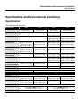
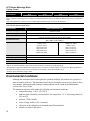
1
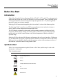
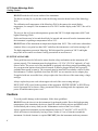
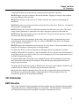
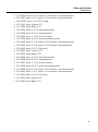
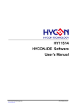
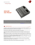
Hart Scientific
917X Series
Metrology Wells
Getting Started
ENG 562201
Limited Warranty & Limitation of Liability
Each Metrology Well from Fluke’s Hart Scientific Division (“Hart”) is warranted to be free from
defects in material and workmanship under normal use and service. The warranty period is one
year. The warranty period begins on the date of the shipment. Parts, product repairs, and services
are warranted for 90 days. The warranty extends only to the original buyer or end-user customer of
a Hart authorized reseller, and does not apply to fuses, disposable batteries or to any other product
which, in Hart’s opinion, has been misused, altered, neglected, or damaged by accident or
abnormal conditions of operation or handling. Hart warrants that software will operate
substantially in accordance with its functional specifications for 90 days and that it has been
properly recorded on non-defective media. Hart does not warrant that software will be error free or
operate without interruption. Hart does not warrant calibrations on Metrology Wells.
Hart authorized resellers shall extend this warranty on new and unused products to end-user
customers only but have no authority to extend a greater or different warranty on behalf of Hart.
Warranty support is available if product is purchased through a Hart authorized sales outlet or
Buyer has paid the applicable international price. Hart reserves the right to invoice Buyer for
importation costs of repairs/replacement parts when product purchased in one country is submitted
for repair in another country.
Hart’s warranty obligation is limited, at Hart’s option, to refund of the purchase price, free of
charge repair, or replacement of a defective product which is returned to a Hart authorized service
center within the warranty period.
To obtain warranty service, contact your nearest Hart authorized service center or send the
product, with a description of the difficulty, postage, and insurance prepaid (FOB Destination), to
the nearest Hart authorized service center. Hart assumes no risk for damage in transit. Following
warranty repair, the product will be returned to Buyer, transportation prepaid (FOB Destination).
If Hart determines that the failure was caused by misuse, alteration, accident or abnormal
condition or operation or handling, Hart will provide an estimate or repair costs and obtain
authorization before commencing the work. Following repair, the product will be returned to the
Buyer transportation prepaid and the Buyer will be billed for the repair and return transportation
charges (FOB Shipping Point).
THIS WARRANTY IS BUYER’S SOLE AND EXCULSIVE REMEDY AND IS IN LIEU OF
ALL OTHER WARRANTIES, EXPRESS OR IMPLIED, INCLUDING BUT NOT LIMITED
TO ANY IMPLIED WARRANTY OF MERCHANTABLILTY OR FITNESS FOR A
PARTICULAR PURPOSE. HART SHALL NOT BE LIABLE FOR ANY SPECIAL, INDIRECT,
INCIDENTAL. OR CONSEQUENTIAL DAMAGES OR LOSSES, INCLUDING LOSS OF
DATA, WHETHER ARISING FROM BREACH OF WARRANTY OR BASED ON
CONTRACT, TORT, RELIANCE OR ANY OTHER THEORY.
Since some countries or states do not allow limitation of the term of an implied warranty, or
exclusion or limitation of incidental or consequential damages, the limitations and exclusions of
this warranty may not apply to every buyer. If any provision of this Warranty is held invalid or
unenforceable by a court of competent jurisdiction, such holding will not affect the validity or
enforceability of any other provision.
ii
Fluke, Hart Scientific Division • 799 E. Utah Valley Drive • American Fork, UT 84003-9775 •
USA Phone: +1.801.763.1600 • Telefax: +1.801.763.1010 • Email: [email protected]
www.hartscientific.com
Subject to change without notice. • Copyright © 2005 • Printed in USA
Table of Contents
Table of Contents ...........................................................................................i
Figures...........................................................................................................iii
Tables ............................................................................................................iii
Before You Start ............................................................................................1
Introduction..............................................................................................................................1
Symbols Used .........................................................................................................................1
Safety Information ...................................................................................................................2
Warnings .............................................................................................................................2
Cautions ..............................................................................................................................4
CE Comments .........................................................................................................................5
EMC Directive .....................................................................................................................5
Immunity Testing.................................................................................................................6
Emission Testing.................................................................................................................6
Low Voltage Directive (Safety)............................................................................................6
Authorized Service Centers.....................................................................................................6
Specifications and Environmental Conditions ...........................................9
Specifications ..........................................................................................................................9
Environmental Conditions......................................................................................................10
Quick Start ...................................................................................................13
Unpacking..............................................................................................................................13
Setup .....................................................................................................................................14
System Setup ........................................................................................................................15
Display...............................................................................................................................15
Measure ............................................................................................................................15
Setting the Temperature........................................................................................................16
Set-point Setup .................................................................................................................16
i
Reference Probe (-R models only)........................................................................................17
Probe Connection .............................................................................................................17
Measure Temperature.......................................................................................................17
Parts and Controls ......................................................................................19
Back Panel ............................................................................................................................19
Front Panel ............................................................................................................................19
Front Panel Display ...............................................................................................................22
Front Panel Buttons...............................................................................................................23
Accessories ...........................................................................................................................24
ii
Figures
Figure 1 Probe connector wiring......................................................................................................................................17
Figure 2 Metrology Well back panel view ........................................................................................................................20
Figure 3 Metrology Well front view ..................................................................................................................................21
Figure 4 Insert options .....................................................................................................................................................26
Tables
Table 1 International symbols............................................................................................................................................1
Table 2 Metrology Well specifications ...............................................................................................................................9
Table 3 Built-in reference specifications ..........................................................................................................................10
iii
Before You Start
Introduction
Before You Start
Introduction
Fluke’s Hart Scientific Division Metrology Wells (9170, 9171, 9172, and 9173) are designed to be
stable heat sources that can be used in a laboratory or field environment. With a calibrated display
and an optional built-in reference thermometer input (designated with “–R”), Metrology Wells
may also be used as a reference standard.
Metrology Wells feature interchangeable probe sleeves that fit various sized diameter probes.
The Metrology Wells’ controller uses a PRT sensor and thermoelectric modules or heaters to
achieve stable, uniform temperatures throughout the block.
The LCD display continuously shows many useful operating parameters including the block
temperature, block stability, heating and cooling status, and current set-point. The temperature
may be easily set with the control buttons to any desired temperature within the calibrator’s
specified range.
Metrology Wells are designed for laboratory performance that can be used anywhere. With proper
use, the instrument will provide continued accurate calibration of temperature sensors and devices.
Before use, the user should be familiar with the warnings, cautions, and operating procedures of
the calibrator as described in the Getting Started Guide.
Symbols Used
Table 1 lists various International symbols. Some or all of these symbols may be used on the
instrument or in this guide.
Table 1 International symbols
Symbol
Description
AC (Alternating Current)
AC-DC
Battery
Complies with European Union directives
DC
Double Insulated
Electric Shock
1
917X Series Metrology Wells
Getting Started
Symbol
Description
Fuse
PE Ground
Hot Surface (Burn Hazard)
Read the User’s Guide (Important Information)
Off
On
Canadian Standards Association
CAT
OVERVOLTAGE (Installation) CATEGORY II, Pollution Degree 2 per IEC1010-1 refers to
the level of Impulse Withstand Voltage protection provided. Equipment of OVERVOLTAGE
CATEGORY II is energy-consuming equipment to be supplied from the fixed installation.
Examples include household, office, and laboratory appliances.
C-TIC Australian EMC mark
The European Waste Electrical and Electronic Equipment (WEEE) Directive (2002/96/EC)
mark.
Safety Information
Use this instrument only as specified in this guide. Otherwise, the protection provided by the
instrument may be impaired. Refer to the safety information in the Warnings and Cautions
sections below.
The following definitions apply to the terms “Warning” and “Caution”.
•
“Warning” identifies conditions and actions that may pose hazards to the user.
•
“Caution” identifies conditions and actions that may damage the instrument being used.
Warnings
To avoid personal injury, follow these guidelines.
2
Before You Start
Safety Information
GENERAL
DO NOT use this instrument in environments other than those listed in the User’s Guide.
Inspect the instrument for damage before each use. DO NOT use the instrument if it appears
damaged or operates abnormally.
Follow all safety guidelines listed in this guide.
Calibration equipment should only be used by trained personnel.
If this equipment is used in a manner not specified by the manufacturer, the protection provided by
the equipment may be impaired.
Before initial use, or after transport, or after storage in humid or semi-humid environments, or
anytime the Metrology Well has not been energized for more than 10 days, the instrument needs to
be energized for a “dry-out” period of 2 hours before it can be assumed to meet all of the safety
requirements of the IEC 1010-2. If the product is wet or has been in a wet environment, take
necessary measures to remove moisture prior to applying power such as storage in a low humidity
temperature chamber operating at 50°C for 4 hours or more.
DO NOT use this instrument for any application other than calibration work. The instrument was
designed for temperature calibration. Any other use of the instrument may cause unknown hazards
to the user.
Completely unattended operation is not recommended.
DO NOT place the instrument under a cabinet or other structure. Overhead clearance is required.
Always leave enough clearance to allow for safe and easy insertion and removal of probes.
Use of this instrument at HIGH TEMPERATURES for extended periods of time requires
caution.
Completely unattended high temperature operation is not recommended due to safety hazards that
can arise.
If the instrument is used in a manner not in accordance with the equipment design, the operation of
the Metrology Well may be impaired or safety hazards may arise.
This instrument is intended for indoor use only.
BURN HAZARD
Each Metrology Well is equipped with a Block Temperature Indicator (front panel LED HOT
indicator – Patent Pending) even when the instrument is unplugged. When the indicator is
flashing, the instrument is not powered and the temperature of the block is above 50°C. When the
indicator is illuminated, always on, the instrument is powered and the block temperature is above
50°C.
DO NOT turn the instrument upside down with the inserts in place; the inserts will fall out.
DO NOT operate near flammable materials.
3
917X Series Metrology Wells
Getting Started
DO NOT touch the well access surface of the instrument.
The block vent may be very hot due to the fan blowing across the heater block of the Metrology
Well.
The calibration well temperature of the Metrology Well is the same as the actual display
temperature, for example, if the instrument is set to 700°C and the display reads 700°C, the well is
at 700°C.
The air over the well can reach temperatures greater that 200°C for high temperature (400°C and
higher) Metrology Wells.
Probes and inserts may be hot and should only be inserted and removed from the instrument when
the instrument is operating at temperatures below 50°C.
DO NOT turn off the instrument at temperatures higher than 100°C. This could create a hazardous
situation. Select a set-point less than 100°C and allow the instrument to cool before turning it off.
The high temperatures present in Metrology Wells designed for operation at 300°C and higher
may result in fires and severe burns if safety precautions are not observed.
ELECTRICAL HAZARD
These guidelines must be followed to ensure that the safety mechanisms in this instrument will
operate properly. This instrument must be plugged into a 115 VAC (230 VAC optional), AC only
electric outlet. The power cord of the instrument is equipped with a three-pronged grounding plug
for your protection against electrical shock hazards. It must be plugged directly into a properly
grounded three-prong receptacle. The receptacle must be installed in accordance with local codes
and ordinances. Consult a qualified electrician. DO NOT use an extension cord or adapter plug.
If supplied with user accessible fuses, always replace the fuse with one of the same rating, voltage,
and type.
Always replace the power cord with an approved cord of the correct rating and type.
HIGH VOLTAGE is used in the operation of this equipment. SEVERE INJURY or DEATH may
result if personnel fail to observe safety precautions. Before working inside the equipment, turn
power off and disconnect power cord.
Cautions
To avoid possible damage to the instrument, follow these guidelines:
DO NOT leave the sleeve(s) in the instrument for prolonged periods. Due to the high operating
temperatures of the instrument, the sleeves should be removed after each use and buffed with a
Scotch-Brite® pad or emery cloth (see the Maintenance section of the Users Guide).
Always operate this instrument at room temperature between 5°C and 50°C (41°F and 122°F).
Allow sufficient air circulation by leaving at least 6 inches (15 cm) of clearance around the
instrument. Overhead clearance is required. DO NOT place the instrument under any structure.
4
Before You Start
CE Comments
Component lifetime can be shortened by continuous high temperature operation.
DO NOT apply any type of voltage to the switch terminals. Applying a voltage to the terminals
may cause damage to the controller.
DO NOT use fluids to clean out the well. Fluids could leak into electronics and damage the
instrument.
DO NOT introduce any foreign material into the probe hole of the insert. Fluids, etc. can leak into
the instrument causing damage.
DO NOT change the values of the calibration constants from the factory set values. The correct
setting of these parameters is important to the safety and proper operation of the calibrator.
DO NOT slam the probe sheath or sleeves into the well. This type of action can cause a shock to
the sensor and affect the calibration.
The instrument and any thermometer probes used with it are sensitive instruments that can be
easily damaged. Always handle these devices with care. DO NOT allow them to be dropped,
struck, stressed, or overheated.
DO NOT operate this instrument in an excessively wet, oily, dusty, or dirty environment. Always
keep the well and inserts clean and clear of foreign material.
The Metrology Well is a precision instrument. Although it has been designed for optimum
durability and trouble free operation, it must be handled with care. Always carry the instrument in
an upright position to prevent the probe sleeves from dropping out. The convenient handle allows
for hand carrying the instrument.
If a mains supply power fluctuation occurs, immediately turn off the instrument. Power bumps
from brown-outs could damage the instrument. Wait until the power has stabilized before reenergizing the instrument.
The probe and the block may expand at different rates. Allow for probe expansion inside the well
as the block heats. Otherwise, the probe may become stuck in the well.
Most probes have handle temperature limits. Be sure the air temperature above the Metrology
Well does not exceed the probe handle’s temperature limit. If the probe handle limits are
exceeded, the probe may be permanently damaged.
CE Comments
EMC Directive
Fluke’s Hart Scientific Division equipment has been tested to meet the European Electromagnetic
Compatibility Directive (EMCEMC Directive, 89/336/EEC). The Declaration of Conformity for
your instrument lists the specific standards to which the instrument was tested.
5
917X Series Metrology Wells
Getting Started
The instrument was designed specifically as a test and measuring device. Compliance to the EMC
directive is through IEC 61326-1 Electrical equipment for measurement, control and laboratory
use – EMC requirements (1998).
As noted in the IEC 61326-1, the instrument can have varying configurations. The instrument was
tested in a typical configuration with shielded RS-232 cables.
Immunity Testing
The instrument was tested to the requirements for laboratory locations.
Emission Testing
The instrument fulfills the limit requirements for Class A equipment but does not fulfill the limit
requirements for Class B equipment. The instrument was not designed to be used in domestic
establishments.
Low Voltage Directive (Safety)
In order to comply with the European Low Voltage Directive (73/23/EEC), Fluke’s Hart Scientific
Division equipment has been designed to meet the IEC 1010-1 (EN 61010-1) and the IEC 1010-2010 (EN 61010-2-010) standards.
Authorized Service Centers
Please contact one of the following authorized Service Centers to coordinate service on your Hart
product:
Fluke, Hart Scientific Division
799 E. Utah Valley Drive
American Fork, UT 84003-9775
USA
Phone: +1.801.763.1600
Telefax: +1.801.763.1010
E-mail: [email protected]
Fluke Nederland B.V.
Customer Support Services
Science Park Eindhoven 5108
5692 EC Son
NETHERLANDS
Phone: +31-402-675300
Telefax: +31-402-675321
6
Before You Start
Authorized Service Centers
E-mail: [email protected]
Fluke Int’l Corporation
Service Center - Instrimpex
Room 2301 Sciteck Tower
22 Jianguomenwai Dajie
Chao Yang District
Beijing 100004, PRC
CHINA
Phone: +86-10-6-512-3436
Telefax: +86-10-6-512-3437
E-mail: [email protected]
Fluke South East Asia Pte Ltd.
Fluke ASEAN Regional Office
Service Center
60 Alexandra Terrace #03-16
The Comtech (Lobby D)
118502
SINGAPORE
Phone: +65-6799-5588
Telefax: +65-6799-5589
E-mail: [email protected]
When contacting a Service Center for support, please have the following information available:
• Model Number
• Serial Number
• Voltage
• Complete description of the problem
7
Specifications and Environmental Conditions
Specifications
Specifications and Environmental Conditions
Specifications
Table 2 Metrology Well specifications
Specifications
Range
Display Accuracy2
Stability
Axial Uniformity2
(40 mm [1.6 in])
Axial Uniformity2
(60 mm [2.3 in])
Axial Uniformity2
(80 mm [3.15 in])
Radial Uniformity
Loading Effect (with
reference thermometer)
Hysteresis
Operating Range1
Well Depth
Resolution
Display
Key Pad
Cooling Time
Heating Time
Size
Weight
Power
Safety
9170
9171
9172
9173
50°C to 700°C
(122°F to 1292°F)
±0.2°C: 50°C to 425°C
±0.25°C2: 425°C to 660°C
±0.025°C: –30°C to 0°C
±0.02°C: 0°C to 50°C
±0.05°C: 50°C to 155°C
35°C to 425°C
(95°F to 797°F)
±0.1°C: 35°C to 100°C
±0.15°C: 100°C to 250°C
±0.2°C: 250°C to 425°C
±0.005°C: 35°C to 100°C
±0.008°C: 100°C to 225°C
±0.01°C: 225°C to 425°C
±0.05°C: 35°C to 100°C
±0.09°C: 100°C to 225°C
±0.17°C: 225°C to 425°C
±0.025°C: –30°C to 0°C
±0.02°C: 0°C to 50°C
±0.07°C: 50°C to 155°C
±0.05°C: 35°C to 100°C
±0.1°C: 100°C to 225°C
±0.2°C: 225°C to 425°C
±0.1°C: 50°C to 100°C
±0.25°C: 100°C to 425°C
±0.4°C: 425°C to 700°C
±0.06°C: 35°C to 100°C
±0.12°C: 100°C to 225°C
±0.23°C: 225°C to 425°C
±0.01°C: 35°C to 100°C
±0.02°C: 100°C to 225°C
±0.025°C: 225°C to 425°C
±0.01°C full range
±0.15°C: 50°C to 100°C
±0.30°C: 100°C to 425°C
±0.45°C: 425°C to 700°C
±0.01°C: 50°C to 100°C
±0.025°C: 100°C to 425°C
±0.04°C: 425°C to 700°C
±0.02°C: 50°C to 425°C
±0.04°C: 425°C to 700°C
–45°C to 140°C
–30°C to 155°C
(–49°F to 284°F)
(–22°F to 311°F)
±0.1°C full range
±0.005°C full range
±0.08°C: –45°C to –35°C
±0.04°C: –35°C to 0°C
±0.02°C: 0°C to 50°C
±0.07°C: 50°C to 140°C
±0.1°C: –45°C to –35°C
±0.04°C: –35°C to 0°C
±0.02°C: 0°C to 50°C
±0.07°C: 50°C to 140°C
N/A
±0.05°C: –30°C to 0°C
±0.04°C: 0°C to 50°C
±0.15°C: 50°C to 155°C
±0.01°C full range
±0.005°C: 50°C to 100°C
±0.01°C: 100°C to 425°C
±0.03°C: 425°C to 700°C
±0.09°C: 50°C to 100°C
±0.22°C: 100°C to 425°C
±0.35°C: 425°C to 700°C
±0.02°C: –45°C to –35°C
±0.005°C: –30°C to 0°C
±0.005°C: –35°C to 100°C ±0.005°C: 0°C to 100°C
±0.01°C: 100°C to 140°C ±0.01°C: 100°C to 155°C
±0.025°C
±0.04°C
±0.07°C
5°C to 40°C (41°F to 104°F)
160 mm (6.3 in)
203 mm (8 in)
0.001°C/F
LCD, °C or °F user–selectable
Ten key with decimal and +/– key. Function keys, menu key, and °C/°F key.
44 min: 23°C to –45°C
30 min: 23°C to –30°C
220 min: 425°C to 35°C
235 min: 700°C to 50°C
19 min: 23°C to –30°C
25 min: 155°C to 23°C
100 min: 425°C to 100°C 153 min: 700°C to 100°C
19 min: 140°C to 23°C
32 min: 23°C to 140°C
44 min: 23°C to 155°C
27 min: 35°C to 425°C
46 min: 50°C to 700°C
45 min: –45°C to 140°C
56 min: –30°C to 155°C
366 x 203 x 323 mm (14.4 x 8 x 12.7 in) [height x width x depth]
14.2 kg (31.5 lb)
14.6 kg (32 lb)
12.2 kg (27 lb)
14.2 kg (31 lb)
115 V (±10%), 50/60 Hz, 6.3A
115 V (±10%), 50/60 Hz, 10A
230 V (±10%), 50/60 Hz, 3.15A
230 V (±10%), 50/60 Hz, 5A
OVERVOLTAGE (Installation) CATEGORY II, Pollution Degree 2 per IEC–61010–1:2001
9
917X Series Metrology Wells
Getting Started
Specifications
9170
9171
9172
9173
1
Specifications are given with an ambient temperature of 23°C (73.4°F) ± 7°C (13.9°F). Range, display accuracy, axial uniformity, loading
effect, cooling time, and heating time are subject to the ambient temperature and may be affected outside the “Full Accuracy” temperature
range
2
Refer to the Maintenance section in the User’s Guide regarding maintaining the accuracy of the instrument.
Table 3 Built-in reference specifications
Specifications
Built–in Reference Input
Temperature Range1
–200°C to 962°C
(–328°F to 1764°F)
0 Ω to 400 Ω, auto–ranging
Resistance Range
Characterizations
Resistance Accuracy1
Temperature Accuracy1, 2
ITS–90 subranges 4, 6, 7, 8, 9, 10, and 1
Callendar–Van Dusen (CVD): R0, ALPHA, DELTA, BETA
0 Ω to 20 Ω: 0.0005 Ω
20Ω to 400Ω: 25 ppm (0.0025%)
10 Ω PRTs:
25 Ω and 100 Ω PRTs:
±0.013°C at 0°C
±0.005°C at –100°C
±0.013°C at 50°C
±0.007°C at 0°C
±0.014°C at 155°C
±0.011°C at 155°C
±0.014°C at 225°C
±0.013°C at 225°C
±0.019°C at 425°C
±0.019°C at 425°C
±0.028°C at 700°C
±0.027°C at 661°C
Temperature Resolution
Operating Range
Calibration
Recommended Probes
0.001°C/F
5°C to 40°C (41°F to 104°F)
NIST–traceable calibration provided
5626–15–D or 5614–12–D3
1
Specifications are given with an ambient temperature of 23°C (73.4°F) ± 7°C (13.9°F). Resistance accuracy and temperature accuracy are
subject to the ambient temperature and may be affected outside the “Full Accuracy” temperature range.
2
The temperature range may be limited by the reference probe connected to the external “Probe” connection of the Metrology Well. Does
not include sensor probe accuracy. It does not include probe uncertainty or probe characterization errors.
3
The 5614–12–D’s temperature range is 420°C.
Environmental Conditions
Although the instrument has been designed for optimum durability and trouble-free operation, it
must be handled with care. The instrument should not be operated in an excessively dusty or dirty
environment. Maintenance and cleaning recommendations can be found in the Maintenance
section of the Users Guide.
The instrument operates safely under the following environmental conditions:
• temperature range: 5–40°C (41–104°F)
10
•
ambient relative humidity: maximum 80% for temperature <31°C, decreasing linearly to
50% at 40°C
•
pressure: 75kPa–106kPa
•
mains voltage: within ±10% of nominal
•
vibrations in the calibration environment should be minimized
•
altitude: less than 2,000 meters
Specifications and Environmental Conditions
Environmental Conditions
•
indoor use only
11
Quick Start
Unpacking
Quick Start
Unpacking
Unpack the instrument carefully and inspect it for any damage that may have occurred during
shipment. If there is shipping damage, notify the carrier immediately.
Verify that the following components are present:
9170
• 9170 Metrology Well
• 9170-INSX Insert (X=A, B, C, D, E, or F)
• Power Cord
• RS-232 Cable
• Getting Started Guide
• User's Guide
• Report of Calibration and calibration label
• DIN Connector (-R units only)
• Well Insulator
• Tongs (insert removal tool)
• 9930 Interface-it Software and User’s Guide
9171
• 9171 Metrology Well
• 9171-INSX Insert (X=A, B, C, D, E, or F)
• Power Cord
• RS-232 Cable
• Getting Started Guide
• User's Guide
• Report of Calibration and calibration label
• DIN Connector (-R units only)
• Well Insulator
• Tongs (insert removal tool)
• 9930 Interface-it Software and User’s Guide
9172
• 9172 Metrology Well
• 9172-INSX Insert (X=A, B, C, D, E, or F)
13
917X Series Metrology Wells
Getting Started
• Power Cord
• RS-232 Cable
• Getting Started Guide
• User's Guide
• Report of Calibration and calibration label
• DIN Connector (-R units only)
• Tongs (insert removal tool)
• 9930 Interface-it Software and User’s Guide
9173
• 9173 Metrology Well
• 9173-INSX Insert (X=A, B, C, D, E, or F)
• Power Cord
• RS-232 Cable
• Getting Started Guide
• User's Guide
• Report of Calibration and calibration label
• DIN Connector (-R units only)
• Tongs (insert removal tool)
• 9930 Interface-it Software and User’s Guide
If all items are not present, contact an Authorized Service Center.
Setup
Note: The instrument will not heat, cool, or control until the “CONT ENABLE” parameter is set to
“On.” Refer to Set-Point Setup on page 16 to set this parameter.
Place the calibrator on a flat surface with at least 6 inches of free space around the instrument.
Overhead clearance is required. DO NOT place under a cabinet or structure.
Plug the Metrology Well power cord into a mains outlet of the proper voltage, frequency, and
current capability (see Specifications for power details). Observe that the nominal voltage
corresponds to that indicated on the back of the calibrator.
Carefully insert the probe sleeve into the well. Probe sleeves should be of the smallest hole
diameter possible still allowing the probe to slide in and out easily. Sleeves of various sizes are
available from Fluke’s Hart Scientific Division. The well must be clear of any foreign objects, dirt
and grit before the sleeve is inserted. The sleeve is inserted with the two small tong holes
positioned upward.
14
Quick Start
System Setup
Turn on the power to the calibrator by toggling the switch on the power entry module. After a
brief self-test, the controller should begin normal operation. The main screen will appear within 30
seconds. If the instrument fails to operate, please check the power connection.
The display will show the well temperature, and wait for user input before heating or cooling to
current set-point.
System Setup
Before using the instrument, the parameters in this section need to be setup (Main Menu:
SYSTEM|SETUP MENU).
Display
Language
Currently (2005), English is the only language supported by the instrument. Other languages are
planned to be released in 2006. If other languages are present, select the preferred language using
the right/left arrow keys and press “ENTER” to accept the selection.
Contrast
The contrast determines the readability and visibility of the text/numbers on the screen. Select the
desired contrast using the right/left arrow keys and press “ENTER” to accept the selection.
Decimal
The decimal of the numbers in the instrument can be either a comma or decimal. Select the
desired decimal type using the right/left arrow keys and press “ENTER” to accept the selection.
Measure
Stability Limit
NOTE: Metrology Wells should not be expected to operate better than the stability limit
specification set forth in the Specifications section of this guide. Therefore, the minimum setting of
the stability limit should not be less than the stability specification set forth in the Specifications
section.
The stability limit of the instrument is the parameter which allows the instrument to notify the user
when it has achieved the stability limit set in this parameter. There are two notifications: visual
and audible. The visual notification is always active. When the instrument is operating within the
stability limit, the stability parameter on the main screen will remain highlighted as long as the
instrument is within the given specification, otherwise the parameter will not be highlighted. The
audible, if enabled, alerts the user once per set-point when the instrument achieves the set stability
15
917X Series Metrology Wells
Getting Started
limit. Use the numeric keys to set the desired stability limit and press “ENTER” to accept the new
stability limit.
Example:
A specific calibration process requires the instrument be operating within ±0.1°C. “0.1” would be
entered into the stability limit parameter. When the instrument is within ±0.1°C, “STAB:
X.XXX°C” will be highlighted and the audible alarm (if enabled) will notify the user that the
instrument is operating within ±0.1°C. Use the numeric keys to set the desired stability limit and
press “ENTER” to accept the new stability limit.
Stability Alarm (STAB ALARM)
The audible alarm described in “Stability Limit” is turned on or off using this parameter. Select
either “On” or “Off” using the right/left arrow keys and press “ENTER” to accept the selection.
Setting the Temperature
The users guide explains in detail how to set the temperature set-point of the calibrator using the
front panel keys. The procedure is summarized here.
Set-point Setup
1.
From the main screen, press “ENTER” once to access the “SETUP SET POINT” menu.
2.
Press +/- to set a positive or negative temperature. If the “–” symbol is not present, the
temperature is assumed to be positive. Use the number keys to set the desired
temperature. Press “ENTER” to set the temperature and continue setting up the set-point
information. If the other information in the set-point menu does not need to be edited at
this point, press “EXIT” to return to the main screen
3.
NOTE: Each time the instrument is turned off and back on, the “CONT ENABLE”
parameter is set to “Off”.
4.
The “CONT ENABLE” parameter enables or disables active heating or cooling of the
instrument. This parameter must be set to “On” for the instrument to heat or cool. Using
the right/left arrow keys, select “On” to allow the instrument to heat or cool or select
“Off” to disable heating and cooling.
5.
The scan rate of the instrument can be set from 0.1 to 99°C/min, however the actual scan
rate is limited by the natural heating or cooling rate of the instrument. Use the number
keys to set the desired scan rate and press “ENTER”.
When the set-point temperature is changed the controller will switch the thermoelectric modules
or heater on or off to raise or lower the temperature. The displayed well temperature will gradually
change until it reaches the set-point temperature. The well may require 5 to 10 minutes to reach
the set-point depending on the span. Another 5 to 10 minutes is required to stabilize with ±0.1°C
of the set-point. Ultimate stability may take 15 to 20 minutes more of stabilization time.
16
Quick Start
Reference Probe (-R models only)
Reference Probe (-R models only)
The reference probe section of the user manual explains in detail how to set up the reference probe
of the calibrator using the front panel keys. The procedure is summarized here.
Probe Connection
A PRT is the only type of probe that is supported by the reference thermometer input. The PRT
(RTD or SPRT) probe connects to the reference thermometer input using a 5-pin DIN connector.
Figure 1 shows how a four-wire probe is wired to the five-pin DIN connector. One pair of wires
attaches to pins 1 and 2 and the other pair attaches to pins 4 and 5 (pins 1 and 5 source current and
pins 2 and 4 sense the potential). If a shield wire is present it should be connected to pin 3.
A two-wire probe can also be used with the reference thermometer. It is connected by attaching
one wire to both pins 1 and 2 of the plug and the other wire to both pins 4 and 5. If a shield wire is
present it should be connected to pin 3. Accuracy may be significantly degraded using a two-wire
connection because of lead resistance.
Probe Connector
1
5
2
3 4
Shield
RTD Sensor
Figure 1 Probe connector wiring
Measure Temperature
To make temperature measurements using your probe, the following parameters must be set up:
1.
From the main screen, press the “MENU” button. Access the reference probe select menu
(REF MENU|SELECT). Select “Probe 1” using the right or left arrow button. Press
“ENTER” to accept the probe to be used.
17
917X Series Metrology Wells
Getting Started
18
2.
To enable “Probe 1,” use the 4 or 5 button to turn the reference probe “On.” Press
“ENTER” to accept the selection.
3.
Press the “Setup” soft key (Main Menu: REF MENU|SETUP). In the reference probe
setup menu, select “Probe 1” and press “ENTER”.
4.
Select the calibration type for the probe (ITS-90 or CVD) using the 4 or 5 keys. Press
“ENTER” to accept the calibration type.
5.
Use the numeric keys to enter the serial number and calibration coefficients of the probe.
Press “ENTER” after each parameter is entered to accept the new parameter value.
Calibration coefficients can be found on a report of calibration that was shipped with
your probe. If no coefficients can be found, contact the manufacturer or vendor of the
probe for assistance. If the probe is out of calibration, Fluke’s Hart Scientific Division
offers calibration services. Contact an Authorized Service Center for assistance on
obtaining a calibration for the probe.
6.
After the reference probe has been enabled, the focus of the temperature display can be
set. The focus is disabled if the reference probe is disabled. From the reference menu,
press the “Focus” soft key (Main Menu: REF MENU|FOCUS). Use the 4 or 5 key to
select reference focus. Press “ENTER” to accept the selection. The largest temperature on
the display will now be the reference temperature.
Parts and Controls
Back Panel
Parts and Controls
This section describes the exterior features of Metrology Wells.
Back Panel
The following are found on the back of Metrology Wells (see Figure 2).
Power Cord Plug (1)
The power supply cord attaches to the back panel. Plug the cord into an AC mains supply
appropriate for the voltage range as specified in the specifications tables.
Power Switch (2)
The power switch is located on the power entry module of the instrument at the bottom left of the
back panel.
Serial Connector (3)
The serial connector is a 9-pin subminiature D type located on the back panel. The serial (RS-232)
interface can be used to transmit measurements and control the operation of Metrology Wells.
Fan (4)
The fan is necessary to keep the internal components cool. Always make sure air can flow freely
underneath and around the instrument.
Front Panel
The following are found on the front of Metrology Wells (see Figure 3 on page 21).
Display (1)
The display is a 320 x 240 pixel monochrome graphics LCD device with a bright CCFT backlight.
The contrast can be adjusted from the main screen using the 2 or 1 buttons on the front panel.
The display is used to show current control temperature, measurements, status information,
operating parameters, and soft key functions.
Soft Keys (2)
The soft keys are the four buttons immediately below the display (labeled F1 to F4). The functions
of the soft keys are indicated on the display above the buttons. They may change depending on the
menu or function that’s selected.
19
917X Series Metrology Wells
Getting Started
Figure 2 Metrology Well back panel view
20
Parts and Controls
Front Panel
Figure 3 Metrology Well front view
21
917X Series Metrology Wells
Getting Started
Reference Thermometer Connection (-R models only) (4)
The 5-pin DIN connector on the front panel allows a reference probe to be attached to the
instrument for use with the reference thermometer function.
Switch Connectors (5)
The switch hold patented DWF connector posts are located on the right side of the front panel.
Block Temperature Indicator (Patent Pending) (6)
The block temperature indicator lamp allows users to know when the block temperature is above
50°C.
Front Panel Display
The front panel display is shown in detail in Figure 3 on page 21 and its features are described
below.
Control Focus
The most recent block temperature measurement is shown in large digits in the box at the top of
the screen. While viewing the main screen, the left arrow key enables the control focus view. The
main control parameters are shown in the box at the bottom left of the screen. The current program
selected is shown in the box at the bottom right of the screen.
Reference Focus (-R models only)
The most recent reference thermometer measurement is shown in large digits in the box at the top
of the screen. While viewing the main screen, the right arrow key enables the reference focus
view. The main control parameters are shown in the box at the bottom left of the screen and the
current program selected is shown in the box at the bottom right of the screen.
Heating/Cooling Status
Just above the “PROGRAM” box there is a bar graph that will indicate HEATING, COOLING, or
CUTOUT. This status graph indicates the current level of heating or cooling if the instrument is
not in cutout mode.
Soft Key Functions
The four boxes at the bottom of the display indicate the functions of the soft keys. These functions
change with each menu.
22
Parts and Controls
Front Panel Buttons
Editing Windows
While setting up and operating the instrument, you are often required to enter or select parameters.
Editing windows appear on the screen when necessary to show the values of parameters and allow
you to change them.
Front Panel Buttons
The functions of the front panel buttons are described below and shown in Figure 3.
Soft Keys (2)
The four soft keys (F1–F4) just below the display are used to select menus or menu functions. The
functions of the soft keys are indicated in text just above the soft keys on the display. The
functions of the soft keys change depending on the selected menu. Pressing the “EXIT” key
allows the user to exit from a sub-menu or window and returns to the previous menu or main
screen.
Numeric Keys (3)
The ten number keys, the decimal point, and +/– keys are used to enter numeric data.
ENTER (7)
The “ENTER” key is used to enter a new parameter value or option or as a shortcut key to the setpoint menu while viewing the main screen. When the value of any parameter is changed
“ENTER” must be pressed to accept the new value. If the up/down arrow, exit or menu buttons are
pressed before “ENTER”, the cursor will leave the parameter and any changes made to it will be
canceled. Within a window with a list of parameters, pressing “ENTER” will also move the cursor
down to the next parameter. If the cursor is at the bottom of the list, pressing “ENTER” with or
without changing the parameter will exit the window. The “ENTER” button may also be used
during some operations to affirm or continue with an action or choice.
Note: The “ENTER” key must always be pressed after changing a parameter to accept the new
value or option.
MENU (8)
The menu key allows the user to access all parameter and settings menus. From the main menu,
the user can use the soft keys to access submenus and functions.
EXIT (9)
The “EXIT” key is used to cancel an operation, exit a window, as a shortcut key to the cutout
menu while viewing the main screen, or return from a lower menu to a higher menu. In any
window, pressing “EXIT” will immediately exit the window and go to the previous window or
23
917X Series Metrology Wells
Getting Started
menu. If a parameter is entered or changed and “EXIT” is pressed before “ENTER”, the change
will be canceled. During some operations the “EXIT” key may be used to cancel the operation. If
a cutout condition exists, press the “EXIT” key to access the Cutout menu. To reset the cutout,
select the “RESET CUTOUT” parameter and select “YES” using the 4 or 5 keys. Press
“ENTER” to reset the Cutout.
°C/°F (10)
The “C/F” key allows the user to change the display units from Celsius to Fahrenheit and viceversa while viewing the main screen.
Up/Down (21)Arrows (11)
The up and down arrow keys have three functions: move the cursor through a list of parameters in
a window, scroll through parameters list that is longer than can be displayed, and, while viewing
the main screen, change the contrast of the display.
Note: Parameter entry will abort if the up or down arrow key is pressed before “ENTER”.
Therefore, the up or down arrow keys can be used to cancel a parameter change.
Left/Right (4 5) Arrows (11)
The left and right arrow keys have three functions: move from digit to digit while editing a
parameter, select or change an option for some parameters, and change focus from control to
reference or from reference to control. Remember, “ENTER” must always be pressed to save a
new value or option selected.
Accessories
• 9170-CASE, Case, 9170-3 Carrying
• 9170-INSA, Insert, A, 9170, miscellaneous holes
• 9170-INSB, Insert, B, 9170, comparison holes
• 9170-INSC, Insert, C, 9170, four 0.25 in holes
• 9170-INSD, Insert, D, 9170, metric, miscellaneous holes
• 9170-INSE, Insert, E, 9170, metric, 0.25 in reference, miscellaneous holes
• 9170-INSF, Insert, F, 9170, metric, 0.25 in reference, comparison holes
• 9170-INSG, Insert, G, 9170, EA testing
• 9170-INSY, Insert, Custom, 9170
• 9170-INSZ, Insert, Blank, 9170
• 9171-INSA, Insert, A, 9171, miscellaneous holes
• 9171-INSB, Insert, B, 9171, comparison holes
• 9171-INSC, Insert, C, 9171, four 0.25 in holes
• 9171-INSD, Insert, D, 9171, metric miscellaneous holes
24
Parts and Controls
Accessories
• 9171-INSE, Insert, E, 9171, metric,0.25 in reference, miscellaneous holes
• 9171-INSF, Insert, F, 9171, metric, 0.25 in reference, comparison holes
• 91710-INSG, Insert, G, 9171, EA testing
• 9171-INSY, Insert, Custom, 9171
• 9171-INSZ, Insert, Blank, 9171
• 9172-INSA, Insert, A, 9172, miscellaneous holes
• 9172-INSB, Insert, B, 9172, comparison holes
• 9172-INSC, Insert, C, 9172, four 0.25 in holes
• 9172-INSD, Insert, D, 9172, metric miscellaneous holes
• 9172-INSE, Insert, E, 9172, metric, 0.25 in reference, miscellaneous holes
• 9172-INSF, Insert, F, 9172, metric, 0.25 in reference, comparison holes
• 9172-INSG, Insert, G, 9172, EA testing
• 9172-INSY, Insert, Custom, 9172
• 9172-INSZ, Insert, Blank, 9172
• 9173-INSA, Insert, A, 9173, miscellaneous holes
• 9173-INSB, Insert, B, 9173, comparison holes
• 9173-INSC, Insert, C, 9173, four 0.25 in holes
• 9173-INSD, Insert, D, 9173, metric miscellaneous holes
• 9173-INSE, Insert, E, 9173, metric, 0.25 in reference, miscellaneous holes
• 9173-INSF, Insert, F, 9173, metric, 0.25 in reference, comparison holes
• 9173-INSG, Insert, G, 9173, EA testing
• 9173-INSY, Insert, Custom, 9173
• 9173-INSZ, Insert, Blank, 9173
25
917X Series Metrology Wells
Getting Started
Insert “A”
1/4
Insert “B”
1/4
3/16
3/8
1/4
1/4
3/16
1/4
3/8
3/8
3/16
1/8
Insert “C”
1/4
1/4
1/4
1/4
1/4
1/4
.228"
.199"
.199"
.228"
4
3
3
3
.25"
4
.228"
.199"
.199"
.228"
6
6
3
4
Insert “D”
Figure 4 Insert options
26
10
8
4
6
Insert “E”
.25"
6
4
3
Insert “F”
Insert “G”