1
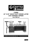
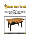
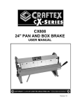
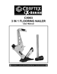
CX810 50" SLIP ROLL, 16 GAUGE USER MANUAL Version 1.0 TABLE OF CONTENTS Safety Instructions -------------------------------------------------------------------- 3 Features --------------------------------------------------------------------------------- 4 Physical Features --------------------------------------------------------------------- 5 Un-packing------------------------------------------------------------------------------ 6 Setup ------------------------------------------------------------------------------------- 6 Inventory -------------------------------------------------------------------------------- 6 Assembly-------------------------------------------------------------------------------- 6 Mounting -------------------------------------------------------------------------------- 6 Basic Controls ------------------------------------------------------------------------- 7 Preparations---------------------------------------------------------------------------- 8 Flat Rolling`----------------------------------------------------------------------------- 8 Creating Bends ------------------------------------------------------------------------ 9 Bending Wires ------------------------------------------------------------------------- 9 Removing Work-piece --------------------------------------------------------------- 10 Maintenance---------------------------------------------------------------------------- 10 Lubrication ------------------------------------------------------------------------------ 10 CX810 Parts Diagram---------------------------------------------------------------- 11 CX810 Parts List ---------------------------------------------------------------------- 12 Warranty--------------------------------------------------------------------------------- 13 2 SAFETY INSTRUCTIONS Extreme caution should be used when operating machines. Know your tool, be familiar with its operation, read through the owner’s manual and practice safe usage procedures at all times. Always read and understand the user manual before operating the machine. Always chamfer sharp metal edges before inserting them into the slip roll. Sharp edges of the sheet metal can cause severe cuts. Always wear leather gloves for the protection of your hands, when using the slip roll. Keep your fingers out of the roller path when operating the slip roll. Do not wear loose clothing or jewelry when operating the slip roll. A safe environment is important. Keep the area free of dust, dirt and other debris in the immediate vicinity of your machine. Do not use prescription or other drugs that may affect your ability or judgment to safely use your machine. Make sure that the rollers and workpiece are supported properly when operating. Always wear steel toe safety shoes to protect your feet if you drop a roller or work-piece. Do not force the machine to do a job for which it is not designed. Do not overreach. Maintain stability and balance at all times. Always check the machine for any damaged parts and service or replace them before operation. Keep children and visitors away at a safe distance from the machine while operation. Always make sure that any tools used for adjustments are removed before operating the machine. Maintain and service your machine regularly as instructed in the manual. 3 CX810 - 50" SLIP ROLL FEATURES MODEL CX810 - 50" SLIP ROLL As part of the growing line of Craftex CX-Series, we are proud to offer the CX810 a 50” Slip Roll. By following the instructions and procedures laid out in this user manual, you will receive years of excellent service and satisfaction. The CX810 is a professional tool and like all power tools, proper care and safety procedures should be adhered to. Maximum Capacity .......................................50" Roll Capacity .................................................3" Gauge ...........................................................16 Gauge (Mild Steel) Rod/Wire Grooves Diameter .........................5/16", 3/8" & 1/2" Hardened Steel Gearing ...............................Yes Weight...........................................................195 lbs Warranty .......................................................3 Years Country of Origin...........................................Taiwan 4 CX810 - 50" SLIP ROLL PHYSICAL FEATURES Upper Roller Gear Cover Bushing Bolt with Lock Nut Thickness Adjustment Knob Rear Roller Upper Roller Blade Guard Lock Knob Crank Radius Adjustment Knob 5 UNPACKING ASSEMBLY The slip roll is properly packaged in a crate for safe transportation. When unpacking, carefully inspect the crate and ensure that nothing has been damaged during transit. The CX810 comes fully assembled from the factory and all you need is to install the crank and the handle. To assemble your machine: Thread the crank handle into the crank as shown in figure-1. SETUP The unpainted surface of the slip roll is coated with a rust preventive waxy oil and you will want to remove this before you begin assembly. Use a solvent cleaner that will not damage painted surfaces. When setting up your machine, you will want to find an ideal spot where your slip roll will most likely be positioned most of the time. Consider your complete work environment before placing your machine in the ideal spot. INVENTORY Slide the crank with the handle onto the shaft and secure it by tightening the set screw. See figure-2. The CX810 comes with the following: CONTENTS A. B. C. D. Figure-1 Installing the crank handle QTY Slip Roll ............................................. 1 Crank Handle ................................... 1 Crank................................................. 1 Set Screw.......................................... 1 While doing the inventory if you can not find any parts, check if the part is already installed on the machine. Figure-2 Installing the crank onto the shaft MOUNTING The CX810 features four pre-drilled holes on its base which allow mounting the slip roll to the workbench. 6 There are two ways to mount the slip roll onto the workbench; through mount and direct mount. "Through Mount" is the strongest mounting option where the holes are drilled all the way through the workbench. Hex bolts, washers and hex nuts are used to secure the slip roll to the workbench. See figure-3. BASIC CONTROLS Read the descriptions below and get familiar with the basic controls on your CX810 slip roll. Figure-5 Basic controls Figure-3 Through mount Removable Bushing It slides out allowing the removal of the upper roller to help in the uploading of the cylindrical work-pieces. "Direct Mount" is to simply secure the slip roll to the workbench using lag screws. See figure-4. Thickness Adjustment Knob It raises or lowers the lower roller to adjust for the thickness of the work-piece. Radius Adjustment Knob It raises and lowers the rear roller creating smaller or larger radium bends. Crank It turns the rollers, feeding the work-piece into the machine. Figure-4 Direct mount 7 PREPARATION FLAT ROLLING Before every use follow the following procedures to set up your slip for safe and accurate efficient. Flat rolling is done to flatten or slightly reduce the thickness of the work-piece. The CX810 has a flat rolling capacity of up to 16 gauge. To prepare the slip roll: To flat roll a work-piece: Lower the lower roller to approximately 1/4" below the upper roller by using the thickness adjustment knob. Adjust the rollers using calipers or spacers so that the distance between rollers are even at each end. Lower the rear roller until it is even with the lower roller. Adjust the distance between rear roller and upper roller using spacers and calipers and make sure it is even on both ends. Check the upper roller bushing bolt and make sure it is threaded into the upper roller bushing properly and the lock nut is tightened. See figure-6. Insert the work-piece between the upper and lower rollers and turn the thickness adjustment knobs on both ends to an equal amount until the work-piece is held between the rollers. Now, remove the work-piece and adjust the thickness adjustment knobs approximately 1/4 turn to slightly raise the lower roller. Make sure the rear roller is lowered completely so that it does not interfere with the work-piece when it comes out of the machine. Feed the work-piece into the machine while turning the crank. Continue the procedures above until you get the desired results. WARNING! Keep your fingers, hair and loose clothing away from the rollers on the CX810. Failure to do so could result in hair, fingers or clothing pulled into the machine and cause serious personal injury. Figure-6 Upper roller bushing bolt and lock nut 8 CREATING BENDS BENDING WIRES The CX810 creates radius bends in sheet metal up to 16 gauge. The CX810 can also bend wires, rods and small diameter tubing. To create a bend: To bend wires, rods or tubing: Insert the work-piece between the upper and lower rollers and turn the thickness adjustment knobs on both ends to an equal amount until the work-piece is held between the rollers. Place your work-piece into the smallest possible groove that it will fit in, on the wheel shown in figure-7. Feed the work-piece into the slip roll by turning the crank clockwise until the edge of the work-piece is directly above the read roller. Lift the rear roller by turning the radius adjustment knobs at an equal amount until the desired radius bend is reached. Make sure the radius adjustment knobs are turned at an equal amount or it will create larger radius on one end than the other. Turn the crank to feed the material through the rollers until the work-piece is completely through the rollers. Figure-7 Wire grooves Feed the work-piece into the slip roll by turning the crank clockwise until the edge of the work-piece is directly above the read roller. Lift the rear roller by turning the radius adjustment knobs at an equal amount until the desired radius bend is reached. Make sure the radius adjustment knobs are turned at an equal amount or it will create larger radius on one end than the other. Turn the crank to feed the material through the rollers until the work-piece is completely through the rollers. 9 REMOVING WORK-PIECE MAINTENANCE To remove the cylindrical work-piece: During the life of you machine, you will need to practice some regular maintenance to keep your slip roll in peak performance condition. Loosen the upper roller bushing bolt and lock nut securing the upper roller at the gearbox. See figure-8. Check the sip roll daily for any loose mounting bolts or any other unsafe condition. Wipe down the dust and oil on your slip roll and use a non-staining lubricant to clean the un painted surfaces. LUBRICATION Figure-8 Removing the bolt and lock nut Slide the bushing outward and release the upper roller but do not remove the roller yet. Get the help of an assistant, slide and lift the upper roller out. Remove the work-piece from the upper roller and place the upper roller onto the base. Move the upper roller back into position and slide the removable bushing in, securing the upper roller. To lubricate the slip roll you will just need to apply some lubricant to the gears, adjustment screws and roller bushings. To lubricate the gears: Remove the gears cover by removing the screws securing it to the slip roll. Apply a light coat of grease to the gear teeth and turn the crank handle to disperse the grease. Also apply some grease to the adjustment screws. See figure-9. Thread the hex bolt back into the roller bushing and tighten the lock nut against the base to lock the hex bolt in position. Figure-9 Lubricating the gears and the adjustment screws 10 11 12 WARRANTY CRAFTEX 3 YEARS LIMITED WARRANTY Craftex warrants every product to be free from defects in materials and agrees to correct such defects where applicable. This warranty covers three years for parts and 90 days for labour (unless specified otherwise), to the original purchaser from the date of purchase but does not apply to malfunctions arising directly or indirectly from misuse, abuse, improper installation or assembly, negligence, accidents, repairs or alterations or lack of maintenance. Proof of purchase is necessary. All warranty claims are subject to inspection of such products or part thereof and Craftex reserves the right to inspect any returned item before a refund or replacement may be issued. This warranty shall not apply to consumable products such as blades, bits, belts, cutters, chisels, punches etceteras. Craftex shall in no event be liable for injuries, accidental or otherwise, death to persons or damage to property or for incidental contingent, special or consequential damages arising from the use of our products. RETURNS, REPAIRS AND REPLACEMENTS To return, repair, or replace a Craftex product, you must visit the appropriate Busy Bee Tools showroom or call 1800-461-BUSY. Craftex is a brand of equipment that is exclusive to Busy Bee Tools. For replacement parts directly from Busy Bee Tools, for this machine, please call 1-800-461-BUSY (2879), and have your credit card and part number handy. All returned merchandise will be subject to a minimum charge of 15% for re-stocking and handling with the following qualifications. Returns must be pre-authorized by us in writing. We do not accept collect shipments. Items returned for warranty purposes must be insured and shipped pre-paid to the nearest warehouse Returns must be accompanied with a copy of your original invoice as proof of purchase. Returns must be in an un-used condition and shipped in their original packaging a letter explaining your reason for the return. Incurred shipping and handling charges are not refundable. Busy Bee will repair or replace the item at our discretion and subject to our inspection. Repaired or replaced items will be returned to you pre-paid by our choice of carriers. Busy Bee reserves the right to refuse reimbursement or repairs or replacement if a third party without our prior authorization has carried out repairs to the item. Repairs made by Busy Bee are warranted for 30 days on parts and labour. Any unforeseen repair charges will be reported to you for acceptance prior to making the repairs. The Busy Bee Parts & Service Departments are fully equipped to do repairs on all products purchased from us with the exception of some products that require the return to their authorized repair depots. A Busy Bee representative will provide you with the necessary information to have this done. For faster service it is advisable to contact the nearest Busy Bee location for parts availability prior to bringing your product in for repairs. 13