1
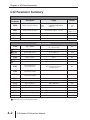
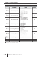
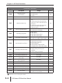
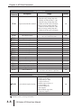
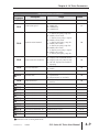
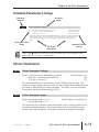
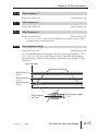
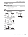
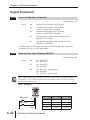
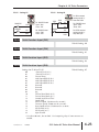
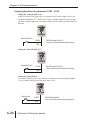
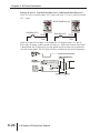
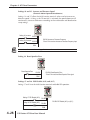
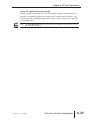
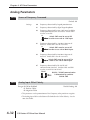
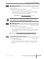
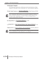
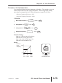
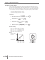
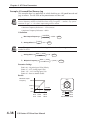
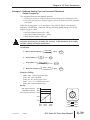
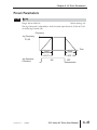
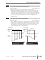
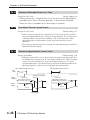
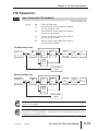
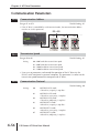
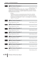
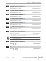
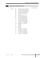
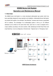
AC DRIVE
PARAMETERS
CHAPTER
4
In This Chapter...
GS2 Parameter Summary . . . . . . . . . . . . . . . . . . . .4–2
Detailed Parameter Listings . . . . . . . . . . . . . . . . .4–11
Motor Parameters . . . . . . . . . . . . . . . . . . . . . . . .4–11
Ramp Parameters . . . . . . . . . . . . . . . . . . . . . . . . .4–13
Volts/Hertz Parameters . . . . . . . . . . . . . . . . . . . . .4–19
Digital Parameters . . . . . . . . . . . . . . . . . . . . . . . .4–22
Setting Explanations for parameters P3.02 - P3.05 . . . . . . . . . .4–24
Analog Parameters . . . . . . . . . . . . . . . . . . . . . . . .4–32
Analog Input Examples . . . . . . . . . . . . . . . . . . . . . . . . . . . . . . .4–34
Preset Parameters . . . . . . . . . . . . . . . . . . . . . . . .4–41
Protection Parameters . . . . . . . . . . . . . . . . . . . . .4–43
PID Parameters . . . . . . . . . . . . . . . . . . . . . . . . . .4–51
Display Parameters . . . . . . . . . . . . . . . . . . . . . . . .4–55
Communication Parameters . . . . . . . . . . . . . . . . .4–56
Chapter 4: AC Drive Parameters
GS2 Parameter Summary
Motor Parameters
GS2
Parameter
Description
P0.00
Motor Nameplate Voltage
P0.01
Motor Nameplate Amps
Drive Rated Amps X .3 to 1.0
Drive Rated
Amps x 1.0
P0.02
P0.03
P0.04
Motor Base Frequency
50/60/400
60
Motor Base RPM
375 to 9999 RPM
1750
Motor Maximum RPM
P0.03 to 9999 RPM
P0.03
Range
115V/230V: 200/208/220/230/240
460V:
380/400/415/440/460/480
575V:
380 to 637
Default
240
480
575
Ramp Parameters
P1.00
P1.01
P1.02
P1.03
P1.04
P1.05
P1.06
P1.07
P1.08
P1.09
P1.10
P1.11
P1.12
P1.17
P1.18
P1.20
P1.21
P1.22
Stop Methods
00: Ramp to Stop
01: Coast to Stop
00
Acceleration Time 1
0.1 to 600.0 sec
10.0
Deceleration Time 1
0.1 to 600.0 sec
30.0
Accel S-curve
0 to 7
00
Decel S-curve
0 to 7
00
Acceleration Time 2
0.1 to 600.0 sec
10.0
Deceleration Time 2
0.1 to 600.0 sec
30.0
Select method to use
2nd Accel/Decel
00: RMP2 from DI terminal
01: Transition Frequencies
P1.08 & P1.09
00
0.0 to 400.0 Hz
0.0
0.0 to 400.0 Hz
0.0
Skip Frequency 1
0.0 to 400.0 Hz
0.0
Skip Frequency 2
0.0 to 400.0 Hz
0.0
Skip Frequency 3
0.0 to 400.0 Hz
0.0
Skip Frequency Band
0.0 to 20.0 Hz
0.0
DC Injection Current Level
00 to 100 %
00
DC Injection during Start-up
0.0 to 5.0 sec
0.0
DC Injection during Stopping
0.0 to 25.0 sec
0.0
Start-point for DC Injection
0.0 to 60.0 Hz
0.0
Accel 1 to Accel 2
frequency transition
Decel 2 to Decel 1
frequency transition
Parameter can be set during RUN Mode.
4–2
GS2 Series AC Drive User Manual
Chapter 4: AC Drive Parameters
Volts/Hertz Parameters
GS2
Parameter
Description
Range
Default
00: General Purpose
01: High Starting Torque
02: Fans and Pumps
03: Custom
P2.00
Volts/Hertz Settings
P2.01
P2.02
P2.04
Slip Compensation
0.0 to 10.0
0.0
Auto-torque Boost
00 to 10
00
Mid-point Frequency
0.1 to 400 Hz
1.5
115V/230V:
460V:
575V:
P2.05
Mid-point Voltage
P2.06
Min. Output Frequency
P2.07
Min. Output Voltage
P2.08
PWM Carrier Frequency
00
2.0 to 255V
2.0 to 510V
2.0 to 637V
0.1 to 20.0 Hz
10.0
20.0
24.0
1.50
115V/230V:
460V:
575V:
2.0 to 50.0V
2.0 to 100.0V
2.0 to 130.6V
10.0
20.0
24.0
115V/230V/460V
575V
01 to 15 kHz
01 to 10 kHz
12
6
Digital Parameters
P3.00
P3.01
00: Operation determined by digital keypad
01: Operation determined by external control
terminals, keypad STOP is enabled
02: Operation determined by external control
Source of Operation Command
terminals, keypad STOP is disabled
03: Operation determined by RS-485 interface,
keypad STOP is enabled
04: Operation determined by RS-485
interface, keypad STOP is disabled
00: DI1 - FWD / STOP, DI2 - REV / STOP
01: DI1 - RUN / STOP, DI2- REV / FWD
Multi-function Input Terminals
02: DI1 - RUN momentary (N.O.)
(DI1 - DI2)
DI2 - REV / FWD
DI3 - STOP momentary (N.C.)
00
00
Parameter can be set during RUN Mode.
1st Ed. Rev. C
12/2006
GS2 Series AC Drive User Manual
4–3
Chapter 4: AC Drive Parameters
Digital Parameters (cont.)
GS2
Parameter
Description
P3.02
Multi-function Input (DI3)
P3.03
Multi-function Input (DI4)
P3.04
Multi-function Input (DI5)
P3.05
Multi-function Input (DI6)
P3.11
P3.12
P3.16
P3.17
P3.18
P3.19
Range
00: External Fault (N.O.)
01: External Fault (N.C.)
02: External Reset
03: Multi-Speed/PID SP Bit 1
04: Multi-Speed/PID SP Bit 2
05: Multi-Speed/PID SP Bit 3
06: Reserved
07: Reserved
08: Reserved
09: Jog
10: External Base Block (N.O.)
11: External Base Block (N.C.)
12: Second Accel/Decel Time
13: Speed Hold
14: Increase Speed
15: Decrease Speed
16: Reset Speed to Zero
17: PID Disable (N.O.)
18: PID Disable (N.C.)
99: Input Disable
00: AC Drive Running
01: AC Drive Fault
Multi-Function Output Terminal 02: At Speed
1
03: Zero Speed
04: Above Desired Frequency
05: Below Desired Frequency
06: At Maximum Speed
Multi-Function Output Terminal 07: Over torque detected
08: Above Desired Current
2
09: Below Desired Current
10: PID Deviation Alarm
Desired Frequency
00
03
04
05
00
01
0.0 to 400.0 Hz
0.0
0.0 to <Drive Rated Amps>
0.0
PID Deviation Level
1.0 to 50.0 %
10.0
PID Deviation Time
0.1 to 300.0 sec
5.0
Desired Current
Parameter can be set during RUN Mode.
4–4
Default
GS2 Series AC Drive User Manual
Chapter 4: AC Drive Parameters
Analog Parameters
GS2
Parameter
P4.00
P4.01
P4.02
P4.03
P4.04
P4.05
Description
Range
Default
00: Frequency determined by keypad
potentiometer
01: Frequency determined by digital keypad
up/down
02: Frequency determined by 0 to +10V
input on AI terminal with jumpers
Source of Frequency Command
03: Frequency determined by 4 to 20mA
input on AI terminal with jumpers
04: Frequency determined by 0 to 20mA
input on AI terminal with jumpers
05: Frequency determined by RS-232C/
RS-485 communication interface
00: No Offset
Analog Input Offset Polarity
01: Positive Offset
02: Negative Offset
00
00
Analog Input Offset
0.0 to 100.0%
0.0
Analog Input Gain
0.0 to 300.0%
100.0
Analog Input Reverse Motion
Enable
Loss of ACI Signal
(4-20mA)
00: Forward Motion Only
01: Reverse Motion Enable
00
00: Decelerate to 0Hz
01: Stop immediately and display error
code “EF”
02: Continue operation by the last
frequency command
00
P4.11
Analog Output Signal
00: frequency Hz
01: Current A
02: PV
00
P4.12
Analog Output Gain
00 to 200%
100
Presets
P5.00
P5.01
P5.02
P5.03
P5.04
P5.05
P5.06
P5.07
Jog
0.0 to 400.0 Hz
6.0
Multi-Speed 1
0.0 to 400.0 Hz
0.0
Multi-Speed 2
0.0 to 400.0 Hz
0.0
Multi-Speed 3
0.0 to 400.0 Hz
0.0
Multi-Speed 4
0.0 to 400.0 Hz
0.0
Multi-Speed 5
0.0 to 400.0 Hz
0.0
Multi-Speed 6
0.0 to 400.0 Hz
0.0
Multi-Speed 7
0.0 to 400.0 Hz
0.0
Parameter can be set during RUN Mode.
1st Ed. Rev. C
12/2006
GS2 Series AC Drive User Manual
4–5
Chapter 4: AC Drive Parameters
Protection Parameters
GS2
Parameter
Description
P6.00
Electronic Thermal
Overload Relay
P6.01
Auto Restart after Fault
P6.02
Momentary Power Loss
P6.03
Reverse Operation Inhibit
Range
00: Constant Torque
01: Variable Torque
02: Inactive
00
00 to 10
00
00: Stop operation after momentary power
loss
01: Continue operation after momentary
power loss, speed search from Speed
Reference
02: Continue operation after momentary
power loss, speed search from
Minimum Speed
00: Enable Reverse Operation
01: Disable Reverse Operation
00
00
00: AVR enabled
01: AVR disabled
02: AVR disabled during decel
03: AVR disabled during stop
00
P6.04
Auto Voltage Regulation
P6.05
Over-Voltage Stall Prevention
00: Enable Over-voltage Stall Prevention
01: Disable Over-voltage Stall Prevention
00
Auto Adjustable Accel/Decel
00: Linear Accel/Decel
01: Auto Accel, Linear Decel
02: Linear Accel, Auto Decel
03: Auto Accel/Decel
04: Auto Accel/Decel Stall Prevention
(limited by P1.01, P1.02, P1.05, P1.06)
00
P6.07
Over-Torque Detection Mode
00: Disabled
01: Enabled during constant speed
operation
02: Enabled during acceleration
00
P6.08
P6.09
Over-Torque Detection Level
30 to 200%
150
Over-Torque Detection Time
0.1 to 10.0
0.1
20 to 200%
150
20 to 200%
150
Maximum Allowable Power Loss Time
0.3 to 5.0 sec
2.0
P6.06
P6.10
P6.11
Over-Current Stall Prevention during
Acceleration
Over-Current Stall Prevention
during Operation
P6.12
P6.13
P6.14
P6.15
P6.16
Base-Block Time for Speed Search
0.3 to 5.0 sec
0.5
Maximum Speed Search Current Level
30 to 200%
150
Upper Bound of Output Frequency
0.1 to 400Hz
400
Lower Bound of Output Frequency
0.0 to 400Hz
0.0
P6.30
Line Start Lockout
00: Enable Line Start Lockout
01: Disable Line Start Lockout
Parameter can be set during RUN Mode.
4–6
Default
GS2 Series AC Drive User Manual
00
Chapter 4: AC Drive Parameters
Protection Parameters (cont.)
GS2
Parameter
P6.31
P6.32
P6.33
P6.34
P6.35
P6.36
Description
Range
Default
00: No Fault occurred
01: Over-current (oc)
Present Fault Record
02: Over-voltage (ov)
03: Overheat (oH)
04: Overload (oL)
Second Most Recent Fault Record 05: Overload 1 (oL1)
06: Overload 2 (oL2)
07: External Fault (EF)
Third Most Recent Fault Record 08: CPU failure 1 (CF1)
09: CPU failure 2 (CF2)
10: CPU failure 3 (CF3)
11: Hardware Protection Failure (HPF)
Fourth Most Recent Fault Record 12: Over-current during accel (OCA)
13: Over-current during decel (OCd)
14: Over-current during steady state (OCn)
15:Ground fault or fuse failure (GFF)
Fifth Most Recent Fault Record
16: Reserved
17: Input power 3-phase loss
18: External Base-Block (bb)
Sixth Most Recent Fault Record
19: Auto Adjust accel/decel failure (cFA)
20: Software protection code (codE)
00
00
00
00
00
00
Parameter can be set during RUN Mode.
1st Ed. Rev. C
12/2006
GS2 Series AC Drive User Manual
4–7
Chapter 4: AC Drive Parameters
PID Parameters
GS2
Parameter
P7.00
Description
Range
00: Inhibit PID operation
01: Forward-acting (heating loop) PID
feedback, PV from AVI (0 to + 10V
02: Forward-acting (heating loop) PID
Input Terminal for PID Feedback
feedback, PV from ACI (4 to 20mA)
03: Reverse-acting (cooling loop) PID
feedback, PV from AVI (0 to +10V).
04: Reverse-acting (cooling loop) PID
feedback, PV from ACI (4 to 20mA).
P7.01
PV 100% Value
P7.02
PID Setpoint Source
P7.10
P7.11
P7.12
P7.13
P7.14
P7.15
P7.16
P7.17
P7.20
P7.21
P7.22
P7.23
P7.24
P7.25
P7.26
P7.27
Default
00
0.0 to 999
00: Keypad
01: Serial Communications
100.0
Keypad PID Setpoint
0.0 to 999
0.0
PID Multi-setpoint 1
0.0 to 999
0.0
PID Multi-setpoint 2
0.0 to 999
0.0
PID Multi-setpoint 3
0.0 to 999
0.0
PID Multi-setpoint 4
0.0 to 999
0.0
PID Multi-setpoint 5
0.0 to 999
0.0
PID Multi-setpoint 6
0.0 to 999
0.0
PID Multi-setpoint 7
0.0 to 999
0.0
00
Proportional Control
0.0 to 10.0
1.0
Integral Control
0.00 to 100.0 sec
1.00
Derivative Control
0.00 to 1.00 sec
0.00
Upper Bound for Integral Control
00 to 100%
100
Derivative Filter Time Constant
0.0 to 2.5 sec
0.0
PID Output Frequency Limit
00 to 110%
100
Feedback Signal Detection Time
0.0 to 3600 sec.
00: Warn and AC Drive Stop
01: Warn and Continue Operation
60
PID Feedback Loss
00
Display Parameters
P8.00
User Defined Display Function
P8.01
Frequency Scale Factor
00: Output Frequency (Hz)
01: Motor Speed (RPM)
02: Output Freq. X P8.01
03: Output Current (A)
04: Motor Output Current (%)
05: Output Voltage (V)
06: DC Bus Voltage (V)
07: PID Setpoint
08: PID Feedback Signal (PV)
09: Frequency Setpoint
00
0.01 to 160.0
1.0
Parameter can be set during RUN Mode.
4–8
GS2 Series AC Drive User Manual
Chapter 4: AC Drive Parameters
Communications Parameters
GS2
Description
Parameter
Communication Address
P9.00
P9.01
P9.02
01
Transmission Speed
00:
01:
02:
03:
01
Communication Protocol
00: Modbus ASCII mode
7 data bits,no parity,2 stop bits
01: Modbus ASCII mode
7 data bits,even parity,1 stop bit
02: Modbus ASCII mode
7 data bits,odd parity,1 stop bit
03: Modbus RTU mode
8 data bits,no parity,2 stop bits
04: Modbus RTU mode
8 data bits,even parity,1 stop bit
05: Modbus RTU mode
8 data bits,odd parity,1 stop bit
Transmission Fault Treatment
P9.04
Time Out Detection
P9.05
Time Out Duration
P9.08
P9.11
P9.12
P9.13
P9.14
P9.15
P9.16
P9.17
P9.18
P9.19
P9.20
P9.21
P9.22
Default
01 to 254
P9.03
P9.07
Range
Parameter Lock
Restore to Default
4800 baud
9600 baud
19200 baud
38400 baud
00:
01:
02:
03:
Display fault and continue operating
Display fault and RAMP to stop
Display fault and COAST to stop
No fault displayed and continue
operating
00: Disable
01: Enable
0.1 to 60.0 seconds
00: All parameters can be
set and read
01: All parameters are read-only
99: Restores all parameters to factory
defaults
00
00
00
0.5
00
00
Block Transfer Parameter 1
P0.00 to P8.01, P9.99
P9.99
Block Transfer Parameter 2
P0.00 to P8.01, P9.99
P9.99
Block Transfer Parameter 3
P0.00 to P8.01, P9.99
P9.99
Block Transfer Parameter 4
P0.00 to P8.01, P9.99
P9.99
Block Transfer Parameter 5
P0.00 to P8.01, P9.99
P9.99
Block Transfer Parameter 6
P0.00 to P8.01, P9.99
P9.99
Block Transfer Parameter 7
P0.00 to P8.01, P9.99
P9.99
Block Transfer Parameter 8
P0.00 to P8.01, P9.99
P9.99
Block Transfer Parameter 9
P0.00 to P8.01, P9.99
P9.99
Block Transfer Parameter 10
P0.00 to P8.01, P9.99
P9.99
Block Transfer Parameter 11
P0.00 to P8.01, P9.99
P9.99
Block Transfer Parameter 12
P0.00 to P8.01, P9.99
P9.99
Parameter can be set during RUN Mode.
1st Ed. Rev. C
12/2006
GS2 Series AC Drive User Manual
4–9
Chapter 4: AC Drive Parameters
Communications Parameters (continued)
GS2
Parameter
P9.23
P9.24
P9.25
P9.26
Description
Range
Default
Block Transfer Parameter 13
P0.00 to P8.01
P9.99
Block Transfer Parameter 14
P0.00 to P8.01
P9.99
Block Transfer Parameter 15
P0.00 to P8.01
P9.99
Serial Comm Speed Reference
0.0 to 400.0 Hz
60.0
P9.27
Serial Comm RUN Command
P9.28
Serial Comm Direction Command
P9.29
Serial Comm External Fault
P9.30
Serial Comm Fault Reset
P9.31
Serial Comm JOG Command
00: Stop
01: Run
00: Forward
01: Reverse
00: No fault
01: External fault
00: No action
01: Fault Reset
00: Stop
01: Jog
00
00
00
00
00
P9.39
Firmware Version
#.##
P9.41
GS Series Number
01: GS1
02: GS2
03: GS3
##
Manufacturer Model Information
00: GS2-20P5 (230V 1ph/3ph 0.5hp)
01: GS2-21P0 (230V 1ph/3ph 1hp)
02: GS2-22P0 (230V 1ph/3ph 2hp)
03: GS2-23P0 (230V 1ph/3ph 3hp)
04: GS2-25P0 (230V 3ph 5hp)
05: GS2-27P5 (230V 3ph 7.5hp)
06: Reserved
07: GS2-41P0 (460V 3ph 1hp)
08: GS2-42P0 (460V 3ph 2hp)
09: GS2-43P0 (460V 3ph 3hp)
10: GS2-45P0 (460V 3ph 5hp)
11: GS2-47P5 (460V 3ph 7.5hp)
12: GS2-4010 (460V 3ph 10hp)
13: GS2-10P2 (115V 1ph 0.25hp)
14: GS2-10P5 (115V 1ph 0.5hp)
15: GS2-11P0 (115V 1ph 1hp)
16~20: Reserved
21: GS2-51P0 (575V 3ph 1hp)
22: GS2-52P0 (575V 3ph 2hp)
23: GS2-53P0 (575V 3ph 3hp)
24: GS2-55P0 (575V 3ph 5hp)
25: GS2-57P5 (575V 3ph 7.5hp)
26: GS2-5010 (575V 3ph 10hp)
##
P9.42
Parameter can be set during RUN Mode.
4–10
GS2 Series AC Drive User Manual
#.##
Chapter 4: AC Drive Parameters
Detailed Parameter Listings
Parameter
Name
Parameter
Number
P0.00
Motor Nameplate Voltage
Range: 115V/230V classes: 200/208/220/230/240
460V class: 380/400/415/440/460/480
575V class: 380 to 637
Default Setting: 240
Default Setting: 480
Default Setting: 575
•This parameter determines the Maximum Output Voltage of the AC drive. The Maximum Output
Voltage setting must be less than or equal to the rated voltage of the motor as indicated on the
motor nameplate. The setting value must be equal to or greater than the Mid-Point Voltage
(P2.05).
Parameter Setting
Range
Parameter
Description
Parameter Default
Setting
Note: If the symbol is found next to the parameter name, the parameter can be
edited when the AC drive is in RUN Mode.
Motor Parameters
P0.00
Motor Nameplate Voltage
Range: 115V/230V classes: 200/208/220/230/240
460V class: 380/400/415/440/460/480
575V class: 380 to 637
Default Setting: 240
480
575
This parameter determines the Maximum Output Voltage of the AC drive. The
Maximum Output Voltage setting must be less than or equal to the rated voltage of
the motor as indicated on the motor nameplate. The setting value must be equal
to or greater than the Mid-Point Voltage (P2.05).
P0.01
Motor Nameplate Amps
Range: Drive Rated Amps x 0.3 to
Drive Rated Amps x 1.0
Default Setting: Drive Rating (A)
This parameter sets the output current to the motor, and is used by the drive to set
the motor overload protection. Set this parameter value to the full load current
listed on the motor nameplate. (Also refer to P6.00 to set overload curve type.)
1st Ed. Rev. C
12/2006
GS2 Series AC Drive User Manual
4–11
Chapter 4: AC Drive Parameters
P0.02
Motor Base Frequency
Range: 50/60/400
Default Setting 60
•This value should be set according to base frequency of the motor as indicated on
the motor nameplate. Motor Base Frequency determines the volts per hertz ratio.
P0.03
Motor Base RPM
Range: 375 to 9999 RPM
Default Setting: 1750
• This value should be set according to rated Base RPM of the motor as indicated on
the motor nameplate.
P0.04
Motor Maximum RPM
Range: P0.03 to 9999 RPM
Default Setting: P0.03
• This value should be set according to the desired maximum speed of the motor.
This value should not exceed the motor’s maximum rated speed.
WARNING: The Motor Maximum RPM parameter (P0.04) should never exceed the
maximum speed rating for the motor you are using. If this information is not readily
available, consult your motor manufacturer.
• This value cannot be set lower than Motor Base RPM (P0.03).
This parameter, along with P0.02 and P0.03, determines the Maximum Output
Frequency of the AC Drive. The Maximum Output Frequency can be calculated
as follows:
Max. Output Frequency =
Motor Max. RPM (P0-04)
x Base Frequency (P0-02)
( Motor
Base RPM (P0-03) )
• If an output limit based on Maximum Output Frequency is desired, use the following
equation to determine the corresponding value for Motor Maximum RPM:
Motor Maximum RPM =
4–12
( Motor Base Frequency (P 0.02) ) x Motor Base RPM (P 0.03)
Max. Output Frequency
GS2 Series AC Drive User Manual
Chapter 4: AC Drive Parameters
Ramp Parameters
Stop Methods
P1.00
Range: 00 Ramp to Stop
01 Coast to stop
Default Setting: 00
This parameter determines how the motor is stopped when the AC drive receives a
valid stop command.
• Ramp: The AC drive decelerates the motor to Minimum Output Frequency (P2.06)
and then stops according to the deceleration time set in P1.02 or P1.06.
•Coast:The AC drive stops output instantly upon command, and the motor free runs
until it comes to a complete stop.
Note: The drive application or system requirements will determine which stop method is
needed.
Hz
Hz
Frequency
Frequency
Stops according to
deceleration time
Free running to stop
Motor
Speed
Motor
Speed
time
Operation
Command
?
decel
time
ON
OFF
Ramp
P1.01
time
ON
OFF
Coast
Acceleration Time 1
Range: 0.1 to 600 sec
Default Setting: 10 sec
This parameter is used to determine the time required for the AC drive to ramp
from 0 to its Maximum Motor RPM (P0.04). The rate is linear unless S-Curve is
"Enabled."
1st Ed. Rev. C
12/2006
GS2 Series AC Drive User Manual
4–13
Chapter 4: AC Drive Parameters
P1.02
Deceleration Time 1
Range: 0.1 to 600 sec
Default Setting: 30 sec
This parameter is used to determine the time required for the AC drive to
decelerate from the Maximum Motor RPM (P0.04) down to 0Hz. The rate is
linear unless S-Curve is “Enabled.”
P1.03
Accel S-Curve
Range: 00 to 07
Default Setting: 00
This parameter is used whenever the motor and load need to be accelerated more
smoothly. The Accel S-Curve may be set from 0 to 7 to select the desired
acceleration S Curve.
Frequency
Time
S-curve
characteristics
Time
S-curve
characteristics
Time
P 1.04 = 00
"Decel S curve Disabled"
P 1.03 = 00
"Accel S curve Disabled"
Time
Accel Time
1 or 2
4–14
GS2 Series AC Drive User Manual
Decel Time
1 or 2
Chapter 4: AC Drive Parameters
P1.04
Decel S-Curve
Range: 00 to 07
Default Setting: 00
This parameter is used whenever the motor and load need to be decelerated more
smoothly. The Decel S-Curve may be set from 00 to 07 to select the desired
deceleration S-Curve.
Note: From the diagram shown below, the original setting accel/decel time will be
for reference when the function of the S-curve is enabled. The actual accel/decel
time will be determined based on the S-curve selected (1 to 7).
Frequency
P 1.04
P 1.03
(1)
(2)
(4)
(3)
Time
(1)
(2)
(3)
(4)
S curve is disabled in (1), (2)
P 1.03 sets S curve for (3)
P 1.04 sets S curve for (4)
P1.05
Acceleration Time 2
Range: 0.1 to 600 sec
Default Setting: 10.0
•The Second Acceleration Time determines the time for the AC drive to accelerate
from 0 RPM to Maximum Motor RPM (P0.04). Acceleration Time 2 (P1.05) can be
selected using a multi-function input terminal or frequency transition (P1.07).
P1.06
Deceleration Time 2
Range: 0.1 to 600 sec
Default Setting: 30 sec
•The Second Deceleration Time determines the time for the AC drive to decelerate
from Maximum Motor RPM (P0.04) to 0 RPM. Deceleration Time 2 (P1.06) can be
selected using a multi-function input terminal or frequency transition (P1.07).
1st Ed. Rev. C
12/2006
GS2 Series AC Drive User Manual
4–15
Chapter 4: AC Drive Parameters
P1.07
Select method for 2nd Accel/Decel
Range: 00: Second Accel/Decel from DI terminal
01: Frequency Transition
P1.08 & P1.09
Default Setting: 00
• The second set of acceleration and deceleration times P1.05 and P1.06 can be
selected either with a multi-function input terminal programmed to Second
Accel/Decel, or by the values of the transition frequencies P1.08 and P1.09
Second Accel/Decel Times selected with Multi-Function Input Terminal
Frequency
Maximum Output
Frequency P 0.04
Accel 1
P 1.01
Accel 2
P 1.05
Decel 2
P 1.06
Decel 1
P 1.02
Time
Multi-function
Input Terminal
P1.08
On
Off
Accel 1 to Accel 2 Frequency Transition
Range: 0.0 to 400.0 Hz
Default Setting: 0.0
Second Accel/Decel Times selected with Frequency Transition
Frequency
Maximum Output
Frequency P 0.04
Accel 1 to Accel 2
Frequency Transition
P 1.08
Accel 2
P 1.05
Accel 1
P 1.01
P1.09
Decel 1
P 1.02
Decel 2 to Decel 1
Frequency Transition
P 1.09
Time
Decel 1 to Decel 2 Frequency Transition
Range: 0.0 to 400.0 Hz
4–16
Decel 2
P 1.06
GS2 Series AC Drive User Manual
Default Setting: 0.0
Chapter 4: AC Drive Parameters
P1.10
Skip Frequency 1
Range: 0.0 to 400.0 Hz
P1.11
Skip Frequency 2
Range: 0.0 to 400.0 Hz
P1.12
Default Setting: 0.0
Default Setting: 0.0
Skip Frequency 3
Range: 0.0 to 400.0 Hz
Default Setting: 0.0
• P1.10, P1.11, and P1.12 determine the location of the frequency bands that will
be skipped during AC drive operation.
P1.17
Skip Frequency Band
Range: 0.0 to 20.0 Hz
Default Setting: 0.0
This parameter determines the frequency band for a given Skip Frequency (P1.10,
P1.11, or P1.12). Half of the Skip Frequency Band is above the Skip Frequency
and the other half is below. Programming this parameter to 0.0 disables all skip
frequencies.
Output frequency
Skip Frequency 3
P 1.12
Skip Frequency 2
P 1.11
Skip Frequency 1
P 1.10
Skip Frequency
Set Point
1st Ed. Rev. C
12/2006
Skip Frequency Band
P 1.17
GS2 Series AC Drive User Manual
4–17
Chapter 4: AC Drive Parameters
P1.18
DC Injection Current Level
Range: 00 to 100%
Default Setting: 00
This parameter determines the amount of DC Braking Current applied to the
motor during start-up and stopping. When setting DC Braking Current, please
note that 100% is equal to the rated current of the drive. It is recommended to
start with a low DC Braking Current Level and then increase until proper holding
torque has been attained.
P1.20
DC Injection during Start-up
Range: 0.0 to 5.0 sec
Default Setting: 0.0
This parameter determines the duration of time that the DC Braking Current will
be applied to the motor during the AC drive start-up. DC Braking will be applied
for the time set in this parameter until the Minimum Frequency is reached during
acceleration.
P1.21
DC Injection during Stopping
Range: 0.0 to 25.0 sec
Default Setting: 0.0
This parameter determines the duration of time that the DC braking voltage will
be applied to the motor during stopping. If stopping with DC Braking is desired,
then P1.00 must be set to Ramp to Stop (00).
P1.22
Start-point for DC Injection
Range: 0.0 to 60.0 Hz
Default Setting: 0.0
This parameter determines the frequency when DC Braking will begin during
deceleration.
Master
Frequency
Start-Point for DC Braking
Min. Output
Frequency
Operation
Command
P 1.22
P 1.21
P 1.20
ON
DC Injection Current Level
P 1.18
4–18
time
GS2 Series AC Drive User Manual
OFF
Chapter 4: AC Drive Parameters
Volts/Hertz Parameters
Volts/Hertz Settings
P2.00
Settings: 00
01
02
03
-
General Purpose (constant torque)
High Starting Torque
Fans and Pumps (variable torque)
Custom
Default Setting: 0.0
Note: P2.04 through P2.07 are only used when the Volts/Hertz parameter (P2.00) is set to 03.
00: General Purpose
Volts
03: Custom
Voltage
Volts
P0.00
P0.00
P0.00
P2.05
10/20
P2.07
10/20
60/400 Hz
1.5
1.5
60/400Hz Base Frequency
50.0 Hz
50Hz Base Frequency
Frequency
P2.06 P2.04 P0.02 P0.04
x P0.02
P0.03
01: High Starting Torque
Volts
Volts
P0.00
P0.00
23/46
23/46
18/36
14/28
1.5 3
60/400 Hz
1.3 2.2
60/400Hz Base Frequency
50.0 Hz
50Hz Base Frequency
02: Fans and Pumps
Volts
P0.00
Volts
P0.00
50/100
10/20
1.5 30
50/100
10/20
60/400 Hz
1.3 25
60/400Hz Base Frequency
1st Ed. Rev. C
12/2006
50.0 Hz
50Hz Base Frequency
GS2 Series AC Drive User Manual
4–19
Chapter 4: AC Drive Parameters
P2.01
Slip Compensation
Range: 0.0 to 10.0
Default Setting: 0.0
When controlling an asynchronous induction motor, load on the AC drive will
increase causing an increase in slip. This parameter may be used to compensate
the nominal slip within a range of 0 to 10. When the output current of the AC
drive is greater than the Motor Nameplate Amps (P0.01), the AC drive will adjust
its output frequency according to this parameter.
P2.02
Auto-torque Boost
Range: 00 to 10
Default Setting: 00
This parameter functions similarly to the P2.00-01 High Starting Torque V/Hz
setting, except that this parameter uses less current than does P2.00-01. P2.00-01
boosts starting torque by increasing current at every start beyond what is required
to move the load. P2.02 Auto-torque Boost increases the current only as required
to move the load. The proper setting for P2.02 is determined by trial and error.
P2.04 through P2.07 are used only when the Volts/Hertz parameter (P2.00) is set to 03.
P2.04
Mid-point Frequency
Range: 0.1 to 400 Hz
Default Setting: 1.5
This parameter sets the Mid-Point Frequency of V/F curve. With this setting, the
V/F ratio between Minimum Frequency and Mid-Point frequency can be
determined.
This parameter must be greater than or equal to the Minimum Output Frequency
(P2.06) and less than or equal to the Maximum Voltage Frequency (P0.02). This
parameter is used only when the Volts/Hertz parameter (P2.00) is set to 03.
P2.05
Mid-point Voltage
Range: 115V/230V: 2.0 to 255V
460V: 2.0 to 510V
575V: 2.0 to 637V
Default Setting: 10.0
20.0
24.0
This parameter sets the Mid-Point Voltage of any V/F curve. With this setting, the
V/F ratio between Minimum Frequency and Mid-Point Frequency can be
determined.
This parameter must be greater than or equal to the Minimum Output Voltage
(P2.07) and less than or equal to the Maximum Output Voltage (P0.00). This
parameter is used only when the Volts/Hertz parameter (P2.00) is set to 03.
4–20
GS2 Series AC Drive User Manual
Chapter 4: AC Drive Parameters
P2.06
Minimum Output Frequency
Range: 0.1 to 20.0 Hz
Default Setting: 1.5
This parameter sets the Minimum Output Frequency of the AC drive.
This parameter must be less than or equal to the Mid-Point Frequency (P2.04).
This parameter is used only when the Volts/Hertz parameter (P2.00) is set to 03.
P2.07
Minimum Output Voltage
Range: 115V/230V: 2.0 to 50.0V
460V: 2.0 to 100.0V
575V: 2.0 to 130.6V
Default Setting: 10.0
20.0
24.0
This parameter sets the Minimum Output Voltage of the AC drive.
This parameter must be equal to or less than Mid-Point Voltage (P2.05). This
parameter is used only when the Volts/Hertz parameter (P2.00) is set to 03.
P2.08
PWM Carrier Frequency
Range: 115V/230V/460V: 01 to 15 kHz
575V: 01 to 10 kHz
Default Setting: 12
6
This parameter sets the carrier frequency of PWM (Pulse-Width Modulated)
output.
• In the table below, we see that the carrier frequency of PWM output has a
significant influence on the electromagnetic noise, leakage current, heat
dissipation of the AC drive and the acoustic noise to the motor:
Carrier Frequency Acoustic Noise
1st Ed. Rev. C
Electromagnetic Noise,
Heat Dissipation
Leakage Current
1kHz
significant
minimal
minimal
15 kHz
minimal
moderate
moderate
12/2006
GS2 Series AC Drive User Manual
4–21
Chapter 4: AC Drive Parameters
Digital Parameters
P3.00
Source of Operation Command
Default Setting: 00
Settings
00
Operation Determined by Digital Keypad
01
Operation determined by external control
terminals. Keypad STOP is enabled.
02
Operation determined by external control
terminals. Keypad STOP is disabled.
03
Operation determined by communication interface.
Keypad STOP is enabled.
04
Operation determined by communication interface.
Keypad STOP is disabled.
• This parameter sets the input source for the AC drive operation commands.
• Refer to P3.01 to P3.05 for more details.
P3.01
Multi-function Input Terminals (DI-DI2)
Default Setting: 00
Settings
00
DI1 - FWD/STOP
DI2 - REV/STOP
01
DI1 - RUN/STOP
DI2 - REV/FWD
02
DI1 - RUN (N.O. latching input)
DI2 - REV/FWD
DI3 - STOP (N.C. latching input)
Note: Multi-function Input Terminals DI1 and DI2 do not have separate parameter
designations. DI1 and DI2 must be used in conjunction with each other to operate
two and three wire control.
P3.01: Setting 00
FWD/STOP
REV/STOP
4–22
DI1
DI1
DI2
Result
OFF
OFF
STOP
DI2
ON
OFF
FWD
OFF
ON
REV
DCM
ON
ON
STOP
GS2 Series AC Drive User Manual
Chapter 4: AC Drive Parameters
P3.01: Setting 01
P3.01: Setting 02
STOP
RUN/STOP
DI1
FWD/REV
DI2
DCM
P3.02
DI1- RUN/STOP select
"Open" : Stop
"Close" : Run
DI2- FWD/REV select
"Open" : FWD
"Close" : REV
DI1- RUN command
Latching input (N.O.)
Runs when closed
RUN
DI1
DI3
FWD/REV
DI2
DCM
DI2- FWD/REV select
"Open" : FWD
"Close" : REV
DI3- STOP command
Latching input (N.C.)
Stops when open
Multi-Function Input (DI3)
Default Setting: 00
P3.03
Multi-Function Input (DI4)
Default Setting: 03
P3.04
Multi-function Input (DI5)
Default Setting: 04
P3.05
Multi-function Input (DI6)
Settings for P3.02 to P3.05:
00
01
02
03
04
05
06
07
08
09
10
11
12
13
14
15
16
17
18
99
Default Setting: 05
*External Fault (N.O.)
*External Fault (N.C.)
External Reset
Multi-Speed/PID SP Bit 1
Multi-Speed/PID SP Bit 2
Multi-Speed/PID SP Bit 3
Reserved
Reserved
Reserved
Jog
External Base Block (N.O.)
External Base Block (N.C.)
Second Accel/Decel Time
Speed Hold
Increase Speed (P4.00 must be set to 01)
Decrease Speed (P4.00 must be set to 01)
Reset Speed to Zero (P4.00 must be set to 01)
PID Disable (N.O.)
PID Disable (N.C.)
Input Disable
* Use either 00 or 01, but not both. Use interposing relays if more contacts are
needed.
1st Ed. Rev. C
12/2006
GS2 Series AC Drive User Manual
4–23
Chapter 4: AC Drive Parameters
Setting Explanations for parameters P3.02 - P3.05
Setting 00: External Fault (N.O.)
When an External Fault input signal is received, the AC drive output will turn off,
the drive will display “EF” on the LED Display, and the motor will Coast to Stop.
To resume normal operation, the external fault must be cleared, and the drive must
be reset.
External Fault (N.O)
DI3-DI6
DI3-DI6: External Fault (N.O.)
"Close": Drive receives external fault input signal
DCM
Setting 01: External Fault (N.C.)
External Fault (N.C)
DI3-DI6
DI3-DI6: External Fault (N.C.)
"Open": Drive receives external fault input signal
DCM
Setting 02: External Reset
An External Reset has the same function as the Reset key on the digital keypad.
Use an External Reset to reset the drive after a fault.
External Reset
DI3-DI6
DCM
4–24
GS2 Series AC Drive User Manual
DI3-DI6: External Reset
"Close": Drive receives external reset input signal
Chapter 4: AC Drive Parameters
Settings 03, 04, and 05: Multi-Speed/PID SP Bits 1, 2, and 3
If PID operation is inhibited (P7.00 = 00), the three Multi-Speed/PID SP Bits are
used to select the multi-speed settings defined by P5.01 to P5.07.
If PID operation is enabled (P7.00 ≠ 00), the three Multi-Speed/PID SP Bits are
used to select the PID multi-setpoint settings defined by P7.11 to P7.17.
Multi-Spd/PID SP
Speed
PID SP
Bit 3 Bit 2 Bit 1 Selection Selection
03: Mult-Spd/PID SP Bit 1
DI3-DI6
04: Mult-Spd/PID SP Bit 2
DI3-DI6
05: Mult-Spd/PID SP Bit 3
DI3-DI6
DCM
OFF
OFF
OFF
OFF
OFF
ON P5.01: Spd 1 P7.11: SP 1
OFF
ON
ON
OFF
ON P5.03: Spd 3 P7.13: SP 3
OFF
OFF
OFF
ON P5.05: Spd 5 P7.15: SP 5
ON
ON
OFF
OFF
ON
ON
ON
ON
P4.00
P7.02
P5.02: Spd 2 P7.12: SP 2
P5.04: Spd 4 P7.14: SP 4
P5.06: Spd 6 P7.16: SP 6
ON P5.07: Spd 7 P7.17: SP 7
Note: In order to use the Multi-Speed settings, parameters 5.01 to 5.07 must be set.
In order to use the Multi-PID SP settings, parameters 7.11 to 7.17 must be set.
Note: When all multi-speed inputs are off, the AC drive reverts back to the Source of
Frequency Command (P4.00), or the PID Setpoint Source (P7.02).
Setting 09: Jog Command
This setting configures a Multi-function Input Terminal to give the Jog Command
when activated. P5.00 sets the Jog Speed.
Jog Command
DI3-DI6
DI3-DI6: Jog Command
"Close": Drive receives Jog Command signal
DCM
Note: The motor must be stopped to initiate this command. The Jog Command cannot
be used simultaneously with an active FWD/STOP, REV/STOP, or RUN/STOP
command. The Jog Command can be used with an active REV/FWD command.
1st Ed. Rev. C
12/2006
GS2 Series AC Drive User Manual
4–25
Chapter 4: AC Drive Parameters
Settings 10 and 11: External Base Block (N.O.) and External Base Block (N.C.)
Value 10 is for a normally open (N.O) input and value 11 is for a normally closed
(N.C.) input.
DI3-DI6: Base Block Input
Base Block (N.O.)
DI3-DI6
Base Block (N.C)
DCM
DI3-DI6
DCM
When an External Base Block is activated, the LED display shows bb, the AC
drive stops all output, and the motor will free run. When the External Base Block
is deactivated, the AC drive will start the speed search function and synchronize
with the motor speed. The AC drive will then accelerate to the Master Frequency.
P 6.13
4–26
GS2 Series AC Drive User Manual
Chapter 4: AC Drive Parameters
Setting 12: Second Accel/Decel Time
Multi-function Input Terminals DI3-DI6 can be set to select between Accel/Decel
times 1 and 2. Parameters P1.01 and P1.02 set Accel 1 and Decel 1 times.
Parameters P1.05 and P1.06 set Accel 2 and Decel 2 times.
Accel/Decel 2
DI3-DI6
DI3-DI6: Accel/Decel Time 2 Command
"Close": Drive receives Accel/Decel 2 Command signal
DCM
Frequency
Maximum Output
Frequency P 0.04
Accel 1
P 1.01
Accel 2
P 1.05
Decel 2
P 1.06
Decel 1
P 1.02
Time
Multi-function
Input Terminal
On
Off
Setting 13: Speed Hold
When the Speed Hold command is received, the drive acceleration or
deceleration is stopped and the drive maintains a constant speed.
Frequency
Master Frequency
Accel inhibit
Decel inhibit
Actual Operation Freq.
Accel inhibit
Decel inhibit
Actual Operation Frequency
Time
Speed Hold
Run
Command
1st Ed. Rev. C
12/2006
ON
ON
ON
ON
ON
OFF
GS2 Series AC Drive User Manual
4–27
Chapter 4: AC Drive Parameters
Settings 14 and 15: Increase and Decrease Speed
(Electronic Motor Operated Potentiometer)
Settings 14 and 15 allow the Multi-function terminals to be used to increase or
decrease speed. As long as the DI terminal is activated, the speed reference will
continuously increase or decrease according to the acceleration and deceleration
ramp settings.
Setting 14: Increase
DI3-DI6
DI3-DI6: Increase or Decrease Frequency
"Close": Drive receives Increase or Decrease Frequency Input
Setting 15: Decrease
DI3-DI6
DCM
Note: In order to use these settings, P4.00 must be set to 01.
Setting 16: Reset Speed to Zero
Reset Speed to Zero
DI3-DI6
DI3-DI6: Reset Speed to Zero
"Close": Drive receives Reset Speed to Zero signal
DCM
Settings 17 and 18: PID Disable (N.O) and (N.C.)
Settings 17 and 18 set the Multi-function terminals to disable PID operation.
Setting 17: PID Disable (N.O.)
DI3-DI6
DI3-DI6: PID Disable (N.O.) or (N.C.)
Setting 18: PID Disable (N.C.)
DI3-DI6
DCM
4–28
GS2 Series AC Drive User Manual
Chapter 4: AC Drive Parameters
Setting 99: Multi-Function Input Disable
Setting a Multi-Function Input to 99 will disable that input. The purpose of this
function is to provide isolation for unused Multi-Function Input Terminals. Any
unused terminals should be programmed to 99 to make sure they have no effect
on drive operation.
Note: Any unused terminals should be programmed to 99 to make sure they have no
effect on drive operation.
1st Ed. Rev. C
12/2006
GS2 Series AC Drive User Manual
4–29
Chapter 4: AC Drive Parameters
P3.11
Multi-function Output Terminal 1
Default Setting: 00
P3.12
Multi-function Output Terminal 2
Default Setting: 01
Settings for P3.11 to P3.12:
Settings:
00
01
02
03
04
05
06
07
08
09
10
AC Drive Running
AC Drive Fault
At Speed
Zero Speed
Above Desired Frequency (P3.16)
Below Desired Frequency (P3.16)
At Maximum Speed (P0.02)
Over Torque Detected
Above Desired Current (P3.17)
Below Desired Current (P3.17)
PID Deviation Alarm (P3.18 and P3.19)
Setting Function Explanations:
00: AC Drive Running—The terminal will be activated when there is an output
from the drive.
01: AC Drive Fault—The terminal will be activated when one of the faults listed
under parameters P6.31 through P6.36 occurs.
02: At Speed—The terminal will be activated when the AC drive attains the Command
Frequency (P4.00 or P5.01~P5.07).
03: Zero Speed—The output will be activated when Command Frequency (P4.00
or P5.01~P5.07) is lower than the Minimum Output Frequency (P2.06).
04: Above Desired Frequency—The output will be activated when the AC drive is
above the Desired Frequency (P3.16).
05: Below Desired Frequency—The output will be activated when the AC drive is
below the Desired Frequency (P3.16).
06: At Maximum Speed—The output will be activated when the AC drive reaches
Motor Maximum RPM (P0.04).
07: Over Torque Detected—The output will be activated when the AC drive
reaches the Over-torque Detection Level (P6.08), and exceeds this level for a
time greater than the Over-torque Detection Time (P6.09).
08: Above Desired Current—The output will be activated when the AC drive is above
the Desired Current (P3.17).
09: Below Desired Current—The output will be activated when the AC drive is below
the Desired Current (P3.17).
10: PID Deviation Alarm—The output will be activated when the AC drive
exceeds the PID Deviation Level (P3.18) for longer than the PID Deviation
Time (P3.19).
4–30
GS2 Series AC Drive User Manual
Chapter 4: AC Drive Parameters
P3.16
Desired Frequency
Range: 0.0 to 400.0 Hz
Default Setting: 0.0
•If a Multi-function output terminal is set to function as Desired Frequency Attained
(P3.11 or P3.12 = 04 or 05), then the output will be activated when the
programmed frequency is attained.
Frequency
Maximum Output
Frequency
Desired Frequency
P3.16
Time
Desired Frequency
Attained Indication
P3.11 & P3.12
P3.17
ON
Desired Current
Range: 0.0 to <Drive Rated Amps>
P3.18
Default Setting: 10.0
PID Deviation Time
Range: 0.1 to 300.0 sec
1st Ed. Rev. C
Default Setting: 0.0
PID Deviation Level
Range: 1.0 to 50.0%
P3.19
OFF
12/2006
Default Setting: 5.0
GS2 Series AC Drive User Manual
4–31
Chapter 4: AC Drive Parameters
Analog Parameters
P4.00
Source of Frequency Command
Default: 00
Settings:
00
Frequency determined by keypad potentiometer
01
Frequency determined by digital keypad up/down
02
Frequency determined by 0 to +10V input (including
remote potentiometer) on AI terminal. Switch SW1
must be set to AVI.
AVI
Switch SW1 must be set to AVI
in order to use a 0 to +10V input
ACI
03
Frequency determined by 4 to 20mA input on AI
terminal. Switch SW1 must be set to ACI.
AVI
Switch SW1 must be set to ACI
in order to use a 4 to 20mA input
ACI
04
Frequency determined by 0 to 20mA input on AI
terminal. Switch SW1 must be set to ACI.
AVI
Switch SW1 must be set to ACI in
order to use a 0 to 20mA input
ACI
05
Frequency determined by RS-232/RS-485
communication interface. Switches SW2 and SW3
must be set to RS-232 or RS-485.
RS485
SW3
SW2
RS232
P4.01
RS-232 / RS-485 communication
is determined by switches
SW2 & SW3
Analog Input Offset Polarity
Range: 00 Offset disabled
01 Positive Offset
02 Negative Offset
Default Setting: 00
• This parameter sets the potentiometer Bias Frequency to be positive or negative.
• The Analog Input Offset calculation will also define the Offset Polarity. See the
note after P4.02.
4–32
GS2 Series AC Drive User Manual
Chapter 4: AC Drive Parameters
Analog Input Offset
P4.02
Range: 0.0 to 100%
This parameter can be set during the operation
Default Setting: 0.0
• This parameter provides a frequency offset for an analog input.
• Use the equation below to determine the Analog Input Offset. For this equation,
you will need to know the necessary Minimum Frequency References and and
Maximum Output Frequency needed for your application.
Analog Offset % =
Min. Frequency Reference
x 100
( Max.
Frequency Reference )
Note: The result of the Analog Input Offset calculation will also define the Analog
Input Offset Polarity (P4.01). A positive answer means you should have a positive
offset. A negative answer means you should have a negative offset.
Analog Input Gain
P4.03
Range: 0.0 to 300.0%
This parameter can be set during the operation
Default Setting: 100.0
• This parameter sets the ratio of analog input vs frequency output.
• Use the equation below to calculate the Analog Input Gain. For this equation, you
will need to know the minimum and maximum set-point frequencies needed for
your application.
Analog Gain % =
P4.04
Reference – Min. Frequency Reference
( Max. FrequencyMaximum
) x 100
Output Frequency
Analog Input Reverse Motion Enable
Range: 00 Forward Motion Only
01 Reverse Motion Enable
Default Setting: 00
•P4.01 to P4.04 are used when the source of frequency command is the analog
signal (0 to +10 VDC, 0 to 20 mADC, or 4 to 20 mADC). Refer to the following
examples:
1st Ed. Rev. C
12/2006
GS2 Series AC Drive User Manual
4–33
Chapter 4: AC Drive Parameters
Analog Input Examples
Use the equations below when calculating the values for the Maximum Output
Frequency, Analog Input Offset, Analog Input Gain, and the Mid-point Frequency.
A) Max. Output Frequency =
Motor Max. RPM (P0-04)
x Base Frequency (P0-02)
( Motor
Base RPM (P0-03) )
Note: The Maximum Output Frequency is not a parameter setting, but is needed in
order to calculate the Analog Gain. The default Maximum Output Frequency for the
GS2 drive is 60Hz. If parameters P0.02, P0.03, or P0.04 are changed, then the
Maximum Output Frequency will change.
B) Analog Offset % =
C)
Analog Gain % =
D) Mid-point Freq. =
Min. Frequency Reference
x 100
( Max.
Frequency Reference )
Reference – Min. Frequency Reference
( Max. FrequencyMaximum
) x 100
Output Frequency
( Max. Freq. Reference 2– Min. Freq. Reference ) + Min. Freq. Reference
Note: The Mid-point Frequency calculation shows the frequency reference of the drive
when the potentiometer or other analog device is at its mid-point.
4–34
GS2 Series AC Drive User Manual
Chapter 4: AC Drive Parameters
Example 1: Standard Operation
This example illustrates the default operation of the drive. The example is given to
further illustrate the use of the analog calculations. The full range of the analog
input signal corresponds to the full forward frequency range of the AC drive.
• Minimum Frequency Reference = 0Hz
• Maximum Frequency Reference = 60Hz
Calculations
A) Max. Output Frequency =
B) Analog Offset % =
C) Analog Gain % =
RPM
( 1750
1750 RPM )
x 60Hz = 60Hz
0Hz
( 60Hz
) x 100 = 0%
– 0Hz
) x 100 = 100%
( 60Hz60Hz
D) Mid-point Frequency =
( 60Hz2– 0Hz ) + 0Hz = 30Hz
Parameter Settings
P4.01: 01 – Positive Input Offset Polarity
P4.02: 00 – 0% Analog Input Offset
P4.03: 100 – 100% Analog Input Gain
P4.04: 00 – Forward Motion Only
Results
Maximum
60Hz
Output
Frequency
30
0
0Hz
1st Ed. Rev. C
12/2006
0V
0mA
4mA
5V
10mA
12mA
10V
20mA
20mA
Hz
60
10V
0V
20mA
0mA
20mA
4mA
Potentiometer Scale
GS2 Series AC Drive User Manual
4–35
Chapter 4: AC Drive Parameters
Example 2: Positive Offset
In this example, the Analog Input will have a positive offset while still using the
full scale of the potentiometer. When the potentiometer is at its lowest value (0V,
0mA, or 4mA), the set-point frequency will be at 10Hz. When the potentiometer
is at its maximum value (10V or 20mA), the set-point frequency will be at 60Hz.
• Minimum Frequency Reference = 10Hz
• Maximum Frequency Reference = 60Hz
Calculations
A) Max. Output Frequency =
B) Analog Offset % =
C) Analog Gain % =
RPM
( 1750
1750 RPM )
x 60Hz = 60Hz
x 100 = 16.7%
( 10Hz
60Hz )
– 10Hz
( 60Hz60Hz
) x 100 = 83.3%
D) Mid-point Frequency =
( 60Hz 2– 10Hz ) + 10Hz = 35Hz
Parameter Settings
P4.01: 01 – Positive Input Offset Polarity
P4.02: 16.7 – 16.7% Analog Input Offset
P4.03: 83.3 – 83.3% Analog Input Gain
P4.04: 00 – Forward Motion Only
Results
Maximum Output
Frequency
60Hz
35
10Hz
10
Positive Offset
0Hz
4–36
0V
0mA
4mA
5V
10mA
12mA
GS2 Series AC Drive User Manual
10V
20mA
20mA
Hz
60
10V
0V
20mA
0mA
4mA
20mA
Potentiometer Scale
Chapter 4: AC Drive Parameters
Example 3: Forward and Reverse Operation
In this example, the potentiometer is programmed to run a motor full-speed in
both forward and reverse direction. The frequency reference will be 0Hz when
the potentiometer is positioned at mid-point of its scale. Parameter P4.04 must be
set to enable reverse motion.
Note: When calculating the values for the Analog Input using reverse motion, the
reverse frequency reference should be shown using a negative (-) number. Pay special
attention to signs (+/-) for values representing reverse motion.
• Minimum Frequency Reference = -60Hz (reverse)
• Maximum Frequency Reference = 60Hz
Calculations
A) Max. Output Frequency =
B) Analog Offset % =
RPM
( 1750
1750 RPM )
x 60Hz = 60Hz
x 100 = -100%
( -60Hz
60Hz )
Note: The negative (-) value for the Analog Offset % shows that a negative offset is
needed for P4.01.
C) Analog Gain % =
– (-60Hz)
(60Hz60Hz
) x 100 = 200%
D) Mid-point Frequency =
( 60Hz –2(-60Hz) ) + (-60Hz) = 0Hz
Parameter Settings
P4.01: 02 – Negative Input Offset Polarity
P4.02: 100 – 100% Analog Input Offset
P4.03: 200 – 200% Analog Input Gain
P4.04: 01 – Reverse Motion Enable
Results
Maximum Output
Frequency
60Hz
0
Forward
0Hz
-60Hz
0V
0mA
4mA
1st Ed. Rev. C
12/2006
Reverse
5V
10mA
12mA
10V
20mA
20mA
-60
Hz
60
10V
0V
20mA
0mA
20mA
4mA
Potentiometer Scale
GS2 Series AC Drive User Manual
4–37
Chapter 4: AC Drive Parameters
Example 4: Forward Run/Reverse Jog
This example shows an application in which the drive runs full-speed forward and
jogs in reverse. The full scale of the potentiometer will be used.
Note: When calculating the values for the Analog Input using reverse motion, the
reverse frequency reference should be shown using a negative (-) number. Pay special
attention to signs (+/-) for values representing reverse motion.
• Minimum Frequency Reference = -15Hz (reverse)
• Maximum Frequency Reference = 60Hz
Calculations
A) Max. Output Frequency =
B) Analog Offset % =
RPM
( 1750
1750 RPM )
x 60Hz = 60Hz
x 100 = -25%
(-15Hz
60Hz )
Note: The negative (-) value for the Analog Offset % shows that a negative offset is
needed for P4.01.
C) Analog Gain % =
– (-15Hz)
(60Hz60Hz
) x 100 = 125%
D) Mid-point Frequency =
( 60Hz –2(-15Hz) ) + (-15Hz) = 22.5Hz
Parameter Settings
P4.01: 02 – Negative Input Offset Polarity
P4.02: 25 – 25% Analog Input Offset
P4.03: 125 – 125% Analog Input Gain
P4.04: 01 – Reverse Motion Enable
Results
Maximum Output
Frequency
60Hz
22.5
0
22.5Hz
Forward
0Hz
-15Hz
0V
0mA
4mA
4–38
Reverse
5V
10mA
12mA
10V
20mA
20mA
GS2 Series AC Drive User Manual
-15
Hz
60
10V
0V
20mA
0mA
20mA
4mA
Potentiometer Scale
Chapter 4: AC Drive Parameters
Example 5: Reduced Analog Gain and Increased Maximum
Output Frequency
This example illustrates two separate features:
1) limiting the Maximum Frequency Reference by reducing the Analog Input Gain
2) increasing the Maximum Output Frequency to run the motor faster than the Motor
Base RPM
When the Analog Input is at its maximum value (10V or 20mA), the set-point
frequency will be 50Hz. However, the Jog and Multi-speed settings can set the
output as high as 70Hz.
• Minimum Frequency Reference = 0Hz
• Maximum Frequency Reference = 50 Hz
• Motor Maximum RPM = 2042 rpm
WARNING: The Motor Maximum RPM parameter (P0.04) should never exceed the
maximum speed rating for the motor you are using. If this information is not readily
available, consult your motor manufacturer.
Calculations
A) Max. Output Frequency =
B) Analog Offset % =
C) Analog Gain % =
RPM
( 2042
1750 RPM )
x 60Hz = 70Hz
0Hz
( 50Hz
) x 100 = 0%
– (0Hz)
( 50Hz70Hz
) x 100 = 71.4%
D) Mid-point Frequency =
( 50Hz –2 (0Hz) )+ (0Hz) = 25Hz
Parameter Settings
P0.04: 2042 – Motor Maximum RPM
P4.01: 00 – Offset disabled
P4.02: 00 – 0% Analog Input Offset
P4.03: 71.4 – 71.4% Analog Input Gain
P4.04: 00 – Forward Motion Only
Results
Max. Output Frequency
70Hz
Motor Base Frequency
60Hz
25
Max. Frequency Reference 50Hz
25Hz
0
0Hz
0V
0mA
4mA
1st Ed. Rev. C
12/2006
5V
10mA
12mA
10V
20mA
20mA
Hz
50
10V
0V
20mA
0mA
20mA
4mA
Potentiometer Scale
GS2 Series AC Drive User Manual
4–39
Chapter 4: AC Drive Parameters
P4.05
Loss of ACI Signal (4-20mA)
Settings: 00 - Decelerate to 0Hz
Default Setting: 00
01 - Stop immediately and display “EF”.
02 - Continue operation by the last frequency command
This parameter determines the operation of the drive when the ACI frequency
command is lost.
P4.11
Analog Output Signal
Range: 00 - Frequency Hz
01 - Current A
02 - PV
Default Setting: 00
This parameter selects either Output Frequency or current to be displayed using
the 0 to 10V A0 output.
P4.12
Analog Output Gain
Range: 00 to 200%
Default Setting: 100
This parameter sets the voltage range of the analog output signal, on output
terminal A0.
A0
ACM
A0
ACM
Potentiometer
(3-5k⏲)
Potentiometer
(3-5k⏲)
+
–
Analog Frequency Meter
+
–
Analog Current Meter
•The analog output voltage is directly proportional to the output frequency of the AC
drive. With the factory setting of 100%, the Maximum Output Frequency of the AC
drive corresponds to +10VDC analog voltage output. (The actual voltage is about
+10VDC, and can be adjusted by P4.12)
•The analog output voltage is directly proportional to the output current of the AC
drive. With the factory setting of 100%, the 2.5 times rated current of the AC drive
corresponds to +10 VDC analog voltage output. (The actual voltage is about +10
VDC, and can be adjusted by P4.12).
Note: Any type of voltmeter can be used. If the meter reads full scale at a voltage
less than 10 volts, then P4.12 should be set by the following formula:
P4.12 = (meter full scale voltage ÷ 10)×100%
For Example: When using the meter with full scale of 5 Volts, adjust
P4.12 to 50%.
4–40
GS2 Series AC Drive User Manual
Chapter 4: AC Drive Parameters
Preset Parameters
P5.00
Jog
Range: 0.0 to 400.0 Hz
Default Setting: 6.0
The Jog Command is selected by a Multi-Function Input Terminal (P3.02 to P3.05)
set to the Jog Function (09).
Frequency
Jog Frequency
P 5.00
Jog Operation
Command
1st Ed. Rev. C
12/2006
Accel
Decel
P 1.01/P 1.05
P 1.02/P 1.06
ON
Time
OFF
GS2 Series AC Drive User Manual
4–41
Chapter 4: AC Drive Parameters
P5.01
Multi-Speed 1
P5.02
Multi-Speed 2
P5.03
Multi-Speed 3
P5.04
Multi-Speed 4
P5.05
Multi-Speed 5
P5.06
Multi-Speed 6
P5.07
Multi-Speed 7
Range for P5.01 - P5.07: 0.0 to 400.0 Hz
Default Setting: 0.0
•The Multi-Function Input Terminals (refer to P3.01 to P3.05) are used to select
one of the AC drive Multi-Step speeds. The speeds (frequencies) are determined
by P5.01 to P5.07 shown above.
Multi-Speed Bits
Bit 3 Bit 2 Bit 1
Speed Selection
OFF
OFF
OFF
OFF
OFF
ON P5.01: Multi-Speed 1
OFF
ON
ON
OFF
ON P5.03: Multi-Speed 3
OFF
OFF
OFF
ON P5.05: Multi-Speed 5
ON
ON
OFF
OFF
ON
ON
ON
ON
P4.00: Source of Frequency
P5.02: Multi-Speed 2
P5.04: Multi-Speed 4
P5.06: Multi-Speed 6
ON P5.07: Multi-Speed 7
Note: When all multi-speed inputs are off, the AC drive reverts back to the Command
Frequency (P4.00).
4–42
GS2 Series AC Drive User Manual
Chapter 4: AC Drive Parameters
Protection Parameters
P6.00
Electronic Thermal Overload Relay
Default Setting: 00
Settings:
00
Constant Torque (inverter/vector duty motors)
Use this setting when using
the drives with motors
designed specifically for AC
drive outputs and for running
at low speeds with high
currents. Motor currents will
be 100% throughout the
speed range, and can be up
to 150% for one minute.
01
T
100%
Output (Hz)
Variable Torque (fan cooled standard motors)
Use this setting when using
the drives with motors which
are NOT designed
specifically for AC drive
outputs. Motors with shaft
mounted fans offer poor
cooling at low speeds,
therefore the output can be
derated at lower output
frequencies. This derated
current is for protecting the
motor at lower speeds.
T
100%
40%
50
Output (Hz)
The output current is derated as follows:
• Ioutput (%) = [ ƒoutput (Hz) x 1.2 %/Hz ] + 40%
Example:
If the rated motor current is 10A, and the output frequency is 25Hz,
the derating will be 70%, and the overload will be 10.5A (150%) for
one minute.
• Ioutput (%) = [ (25Hz) (1.2 %/Hz) ] + 40% = 70%
• 10A x 70% = 7A
• 7A x 150% = 10.5A
02
1st Ed. Rev. C
12/2006
Inactive
GS2 Series AC Drive User Manual
4–43
Chapter 4: AC Drive Parameters
P6.01
Auto Restart After Fault
Range: 00 to 10
Default Setting: 00
• After fault occurs (allowable faults: over-current OC, over-voltage OV), the AC
drive can be reset/restarted automatically up to 10 times. Setting this parameter to
0 will disable the reset/restart operation after any fault has occurred. When
enabled, the AC drive will restart with speed search, which starts at the previous
Frequency. To set the fault recovery time after a fault, please see (P6.13) baseblock time for speed search.
P6.02
Momentary Power Loss
Default Setting: 00
Settings:
00
Stop operation after momentary power loss.
01
Continue operation after momentary power
loss, speed search from Speed Reference.
02
Continue operation after momentary power
loss, speed search from Minimum Speed.
Note: Also refer to P6.30, Line Start Lockout.
Note: This parameter (P6.02) will work only if the Source of Operation (P3.00) is set
to something other than 00 (Operation determined by digital keypad).
P6.03
Reverse Operation Inhibit
Default Setting: 00
Settings:
00
Enable Reverse Operation
01
Disable Reverse Operation
This parameter determines whether the AC Motor Drive can operate in the reverse
direction.
4–44
GS2 Series AC Drive User Manual
Chapter 4: AC Drive Parameters
P6.04
Auto Voltage Regulation
Default Setting: 00
Settings:
00
AVR enabled
01
AVR disabled
02
AVR disabled during decel
03
AVR disabled during Stop
• AVR function automatically regulates the AC drive output voltage to the Maximum
Output Voltage (P0.00). For instance, if P0.00 is set at 200 VAC and the input
voltage is at 200V to 264 VAC, then the Maximum Output Voltage will
automatically be regulated to 200 VAC.
• Without AVR function, the Maximum Output Voltage may vary between 180V to
264 VAC, due to the input voltage varying between 180V to 264 VAC.
• Selecting program value 2 enables the AVR function and also disables the AVR
function during deceleration. This offers a quicker deceleration.
P6.05
Over-Voltage Stall Prevention
Range: 00 Enable Over-voltage Stall Prevention
01 Disable Over-voltage Stall Prevention
Default Setting: 00
• During deceleration, the AC drive DC bus voltage may exceed its Maximum
Allowable Value due to motor regeneration. When this function is enabled, the AC
drive will stop decelerating, and maintain a constant output frequency. The drive
will resume deceleration when the voltage drops below the factory-preset value.
DC bus voltage
Over-voltage
Detection Level
time
Output Frequency
time
Note: With moderate inertial loads, over-voltage during deceleration will not occur.
For applications with high inertia loads, the AC drive will automatically extend the
deceleration time. If deceleration time is critical for the application, a dynamic braking
resistor should be used. Set this parameter to 01 (disable) when using a dynamic
braking resistor.
1st Ed. Rev. C
12/2006
GS2 Series AC Drive User Manual
4–45
Chapter 4: AC Drive Parameters
P6.06
Auto Adjustable Accel/Decel
Default Setting: 00
Settings:
00
Linear Accel/Decel
01
Auto Accel, Linear Decel
02
Linear Accel, Auto Decel
03
Auto Accel/Decel
04
Auto Accel/Decel Stall Prevention
If the auto accel/decel is selected, the AC drive will accel/decel in the fastest and
smoothest means possible by automatically adjusting the time of accel/decel.
This parameter provides five modes to choose:
• 00 Linear Acceleration and deceleration (operation by P1.01,
P1.02 or P1.05, P1.06 acceleration/deceleration time).
• 01 Automatic acceleration, linear deceleration (Operation by automatic
acceleration time, P1.02 or P1.06 deceleration time).
• 02 Linear acceleration and automatic deceleration (Operation by automatic
acceleration time, P1.01 or P1.05 acceleration time).
• 03 Automatic acceleration, deceleration (Operation by AC drive auto adjustable
control).
• 04 Auto acceleration, deceleration. The auto accel/decel will not be quicker than
the settings for acceleration (P1.01 or P1.05) or deceleration (P1.02 or P1.06).
The operation is specific to preventing a stall.
P6.07
Over-Torque Detection Mode
Default Setting: 00
Settings:
P6.08
00
Disabled
01
Enabled during constant speed operation
02
Enabled during acceleration
Over-Torque Detection Level
Range: 30 to 200%
Default Setting: 150
• A setting of 100% is proportional to the Rated Output Current of the drive.
• This parameter sets the Over-Torque Detection level in 1% increments. (The AC
drive rated current is equal to 100%.)
P6.09
Over-Torque Detection Time
Range: 0.1 to 10.0
Default Setting: 0.1
This parameter sets the Over-Torque Detection Time in units of 0.1 seconds.
4–46
GS2 Series AC Drive User Manual
Chapter 4: AC Drive Parameters
P6.10
Over-Current Stall Prevention During Acceleration
Range: 20 to 200%
Default Setting: 150
A setting of 100% is equal to the Rated Output Current of the drive.
• Under certain conditions, the AC drive output current may increase abruptly,
and exceed the value specified by P6.10 This is commonly caused by rapid
acceleration or excessive load on the motor. When this function is enabled, the
AC drive will stop accelerating and maintain a constant output frequency. The
AC drive will only resume acceleration when the current drops below the
maximum value.
P6.11
Over-Current Stall Prevention During Operation
Range: 20 to 200%
Default Setting: 150
• During steady-state operation with motor load rapidly increasing, the AC drive
output current may exceed the limit specified in P6.11. When this occurs, the
output frequency will decrease to maintain a constant motor speed. The drive
will accelerate to the steady-state output frequency only when the output
current drops below the level specified by P6.11.
Output current
Output current
Over-current
detection
level
Over-current
detection
level
P 6.11
P 6.10
tim e
Output
frequency
tim e
output
freq
tim e
Over-current Stall Prevention
during Acceleration
1st Ed. Rev. C
12/2006
tim e
Over-current Stall Prevention
during Operation
GS2 Series AC Drive User Manual
4–47
Chapter 4: AC Drive Parameters
P6.12
Maximum Allowable Power Loss Time
Range: 0.3 to 5.0 sec
Default Setting: 2.0
• During a power loss, if the power loss time is less than the time defined by this
parameter, the AC drive will resume operation. If the Maximum Allowable
Power Loss Time is exceeded, the AC drive output is turned off.
P6.13
Base-Block Time for Speed Search
Range: 0.3 to 5.0 sec
Default Setting: 0.5
• When a momentary power loss is detected, the AC drive turns off for a specified
time interval determined by P6.13 before resuming operation. This time interval is
called Base-Block. This parameter should be set to a value where the residual
output voltage due to regeneration is nearly zero, before the drive resumes
operation.
• This parameter also determines the searching time when performing external BaseBlock and Fault Reset (P6.01)
P6.14
Maximum Speed Search Current Level
Range: 30 to 200%
Default Setting: 150
• Following a power failure, the AC drive will start its speed search operation only if
the output current is greater than the value determined by P6.14. When the output
current is less than that of P6.14, the AC drive output frequency is at a "speed
synchronization point". The drive will start to accelerate or decelerate back to the
operating frequency at which it was running prior to the power failure.
Max. Allowable Power Loss Time
Input
Power
Output
Frequency
Output
Voltage
P 6.12
P 6.12
speed synchronization
detection
P 6.02 = 01
Speed Search starts with
the previous Frequency
Baseblock
Time
P 6.02 = 02
Speed Search starts w ith
Minimum Output Frequency
Baseblock
Time
P 6.13
P 6.13
Speed Search
4–48
Max. Allowable Power Loss Time
GS2 Series AC Drive User Manual
Chapter 4: AC Drive Parameters
P6.15
Upper Bound of Output Frequency
Range: 0.1 to 400 Hz
Default Setting: 400
• The Upper/Lower Bound of Output Frequency is to prevent operation error and
machine damage.
• This parameter must be equal to or greater than the Lower Bound of Output
Frequency (P6.16).
• If the Upper Bound of Output Frequency is 50 Hz and the Maximum Output
Frequency is 60 Hz, then any Command Frequency above 50 Hz will generate a
50 Hz output from the drive.
• The Output Frequency is also limited by the Motor Maximum RPM (P0.04).
P6.16
Lower Bound of Output Frequency
Range: 0.0 to 400 Hz
Default Setting: 0.0
• The Upper/Lower Bound of Output Frequency is to prevent operation error and
machine damage.
• This parameter must be equal to or less than the Upper Bound of Output
Frequency (P6.15).
• If the Lower Bound of Output Frequency is 10 Hz, and the Minimum Output
Frequency (P2.06) is set at 1.0 Hz, then any Command Frequency between 1-10
Hz will generate a 10 Hz output from the drive.
• The Upper/Lower Bound of Output Frequency is to prevent operation error and
machine damage.
Maximum Output Frequency
P 6.15
P 6.16
Command Frequency
P6.30
Line Start Lockout
Default Setting: 00
Settings:
00
01
Enable Line Start Lockout
Disable Line Start Lockout
When this parameter is enabled, the AC Motor Drive will not start when powered
up with a RUN command already applied. The drive must see the RUN
command change from STOP to RUN before it will start.
When this parameter is disabled, the AC Motor Drive will start when powered up
with a RUN command already applied.
1st Ed. Rev. C
12/2006
GS2 Series AC Drive User Manual
4–49
Chapter 4: AC Drive Parameters
P6.31
Present Fault Record
P6.32
Second Most Recent Fault Record
P6.33
Third Most Recent Fault Record
P6.34
Fourth Most Recent Fault Record
P6.35
Fifth Most Recent Fault Record
P6.36
Sixth Most Recent Fault Record
Default Setting: 00
Settings for P6.31 - P6.36:
4–50
00
No Fault occurred
01
Over-current (oc)
02
Over-voltage (ov)
03
Overheat (oH)
04
Overload (oL)
05
Overload 1 (oL1)
06
Overload 2 (oL2)
07
External Fault (EF)
08
CPU failure 1 (CF1)
09
CPU failure 2 (CF2)
10
CPU failure 3 (CF3)
11
Hardware Protection Failure (HPF)
12
Over-current during accel (OCA)
13
Over-current during decel (OCd)
14
Over-current during steady state (OCn)
15
Ground fault or fuse failure (GFF)
16
Reserved
17
Input Power 3 phase loss
18
External Base Block (bb)
19
Auto Adjust Accel/decel failure (cFA)
20
Software protection code (co)
GS2 Series AC Drive User Manual
Chapter 4: AC Drive Parameters
PID Parameters
Input Terminal for PID Feedback
P7.00
Default Setting: 00
Settings:
00
01
Inhibit PID operation.
Forward-acting (heating loop) PID feedback,
PV from AVI (0 to +10V)
02
Forward-acting (heating loop) PID feedback,
PV from ACI (4 to 20mA)
03
Reverse-acting (cooling loop) PID feedback,
PV from AVI (0 to +10V)
04
Reverse-acting (cooling loop) PID feedback,
PV from ACI (4 to 20mA)
Forward-acting Loop
P
+
Setpoint
–
P 7.10-P7.17
P7.20
I
Integral
gain
limit
P 7.21
P 7.23
+
+
+
Output
Freq.
Limit
P 7.25
Digital
filter
P 7.24
Freq.
Command
D
P 7.22
PID Feedback
Signal
Reverse-acting Loop
P
–
Setpoint
P 7.10-P7.17
+
P7.20
I
Integral
gain
limit
P 7.21
P 7.23
+
+
+
Output
Freq.
Limit
P 7.25
Digital
filter
P 7.24
Freq.
Command
D
P 7.22
PID Feedback
Signal
Note: Reverse-acting PID loops are available only for GS2 AC drives with firmware
version 1.04 or higher.
Note: When using PID operation, the Source of Frequency parameter (P4.00) must be
set to 00 or 01. If PID operation is disabled, the AC drive will operate using the Source
of Frequency specified by P4.00.
1st Ed. Rev. C
12/2006
GS2 Series AC Drive User Manual
4–51
Chapter 4: AC Drive Parameters
P7.01
PV 100% Value
Range: 0.0 to 999
Default Setting: 100.0
This parameter should be set to the value corresponding to the 100% value of the process
variable (PV). The setting for P7.01 cannot be less than any setting for P7.10 to P7.17.
Note: The setting for PV 100% value (P7.01) cannot be set less than any value set for
P7.10 to P7.17. If you are unable to reduce P7.01 to the desired value, check
parameters P7.10 to P7.17 and reduce these values accordingly.
P7.02
PID Setpoint Source
Settings: 00 - Keypad
01 - Serial Communications
P7.10
Default Setting: 00
Keypad PID Setpoint
Range: 0.0 to 999
Default Setting: 0.0
Note: The settings for P7.10 to P7.17 cannot exceed the setting for P7.01.
P7.11
PID Multi-setpoint 1
Range: 0.0 to 999
Default Setting: 0.0
•The Multi-Function Input Terminals DI3 to DI6 are used to select one of the PID
Multi-Setpoints. (For further explanation, refer to settings 03, 04, and 05 for
P3.02 to P3.05.) The setpoints are determined by P7.11 to P7.17.
P7.12
PID Multi-setpoint 2
Range: 0.0 to 999
Default Setting: 0.0
•Refer to P7.11 for explanation.
P7.13
PID Multi-setpoint 3
Range: 0.0 to 999
Default Setting: 0.0
•Refer to P7.11 for explanation.
P7.14
PID Multi-setpoint 4
Range: 0.0 to 999
Default Setting: 0.0
•Refer to P7.11 for explanation.
P7.15
PID Multi-setpoint 5
Range: 0.0 to 999
•Refer to P7.11 for explanation.
4–52
GS2 Series AC Drive User Manual
Default Setting: 0.0
Chapter 4: AC Drive Parameters
P7.16
PID Multi-setpoint 6
Range: 0.0 to 999
Default Setting: 0.0
•Refer to P7.11 for explanation.
P7.17
PID Multi-setpoint 7
Range: 0.0 to 999
Default Setting: 0.0
•Refer to P7.11 for explanation.
P7.20
Proportional Control (P)
Range: 0.0 to 10.0
Default Setting: 1.0
The first parameter of PID control is Proportional Control (P). For a given process,
if the Proportional Value is set too low, the control action will be too sluggish. If
the Proportional value is set too high, the control action will be unstable (erratic).
Set the Integral Control (I) and Derivative Control (D) to zero (0). Begin tuning the
process with a low Proportional Value, and increase the Proportional value until the
system goes unstable (erratic). When instability is reached, reduce the Proportional
Value slightly until the system becomes stable (smaller values reduce system Gain).
Stability can be tested by moving between two wide-spread setpoint values.
With 10% deviation and P=1, then P X 10% = Control Output. For example, if the
speed of a motor is dragged down 10% due to a load increase, a corrective speed
signal increase of 10% is generated. In a perfect world, this increase in speed
command should bring the motor speed back to normal.
P7.21
Integral Control (I)
Range: 0.00 to 100.0 sec (0.00 disable)
Default Setting: 1.00
Using only the Proportional Control, the corrective action may not increase fast
enough or the setpoint may never be reached because of system losses. The
Integral Control is used to generate additional corrective action.
When tuning, begin with a large Integral value and reduce the value until the system
goes unstable (erratic). When instability is reached, increase the Integral value slightly
until the system becomes stable and the desired setpoint value is reached.
P7.22
Derivative Control (D)
Range: 0.00 to 1.00 sec
Default Setting: 0.00
If the control output is too sluggish after the Proportional Control (P) and Integral
Control (I) values are set, Derivative Control (D) may be required. Begin with a
high Derivative value and reduce the value to the point of system instability. Then
increase the Derivative value until the control output regains stability. Stability can
be tested by moving between two wide-spread setpoint values.
1st Ed. Rev. C
12/2006
GS2 Series AC Drive User Manual
4–53
Chapter 4: AC Drive Parameters
P7.23
Upper Bound for Integral Control
Range: 00 to 100%
Default Setting: 100
• This parameter defines an upper boundary or limit for the integral gain (I) and
therefore limits the Master Frequency. Use the formula below to calculate the
Integral upper limit.
Max. Output Frequency =
Motor Max. RPM (P0-04)
x Base Frequency (P0-02)
( Motor
Base RPM (P0-03) )
• The formula is: Integral upper limit = (Maximum Output Frequency) X P7.23. This
parameter can limit the Maximum Output Frequency
P7.24
Derivative Filter Time Constant
Range: 0.0 to 2.5 sec
Default Setting: 0.0
• To avoid amplification of measured noise in the controller output, a derivative
digital filter is inserted. This filter helps smooth oscillations. Larger values for P7.24
provide more smoothing.
P7.25
PID Output Frequency Limit
Range: 00 to 110%
Default Setting: 100
• This parameter defines the percentage of output frequency limit during the PID control.
The formula is Output Frequency Limit = (Maximum Output Frequency) X P7.25. This
parameter will limit the Maximum Output Frequency.
Max. Output Frequency =
P7.26
Motor Max. RPM (P0-04)
x Base Frequency (P0-02)
( Motor
Base RPM (P0-03) )
Feedback Signal Loss Detection Time
Range: 0.0 to 3600 sec
Default Setting: 60
• This parameter defines how long the PID Feedback signal is lost before an error is
generated. Setting this parameter to 0.0 disables the PID Feedback loss timer.
When the feedback signal is lost, PID Feedback loss timer starts timing. When the
timer value is greater than the setting value of P. 7.26, the PID Feedback Loss
parameter (P7.27) is activated. Furthermore, the Keypad will display "FbE" means
the feedback abnormality detected. When the signal is corrected, the warning
message "FbE" will automatically be cleared.
P7.27
PID Feedback Loss Operation
Range: 00 - Warn and AC Drive Stop
01 - Warn and Continue Operation
Default Setting: 00
• This parameter sets the operation of the drive when there is a loss of the PID
feedback signal.
• This parameter only functions with 4-20ma for feedback loss operation.
4–54
GS2 Series AC Drive User Manual
Chapter 4: AC Drive Parameters
Display Parameters
P8.00
User Defined Display Function
Default Setting: 00
Settings:
P8.01
00
01
02
03
04
05
06
07
08
09
Output Frequency (Hz)
Motor Speed (RPM)
Output Frequency x P8.01
Output Current (A)
Motor Output Current (%)
Output Voltage(V)
DC Bus Voltage (V)
PID Setpoint
PID Feedback (PV)
Frequency Setpoint
Frequency Scale Factor
Range: 0.01 to 160.0
Default Setting: 1.0
This parameter can be used to multiply the display unit by a scaling factor so that
the display will represent some other user desired unit. For example, the user may
want to scale the drive display to represent ft/min for a motor that is driving a
conveyor.
The coefficient K determines the multiplying factor for the user-defined unit.
• The display value is calculated as follows:
Display value = output frequency x K
• The display window is only capable of showing four digits, but
P8.01 can be used to create larger numbers. The display window uses decimal
points to signify numbers up to five digits as explained below:
DISPLAY
1st Ed. Rev. C
NUMBER REPRESENTED
9999
The absence of a decimal point indicates a four digit integer.
999.9
A single decimal point between the middle and the right-most
numbers is a true decimal point; it separates ones and tenths
as in “300.5 (three hundred and one-half).
9999.
A single decimal point after the right-most number is not a
true decimal point; instead it indicates that a zero follows the
right-most numbers. For example, the number 12340 would
be displayed as “1234.”.
12/2006
GS2 Series AC Drive User Manual
4–55
Chapter 4: AC Drive Parameters
Communication Parameters
P9.00
Communication Address
Range: 01 to 254
Default Setting: 01
• If the AC drive is controlled by serial communication, the communication address
must be set via this parameter.
RS–485
01
02
03
...
Modbus Device
P9.01
Transmission Speed
Range: 00 to 03
Setting
Default Setting: 01
00: 4800 baud data transmission speed
01: 9600 baud data transmission speed
02: 19200 baud data transmission speed
03: 38400 baud data transmission speed
• Users can set parameters and control the operation of the AC drive via the
RS-485 serial interface of a personal computer. This parameter is used to set the
transmission speed between the computer and AC drive.
P9.02
Communication Protocol
Default Setting: 00
Settings:
00
MODBUS ASCII mode.
<7 data bits, no parity, 2 stop bits>
01
MODBUS ASCII mode
<7 data bits, even parity, 1 stop bit>
MODBUS ASCII mode
<7 data bits, odd parity, 1 stop bit>
MODBUS RTU mode
<8 data bits, no parity, 2 stop bits>
MODBUS RTU mode
<8 data bits, even parity, 1 stop bit>
02
03
04
05
4–56
MODBUS RTU mode
<8 data bits, odd parity, 1 stop bit>
GS2 Series AC Drive User Manual
Chapter 4: AC Drive Parameters
P9.03
Transmission Fault Treatment
Default Setting: 00
Settings:
00 - Display fault and continue operating
01 - Display fault and RAMP to stop
02 - Display fault and COAST to stop
03 - No fault displayed and continue operating
P9.04
Time Out Detection
Range: 00 - Disable
01 - Enable
Default Setting: 00
•This parameter is used for ASCII mode. When this parameter is set to
01, it indicates that the over-time detection is enabled and the time slot between
each character cannot exceed 500 ms.
P9.05
Time Out Duration
Range: 0.1 to 60.0 seconds
P9.07
Default Setting: 0.5
Parameter Lock
Default Setting: 00
Settings:
P9.08
00
01
All parameters can be set and read
All parameters are read only
Restore to Default
Settings: 0 or 99
•• Setting 99 restores all parameters to factory defaults. ••
1st Ed. Rev. C
12/2006
Default Setting: 00
GS2 Series AC Drive User Manual
4–57
Chapter 4: AC Drive Parameters
P9.11
Block Transfer Parameter 1
Range: P0.00 to P8.01, P9.99
Default Setting: P9.99
The sequential block transfer parameters (P9.11 through P9.25) allow you to
"group" various miscellaneous non-sequential parameters, so that only one PLC
programming write instruction is required to update those parameters, instead of
three separate write instructions.
• Example:
Writing directly to three non-sequential parameters P1.00, P1.02, and P1.04
requires three separate write instructions from the PLC. However, those drive
parameters can be updated with only one PLC write instruction to the sequential
transfer blocks P9.11 through P9.13; if P9.11 is set to P1.00, P9.12 is set to P1.02,
and P9.13 is set to P1.04.
P9.12
Block Transfer Parameter 2
Range: P0.00 to P8.01, P9.99
P9.13
Block Transfer Parameter 3
Range: P0.00 to P8.01, P9.99
P9.14
Default Setting: P9.99
Block Transfer Parameter 9
Range: P0.00 to P8.01, P9.99
4–58
Default Setting: P9.99
Block Transfer Parameter 8
Range: P0.00 to P8.01, P9.99
P9.19
Default Setting: P9.99
Block Transfer Parameter 7
Range: P0.00 to P8.01, P9.99
P9.18
Default Setting: P9.99
Block Transfer Parameter 6
Range: P0.00 to P8.01, P9.99
P9.17
Default Setting: P9.99
Block Transfer Parameter 5
Range: P0.00 to P8.01, P9.99
P9.16
Default Setting: P9.99
Block Transfer Parameter 4
Range: P0.00 to P8.01, P9.99
P9.15
Default Setting: P9.99
GS2 Series AC Drive User Manual
Default Setting: P9.99
Chapter 4: AC Drive Parameters
P9.20
Block Transfer Parameter 10
Range: P0.00 to P8.01, P9.99
P9.21
Default Setting: P9.99
Block Transfer Parameter 11
Range: P0.00 to P8.01, P9.99
P9.22
Default Setting: P9.99
Block Transfer Parameter 12
Range: P0.00 to P8.01, P9.99
P9.23
Default Setting: P9.99
Block Transfer Parameter 13
Range: P0.00 to P8.01, P9.99
P9.24
Default Setting: P9.99
Block Transfer Parameter 14
Range: P0.00 to P8.01, P9.99
P9.25
Default Setting: P9.99
Block Transfer Parameter 15
Range: P0.00 to P8.01, P9.99
P9.26
Default Setting: P9.99
Serial Comm Speed Reference
Range: 0.0 to 400.0 Hz
Default Setting: 60.0
• This parameter is used to set the Frequency Command when the AC drive is
controlled by communication interface.
Note: In order for this parameter to function, the Source of Frequency Command
(P4.00) must be set to 05.
P9.27
Serial Comm RUN Command
Range: 00 - Stop
01 - Run
P9.28
Serial Comm Direction Command
Range: 00 - Forward
01 - Reverse
1st Ed. Rev. C
Default Setting: 00
12/2006
Default Setting: 00
GS2 Series AC Drive User Manual
4–59
Chapter 4: AC Drive Parameters
P9.29
Serial Comm External Fault
Range: 00 - No action
01 - External fault
P9.30
Serial Comm Fault Reset
Range: 00 - No action
01 - Fault Reset
P9.31
Default Setting: 00
Serial Comm JOG Command
Range: 00 - Stop
01 - Jog
P9.39
Default Setting: 00
Firmware Version
Range: #.##
P9.41
Default Setting: 00
Default Setting: #.##
GS Series Number
Default Setting: ##
Settings:
4–60
01
02
03
04
GS1
GS2
GS3
GS4
GS2 Series AC Drive User Manual
Chapter 4: AC Drive Parameters
P9.42
Manufacturer Model Information
Default Setting: ##
Settings:
1st Ed. Rev. C
12/2006
00
01
02
03
04
05
06
07
08
09
10
11
12
13
14
15
16
17
18
19
20
21
22
23
24
25
26
GS2-20P5
GS2-21P0
GS2-22P0
GS2-23P0
GS2-25P0
GS2-27P5
Reserved
GS2-41P0
GS2-42P0
GS2-43P0
GS2-45P0
GS2-47P0
GS2-4010
GS2-10P2
GS2-10P5
GS2-11P0
Reserved
Reserved
Reserved
Reserved
Reserved
GS2-51P0
GS2-52P0
GS2-53P0
GS2-55P0
GS2-57P5
GS2-5010
(230V 1 ph/3ph 0.5hp)
(230V 1 ph/3ph 1hp)
(230V 1ph/3ph 2hp)
(230V 1ph/3ph 3hp)
(230V 3ph 5hp)
(230V 3ph 7.5hp)
(460V 3ph 1hp)
(460V 3ph 2hp)
(460V 3ph 3hp)
(460V 3ph 5hp)
(460V 3ph 7.5 hp)
(460V 3ph 10hp)
(115V 1ph 0.25hp)
(115V 1ph 0.5hp)
(115V 1ph 1hp)
(575V 3ph 1hp)
(575V 3ph 2hp)
(575V 3ph 3hp)
(575V 3ph 5hp)
(575V 3ph 7.5hp)
(575V 3ph 10hp)
GS2 Series AC Drive User Manual
4–61