1
Microcontroller
AT89S8252 In-System Programming
Introduction
This application note illustrates the insystem programmability of the Atmel
AT89SXXXX (S-series) microcontrollers. A method is shown by which an
AT89S8252 in an application may be
programmed remotely over a standard
telephone line.
The software for this application note
may be obtained by downloading from:
Atmel BBS (408) 436-4309 or
Website: http://www.atmel.com
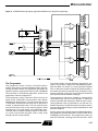
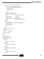
An Example Application
The application shown in Figure 1 is a
simple implementation of a moving display. This application was selected for its
simplicity and ability to show graphically
the results of in-system programming.
The text to be displayed is programmed
into the AT89S8252 microcontroller as
part of its firmware, and can be changed
by reprogramming the device.
The displayed text is presented in one of
two modes, selected by a switch. In the
first mode, one character at a time
enters the display from the right and
moves quickly to the left through each
element of the display to its final position
in the assembled message. In the second mode, the message moves through
the display, from right to left, with the display acting as a window onto the message. This mode is familiar as the
method often used in displays of stock
prices.
The text is displayed on four DL1414T,
four-element, 17-segment alphanumeric
displays with integral decoders and drivers. This yields 16 total display elements, each capable of displaying digits
0-9, the upper case alphabet, and punctuation characters. The displayable character codes are ASCII 20-5F (hexadecimal).
A power-on reset circuit and a 6-MHz
crystal complete the application. Neither
external program memory nor external
data memory is used.
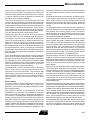
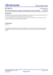
Modifications to the Application to
Support In-System Programming
The AT89S8252 microcontroller features
an SPI port, through which on-chip Flash
memory and EEPROM may be programmed. To program the microcontroller, RST is held high while commands,
addresses and data are applied to the
SPI port. For command format and timing requirements, refer to the Atmel
AT89S8252 Microcontroller data sheet.
Figure 2 shows the example application
modified for in-system programming.
The microcontroller reset circuit has
been eliminated and RST is controlled
by the programmer. The absence of a
reset circuit requires that the programmer reset the microcontroller when
power is first applied to the application.
An optional connection (SHUTDN) to an
AT89S8252 interrupt input has been provided to allow the programmer to signal
the microcontroller prior to programming.
The resident firmware responds to the
inter rupt by d ispl ayi ng a m ess age
(“PROGRAMMING”) indicating that programming is in progress.
A simple latch, composed of four OR
gates, has been added between the outputs of the microcontroller and the display control inputs. The latch holds the
display control signals inactive when
RST is asserted, eliminating erratic operation of the displays during programming. No isolation of the display address
or data inputs is required, since these
inputs are ignored by the displays when
the control signals are inactive. After
programming, when RST is deasserted,
the microcontroller I/O ports are high as
Microcontroller
Application
Note
Microcontroller
0898A-A–12/97
5-73
the latch becomes transparent. Since the display control
inputs are inactive high, the display contents are not disturbed until the new firmware writes the displays. Although
not essential in this application, it might be imperative in
some applications that the state of the peripheral circuitry
not be disturbed during programming.
Finally, programmer access has been provided to three
AT89S8252 SPI port pins: P1.5/MOSI, P1.6/MISO and
P1.7/SCK. SPI port pin P1.4/SS is not used during programming. In the example application, the SPI port pins are
Figure 1. AT89S8252 Moving Display Application Example
5-74
Microcontroller
available for use in programming the microcontroller. Applications which utilize the SPI port pins must be modified by
the addition of circuitry which will isolate the SPI port when
RST is asserted, freeing the pins for use in programming
the microcontroller. Circuitry which is added to support programming must appear transparent to the application during normal operation.
The code for the modified display application is shown in
Appendix 2.
Microcontroller
Figure 2. AT89S8252 Moving Display Application Modified for In-System Programming
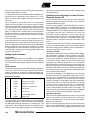
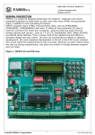
The Programmer
The programmer shown in Figure 3 interfaces with a
modem, from which it receives packetized data. After dissecting the data packets, the programmer generates the
signals required to program the data into the AT89S8252
microcontroller in the modified application. Code for the
programmer is shown in Appendix 3.
The programmer circuitry consists of little more than an
Atmel 20-pin AT89C2051 microcontroller and a Maxim
MAX232 line driver/receiver. The microcontroller runs at
11.0592 MHz, which allows the serial port to operate at a
number of standard baud rates. The line driver/receiver
produces RS-232 levels at the modem interface while
requiring only a 5-V power supply. The AT89C2051 microcontroller does not support external program or data memory, which requires that program code be kept small
enough to fit into on-chip memory.
The serial interface, through which the programmer connects to the modem, supports two handshaking signals,
DTR and DSR. On power up, the programmer asserts
DTR, to which the modem responds by asserting DSR. If
the modem should fail to respond to any command, including the command to hang up, the programmer deasserts
DTR, which forces the modem to hang up.
The programmer controls the modem by sending ASCII
command strings over the serial interface, to which the
modem responds with Hayes-style ASCII numeric codes.
The programmer code is optimized for use with the U.S.
Robotics Sportster 14,400 baud external modem used in
the test configuration and may require modifications if used
with other modems.
Since a reset circuit is absent from the modified application,
the programmer provides the power-on reset function to the
AT89S8252 microcontroller. The programmer powers up
with RST asserted, resetting the microcontroller. Some
5-75
time later, RST is deasserted under firmware control, allowing the application microcontroller to run normally. When
programming is required, the programmer again asserts
RST.
Figure 3. AT89S8252 Programmer
During programming, the programmer outputs serial data
on the MOSI pin, synchronized to a software-generated
clock output on the SCK pin. Serial data is input on the
MISO pin, also synchronized to SCK. The maximum frequency of SCK must be less than 1/40th the crystal frequency of the AT89S8252 microcontroller being programmed, as specified in the AT89S8252 data sheet. The
documented code produces a maximum SCK frequency of
approximately 90 KHz, permitting a minimum AT89S8252
crystal frequency of approximately 3.6 MHz.
Remote Programming Over a Standard
Telephone Line
The programmer and modified application described previously are connected to a phone line through a modem at a
remote site. Using a personal computer with a modem, a
user can upload code containing a new message, which is
programmed into the AT89S8252 microcontroller in the
application. When programming is complete, the microcontroller executes the new firmware, which displays the new
message.
Local Station
The local station in the test configuration consists of an IBM
PC AT-compatible personal computer with a Cardinal
MVPV34ILC 33,600 baud internal modem. Any modem
may be used, as long as it is compatible with the data com-
5-76
Microcontroller
munications software and matches the data rate and error
correction protocols of the modem at the remote site.
Procomm Plus for Windows, version 3.0, a commercial
data communications package, is used to configure the
modem, set up communications parameters, and establish
a link with the remote modem. Procomm Plus includes a
macro language called ASPECT, which allows the user to
write and compile scripts which implement custom file
transfer protocols. A simple ASPECT script was written to
read the contents of a code file and upload it to the remote
programmer. The ASPECT script is shown in Appendix 4.
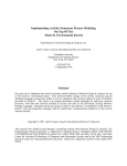
The file transfer protocol (FTP) implemented is a simple
send-and-wait, packet-oriented protocol. The FTP transmit
and receive modes are diagrammed in the flowcharts in figures 4 and 5, respectively. The computer sends each
packet without flow control and waits for a response. The
programmer may acknowledge the packet by sending an
ACK or may negatively acknowledge the packet by sending
a NAK. Upon receipt of an ACK, the computer sends the
next packet. If the clone receives a NAK, it resends the
same packet. Transmission proceeds in this manner until
the entire file has been transferred.
The programmer might respond to a packet by sending a
CAN, which indicates that a non-recoverable error has
occurred and that the computer should immediately abort
the file transfer. If the programmer fails to respond to a
Microcontroller
packet within a limited period of time, the computer will
resend the same packet. The computer will continue to
resend the same packet until a valid response is received
or until the allowed number of attempts is exceeded, at
which time the file transfer is aborted.
The send-and-wait nature of the FTP allows the time
required for the programmer to program the packet data
into the application microcontroller to be easily absorbed.
Programming verification requires no explicit command or
result codes, or additional data transfers. The programmer’s response to a packet reflects the result of the programming verification operation performed by the programmer: ACK indicates success, CAN indicates failure.
Hexadecimal object file format (Intel hex) was chosen as
the format of the files to be uploaded to the programmer.
The records in a hex file serve, unchanged, as the packets
in the FTP described above; no service fields need to be
added. The fields in Intel hex file records are shown in
Appendix 1. The colon which begins each record serves as
the packet signature field. The load address field serves as
the packet sequence number. A checksum is provided as
the last field in each record. Since 7-bit ASCII coding is utilized, the eighth bit of each byte is available to be used for
parity checking.
Since the AT89C2051 microcontroller in the programmer
does not utilize external data memory, necessary packet
buffering must be done using internal RAM. Limited memory precludes the use of conventional FTPs which utilize
packets of 128 bytes or more. The hex packet format used
in this application limits packet data fields to 16 or fewer
entries, requiring little memory for buffering.
A disadvantage of the hex packet format is the use of
ASCII, which requires each program data byte to be
expressed as two hex characters. This demands that
nearly twice as many bytes be transferred as might otherwise be required. This is not a severe limitation, however,
since typical file transfer times are on the order of a few
seconds.
Remote Station
The remote station in the test configuration consists of the
pr og r amm er a nd mo di fi ed ap pli c ati on , p re v iou sl y
described, connected to a U.S. Robotics Sportster 14,400baud external modem.
After power is applied, the programmer resets the
AT89S8252 microcontroller in the application, and then
sets its control outputs inactive, allowing the application to
run normally. The programmer configures the modem to
answer incoming calls and puts itself to sleep. While the
programmer sleeps, the modem monitors the phone line,
waiting for an incoming call. When a call is detected, the
modem answers and attempts to establish communication
with the caller. If a connection is established, the modem
sends a connect code to the programmer, waking it up. The
programmer verifies the connect code and begins polling
for a valid packet header. Invalid connect codes are
ignored.
Incoming packets must arrive fewer than 30 seconds apart,
or the modem hangs up and the programmer returns to
sleep, waiting for the next call. If the caller hangs up, the
30-second period must expire before another call will be
answered. Calls incoming during the reset delay period are
ignored.
If a valid packet header is received prior to the expiration of
the reset delay period, the programmer will attempt to read
and validate the incoming packet. At any time during
packet reception, an invalid character, parity error or timeout during character reception will cause the partial packet
to be declared invalid and discarded.
Two packet types are defined: data and end-of-file. A data
packet contains five fields in addition to the packet header,
one of which is a variable length data field. The data field
contains program data to be written into the application
microcontroller. The load address field contains the
address at which the data is to be written. The end-of-file
packet contains the same fields as the data packet, except
that the data field is empty. This packet type has special
meaning to the programmer, as explained below.
Any packet which contains an invalid record type, record
length or checksum is invalid. Program data accumulated
during the processing of an invalid packet is discarded. The
programmer sends a NAK to the computer to signal reception of an invalid packet and resumes polling for a valid
packet header.
Receipt of the first valid data packet causes the programmer to interrupt the application microcontroller. The microcontroller responds to the interrupt by abandoning its usual
routine and displaying a message (“PROGRAMMING”)
indicating that programming is taking place. If this is the
first valid data packet since power was applied or an endof-file packet was received, the programmer asserts the
control signals necessary to place the microcontroller into
programming mode.
The first and subsequent valid data packets are dissected
as they are received and the data which they contain is programmed into the application microcontroller at the address
indicated in the packet load address field. After programming, the data is read back from the microcontroller and
verified against the received packet data. If programming
was successful, the programmer sends ACK to the computer. The programmer then resumes polling for a valid
packet header, subject to the thirty second reset delay.
If programming fails, the programmer sends CAN to signal
the computer to abort the file transfer. The modem hangs
up and the programmer returns to sleep, waiting for the
next call. The application microcontroller is left in program-
5-77
ming mode, preventing it from executing the incomplete or
invalid firmware which it contains.
It is important to note that invalid packets are NEVER programmed into the application microcontroller. To do so
might over-write valid program data which could not be
recovered.
Upon receipt of an end-of-file packet, the programmer
returns its control outputs to the inactive, power-on state,
allowing the application microcontroller to begin execution
of its new firmware. The programmer then resumes polling
for a valid packet header, subject to the 30-second reset
delay. If a valid packet is received prior to the expiration of
the 30-second delay, another programming cycle begins,
which can only be terminated by the reception of a valid
end-of-file packet.
If the reset delay expires prior to the reception of a valid
end-of-file packet, the modem will hang up and the programmer will return to sleep, waiting for the next call. In this
case, the application microcontroller is left in programming
mode, preventing it from executing its firmware. To return
the application to normal operation, another call must be
received, and a valid program file downloaded, terminated
by an end-of-file packet.
Setting Up the Hardware
Local Station
Install the selected modem into the IBM PC AT-compatible
computer and connect it to a standard analog telephone
line. The modem must support a data rate of at least 9600
baud.
Remote Station
Connect the programmer and modified display application
to the U.S. Robotics Sportster 14,400 baud external
modem. Connect the modem to a standard analog telephone line and set the modem switches as indicated below.
Modem switch settings:
1
UP
DTR normal
2
DOWN
Numeric result codes
3
DOWN
Display result codes
4
DOWN
Suppress command echo
5
UP
Auto answer
6
UP
CD normal
7
UP
Load NVRAM defaults
8
DOWN
Smart mode
Turn the modem on and apply power to the programmer
and display application. The microcontroller in the application will begin executing its firmware, if it contains any. The
programmer will initialize the modem, as indicated by the
activity on the modem status indicators. If it should become
5-78
Microcontroller
necessary to reinitialize the modem, briefly interrupt power
to the programmer.
Installing and Configuring Procomm Plus for
Windows, Version 3.0
Install Procomm Plus as instructed in the User Manual.
When prompted to specify the modem in use, select the
installed modem from the list.
Put the provided ASPECT script (ATX.WAX) into the Procomm Plus ASPECT directory. If the default directories
were utilized during installation, the correct directory is:
\PROWIN3\ASPECT.ATX.WAX is the executable ASPECT
script which results from compiling the source file
ATX.WAS, shown in Appendix 4. Source files may be
edited from within Procomm Plus using the ASPECT Editor, available in the Tools menu. The ASPECT Editor provides the option to compile a source file in the Editor Tools
menu.
Launch Procomm Plus and create a Connection Directory
entry for the remote station. Under Port Settings, set the
baud rate to 9600, parity to EVEN, number of data bits to 7,
number of stop bits to 1, plex to FULL.
Creating a Hex File
The example source code for the modified display application (Appendix 2) contains a string at location “usr_msg”
which is written repeatedly to the alphanumeric displays.
The user may substitute a different message, as long as it
is enclosed in single quotes and is null-terminated. Long
messages may require that the value in the subsequent
ORG directive be increased to prevent the message from
being over-written by code. The message may contain only
characters with ASCII codes from 20-5F (hexadecimal).
The modified source code may then be assembled, linked
and an Intel hex file produced.
During the development of this application note, code was
assembled and hex files generated utilizing the tools in a
vintage copy of the Intel MCS-51 Software Development
Package for the IBM PC. The source code may require
cosmetic changes for compatibility with other assemblers
and software tools. It is especially important to note that
variations exist in Intel hex file format. This application
requires that record data fields be limited to 16 or fewer
entries and that address fields contain 4 hex digits. The
user must verify that the hex files produced by the selected
tools conform to the format documented in Appendix 1.
Uploading a Hex File
Launch Procomm Plus and select the correct entry from the
list box in the toolbar to dial the remote site. If the line is
busy and remains busy for more than 30 seconds, the programmer must be reset.
After a connection with the remote site has been established, run the ATX ASPECT script by selecting it from the
list box in the toolbar. When prompted by the script, enter
Microcontroller
the path and file name (including extension) of the hex file
to upload to the programmer at the remote site. The programmer must receive the first record from the file within 30
seconds of the time the connection was established or it
will hang up and the user will be required to redial.
During the data transfer, data and status information is displayed in the Procomm Plus Terminal Window. If the transfer completes successfully, the message “End of File” will
appear in the Terminal Window. The user has 30 seconds
from the appearance of messages “End of File” or
“EXCESSIVE RETRIES: UPLOAD ABORTED” to rerun the
script and upload another file, if desired, before the programmer hangs up. If the message “UPLOAD ABORTED
BY REMOTE” appears, the programmer has hung up and
the user must redial before uploading another file.
5-79
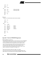
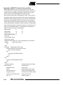
Appendix 1: Intel Hex File Definition
Each record in hexadecimal object file format (Intel hex) contains the following fields:
<:> <rec length> <load address> <rec type> <data> <checksum>
The colon is the record header.
The record length field consists of two hex digits, and represents the number of entries in the data field.
The load address field consists of four hex digits, and indicates the absolute address at which the data in the data field is t o
be loaded.
The record type field consists of two hex digits, which are always zero in data records.
The data field contains from one to 16 pairs of hex digits.
The last two hex digits are a checksum on the record length, load address, record type, and data fields. The sum of the
binary equivalents of these fields and the checksum itself is zero.
Each record in the file is terminated by a carriage return (0D hex) and line feed (0A hex).
A type one record marks the end of the file. The record always contains “:00000001FF”.
Appendix 2: Code for Modified Display Application
NAME LEDShow1
; Displays predefined text strings on the LED display in one of two modes.
; The display mode can be changed at run time with the switch.
;
; The program may be interrupted by External Interrupt 1. This will cause the
; processor to display a string and enter a wait loop with interrupts disabled.
; Only reset will restore normal operation. This facility is provided so that
; the programmer can trigger an orderly shutdown before reprogramming the part.
;
; The LED display consists of four devices of four elements each,
; for a total display capacity of 16 characters.
; The display devices are numbered 0 to 3, from the right.
; The display elements are numbered from 0 to 3, from the right.
; Character positions are numbered 1 to 16, from the right.
NDEVS
EQU 4
NELMS
EQU 4
SPACE
EQU 20h
DSEG AT 60h
stack:DS 20h
SWITCH BIT p1.0
CSEG
ORG 0000h
jmp init
ORG 0003h
reti
ORG 000bh
reti
ORG 0013h
5-80
; number of devices
; number of elements in each device
; blank
; stack origin
; stack depth
; display mode select input
; power on/reset vector
; external interrupt 0 vector
; undefined
; timer 0 overflow vector
; undefined
; external interrupt 1 vector
Microcontroller
Microcontroller
jmp shutdown
ORG 001bh
reti
ORG 0023h
reti
ORG 30h
; timer 1 overflow vector
; undefined
; serial I/O interrupt vector
; undefined
; begin constant data space
pgm_msg: DB ' PROGRAMMING', 0
usr_msg: DB ' ATMEL AT89S8252 CMOS MICROCONTROLLER'
DB ' WITH FLASH MEMORY AND SPI PORT', 0
ORG 0100h
; begin code space
USING 0
; Register bank 0 (RB0)
init:
mov sp, #(stack-1)
; initialize stack pointer
setb IT1
; ext 1 interrupt edge triggered
mov IE, #10000100b
; enable ext 1 and global interrupts
m0:
jb SWITCH, m1
; check position of switch
call rotate_msg
; display message
jmp m0
; again
m1:
call shift_msg
; display message
mov a, #3
; pause 3 sec between displays
call delay_sec
;
jmp m0
; again
shutdown:
; Respond to interrupt generated by serial programmer.
clr ea
; prevent interrupts
mov dptr, #pgm_msg
; point to message
call show_string
; display message
jmp $
; wait for reset
show_string:
; Display null-terminated string pointed to by DPTR. The string is
; left-justified in the display. If the length of the string exceeds
; the number of display positions the excess characters are ignored.
call clear_display; begin by blanking display
mov b, #(NDEVS*NELMS) ; total display positions
gs1:
clr a
mov ca, @a+dptr;
jz gs2
call put_char
; get char
; done if string terminator
; display char at position in B
5-81
inc dptr
djnz b, gs1
gs2:
ret
clear_display:
; point to next char
; done when last position is filled
; Fill display with blanks.
; All registers preserved.
push acc
push b
mov b, #(NDEVS*NELMS) ; total display positions
c1:
mov a, #SPACE
call put_char
djnz b, c1
pop b
pop acc
ret
; write space char
; do all positions
shift_msg:
; Display null-terminated string. Each character in the string,
; in turn, enters the display from the right and is moved quickly
; through each element of the display to its final position.
; The string may contain any number of characters, including none.
; If the length of the string exceeds the number of display
; positions, the excess characters are ignored.
call
mov
mov
ps1:
mov
ps2:
clr
movc
jz
call
mov
call
mov
clr
subb
jnc
mov
call
5-82
clear_display
; begin by blanking display
r5, #(NDEVS*NELMS) ; total display positions
dptr, #usr_msg
; point to message
b, #1
a
a, @a+dptr
ps4
put_char
a, #25
delay_ms
a, b
c
a, r5
ps3
a, #SPACE
put_char
; first display position
; get char
; done if string terminator
; display char at position in B
; 25 ms
; delay so char can be seen
; set up for compare
; ready for subtraction
; compare next position to final
; jump if char is in final position
; blank out char
Microcontroller
Microcontroller
inc
jmp
ps3:
inc
djnz
ps4:
ret
b
ps2
; next position
dptr
r5, ps1
; point to next char
; final position for next char
rotate_msg:
; Display null-terminated string. The string moves through the
; display, from right to left, with the display acting as a window
; onto the string. The string may contain any number of characters,
; including none.
mov
clr
movc
jz
call
dptr, #usr_msg
a
a, @a+dptr;
dd11
clear_display
; point to string
; get first char
; blank display and exit if null string
; begin by blanking display
; Phase I. Shift the string into the display from the
; right until the first character is in the left-most
; display element. If the string has fewer characters than
; the display has elements, fill the balance with blanks.
mov
dd1:
mov
mov
inc
dd2:
clr
movc
jz
call
inc
djnz
jmp
dd3:
mov
call
djnz
dd5:
mov
r7, #0
; loop counter, one pass per element
dptr, #usr_msg
b, r7
b
; point to string
; character position
; adjust
a
a, @a+dptr;
dd3
put_char
dptr
b, dd2
dd5
; get next char
a, #SPACE
put_char
b, dd3
; jump if string terminator
; display char at position in B
; point to next char
; loop until all positions written
; next pass
; encountered end of string
; pad balance of display with blanks
; display char at position in B
; next position
a, #150
; 150 ms
5-83
call
delay_ms
; delay so string can be seen
inc
r7
; next pass
cjne
r7, #(NDEVS*NELMS), dd1 ; loop until all elements done
; Phase II. Shift the string THROUGH the display from
; the right until the last character is in the left-most
; display element. If the string has fewer characters than
; the display has elements, pad the balance with blanks.
mov
inc
dd6:
clr
movc
jz
push
push
mov
dd7:
clr
movc
jz
call
inc
djnz
jmp
dd8:
mov
call
djnz
dd10:
pop
pop
inc
mov
call
jmp
dd11:
call
mov
call
ret
dptr, #usr_msg
dptr
; point to string
; start with the second char
a
a, @a+dptr;
dd11
dpl
dph
b, #(NDEVS*NELMS)
; get char
a
a, @a+dptr
dd8
put_char
dptr
b, dd7
dd10
; blank display and exit if string end
; save string pointer
; total char positions
a, #SPACE
put_char
b, dd8
; get next char
;
; jump if string terminator
; display char at position in B
; point to next char
; loop until all positions written
; next pass
; encountered end of string
; pad balance of display with blanks
; display char at position in B
; next position
dph
dpl
dptr
a, #150
delay_ms
dd6
; restore string pointer
;
; point to next char
; 150 ms
; delay so string can be seen
; process next char
clear_display
a, #150
delay_ms
; blank display
; 150 ms
; delay
put_char:
; Display character in A at position indicated in B.
5-84
Microcontroller
Microcontroller
; All registers preserved.
push
push
mov
acc
b
p0, a
; move character to output port
; Calculate device and element from display position.
mov
dec
mov
div
mov
a, b
a
b, #NELMS
ab
p2, #0ffh
; position 1..n
; convert to 0..n-1
; elements per device
; A= device, B= element
; clear display control port
cjne
mov
jmp
a, #0, s1
a, #00010000b
s5
; check device number
; device 0 select
cjne
mov
jmp
a, #1, s2
a, #00100000b
s5
; device 1 select
cjne
mov
jmp
a, #2, s3
a, #01000000b
s5
; device 2 select
cjne
mov
jmp
a, #3, s4
a, #10000000b
s5
; device 3 select
jmp
init
; undefined device, restart
orl
xrl
mov
orl
mov
pop
pop
ret
a, b
a, #11110000b
p2, a
a, #11110000b
p2, a
b
acc
; add element selector
; invert device selector
; write strobe low
; reset device selector
; write strobe high (latch data)
s0:
s1:
s2:
s3:
s4:
s5:
delay_ms:
; Delay for 1 ms times the value in the accumulator.
5-85
push
push
mov
acc
b
b, #0
djnz
djnz
djnz
pop
pop
ret
b, $
b, $
acc, dd
b
acc
dd:
; 500 us @ 12 MHz
; 500 us @ 12 MHz
delay_sec:
; Delay for 1 second times the value in the accumulator.
push
push
mov
ddd:
mov
call
call
call
call
djnz
pop
pop
ret
acc
b
b, a
a, #250
delay_ms
delay_ms
delay_ms
delay_ms
b, ddd
b
acc
; 250 ms
; 500 ms
; 750 ms
; 1000 ms
END
Appendix 3: Code for AT89S8252 Programmer
NAME AT89S8252_Programmer
; The programmer powers up with the control signals to the target AT89S8252
; inactive, allowing the program in the target to run normally. Upon receipt
; of the first valid data record, the programmer puts the target into write
; mode. The first and subsequent valid records are dissected as they are
; received and their data is written into the target. Receipt of a valid
; end-of-file record terminates programming and resets the target control
; signals, allowing the new program in the target to run.
;
; Each record received is checked for validity. If it is invalid,
; the receiver sends a NAK to the remote system and discards the record.
; Bad records are not programmed into the target AT89S8252. Valid records
5-86
Microcontroller
Microcontroller
; are programmed into the target AT89S8252 and verified. If verification
; succeeds, an ACK is sent to the remote system. If verification fails,
; the receiver sends CAN to abort the upload. Failure to verify is a fatal
; error. The target AT89S8252 will be left in program mode (held reset) so
; that the incomplete or invalid code which it contains cannot be executed.
;
; Incoming records must appear less than 30 seconds apart, or the line
; is dropped in preparation for the next call. If the remote system drops
; the line, the programmer will wait 30 seconds before resetting. Calls
; incoming during this time are ignored.
;
; The programmer manages five lines (SHUTDN, RST, SCK, MOSI, MISO)
; which control the target AT89S8252 and 4 lines which handle the modem
; interface. The AT89S8252 control lines occupy bits of port 1 and the
; modem interface lines bits of port 3, as defined in the EQUates.
;
; Procedures SHOUT (SHift OUT) and SHIN (SHift IN) manage the serial transfer
; of data between the programmer and the target AT89S8252. The serial clock
; is generated and timed by software. The code meets timing requirements
; when executed by an AT89Cx051 microcontroller with a 12-MHz clock.
; Code modifications may be required if a faster clock is substituted.
;
; Two long period timers are implemented utilizing Timer Zero and members of
; register bank one. Timer Zero is configured in 16-bit mode and is loaded
; with an initial count of zero, which yields the maximum delay of 65.5 ms
; (at 12 MHz). The timer is allowed to free-run, generating an interrupt
; each time the count rolls over from FFFF to 0000. At each interrupt, the
; counts in each of the long period timers are decremented if their respective
; overflow flags are not set. If the new count in either long timer is zero,
; the corresponding overflow flag is set. It is not necessary to stop Timer
; 0 or to disable interrupts to reload the long timers, because they will
; not be disturbed by the Timer 0 interrupt service routine whenever their
; overflow flags are set. Because Timer 0 free-runs, it is not possible to
; know where in a period timing of an event begins. Therefore, one additional
; count should be added to the calculated long timer count to guarantee that
; the timed interval is not short.
;
; Long timer 0 is 16 bits, allowing a maximum timed interval of
; over one hour. Long timer 1 is 8 bits, allowing a maximum timed
; interval of 16 seconds.
;
; The programmer software is compatible with the U.S. Robotics Sportster
; 14,400-baud external modem and may require modifications if used with other
; modems. The switches on the modem are set as follows:
5-87
;
; 1 UP DTR normal
; 2 DOWNNumeric result codes
; 3 DOWNDisplay result codes
; 4 DOWNSuppress command echo
; 5 UP Auto answer
; 6 UP CD normal
; 7 UP Load NVRAM defaults
; 8 DOWNSmart mode
;
; Modem switch 7 specifies that the power on and reset configuration be
; loaded from NVRAM profile zero, which must contain the factory default
; hardware flow control template. Other switch settings then override the
; loaded configuration. If NVRAM profile zero does not contain the hardware
; flow control template, it may be restored with the following command
; sequence:
;
; AT&F1&W0<ENTER>
;
; Some of the switch functions can be controlled by software, but making
; use of the switches simplifies the code required to initialize the modem.
; The only additional commands which must be issued to the modem are:
;
; &R1Ignore RTS,
; &A0Disable ARQ result codes.
;
; "&R1" causes the modem to forward incoming data to the programmer regardless
; of the state of RTS. "&A0" suppresses the extended protocol result codes.
; Note that suppression of the codes does not affect the connection. If it is
; desired to disable Error Control, issue the command "&M0".
CR
LF
ACK
NAK
CAN
BAUD_1200
BAUD_2400
BAUD_9600
OK
RINGING
CONNECT_1200
CONNECT_2400
CONNECT_9600
5-88
EQU
EQU
EQU
EQU
EQU
EQU
EQU
EQU
EQU
EQU
EQU
EQU
EQU
0dh
0ah
6h
15h
18h
0e8h
0f4h
0fdh
'0'
'2'
'5'
'10'
'13'
; carriage return
; line feed
; responses to remote system
;
;
; 1200 baud timer reload values
; 2400 baud
; 9600 baud
; modem status codes
;
;
;
;
Microcontroller
Microcontroller
MTRIES
ERASE_1
ERASE_2
ENABLE_1
ENABLE_2
DUMMY
WRITE_CODE
READ_CODE
WRITE_DATA
READ_DATA
lt0_lo
lt0_hi
lt1
index
chksum
temp
kount
DSR_
DTR_
RST
SHUTDN_
SCK
MOSI
MISO
EQU
EQU
EQU
EQU
EQU
EQU
EQU
EQU
EQU
EQU
EQU
EQU
EQU
EQU
EQU
EQU
EQU
BIT
BIT
BIT
BIT
BIT
BIT
BIT
5
0ach
04h
0ach
53h
55h
02h
01h
06h
05h
r2
r3
r4
r0
r5
r6
r7
p3.3
p3.7
p1.7
p1.6
p1.4
p1.3
p1.2
; max attempts to access modem
; erase chip function, first byte
; second byte
; enable write function, first byte
; second byte
; function third byte
; write code memory function (Flash)
; read code memory function
; write data memory function (EEPROM)
; read data memory function
; long timer one low byte
; long timer one high byte
; long timer two only byte
; general purpose index register
; running checksum on record
; temporary storage
; loop counter
; modem control signals
;
; target control signals
;
; serial clock
; serial data out
; serial data in
DSEG AT 20h
flags
LT0F
LT1F
rec_type:
laddr_lo:
laddr_hi:
data_len:
data_buf:
stack:
PCON
DATA 20h
BIT
flags.0
BIT
flags.1
ORG30h
DS
1
DS
1
DS
1
DS
1
DS
32
ORG 60h
DS
20h
DATA 87h
CSEG
ORG 0000h
jmp
init
; misc flags
; long timer 0 overflow flag
; long timer 1 overflow flag
; record type
; record load address, low byte
; record load address, high byte
; record data byte count
; storage for record data field
; stack origin
; stack depth
; address of Power Control register
; (added to enlighten the assembler)
; power on/reset vector
5-89
attn_cmd:
reset_cmd:
init_cmd:
hangup_cmd:
ORG
reti
ORG
jmp
ORG
reti
ORG
reti
ORG
jmp
ORG
DB
DB
0003h
0023h
serial_int
40h
'+++', 0
'ATZ', CR, 0
mov
call
setb
setb
sp, #(stack-1)
initialize
LT0F
LT1F
setb
TI
setb
call
clr
jnc
clr
orl
ET0
modem_init
ET0
m1
EA
PCON, #1
000Bh
timer_int
0013h
001Bh
; external interrupt 0 vector
; undefined
; timer 0 overflow vector
; external interrupt 1 vector
; undefined
; timer 1 overflow vector
; undefined
; serial I/O interrupt vector
; begin constant data space
; modem return to command mode
; modem reset string
; must be last command on line and
; modem returns code before executing
DB
'AT&R1&A0', CR, 0
; modem init string
DB
'ATH', CR, 0
; modem on-hook string
ORG 0080h
; begin code space
USING 0
; register bank 0
init:
; initialize stack pointer
; initialize controller registers
; disable long timer 0
; disable long timer 1
; Initialize the modem.
; set transmit interrupt flag
; (kludge for first use)
; enable timer 0 interrupt
; initialize modem
; disable timer 0 interrupt
; jump if modem init passes
; global interrupt disable
; idle the controller, reset exits
m1:
; Clear pending interrupts before enabling serial interrupts.
jnb
TI, $
; wait for transmitter to clear
clr
TI
; clear transmit interrupt flag
clr
RI
; clear receive interrupt flag
setb
ES
; enable serial ints to wake controller
clr
F0
; clear connect flag / PSW.5 bit
idle:
orl
PCON, #1
; idle the controller, serial int exits
jnb
F0, idle
; return to idle if not connected
; Connection has been established.
5-90
Microcontroller
Microcontroller
; Begin polling for valid record header.
clr
ES
; disable serial interrupts
setb
TI
; set transmit interrupt flag
; (kludge for first use)
clr
F0
; clear program mode flag
setb
ET0
; enable timer 0 interrupt
m2:
call
init_longtimer0
; start 30-second timer
call
jc
cjne
get_char
m8
a, #':', m8
call
jnc
mov
call
jmp
get_record
m4
a, #NAK
send_char;
m2
; get char, 1-second timeout
; try again if parity error or timeout
; try again if not record header
; Found header, process hex record.
; load and dissect record
; jump if record is good
; tell sender record is bad
m3:
; next record
m4:
cjne
a, #0, m6
; jump if record is not type zero
; Process record type zero (data).
jb
F0, m5
; jump if target is in write mode
call
shutdown
; notify target of impending doom
call
erase_chip
; erase target
call
set_pgm
; place target in write mode
setb
F0
; flag target in write mode
;
m5:
call
call
jnc
mov
call
jmp
write_record
verify_record
m7
a, #CAN
send_char;
m9
; program data into target
; verify program data
; jump if verify OK
; tell sender to abort
; hang up and reset for next call
m6:
; Process record type one (end-of-file).
call
clear_pgm
; take target out of write mode
clr
F0
; flag target not in write mode
m7:
mov
call
jmp
a, #ACK
send_char
m2
; tell sender record OK
;
; next record
jnb
LT0F, m3
; poll until timer times out
; timer timed out or upload cancelled
m8:
m9:
5-91
call
clr
jmp
hang_up
ET0
m1
; break the connection
; disable timer 0 interrupt
; return controller to idle
serial_int:
; Process serial interrupt. Interrupts due to transmit done are
; cleared and ignored. If interrupt is due to receive data ready,
; check for a modem connect code, and set the connect flag.
; The procedure includes code for identifying both single- and
; double-character connect codes, but both may not be active
; simultaneously. The code for identifying double-character
; connect codes is dependent on the receive baud rate.
; Serial interrupts are enabled elsewhere.
clr
F0
; clear connect flag
clr
TI
; clear transmit interrupt flag
jnb
RI, si2
; exit if not receive data ready
mov
a, SBUF
; get character into accumulator
mov
c, p
; carry set for odd parity (error)
jc
si1
; ignore char if parity error
; Test for single-character 1200-baud connect code.
anl
a, #7fh
; strip off parity (eighth) bit
cjne
a, #CONNECT_1200, si1
; ignore char if wrong code
; Test for double-character 9600-baud connect code.
anl
a, #7fh
; strip off parity (eighth) bit
cjne
a, #(HIGH CONNECT_9600), si1; ignore wrong char
clr
RI
; reset receive flag
mov
a, #2
; expect next char in about 1 ms
call
delay_ms
; wait for next char
jnb
RI, si2
; exit if not receive data ready
mov
a, SBUF
; get character into accumulator
mov
c, p
; carry set for odd parity (error)
jc
si1
; ignore char if parity error
anl
a, #7fh
; strip off parity (eighth) bit
cjne
a, #(LOW CONNECT_9600), si1; ignore wrong char
setb
F0
; set connect flag
;;
;;
si1:
clr
RI
; reset receive flag
si2:
reti
timer_int:
; Process Timer Zero interrupt, which occurs about every 65.5 ms.
; Each long timer count is decremented if its overflow flag is clear.
; When a long timer count reaches zero, its overflow flag is set.
5-92
Microcontroller
Microcontroller
; Counts are reloaded and overflow flags are reset elsewhere.
push
setb
jb
cjne
dec
psw
RS0
LT0F, ti2
lt0_lo, #0, ti1
lt0_hi
; save flags
; select register bank one
; skip if long timer 0 overflow set
; test low byte
; low byte is zero, borrow from high
djnz
cjne
lt0_lo, ti2
lt0_hi, #0, ti2
setb
LT0F
; dec low byte, skip if not zero
; low byte is zero, test high byte
; both bytes equal zero
; set overflow flag
jb
djnz
setb
LT1F, ti3
lt1, TI3
LT1F
; skip if long timer 1 overflow set
; decrement count and skip if not zero
; count is zero, set overflow flag
pop
reti
psw
; restore flags and reg bank zero
ti1:
ti2:
ti3:
initialize:
; Initialize controller registers and I/O lines.
mov
mov
mov
mov
;;
PCON, #0
; initialize power control register
IE, #0
; deactivate all interrupts
SCON, #01000000b; serial port mode 1
TMOD, #00100001b; timer 1 8-bit auto-reload,
; timer 0 16-bit
mov
TH1, #BAUD_1200 ; timer 1 reload value
mov
TH1, #BAUD_9600 ; timer 1 reload value
mov
TCON, #01000000b; start timer 1
mov
TL0, #0
; set timer 0 to max count
mov
TH0, #0
;
setb
TR0
; start timer 0
setb
REN
; enable serial reception
setb
EA
; global interrupt enable
; Initialize I/O lines.
setb
DTR_
setb
SHUTDN_
setb
MISO
setb
MOSI
clr
SCK
clr
RST
; remove reset from target
ret
5-93
modem_init:
; Reset and initialize the modem.
; Return with carry set if modem fails to respond as expected.
clr
DTR_
; assert DTR to talk to modem
; First must ensure that the modem is in command mode.
mov
a, #1
; wait 1 second
call
delay_sec
;
mov
dptr, #attn_cmd
; point to attention string
call
send_string
; transmit string
mov
a, #1
; wait 1 second
call
delay_sec
;
; Reset modem, causing the switches to be read.
mov
dptr, #reset_cmd
; point to reset string
call
modem_cmd
; transmit string
jc
nn1
; jump on fail
mov
a, #1
; wait 1 second before next command
call
delay_sec
;
; Modem is powered up and on-line.
; Send required software parameters.
mov
dptr, #init_cmd
; point to init string
call
modem_cmd
; transmit string
jnc
nn2
; jump on pass
nn1:
; Modem is misbehaving, so deactivate it.
; The controller must be reset to exit this state.
setb
DTR_
; deassert DTR to deactivate modem
nn2:
ret
hang_up:
; Force the modem to drop the line.
; First must return the modem to command mode.
mov
a, #1
; wait 1 second
call
delay_sec
;
mov
dptr, #attn_cmd
; point to attention string
call
send_string
; transmit string
mov
a, #1
; wait 1 second
call
delay_sec
;
; Issue command to hang up.
mov
dptr, #hangup_cmd ; point to hang up string
call
modem_cmd
; transmit string
jnc
hh
; jump on pass
; The polite way didn't work, so drop DTR.
5-94
Microcontroller
Microcontroller
; The controller must be reset to exit this state.
setb
DTR_
; force modem to drop the line
hh:
ret
modem_cmd:
; Transmit command string to modem and validate the response.
; Return with carry set if modem fails to respond as expected,
; or if excessive parity errors or receive timeouts occur.
; Valid responses consist of a byte code followed by a carriage
; return. Parity errors and timeouts cause the command to be
; resent. Expected delays for command responses are absorbed
; by GET_CHAR. On entry, DPTR must point to a null-terminated
; command string.
push
mov
b
b, #MTRIES
; number of attempts
call
clr
send_string
RI
; transmit command string
; discard any waiting character
call
jc
cjne
call
jc
cjne
get_char
mm3
a, #OK, mm2
get_char
mm3
a, #CR, mm2
clr
jmp
c
mm4
; receive result code
; jump on parity error or timeout
; loop if response is not valid
; receive carriage return
; jump on parity error or timeout
; loop if response is not valid
; valid response complete
; clear error flag
; return
mm1:
mm2:
mm3:
djnzb, mm1
setb
c
; resend command
; out of retries, set error flag
mm4:
pop
ret
b
send_string:
; Transmit string pointed to by DPTR.
; String may be of any length, but must be null-terminated.
push
push
push
acc
dpl
dph
5-95
ss1:
clr
movc
jz
call
inc
jmp
a
a, @a+dptr
ss2
send_char
dptr
ss1
pop
pop
pop
ret
dph
dpl
acc
; get character
; check for terminator
; send character
; point to next character
ss2:
send_char:
; Wait for transmitter to clear, add even parity bit to character
; in accumulator and transmit it. Does not wait for transmitter
; to clear before returning.
jnb
clr
push
movc,
mov
mov
pop
ret
TI, $
TI
acc
p
acc.7, c
SBUF, a
acc
; wait here for transmitter to clear
; clear transmit flag
; save char
; get parity bit
; add parity bit to data
; load character into transmitter
; restore char
get_char:
; Read a character from the serial port and check for even parity.
; Return the character in the accumulator with parity stripped off.
; The routine will wait for approximately 1 second before timing
; out. Return with carry set on parity error or timeout.
jb
call
RI, gc2
init_longtimer1
; jump if char is waiting
; start 1-second timer
jb
jnb
setbc
jmp
RI, gc2
LT1F, gc1
gc3
; exit loop when char received
; loop until timer times out
; set error flag
; return
mov
mov
anl
a, SBUF
c, p
a, #7fh
; get character into accumulator
; carry set for odd parity (error)
; strip off parity (eighth) bit
gc1:
gc2:
5-96
Microcontroller
Microcontroller
clr
RI
; reset receive flag
gc3:
ret
get_byte:
; Read two hexadecimal ASCII characters from the serial port
; and return their binary equivalent in the accumulator.
; Return with carry set if either character was invalid or
; contained a parity error.
call
jc
call
jc
swap
mov
call
jc
call
jc
orl
get_char
gb
ascii2bin
gb
a
b, a
get_char
gb
ascii2bin
gb
a, b
; get first char from serial port
; exit on parity error
; convert hex to binary
; exit on invalid char
; first hex digit times 16
; save value
; get second char from serial port
; exit on parity error
; convert hex to binary
; exit on invalid char
; combined binary equivalent
gb:
ret
ascii2bin:
; Convert hexadecimal digit in the accumulator to its binary
; equivalent and return it in the accumulator. Valid hex digits
; are 0..9 and A..F (upper case only). Return with carry set
; if the character received is not a valid hex digit.
mov
clr
subb
jnc
mov
clr
subb
jmp
temp, a
c
a, #('9'+1)
a1
a, temp
c
a, #'0'
a4
; save char
; prepare for subtraction
; compare to '9'
; jump if char above '9'
; get original char
; prepare for subtraction
; compare to '0'
; return error if char below '0'
; else binary value in accumulator
mov
subb
cpl
jc
a, temp
a, #('F'+1)
c
a4
; get original char
; compare to 'F'
; invert error flag
; return error if char is above 'F'
a1:
5-97
a2:
mov
subb
jc
a, temp
a, #'A'
a4
; get original char
; compare to 'A'
; return error if char is below 'A'
add
a, #10
; adjust binary value
a3:
a4:
ret
get_record:
; Read and dissect record. Two record types are accepted: data and
; end-of-file. If the record type is data, the appropriate values
; are extracted and stored. If the record type and checksum are
; valid, the carry bit is cleared and the record type is returned
; in the accumulator. Return with carry set to signal an invalid
; record type, checksum error, or other problem. Errors returned
; by routine GET_BYTE (invalid char or parity) cause an immediate
; return with carry set.
mov
chksum, #0
; clear running checksum
call
get_byte
; get record data length field
jc
rr4
; jump on error
mov
data_len, a
; save data length
clr
c
; prepare for subtraction
subb a, #(16+1)
; data length limited to 16 bytes
jnc
rr4
; jump if max size exceeded
call
get_byte
; get high byte of load address field
jc
rr4
; jump on error
mov
laddr_hi, a
; save it
call
get_byte
; get low byte of load address field
jc
rr4
; jump on error
mov
laddr_lo, a
; save it
call
get_byte
; get record type field
jc
rr4
; jump on error
mov
rec_type, a
; save type
cjne
a, #0, rr2
; jump if not type zero (data)
; Process data in data type record.
mov
index, #data_buf
; pointer to data buffer
mov
kount, data_len
; byte counter
rr1:
call
jc
mov
add
5-98
get_byte
rr4
@index, a
a, chksum
Microcontroller
; get data from serial port
; jump on error
; save data in buffer
; update checksum
Microcontroller
mov
inc
djnz
jmp
chksum, a
index
kount, rr1
rr3
;
; point to next location
; decrement byte count and loop
; done with data, do checksum
mov
cjne
a, rec_type
a, #1, rr4
; get record type
; jump if not type one (end-of-file)
rr2:
rr3:
; Process checksum.
call
get_byte
jc
rr4
add
a, chksum
add
a, data_len
add
a, laddr_lo
add
a, laddr_hi
add
a, rec_type
jnz
rr4
;
;
;
;
call
jc
call
jc
mov
clr
jmp
; get record checksum
; jump on error
; update running checksum
;
;
;
;
; jump if record checksum is not zero
; Discard CR/LF which terminates record.
get_byte
rr4
get_byte
rr4
a, rec_type
c
rr5
; jump on error
; return record type in accumulator
; no errors
; return
c
; Error: data field too large, invalid type or bad checksum.
; set error flag
; jump on error
rr4:
setb
rr5:
ret
write_record:
; Write the data extracted from the most recently received record
; into the target AT89S8252. Timing delays are enforced by software.
; This routine assumes that the target has already been prepared
; for programming. Returns nothing.
mov
mov
mov
anl
rl
rl
rl
r2, laddr_lo
r3, laddr_hi
a, r3
a, #00011111b
a
a
a
; save low byte of load address
; save high byte of load address
; get high byte of load address
; isolate 5 bits
; move 5 bits to top
;
;
5-99
orl
mov
mov
mov
a, #WRITE_CODE
temp, a
index, #data_buf
kount, data_len
; specify code write function
; save adjusted high byte
; pointer to data buffer
; byte counter
pp1:
mov
a, temp
call
shout
mov
a, r2
call
shout
mov
a, @index
call
shout
mov
a, #3
call
delay_ms
; Next address.
mov
a, r2
add
a, #1
movr2, a
jnc
pp2
; carry out of low byte
mov
a, r3
add
a, #1
mov
r3, a
anl
a, #00011111b
rl
a
rl
a
rl
a
orl
a, #WRITE_CODE
mov
temp, a
; send adjusted high byte of address
;
; send low byte of address
;
; send data from buffer
;
; wait 3 ms
; get low byte of address
; increment low byte
; save incremented value
; jump if no carry out of low byte
; get high byte of address
; increment high byte
; save incremented value
; isolate 5 bits
; move 5 bits to top
;
;
; specify code write function
; save adjusted high byte
pp2:
; Next data.
inc
index
djnz
kount, pp1
ret
; point to next buffer location
; decrement byte count and loop
verify_record:
; Verify the data extracted from the latest record against that
; written into the target AT89S8252. Timing delays are enforced by
; software. This routine assumes that the target has already been
; prepared for programming. Return with carry set if verify fails.
mov
mov
mov
anl
5-100
r2, laddr_lo
r3, laddr_hi
a, r3
a, #00011111b
Microcontroller
; save low byte of load address
; save high byte of load address
; get high byte of load address
; isolate 5 bits
Microcontroller
rl
rl
rl
orl
mov
mov
mov
a
a
a
a, #READ_CODE
temp, a
index, #data_buf
kount, data_len
; move 5 bits to top
;
;
; specify code read function
; save adjusted high byte
; pointer to data buffer
; byte counter
vv1:
mov
a, temp
call
shout
mov
a, r2
call
shout
; Read data and verify.
call
shin
mov
b, @index
cjne
a, b, vv2
jmp
vv3
; send adjusted high byte of address
;
; send low byte of address
;
setb
jmp
; set error flag
; return
; read data
; get record data
; jump on verify fail
; verify OK, do next address
vv2:
c
vv5
vv3:
; Next address.
mov
a, r2
add
a, #1
mov
r2, a
jnc
vv4
; carry out of low byte
mov
a, r3
add
a, #1
mov
r3, a
anl
a, #00011111b
rl
a
rl
a
rl
a
orl
a, #READ_CODE
mov
temp, a
; get high byte of address
; increment high byte
; save incremented value
; isolate 5 bits
; move 5 bits to top
;
;
; specify code write function
; save adjusted high byte
; Next data.
inc
index
djnz
kount, vv1
clr
c
; point to next buffer location
; decrement byte count and loop
; clear error flag
; get low byte of address
; increment low byte
; save incremented value
; jump if no carry out of low byte
vv4:
vv5:
ret
5-101
shout:
; Shift out a byte, most significant bit first.
; SCK expected low on entry. Return with SCK low.
; Called with data to send in A.
push
mov
b
b, #8
rlc
mov
nop
nop
setb
nop
nop
nop
nop
clr
djnz
pop
ret
a
MOSI, c
; bit counter
x42:
SCK
SCK
b, x42
b
; move bit into CY
; output bit
; enforce data setup
;
; raise clock
; enforce SCK high
;
;
;
; drop clock
; next bit
shin:
; Shift in a byte, most significant bit first.
; SCK expected low on entry. Return with SCK low.
; Returns received data byte in A.
push
mov
b
b, #8
setb
mov
rlc
nop
nop
clr
nop
nop
djnz
pop
ret
SCK
c, MISO
a
; bit counter
x43:
SCK
b, x43
b
erase_chip:
; Erase target AT89S8252.
5-102
Microcontroller
; raise clock
; input bit
; move bit into byte
; enforce SCK high
;
; drop clock
; enforce SCK low
;
; next bit
Microcontroller
setb
mov
call
mov
call
mov
call
mov
call
clr
ret
RST
a, #ERASE_1
shout
a, #ERASE_2
shout
a, #DUMMY
shout
a, #10
delay_ms
RST
; force target into reset
; send first byte of erase function
;
; send second byte
;
; send third byte
;
; wait 10 milliseconds
;
; remove reset from target
shutdown:
; Force target to abandon execution of its internal program.
clr
mov
call
setb
ret
SHUTDN_
a, #5
delay_ms
SHUTDN_
; notify target of impending reset
; give target 5 ms to shut down
;
; deassert interrupt
set_pgm:
; Prepare the target AT89S8252 for programming.
setb
RST
; force target into reset
mov
a, #1
; wait 1 ms (arbitrary)
call
delay_ms
;
; Enable writes to code and data memory.
mov
a, #ENABLE_1
; send first byte of enable code
call
shout
;
mov
a, #ENABLE_2
; send second byte
call
shout
;
mov
a, #DUMMY
; send third byte
call
shout
;
ret
clear_pgm:
; Allow target AT89S8252 to resume execution of its own program.
clr
ret
RST
; remove reset from target
init_longtimer0:
; Load and start long timer 0.
5-103
; System Timer 0 count loaded and interrupt enabled elsewhere.
setb
setb
mov
mov
clr
clr
ret
LT0F
RS0
lt0_lo, #0c8h
lt0_hi, #1
RS0
LT0F
; disable counter
; select register bank one
; load 30-second count
;
; back to bank zero
; enable counter
init_longtimer1:
; Load and start long timer 1.
; System Timer Zero count loaded and interrupt enabled elsewhere.
setb
setb
mov
clr
clr
ret
LT1F
RS0
lt1, #17
RS0
LT1F
; disable counter
; select register bank one
; load 1-second count
; back to bank zero
; enable counter
delay_ms:
; Delay for 1 ms times the value in the accumulator.
push
push
mov
acc
b
b, #0
djnz
djnz
djnz
pop
pop
ret
b, $
b, $
acc, dd
b
acc
dd:
; 500 us @ 12 MHz
; 500 us @ 12 MHz
delay_sec:
; Delay for 1 s times the value in the accumulator.
push
push
mov
acc
b
b, a
mov
call
call
a, #250
delay_ms; 250 ms
delay_ms; 500 ms
ddd:
5-104
Microcontroller
Microcontroller
call
call
djnz
pop
pop
ret
delay_ms; 750 ms
delay_ms; 1000 ms
b, ddd
b
acc
END
5-105
Appendix 4: ASPECT Script for Procomm Plus
; PROCOMM ASPECT script to read and transmit an Intel hex file.
; The script does not set up communications parameters, initialize the
; modem, dial out or establish a connection with the receiver; this is
; done manually via the PROCOMM Connection Directory.
; Each record in the hex file is terminated by a CR/LF. The receiver is
; expected to respond with an ACK after each record is validated and
; programmed into the target processor. If the receiver cannot validate
; the record, it responds with a NAK. If the receiver cannot verify the
; record data after programming the target processor, it responds with
; a CAN, which tells the transmitter to abort the upload. The transmitter
; waits 2 seconds between records for a response. If a response is not
; received in the allowed interval, or if the response is other than an
; ACK or a CAN, the record is retransmitted.
#define ACK
6
; ^F
#define NAK
21
; ^U
#define CAN
24
; ^X
#define MAXRETRIES 4
proc main
string filename, record
integer retry, rxcode
sdlgfopen "Select HEX File" "*.hex" single filename; get file name
if failure
; get file name failed
exit
endif
if filename ; validate path and file name
if fopen 0 filename read; open file for read
fgets 0 record; read record
else
errormsg "FILE OPEN FAILED"
exit
endif
else
errormsg "FILE DOES NOT EXIST"
exit
endif
set aspect rxdata on
; script processes receive data
while not feof 0
; check for EOF
termwrites record
; show record
rxflush
; purge pending receive data
transmit record raw
; send record including CR/LF
comgetc rxcode 2
; wait max 2 seconds for answer
call show_rxcode with rxcode ; show received code
retry = 0
; initialize counter
5-106
Microcontroller
Microcontroller
while (rxcode != ACK) && (retry < MAXRETRIES)
if (rxcode == CAN); abort ordered by remote
errormsg "UPLOAD ABORTED BY REMOTE"
fclose 0; close file
set aspect rxdata off
exit
endif
termwrites "Resending record^M^J"
termwrites record; show record
rxflush
; purge pending receive data
transmit record raw
; send record
comgetc rxcode 2
; get response
call show_rxcode with rxcode; show received code
++retry
; advance counter and try again
endwhile
if (rxcode != ACK)
errormsg "EXCESSIVE RETRIES: UPLOAD ABORTED"
fclose 0 ; close file
set aspect rxdata off
exit
endif
fgets 0 record; read next record
endwhile
termwrites "End of file^M^J"
fclose 0
; close file
set aspect rxdata off
exit
endproc
proc show_rxcode
param integer rxcode
; termmsg "%#X`r`n", rxcode
switch rxcode
case -1
termwrites "Timed out^M^J"
endcase
case ACK
termwrites "Received ACK^M^J"
endcase
case NAK
termwrites "Received NAK^M^J"
endcase
case CAN
termwrites "Received CAN^M^J"
endcase
5-107
default
termwrites "Received garbage^M^J"
endcase
endswitch
endproc
5-108
Microcontroller
Microcontroller
Figure 4. FTP Transmit Mode
5-109
Figure 5. FTP Receive Mode
5-110
Microcontroller