Transcript
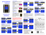
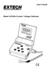
4- to 20mA Current
Loop Simulator
The Current Loop Simulator was developed
to assist maintenance personnel and
integrators in 4–20 mA analog input testing,
troubleshooting and application development.
Device Simulation
Two-Wire Loop
Powered Device
It simulates a 2-wire loop powered transmitter.
Power Supply
12-30V DC
24VDC typical
Five fixed output settings are available:
4 mA, 8 mA, 12 mA, 16 mA or 20 mA.
A specific output selection made by
connecting signal wire to one of the five
output terminals
It is not recommended to connect more than
one output at the same time. If this happened,
maximum current limited to 24mA.
WWW.PLCTOOLS.COM
Product of USA
Typical Simulator Connection
with an External Loop Power
Supply
SPECIFICATION
Current Output
Output Range
Fixed Preset
Output Selection
Output Accuracy
Protection
4mA to 20mA
4 , 8, 12, 16, 20 mA
Terminal
±1% of full scale
or ±0.20mA
Reverse Polarity
Simulator can work with wide range of loads
from 0 to 1000 Ohm, typical analog input
impedance is 250 Ohm. Loads above 500
Ohm require 24V or higher loop power supply
Load Range
A typical 2-wire installation requires a loop
power supply usually provided by an external
24VDC power supply
Currently the device does not carry any
agency approvals and is not compliant with
RoHS.
Some sourcing Analog Input modules can
provide loop power also.
Follow the Analog Input Module specification
for a power supply selection
Typical Simulator Connection
with a Sourcing Analog Input
0-1000 Ohm
250 Ohm typical
Loads over 500 Ohm require 24V or higher
power supply
Do Not Operate Device Unless Area Is
Non-Hazardous
DISCLAIMER
This device is intended to provide general
assistance with current loop debugging, testing
and application development.
It should not be permanently used in live
production systems.
Accordingly, production system must be
tested and commissioned with real instruments
to ensure safe and reliable operation.
IN NO EVENT SHALL THE DEVICE
MANUFACTURER BE LIABLE FOR
ANY DAMAGES OF ANY KIND
INCLUDING
DIRECT,
INDIRECT,
INCIDENTAL, CONSEQUENTIAL, LOSS
OF PROFIT OR DAMAGE.
Important:
Do not use this device for an input
module or instrument calibration.
This device is a simple tester that
provides current signal within a
selected range.
The examples and diagrams in this manual are
included for illustrative purposes only.
Because of the many variables and
requirements associated with any particular
installation, the device manufacturer cannot
assume responsibility or liability for actual use
based on the examples and diagrams.
Before making any decision or taking any
action that might affect your equipment, you
should consult a qualified professional
advisor.