1
MANUAL
MAGNET POWER SUPPLY
SYSTEM 9100
REV.
By
Date
1.0
CSN
12.04.2010
2.0
CSN
18.06.2010
2.1
CSN
19.08.2010
2.2
2.3
CSN
ESHA
05.05.2011
19.12.2012
Description
Initial
Chapter 2.5: Two or more SYSTEM 9100 in
parallel deleted
Chapter 5: AC mains Connector X1. 208VAC pin
connections added
Various
Address
IMPORTANT!
This documentation contains information which
is the property of DANFYSIK A/S, Denmark.
It is submitted to you in confidence that it will not be
disclosed or transmitted to others without DANFYSIK=s
authorisation.
Pages
All
12
57
MAGNET POWER SUPPLY SYSTEM 9100
3
Table of contents
1
PAGE
INTRODUCTION AND SPECIFICATIONS ....................................................................................... 5
1.1
1.2
1.3
2
GENERAL INTRODUCTION ............................................................................................................... 5
SPECIFICATIONS .............................................................................................................................. 6
WARRANTY AND WARRANTY REPAIR. ............................................................................................ 9
UNPACKING AND INSTALLATION............................................................................................... 10
2.1
2.2
2.3
2.4
2.5
3
RECEIVING THE GOODS ................................................................................................................. 10
INSTRUCTIONS FOR UNPACKING .................................................................................................... 10
INSTALLATION REQUIREMENTS ..................................................................................................... 10
INSTALLATION ............................................................................................................................... 11
RS422 OR RS485 MULTIDROP CONFIGURATION ........................................................................... 12
OPERATING INSTRUCTIONS ......................................................................................................... 13
3.1
3.2
SWITCHING ON .............................................................................................................................. 13
OPERATING WITH THE MANUAL CONTROL PANEL ....................................................................... 13
3.2.1
Main power ON / OFF and interlock RESET ...................................................................... 14
3.2.2
Using the Manual Panel Menus ............................................................................................ 14
3.2.3
Front panel controls. ............................................................................................................. 16
3.2.4
The Display .......................................................................................................................... 17
3.2.5
Control Menus ...................................................................................................................... 20
3.2.6
Current setting ...................................................................................................................... 22
3.2.7
Polarity reversal .................................................................................................................... 22
3.3
OPERATING BY RS 232, RS422 OR RS 485 I/O ............................................................................. 24
3.3.1
Setting up the MPS via display board .................................................................................. 24
3.3.2
Data communication............................................................................................................. 36
3.3.3
Termination using RS 422m or RS 485................................................................................ 37
3.3.4
Programming ........................................................................................................................ 38
3.3.5
Software Profile Programming ............................................................................................. 39
3.3.6
Arbitrary point ramp profile method .................................................................................... 40
3.3.7
Equal time slot ramp profile method .................................................................................... 41
3.3.8
Auto Slew Rate Ramp Profile method. ................................................................................ 42
3.3.9
SW limits .............................................................................................................................. 43
3.4
OPERATING IN ANALOG MODE ...................................................................................................... 47
3.4.1
Standard interface / Parallel interface................................................................................... 48
4
THEORY OF OPERATIONS.............................................................................................................. 49
4.1
4.2
4.3
INTRODUCTION .............................................................................................................................. 49
M-PANEL ....................................................................................................................................... 52
I-LOOP, CONTROL, INTERLOCK PCB ............................................................................................ 52
4.3.1
Micro-processor.................................................................................................................... 52
4.3.2
DAC Circuit ......................................................................................................................... 52
4.3.3
ADC Control ........................................................................................................................ 53
4.3.4
Voltage reference.................................................................................................................. 53
4.3.5
DC/DC Converter ................................................................................................................. 53
4.3.6
Seriel Interface...................................................................................................................... 53
4.3.7
Current & Voltage loop ........................................................................................................ 54
4.3.8
Control .................................................................................................................................. 54
4.3.9
Soft start ............................................................................................................................... 54
4.3.10 Interlock................................................................................................................................ 54
4.3.11 Peltier Control ...................................................................................................................... 55
DANFYSIK A/S - DENMARK.
MAGNET POWER SUPPLY SYSTEM 9100
4
4.4
4.5
EMC FILTER .................................................................................................................................. 55
AC INPUT FILTER MODULE ............................................................................................................ 55
4.5.1
Overcurrent breaker .............................................................................................................. 55
4.5.2
Rectifier 3 phase ................................................................................................................... 55
4.5.3
Soft Start Module ................................................................................................................. 55
4.5.4
Capacitor and DC link filter ................................................................................................. 55
4.6
OUTPUT MODULE........................................................................................................................... 56
4.6.1
Output and filter ................................................................................................................... 56
4.6.2
Transformer .......................................................................................................................... 56
4.6.3
PWM controller .................................................................................................................... 56
4.7
AUX POWER SUPPLY ...................................................................................................................... 56
4.7.1
AC line monitor .................................................................................................................... 56
4.7.2
Aux power loop & CPU ....................................................................................................... 56
4.7.3
Aux power FAN ................................................................................................................... 57
4.7.4
Aux power primary............................................................................................................... 57
4.8
DCCT TRANSDUCER ..................................................................................................................... 57
4.9
BIPOLAR OUTPUT STAGE (H-BRIGDE) ........................................................................................... 57
5
SYSTEM 9100 INTERFACE SPECIFICATION: .............................................................................. 58
AC Mains connector X1: ..................................................................................................................... 58
Output X24 and X25 ............................................................................................................................ 58
Analog X108 (D-SUB 25 Pole): .......................................................................................................... 59
SPI – Iset DAC interface X5 (HDMI 19- Pole): .................................................................................. 59
LOCAL CONTROL X6 (D-SUB 9 Pole): ........................................................................................... 60
REMOTE CONTROL X7 (D-SUB 25 Pole): ...................................................................................... 61
Connector X9 (pin 1-4) X8 (pin 6-10) X112 (pin 12-16): ................................................................... 61
Fuseholder F1:...................................................................................................................................... 61
6
MAINTENANCE ................................................................................................................................ 62
6.1
6.2
6.3
7
INTRODUCTION .............................................................................................................................. 62
PREVENTIVE MAINTENANCE ......................................................................................................... 62
ADJUSTMENT AND CALIBRATION .................................................................................................. 62
TROUBLE SHOOTING ...................................................................................................................... 63
DANFYSIK A/S - DENMARK.
MAGNET POWER SUPPLY SYSTEM 9100
5
1
Introduction and specifications
1.1
General introduction
The System 9100 is a DC constant current output Power Supplies designed for applications
requiring very high stability and low noise combined with reliability and ease of operation.
The System 9100 is aimed at correction magnets in ion beam applications based on Danfysik´s
forty years of experience in delivering precision DC Power supplies to industrial and research
laboratory users around the world.
The System 9100 is the new generation of high performance Power Converters suitable for
many high current and voltage applications where size and cost are essential.
Power range of 3 kW, 6 kW, 9 kW and 12 kW , allowing the user to select the most
suitable solution
10ppm stability class using LEM Ultrastab high precision DCCT current transducer to
control the current stability in the power supply
Wide current range from 50 A to 200 A
Low output ripple, internal power modules are parallel connected in pairs with a 180º
phase angle, hereby reducing input and output ripple.
Remote controlled through a serial interface “RS232/RS422/RS485”
DANFYSIK A/S - DENMARK.
MAGNET POWER SUPPLY SYSTEM 9100
6
1.2
Specifications
AC INPUT
Mains, voltage:
Control voltage:
AC voltage variation:
400 VAC, 3 phase, 47 - 63 Hz.
230 VAC, 47-63 Hz.
±10%
See page 58 for connection to AC mains connector.
DC OUTPUT
Power Range
up to 12 kW
Current:
50 A - 100 A - 150 A - 200 A versions
Voltage:
60 V
Regulation Topology:
Constant current regulation
Converter Type:
Primary switching type that operate after the Zero
voltage switch-mode principle
PERFORMANCE
Warm up time (cold):
Warm up time (stand-by):
30 min.
15 min
Drift (long term 8 hours):
±10ppm
Line regulation
± 10% slow, T > 1 min.:
± 1% fast, T > 3 m sec.:
±5ppm
±5ppm
Load regulation
± 10% resistance change:
±5ppm
Output ripple and noise
Voltage – peak to peak:
< 100 mV @ 0-100 kHz
Load Range
Time Constant (L/R):
Inductance (L):
0 - 1 sec
0 - 1 H (standard)
Temperature coefficient
Ambient 15 – 40° C:
5ppm/°C
Ambient 15 – 30° C:
1ppm/°C
Current setting resolution:
20 bit DAC
Current reproducibility:
± 10ppm
Absolute current calibration:
-0 / +400ppm
DANFYSIK A/S - DENMARK.
MAGNET POWER SUPPLY SYSTEM 9100
7
Current readback resolution:
16 bit ADC
Voltage readback resolution:
16 bit ADC
Current control range (setting range):
1 – 100%
Ramp speed (0 – 100%):
0.1 – 10 s (adjustable)*
Current loop bandwidth:
2 – 100 Hz
Voltage loop bandwidth:
>200 Hz
*Ramp speed for the bipolar version is limited in the second and fourth quadrant. See page 22.
CONTROL PANEL
Alphanumeric LCD display:
Preset output current, 6 digits
Actual output current, 5 digits
Output voltage, 2 digits
Interlock status text string
Push buttons and LED's
OFF
Reset (interlock)
ON
Menu
Out of regulation
[A]
[A]
[V]
[Button]/[LED]
[Button]/[LED]
[Button]/[LED]
[Button]
[LED]
Remote control / interfacing
RS232 as standard (RS422 and RS485, or SPI are available on request)
The following status messages are available via the remote control interface:
ON/OFF command
Reset command
ON/OFF status
Remote status
Output current
Output voltage
Ambient temperature
Delta temperature
Internal power supply 15 V
Internal power supply 5 V
I set value
V set value
The following controls are available via the analog control interface:
Set current
Set voltage
Output current readback
Output voltage readback
DANFYSIK A/S - DENMARK.
MAGNET POWER SUPPLY SYSTEM 9100
8
Interlock status
Over voltage
Over current
Over temperature
Fan fault
Earth leakage
AC fault
Out of regulation
External interlock (ext. 1 – 4)
Summary interlock
COOLING
Water:
Differential pressure:
Test pressure:
1 l/min @ max. Inlet temperature 35° C
1 bar
15 bar
TEMPERATURE RATINGS
Operation Ambient temperature: 15 - 40° C
Storage temperature:
-20 - 70° C, non-condensing
CABINET LAY-OUT
Material:
Dimensions W x D x H:
Weight
Steel
482 mm x 550 mm x 132.5 (3U)
19 inch rack mount
32 kg (shipping weight 35 kg)
NORMS
Immunity for industries:
Emission for industries:
Harmonic Emission (single phase):
Harmonic Emission (three phase):
Electromagnetic compatibility:
Safety req. for electrical equipment:
DANFYSIK A/S - DENMARK.
EN/IEC 61000-6-2:2005
EN/IEC 61000-6-4:2007
EN/IEC 61000-3-2:2000
EN/IEC 61000-3-12:2005
EN/IEC 61000-3-11:2000
EN/IEC 61010-1:2001
MAGNET POWER SUPPLY SYSTEM 9100
9
1.3
Warranty and warranty repair.
DANFYSIK A/S warrants that the products manufactured by us will be free from defects in
material and workmanship that adversely would affect the normal functioning of the unit, for a
period of 24 months from the Date of Acceptance of the Equipment.
The exemptions to this are:
a)
Parts not manufactured by DANFYSIK A/S which are covered by the original
equipment manufacturer's warranty.
b)
Repair work, which is warranted for six (6) months from the date of shipment
from the DANFYSIK works.
DANFYSIK A/S will repair or replace either on site or at the factory, at option and without
charge, any equipment which proves to be defective within its warranty period.
In the case of warranty, DANFYSIK A/S will pay or reimburse lowest freight rate (two-way)
of any item returned to DANFYSIK or our designated agent/representative, provided that prior
written authorisation for such return has been given by DANFYSIK A/S.
This warranty shall not apply to any equipment, which has become defective or unworkable
due to mishandling, improper maintenance, incorrect use, radiation damage or any other
circumstance not generally acceptable for equipment of a similar type.
On standard products, DANFYSIK A/S reserves the right to make changes in design without
incurring any obligation to modify previously manufactured units.
The foregoing is the full extent of this warranty, and no other warranty is expressed or implied.
In no event shall Danfysik be liable for special damages arising from the delivery, late delivery
or use of the equipment.
If any fault develops, the following steps should be taken.
Notify DANFYSIK A/S, giving full details of the problems, and include Model-Type and
Serial number.
On receipt of these information, DANFYSIK A/S will give you either service information or
instructions for shipping.
All shipments of DANFYSIK equipment should be made according to our instructions and
shipped in the original or a similar container.
For smaller parts a carton will be sufficient, if the parts are wrapped in ESD bags and
surrounded with at least 10 centimetres of shock absorbing material.
DANFYSIK A/S - DENMARK.
MAGNET POWER SUPPLY SYSTEM 9100
10
2
Unpacking and installation
2.1
Receiving the goods
The Shipping container and the Power Supply should be thoroughly inspected for signs of
obvious physical damage immediately upon receipt.
All materials in the container should be checked against the enclosed packing list.
DANFYSIK A/S will not be responsible for shortages against the packing list unless notified
immediately.
2.2
Instructions for unpacking
The Power Supply is shipped in reinforced cardboard.
If the equipment is damaged in any way, a claim should be filed with the shipping agent, and a
full report of the damage should be forwarded to DANFYSIK A/S or our local agent/representative immediately.
Upon receipt of this report, you will be issued instructions for the repair, replacement or return
shipment.
Please include the Model no, Type no, Serial no, and Order no for the Power Supply on any
communication with DANFYSIK A/S or our representative.
2.3
Installation requirements
During installation of the Power Supply, local rules and regulations for electric power supplies
should be respected and the following conditions and installations should be available.
*
A normal, dust free room with humidity not above 80 % and a room temperature within
15 to 40 centigrade.
*
Three-phase Mains voltage switched and fused, + neutral and protective earth.
*
Ground connection according to the local authority regulation and the requirements for
the equipment.
*
If applicable, cooling water supply at a temperature within 15 to 35 centigrade.
Differential pressure:
Min. 1 bar.
Max. inlet pressure:
12 bar.
Please see specification sheet chapter 1.2 in this manual for actual figures for this power
supply.
*
For cooling of our power supplies and magnets we recommend the use of demineralised
water or pure water with an electrical conductivity of less than 10μS/cm. This reduces
the electrolytic corrosion to a minimum.
Adding pure ethylene glycol to cooling water with no other additives should not affect
the electrolytic corrosion. However, it will reduce the thermal conductivity of the
coolant. A percentage of 40% glycol reduces the conductivity by approximate 30%. We
would recommend not using more than 25% corresponding to an approximate reduction
of thermal conductivity of 17%. It may be necessary to increase the water flow in the
power supply.
DANFYSIK A/S - DENMARK.
MAGNET POWER SUPPLY SYSTEM 9100
11
No other additives should be used.
During operation, the conductivity of the coolant should be checked regularly. A few
days operation with water of poor quality can cause more corrosion damage than during
several years‟ operation with good quality water.
2.4
Installation
Before and during installation of the Power Supply, the following points should be checked /
carried out.
*
Check that the main voltage and frequency matches to the specified and labelled
requirements.
*
Check that screw connections from the output terminals are tightened.
*
Check that all screws on D-sub connectors are tightened.
*
If the magnet is provided with a thermal breaker connect the contacts to external
interlocks and +24 VGND (Ground for +24 V)
*
Unused external interlocks shall be connected to +24V ground (Ground for +24 V pin
12, X112 or to pin 11 +24V_Ext_GND if +24V_Ext, pin X8 is used for interlock
supply)
DANFYSIK A/S - DENMARK.
MAGNET POWER SUPPLY SYSTEM 9100
12
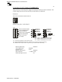
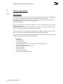
2.5
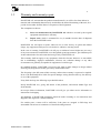
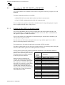
RS422 or RS485 Multidrop configuration
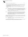
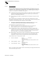
Up to 32 SYSTEM 9100 units can be connected in a RS422 or RS485 multidrop configuration.
It is also possible to run a Master/Slave configuration within a multidrop system. To set up the
Master/Slave configuration, see chapter 2.5.
Connect parallel cables to all masters at the port REMOTE.
Address all the masters so each unit has a unique address. See chapter 3.3.1 for setup
address in local and remote mode.
MPS no. Y
addresse : X+(Y-1)
+ OUT
- OUT
+ OUT
- OUT
+ OUT
- OUT
+ OUT
- OUT
REMOTE
Analog
16 POL
REMOTE
Analog
16 POL
REMOTE
Analog
16 POL
REMOTE
Analog
16 POL
X108
MPS no. 3
addresse : X+2
MPS no. 2
addresse : X+1
MPS no. 1
addresse : X
X :Start address
Y : The last unit of MPS on the
multdrop line
Example of multidrop configuration
About the termination of RS422 or RS45, see chapter 3.3.3 “Termination using RS422 or
RS485”
DANFYSIK A/S - DENMARK.
MAGNET POWER SUPPLY SYSTEM 9100
13
3
Operating instructions
This chapter outlines the procedure and precautions for the operation in local and in remote
control mode.
It identifies and describes the controls and indicators on the M-Panel Graphical.
Also the programming of the remote lines is described.
Instructions for initial remote line set up are given in chapter 3.3.
3.1
Switching on
When precautions have been checked in accordance with chapter 2.3 and 2.4, the power supply
can be switched on.
Immediately after the Power Supply is switched on, a start up screen appears on the M-Panel
and displays which control module is connected and makes a self test and scans for a text table
has been downloaded or not.
After approximately 5sec., the panel is ready for use. The remote line is ready for use after
approximately 3 sec.
Make sure that the time between switching the control power - OFF and - ON again is at least 5
sec. to ensure a correct cold start (initialization of the Power Supply).
- Select LOCAL CONTROL mode at the CMD-menu. "LOC" text appears in the display
(1).
To turn the power supply ON for the first time, it is recommended to activate it in the
LOCAL CONTROL mode as this is the easiest way to get started.
- If any Interlocks are set, push the "Reset" button (8).
Remove the faults if the Interlocks are not reset.
- Set the desired output current by use of the SET-menu.
- Switch the Main power "ON" (3).
- The READY LED (6) illuminates, when the output current is equal to the preset value
within a given accuracy typically +/-200ppm.
- Switch the main power "OFF" (5).
3.2
Operating with the Manual Control Panel
The MANUAL CONTROL PANEL (M-Panel Graphical) is an interface module that are used
with several Danfysik Magnet Power Supplies including SYSTEM 9100.
The SYSTEM 9100 comes with a M-panel as standard. It can however also be delivered with a
display board. This has two 5 digit 7 segment displays for voltage and current. LED indicators
for POWER ON, FAULT and READY. With this display board, the System 9100 can be
operated remotely from a PC, or by connecting an M-panel to the local port situated on the
back side of the system 9100. The M-panel can be connected and disconnected from the Power
Supply without affecting the power supply operation. Communication between the Power
Supply and the M-Panel is by a serial link, and may be physically located at the Power Supply
or up to 400 meters away from it.
DANFYSIK A/S - DENMARK.
MAGNET POWER SUPPLY SYSTEM 9100
14
3.2.1
Main power ON / OFF and interlock RESET
The basic function on the M-panel is to turn the power supply ON / OFF and to RESET
pending interlocks. All controlled from a single button. For further information about the
button locations, see chapter 3.2.3 Front Panel Control.
Setting the output current is done through one of the pull down menus described in the next
chapter.
When the power supply is ON the LED in the button area will illuminate.
When the power supply is OFF the LED in the button area will illuminate.
If an interlock is present the LED inside the RESET button will illuminate.
Pressing the RESET button will clear the interlocks that are not due anymore.
Hint: If an interlock is present, it will also be represented on the display at the lower right
corner.
Hint: The color of the LEDs can be reprogrammed to illuminate green, red or
“orange”.
3.2.2
Using the Manual Panel Menus
This chapter shortly describes the use of the M-Panel Graphical. The menus themselves will be
described later.
The user interface of the M-Panel Graphical is based upon pull down menus. To display the
menus simply press the MENU button (if not already standing in the Menu window).
To prevent unnecessary hiding of the main display (set current, output current and voltage) the
pull down menus are always displayed left aligned. In other words, it is the menu bar that rolls
over the pull down region.
With visible menu bar, activating the “” or “” arrow buttons the menu bar always displaying
the selected pull down menu at the left side will rotate. At the bottom right is a help text,
showing what the selected pull down menu group is used for. To select one of the lower menu
items the “” or “” arrow buttons must be used. Also here a help text at the bottom right of
the display will tell what the selected menu will do. If a menu has a sub menu it will be shown
with a right arrow to the right of the menu text. This sub menu can be accessed by pressing the
right “” arrow. Having found the desired menu it can be entered by pressing the “” Enter
key (The selected menu is shown inversed). If the chosen menu has a parameter to be edited a
pop up window will be shown with the parameter (as the set current menu), if the menu only
contains data to be shown a pop up window will be displayed with the data (as in the Interlock
menus) or if the menu is a command (as the REMote or the LOCal) then the task will be
executed immediately and the cursor will stay at its position. A pop up window is exited by
pressing the “” Enter key again.
The above in short, one can say: The menu bar is entered with the MENU key end exited again
with the MENU key (back to default window). A pop up window is entered with the “”
Enter key and exited again with the “” Enter key. Just like parentheses in equations.
DANFYSIK A/S - DENMARK.
MAGNET POWER SUPPLY SYSTEM 9100
15
As usual any rule has exceptions and these are:
- If there is no need for parameters after activating the “” button “Stand alone menu” there
is no need to press the “” button again. [One ” ” equals “( )” ]
- Pressing the MENU button while editing a parameter will abort the operation. [Regret the
operation as an “ESC”]
- Remotely changing the command status to Remote will automatically abort any local
operation.
Hint:
To ease the use, the “” Enter key may be used instead of one of the arrow keys in
some situations- i.e. if the action is given anyway. Eg. Standing on the top of a menu
the “” will do the same as the “” key or when standing in a menu containing a sub
menu the “” will do the same as the “” key. (Interferes a bit the mathematical
parentheses idea; but is fast to use in some cases)
Hint:
Pressing the MENU key the first displayed menu will either be the SET or the INTL
menu. The last one if at least one interlock is present. This minimizes the number of
buttons to be pressed to “MENU”, “” , “” for setting the output current or the
same key sequence to se the active internal interlocks. Actually the three lowest
vertical keys pressed from bottom up.
Changing a parameter is done with the arrow keys. (See also the help text at the bottom right of
the display). A cursor, shown as the digit inverse, marks the digit to be manipulated. Pressing
the “Enter” key ends the editing.
Hint:
Holding either the “” or the “” keys pressed when editing a number the auto
increment function will start.
If no menus have been used within 5 minutes, then the display will automatically be switched
back to the opening window aborting any current operation (security reason).
DANFYSIK A/S - DENMARK.
MAGNET POWER SUPPLY SYSTEM 9100
16
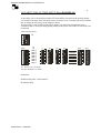
3.2.3
Front panel controls.
1. Graphic display 240*64
2. Main power is "ON" LED.
3. Main power "ON" push button.
4. Main power is "OFF" LED.
11
ME NU
3
10
ON
7. Control Power "ON". Back light is
lit.
OF
F
REA DY
4
6. READY LED indicates when the
actual
output current is within a predefined
limit.
5 6
12
5. Main power "OFF" push button.
8. Interlock "RESET" push button.
2
RES ET
7
10. MENU - Enter / Exit pull down
menus.
8
1
9
9. Sum Interlock LED.
11. Navigation keys.
12. ENTER - Enter / Exit parameter
change.
DANFYSIK A/S - DENMARK.
MAGNET POWER SUPPLY SYSTEM 9100
17
3.2.4
The Display
The display is a multi purpose graphic window to the user. The window can be divided into
three groups:
Default window:
The default window is shown below. If the Operator Control Panel is unused for 5 minutes, the
Operator Control Panel will automatically enter this state. This is for security reason. Escaping
from any menu back to this default window can be performed by pressing the “MENU” button
again. Any ongoing operation will be cancelled.
Scrolling menu bar
Power supply
Set and Output
Status
area
Pull down
menu area
Bar graph
Scrolling menu bar
The upper part of the display is normally used for displaying the viable top menus. In the
default window, “------ DANFYSIK ------“ will be displayed. It is called “scrolling menu
bar” because contrary to normal Windows © pull down menus it is the top menus that
scrolls with the “” “” buttons.
Pull down menu area
The pulls down menus are always shown in this area. If a pull down menu has sub menus
they will advance to the right. The second submenu will overwrite the “ Set and Output”
area.
Power supply Set and Output
Upper line displays the output current setting with six digits. After a cold start it displays
"SET 000000 ppm". When full output current is set, it displays "Iset 999999 ppm", which is
to be read as 99.9999 % of full scale. If required a setting in Ampere with six digits and a
decimal point can be adapted. This will be set at Danfysik during test or by Danfysik service
personnel.
The middle line display the actual output current with two digits. E.g. "Iout 54 %" means
that the current is 54 % of full scale. This reading is made by the internal 8 Bit bipolar ADC.
If a more accurate read out is required, the Control module can be added with a 16 Bit ADC.
The current will then be automatically displayed by six digits where the last digit always
will be zero. That is with five significant digits. E.g. "Iout 346340 ppm" means that the
current is 34.634 % of full scale. If required an output reading in Ampere with two or five
digits can be adapted. This will be set at Danfysik during test or by Danfysik service
personnel.
The lower line displays the actual output voltage with two digits. E.g. "Vout 45 %" means
that the current is 45 % of full scale. This reading is made by the internal 8 Bit bipolar ADC.
If required an output reading in Volt with two digits can be adapted. This will be set at
Danfysik during test or by Danfysik service personnel.
DANFYSIK A/S - DENMARK.
MAGNET POWER SUPPLY SYSTEM 9100
18
Bar Graph
The bar graph is an analog representation of the actual output current. The output current is
100 % when the bar-graph is full. The minor tics are for 5% steps and the major tics for 10%.
Each pixel represents therefore 0.5%.
Status area
The status area shows for a quick view the present control status of the power supply
These are:
- Control mode. LOCal or REMote Remote is shown inversed.
- Regulation status. ReaDY or not Ready is shown inversed and not ready as three bars.
- Main power. ON or OFF. OFF is shown inversed.
- The controlling address in a multi drop configuration. Blank if not enabled
Information area
The bottom right corner of the display is used for displaying other information. These are:
- The time taken from the SMD Control module is shown if nothing else is to be
displayed.
- INTERLOCK present if an interlock is pending. (In default window)
- STATUS present if a particular Status is pending, normally 1 transistor fault.
- Help text on the menus.
DANFYSIK A/S - DENMARK.
MAGNET POWER SUPPLY SYSTEM 9100
19
Menu Window:
Pressing the MENU button the
Menu window will appear. The
picture to the right shows the
opening window if no interlock is
present and after the “” button is
pressed once.
Editing Window:
If a value needs editing a cursor, shown as an inverted character, will occur somewhere in the
value. Somewhere because the cursor can remember its last used position. Move the cursor to
the desired position and change its
value with the “” or “” keys.
Holding the keys pressed will
initiate an auto increment /
decrement operation.
Pop Up Window:
The picture to the right shows a pop up window displaying many interlocks. The bar at the
bottom indicates that there is no further information downwards, and the arrow at the top
indicates that pressing the “”
button will display the above
listed interlocks. If a pop up
window contains values to be set,
the line to be changed will be
displayed inversed (cursor over
the line). Use the “” “” buttons
to change the value. “” & “”
scrolls between the lines. (Eg.
LED Color setup menu).
History Window:
The history window can be seen as
an oscilloscope screen with auto
scaling.
The picture to the right shows an
example history window set to
absolute scale with visible scale
units. The indicates one pixel unit.
DANFYSIK A/S - DENMARK.
MAGNET POWER SUPPLY SYSTEM 9100
20
3.2.5
Control Menus
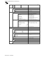
The table below lists the standard menus.
Scroll
menu
Sub menu 1
Sub menu 2
(Horizontal pop up layout)
Sub menu 3
SET
Comment
Setting of output current
CURRENT
Set output current immediately
CURRENT delayed
Set output current after
MEM
Memory function
RCL
Reg 0
9
Recalls one memory
STO
Reg 0
9
Stores to a memory
MAX/MIN
Set current to one end.
0%
Set current to zero
100%
Set current to max
CMD
Control Command line
REM
Set to Remote Control
LOC
Set to Local control
ADR
Select a multidrop address
INTL
Display Interlocks / Status
INT
Internal Interlocks
CROWBAR OFF
DC OVERCURRENT (OCP)
DC OVERVOLTAGE (OVP)
15VP OK
PHASE FAILURE
EARTH LEAKAGE FAILURE
FAN
MPS OVERTEMPERATURE
EXT
See also the list below the tables.
External interlocks
EXTERNAL INTERLOCK 0
EXTERNAL INTERLOCK 1
EXTERNAL INTERLOCK 2
EXTERNAL INTERLOCK 3
POL
DANFYSIK A/S - DENMARK.
Change output polarity
POS +
Set polarity to +
NEG -
Set polarity to -
+<>-
Invert output polarity
MAGNET POWER SUPPLY SYSTEM 9100
21
Scroll
menu
Sub
me
nu
1
Sub menu 2
Sub menu 3
Comment
LIMITS
Value limitations
I
SE
T
Current value limitations
POS
Positive limit
NEG
Negative limit
AD-CHAN
CHN 0-8
A/D Channels 0 to 8
Output current 3 significant digits
Hall-probe required.
Output Voltage 0 - 120%
Internal control voltage
Internal control voltage
Internal control voltage
Delta temperature inside regulated area
Output setting current
Output current 5 significant digits
Output current
Field Input
Vout
Internal +15V
Internal -15V
Internal +5V
Delta Temperature
I Set Value
Optional Iout 16 bit resolution
CHN 9-17
A/D Channels 9 to 18
Iout
Not Used
Output current for display
Output voltage for display
Not Used
Not Used
Used
Used
value
Output current for bar graph
Output current for display, in ampere
Output voltage for display, in voltage
Not
Not
Iset
Output setting current
DA-CHAN
Setting of D/A Channels
SETUP
Sets working conditions
BA
UD
CO
LO
UR
Operator Control Panel Baud rate setting
1200,
2400,
9600,
19200,
38400
57600
76800
115200
Communication may be lost when changing
the baud rate.
LED Color
Interlock
PSU ready
Power ON
Power OFF
Set to RED, GREEN or
“YELLOW”
SOUND
Buzzer ON or OFF
DEFAULT
Set to factory default
OP
TIO
N
ADR
Multidrop Address enable
HISTORY
OPEN LOG
DANFYSIK A/S - DENMARK.
Se chapter for further information.
MAGNET POWER SUPPLY SYSTEM 9100
22
3.2.6
Current setting
The output current may be set immediately as a potentiometer “SET CURRENT” or first preset
and thereafter accepted with the Enter ” ” button “SET CURRENT”.
Setting the output current choose the “SET CURRENT” menu, position the cursor above the
digit to alter and adjust the digit with the “” or “” button.
When the output current is within a predefined limit of the set value the "READY" LED will
turn ON.
It is also possible to set the output current to a predefined value, either using the storage
registers (STO, RCL in the MEM menu), to maximum current (=100% ) or to zero (=0%).
The maximum allowed set value can be limited through the LIMITS menu. This separates for
the positive and the negative set values. That is, if it is not possible to adjust the current above
a certain value, then check the limits.
The storage and the limit registers are saved within the M-Panel and can therefore not be used
in remote control. When using multidrop configuration e.g. all power supplies will share the
same limit.
3.2.7
Polarity reversal
If a polarity reversal switch is installed, a sign will be shown in front of the set value. (+ is
NOT reversed).
A polarity reversal procedure can be initiated either through the “POL” menu or simply by
putting the cursor above the sign in the “SET CURRENT” menu and changing the sign with
either the “” or “” button.
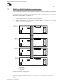
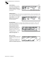
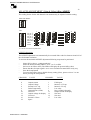
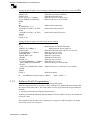
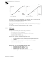
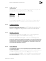
Please be aware that the system 9100 power supply is designed to work mainly in the first and
third quadrant, i.e. either positive output voltage and current or negative output voltage and
current. Working in the second or fourth quadrant is limited to the safe operating area of the
polarity switch transistors. The safe operating area of these transistors can be seen in the
picture on the next page. The Vds voltage on the horizontal axis is the drain to source voltage
of the transistors and is equal to the output voltage in the second and fourth quadrant. The Id
on the vertical axis is the drain current of the transistors. There are two transistors in parallel so
the actual allowed output current is equal to twice the drain current indicated on the graph.
The graph should be interpreted as follows:
If the output voltage of the 9100 during ramping down the current in an inductive load
becomes negative, say -10V, the current in one transistor must not exceed approx. 35 A i.e. the
output current must not exceed 70A.
The curves used in this example are the solid lines which should be used for DC operation.
The ramp time of the system 9100 bipolar version has been factory set to 3 sec., i.e. ramping
down from 150A to 0 takes 3 seconds, and from 0 to -150A also 3 seconds. Other ramp times
can be set by the user, see software manual for detailed description, but this must only be done
if the safe operating area is not exceeded. A lower ramp time i.e. ramping the current down
faster in an inductive load gives a higher negative voltage on the output (second quadrant
operation) and therefore the output current must be smaller so that the safe operating area is not
exceeded.
DANFYSIK A/S - DENMARK.
MAGNET POWER SUPPLY SYSTEM 9100
23
DANFYSIK A/S - DENMARK.
MAGNET POWER SUPPLY SYSTEM 9100
24
3.3
Operating by RS 232, RS422 or RS 485 I/O
The Control-Module uses standard serial interfaces compatible with many computers, PC and
terminals.
Two data communication lines are available:
- A REMOTE LINE, with either RS232, RS422 or RS485 communication.
- A LOCAL LINE, with either RS422 or RS 485 communication.
The two channels are galvanic isolated from all other internal voltages through opto couplers
but are supplied from the same voltage source.
3.3.1
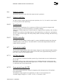
Setting up the MPS via display board
The set up of the MPS is done by two dip switches SW3 and SW4 together with the push
button S4 (SETUP), or through SW commands. Please refer to the “ESC” commands in the
SW appendix chapter for further information.
The two dip switches are configured as a multi function port, which will be validated by the
CPU upon pressing the button S4.
The four levers on SW3 instruct what parameters to set up, and the eight levers on SW4
delivers the actual parameters for this set up.
The parameters are first acknowledged after pressing the SETUP switch S4.
The SW3 switch position can also be seen as a binary number. The following table to the right
shows the SW3 number position and which parameters it controls.
Leaving all levers in the OFF position will disable the SETUP switch and enable Interlock
status mode. 8 LEDs will illuminate and
SW3
indicate which interlocks have occurred.
position
Parameter
Therefore please leave all dip switches
Number
in the OFF position as default.
0 {0000}
Interlock Status Mode
1 {0001}
REM_UART_SETUP
If the one of the set up modes are
2 {0010}
REM_LINE_SETUP
selected, the yellow LED D24 below
switch SW3 will illuminate and indicate
3 {0011}
REM_ADR_SETUP
that set up port is activated. The eight
4 {0100}
LOC_UART_SETUP
red LEDs, D13-D20 below switch SW4
5 {0101}
LOC_LINE_SETUP
will show the present parameter of
6 {0110}
LOC_ADR_SETUP
selected mode. Changing SW4 has no
7 {0111}
COLDBOOT_SETUP
effect, first after pressing S4 SETUP the
8 {1000}
AUX_SETUP
red LEDs (D13 to D20) will take the
9 {1001}
NOT USED
same indication as SW4.
10 {1010}
NOT USED
11 {1011}
NOT USED
12 {1100}
POLARITY_DELAY_PULSE
13 {1101}
NOT USED
14 {1110}
AD_AUTO_SCALE
15 {1111}
DA_AUTO_SCALE
DANFYSIK A/S - DENMARK.
MAGNET POWER SUPPLY SYSTEM 9100
25
Be aware when changing the Baud rates. Wrong setting may cause communication loss.
Modifying a baud rate with the HW switches or through the appropriate SW command, will
first take effect after a reset. At the remote line, use command ESC<CPURESET to make a
reset.
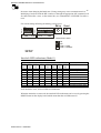
For switch settings following terminology will be used.
Setup
Reset
ON
1 2 3 4
SW 4
SW 3
ON
1 2 3 4 5 6 7 8
D24 - D30
D13 - D20
SIGNATURE USED:
ON
OFF
DON‟T CARE
DON‟T CHANGE
SETUP
Interlock LED indications (Mode 0)
LED
13
OFF
ON
LED
14
OFF
LED
15
OFF
red LED
LED LED
16
17
OFF OFF
LED
18
OFF
LED
19
OFF
LED
20
OFF
ON
ON
ON
ON
ON
ON
ON
Status
NO interlocks
Overvoltage
Overcurrent
Phase failure
Fault UV/Temp
Ground Leak
Fan
External interlock 1&2
External interlock 3&4
If all interlocks occur, all 8 red LEDs will illuminate.
When the interlocks are removed, the interlock LED indications can be reset by pressing the
RESET button on the display board which means that the red LEDs turn off.
DANFYSIK A/S - DENMARK.
MAGNET POWER SUPPLY SYSTEM 9100
26
UART HW SET UP (Esc<BAUD)
In the “UART HW SETUP” mode the baud rate and associated parameters for the serial lines
can be set.
SW3 indicates witch line to set up.
Hint: Selecting SW3 will immediately display the present setting on the red LEDs below SW4.
SW3 FOR LOCAL LINE
SW3 FOR REMOTE LINE
ON
3 4
1 2 3 4
ON
1 2
4
1
Parameters
SW4
1.200
2.400
9.600
19.200
ON
1 2 3 4 5 6 7 8
BAUD
RATE
PARITY
ODD/EVEN
7 / 8 Bits
STOP Bits
OFF
OFF
ODD
8 Bits
1½
ON
EVEN
7 Bits
2
Default setting after “COLD BOOT”
Local Line:
9600Baud, No party, 8 Bits, 2 Stop bits
Remote Line: 115200Baud, No party, 8 Bits, 1 Stop bits
DANFYSIK A/S - DENMARK.
38.400
57.600
76.800
115.200
MAGNET POWER SUPPLY SYSTEM 9100
27
ADDRESS LINE SET UP (Esc<ADR)
When using the RS422 or RS485 standard for the serial communication Remote or Local, it is
possible to attach a specific address to the line for multi drop connection.
The LOCAL line addressing can be used for controlling more power supplies through one
Operator Control Panel. (SW nr. 4 in the OPERATOR CONTROL PANEL must be ON).
Grounding problems has to be taken into consideration to avoid communication problems due
to noise and high differential voltages that may jam the input signals.
The REMOTE line addressing can be used for controlling more power supplies through one
serial line (one PC). Grounding problems has to be taken into consideration to avoid
communication problems due to noise and high differential voltages that may jam the input
signals.
SW3 FOR LOCAL LINE
SW3 FOR REMOTE LINE
ON
1 2 3 4
ON
1 2 3 4
6
3
Parameters
SW4
0
#1
1
2
3
ON
1 2 3 4 5 6 7 8
0
ADDR. 2
ADDR. 21
ADDR. 22
ADDR. 23
ADDR. 24
ADDR. 25
6
ADDR. 2
ADDR. 27
#1: Selecting address 0 or 255 equals allways addressed channel.
Default setting after “COLD BOOT”
Local Line:
Remote Line:
DANFYSIK A/S - DENMARK.
Address 0
Address 0
254
255 #1
MAGNET POWER SUPPLY SYSTEM 9100
28
LINE FUNCTION PROTOCOL SETUP (Esc<LINE)
SW3 FOR LOCAL LINE
ON
1 2 3 4
ON
1 2 3 4
5
SW3 FOR REMOTE LINE
2
The “LINE FUNCTION PROTOCOL SETUP” is for setting up serial line protocols.
Parameters:
SW4
ON
1 2 3 4 5 6 7 8
RS 485 COMMUNICATION
RS 485 LINE TURN AROUND
RS 485 LINE TURN AROUND
„OK‟ ANSWER MODE
BOOT CHARACTER
NOT USED
XON/XOFF PROTOCOL
NOT USED
DISABLED
DISABLED
DISABLED
DISABLED
SEND “FF” Hex
DISABLED
DISABLED
DISABLED
ENABLED
ENABLED
ENABLED
ENABLED
SEND “R”
ENABLED
ENABLED
ENABLED
Default setting after “COLD BOOT”
Remote Line: RS485 Communication:
Disabled
(=0)
RS485 Line turn around time:
Disabled Line turn around set bit 0
RS485 Line turn around time:
Disabled Line turn around set bit 1
OK Answer mode:
Disabled
BOOT character:
"FF" / "R"
NU
Disabled
XON/XOFF Protocol:
Disabled
NU
Disabled
Local Line: RS485 Communication:
Disabled
(=1)
RS485 Line turn around time:
Disabled Line turn around set bit 0
RS485 Line turn around time:
Disabled Line turn around set bit 1
OK Answer mode:
Disabled
BOOT character:
"FF" / "R"
NU
Disabled
XON/XOFF Protocol:
Disabled
NU
Disabled
Line turn around set bit:
2, 3:
0, 0
Delay = 0
2, 3:
1, 0
Delay = 1ms approx.
2, 3:
0, 1
Delay = 2ms approx.
2, 3:
1, 1
Delay = 3ms approx.
The line turn around time setting includes RS422 as well.
DANFYSIK A/S - DENMARK.
MAGNET POWER SUPPLY SYSTEM 9100
29
COLD BOOT SETUP (Esc<COLDBOOT)
After power up or reset the power supply can wake up in different control conditions. The
switch settings shown below describe the possible Wake up conditions.
Parameters:
SW3 FOR COLD BOOT INITIAL SETUP
ON
1 2 3 4
7
Default setting after “COLD BOOT”
SW4
ON
1 2 3 4 5 6 7 8
REMOTE ADDRESSING
LOCAL ADDRESSING
DEFAULT LINE IN
REMOTE AUTO ANSWER #1
ERROR RESPONSE
#2
Wake to 0%/100%
NOT USED
#3
ENABLED
ENABLED
REMOTE
DISABLED
DISABLED
DISABLED
LOCAL
ENABLED
¤1
¤2
0% at power up
¤3
¤3
100% at power up
¤1: “?”-BELL, Without further information.
¤2: “?”-BELL, Followed by error in code.
¤3: “?”-BELL, Followed by error in text.
#1: Local line is allways in auto answer mode.
#2: Using ACK/NACK protocol with or without error code will overide this setting.
#3: Default is 0% output current at power up. [From SW version SCS109]
Remote addressing:
Local addressing:
Default line in:
Remote Auto answer:
Error response:
Wake up output current:
DANFYSIK A/S - DENMARK.
Disabled
Disabled
Local
Disabled
“?”-BELL only
0%
MAGNET POWER SUPPLY SYSTEM 9100
30
AUX SETUP (Esc<AUX)
Special options can be initiated with the auxiliary switch set up 1.
Setting of bit 16 and 17 is intended for Offset DAC use. That is a 16 bit setting between 88 and
96% (Bit16=0 & BIT 17=1) or between 92% and 100% output current (Bit16=1 & BIT 17=1).
For linear DAC settings please set bit 16 & 17 to transparent mode.
Using the “WA” command a leading zeroes or trailing zeroes input format can be chosen.
- For leading zeroes: “WA 123" equals “WA 000123"
- For trailing zeroes: “WA 123" equals “WA 123000"
SW3 FOR AUXILIARY SETUP 1
ON
1 2 3 4
8
SW4
ON
1 2 3 4 5 6 7 8
DAC 16
DAC 17
INTERLOCK CLEAR
WA ZEROES
DISPLAY UNITS #1
CAMAC TEST
NOT USED
UNI/BI-POLAR
CLEAR
TRALING
A/V
DISABLE {Hi Z}
->0
->1
->1
->1
->0
->1
OFF & CLEAR
LEADING
%
ENABLE AS OUTPUT
UNIPOLAR
BIPOLAR
TRANSPARENT
#1 AD Scaling factor must be set accordingly.
Parameters:
Default setting after “COLD BOOT”
DAC 16 & 17:
Interlock clear:
“WA” Zeroes:
( ):
Transparent
OFF & CLEAR resets interlocks
WA command uses trailing zeroes.
UNIPOLAR
Notice that UNI/BI-polar is a read-only parameter and cannot be changed by dip switch setting
nor by software. The mode is detected automatically.
DANFYSIK A/S - DENMARK.
MAGNET POWER SUPPLY SYSTEM 9100
31
POLARITY DELAY TIME SETUP (Esc<POLDELAY)
A time delay can be inserted between the OFF state and the activation of the polarity change
over switch. The range of the time delay can be set from 0 to 25.5 seconds, (in steep of 100ms)
this for letting the rest energy in the magnet to decay.
The time delay is only inserted, if the power supply was ON before invoking the POL +/command. That is, when just changing the polarity in the power OFF mode, no time delay will
be inserted.
SW3 FOR POLDELAY
ON
1 2 3 4
12
#1
#2
SW4
0
ON
1 2 3 4 5 6 7 8
0
TIME 2
1
TIME 2
2
TIME 2
TIME 23
TIME 24
TIME 25
TIME 26
TIME 27
#1: Time is in 0.1 sec steps.
#2: Zero defaults to no delay
Parameters:
Default setting after “COLD BOOT”
No polarity delay.
DANFYSIK A/S - DENMARK.
0.1
0.2
0.3
25.4
25.5
MAGNET POWER SUPPLY SYSTEM 9100
32
AD AUTO ADJUSTMENT (Gain & Offset) (Esc<ADSET)
The scaling factors for the AD channels can automatically be adjusted with this setting.
SW3 FOR ADSET
ON
1 2 3 4
14
Parameters
SW4
0
1
3
2
30
31
#1
ON
1 2 3 4 5 6 7 8
0
CH_No. 2
CH_No. 21
2
CH_No. 2
3
CH_No. 2
4
CH_No. 2
NOT USED
FUNC
MODE
RESTORE
GAIN
USE
OFFSET
#1: Not all channels are implemented.
OFFSET adjustment
The OFFSET adjustment can automatically be executed if the value lies between 0 and 255 of
the AD channel resolution.
To activate the automatic OFFSET adjustment following steps must be preformed:
Select SW3 as above. “setting number14"
Select the desired channel number “lever 1 to 5" on SW4
Set lever 8 on SW4 to OFF (The LEDs will display the present Offset value)
Ensure that the AD input signal is set to zero. Grounded or turned OFF in any way.
Press the Setup Button
To restore the Offset value to default factory setting (Zero), please set lever 7 to one
before pressing the Setup Button.
-
CHANNEL
0
2
4
6
8
10
12
14
16
18
DANFYSIK A/S - DENMARK.
VALUE
CHANNEL
Output current
Output Voltage
Internal -15V sup.
Delta Temperature
Optional Iout (16 Bit)
Not used
Output voltage for display
Not used
Internal +5Vana.
Spare
1
3
5
7
9
11
13
15
17
VALUE
Field input
Internal +15V sup.
Internal +5V sup.
I set value
Iout (16 Bit)(Crtl panel).
Output current for display
Not used
Not used
I set value
MAGNET POWER SUPPLY SYSTEM 9100
33
GAIN adjustment
The GAIN adjustment can automatically adjust the scaling factor of the selected channel to
only nines. That is e.g. 99999 for the 16 bit output current reading. This adjustment is only
useful for the output current and voltage read back (CH0, CH2, CH8, CH11 and CH12) Please
do not use this feature if the output reading is in Volts and Amps and for not applicable
channels.
To auto adjust to a specific value, please use the “Esc”ADSET command.
To activate the automatic GAIN adjustment following steps must be preformed:
-
Select SW3 as above. “setting number14"
Select the desired channel number “lever 1 to 5" on SW4
Set lever 8 on SW4 to ON
Ensure that the AD input signal is set to 100%
Press the Setup Button
To restore the Gain value to default factory setting, please set lever 7 to one before
pressing the Setup Button.
DANFYSIK A/S - DENMARK.
MAGNET POWER SUPPLY SYSTEM 9100
34
DA AUTO ADJUSTMENT (Gain & Offset) (Esc<DASET)
The scaling factors for the DA channels can automatically be adjusted with this setting. This
feature is specially designed for “non calibrated”
SW3 FOR ADSET
ON
1 2 3 4
15
Parameters
SW4
0
1
2
3
30
31
#1
ON
1 2 3 4 5 6 7 8
0
CH_No. 2
1
CH_No. 2
CH_No. 22
3
CH_No. 2
4
CH_No. 2
NOT USED
FUNC
MODE
USE
OFFSET
RESTORE
GAIN
#1: Not all channels are implemented.
OFFSET adjustment.
The OFFSET adjustment can automatically be executed if the value lies between 0 and 255.
To activate the automatic OFFSET adjustment following steps must be preformed:
-
-
Select SW3 as above. “setting number15"
Select the desired channel number “leaver 1 to 5" on SW4
Set lever 8 on SW4 to OFF and leaver 7 to OFF (The SW1 LED‟s will display the
present Offset value)
Set the AD channel value (WA for “DA 0") to a value that gives a zero output.
Press the Setup Button. A given “DA 0 0" or “WA 0” will now produce a zero output at
the DA channel. Due to the unipolar operation of the DAC‟s only positive offset values
can be added.
To restore the Offset value to default factory setting (Zero), please set lever 7 to one
before pressing the Setup Button.
GAIN adjustment.
The GAIN adjustment can automatically adjust the scaling factor of the selected channel to
only nines. That is eg. 999999 for the WA command.
To auto adjust to a specific value, please use the “Esc”DASET command. (DAC setting in
Amps)
To activate the automatic GAIN adjustment following steps must be preformed:
-
Select SW3 as above. “setting number15"
Select the desired channel number “lever 1 to 5" on SW4
Set on SW4 lever 8 to ON and lever 7 to OFF.
Set the output signal to 100% with the DA or the WA command
Press the Setup Button.
To restore the Gain value to default factory setting, please set lever 7 to one before
DANFYSIK A/S - DENMARK.
MAGNET POWER SUPPLY SYSTEM 9100
35
pressing the Setup Button.
CHANNEL
0
1
2
3
4
Output current
Not used
Not used
Not used
Output voltage
DANFYSIK A/S - DENMARK.
VALUE
DA channel spec.
16 bit
WA range as default
16 bit
Equal to
MAGNET POWER SUPPLY SYSTEM 9100
36
3.3.2
Data communication
The SYSTEM 9100 uses the standard serial interface RS 232 which is compatible with many
computers and terminals. Beside RS232, SYSTEM 9100 supports RS422 and RS485.
The connectors for the serial interface ports “REMOTE CONTROL” and “LOCAL
CONTROL” are found at the back of the power supply.
Pin description for RS232 and RS422 for the connector DB25S at the back of the power supply
is as follow.
Pin No.
2
3
7
9
10
11
12
13
REMOTE CONTROL
DB25
RS422/RS485
RS232
Signal
Signal
TX
RX
RETURN
RETURN
TX_REM
/TX_REM
RX_REM
/RX_REM
Vcc
Vcc
LOCAL CONTROL
DB9
RS422/RS485
Pin No.
Signal
2
/TX_LOC
3
TX_LOC
4
/RX_LOC
5
RX_LOC
6-7
+15V
8-9
-15V
Rx : Signals received by the Control Module from its host.
Tx : Signals transmitted by the Control Module to its host.
NOTE! The selection between RS232, RS422 and RS485 is selected through solder straps on
the Control Board.
Serial interface
in REMOTE mode
RS232
2-Wire RS485
4-Wire RS422/RS485
Serial interface
in LOCAL mode
2-Wire RS485
4-Wire RS422/RS485
DANFYSIK A/S - DENMARK.
Strap
ST330 : Close
ST 324 : Open
ST 325 : Open
ST324 : Close
ST325 : Open
ST330 : Open
ST325 : Close
ST324 : Open
ST330 : Open
Strap
ST334 : Close
ST339 : Open
ST339 : Close
ST334 : Open
REMOTE CONTROL
DB25
Pin 2 TX
Pin 3 RX
Pin 9 TX_REM
Pin 11 RX_REM
Pin 9 TX_REM
Pin 10 /TX_REM
Pin 11 RX_REM
Pin 12 /RX_REM
LOCAL CONTROL
DB9
Pin 3 TX_REM
Pin 5 RX_REM
Pin 3 TX_REM
Pin 2 /TX_REM
Pin 5 RX_REM
Pin 4 /RX_REM
MAGNET POWER SUPPLY SYSTEM 9100
37
The default serial setting is:
8 BIT DATA, NO PARITY AND 1 STOPBIT and baud rate 115200.
The communication is done by transmitting characters in ASCII code terminated by
CARRIAGE RETURN.
The termination characters from the Power Supply are CARRIAGE RETURN and LINE
FEED.
An ERROR message includes a "?BELL". (Bell = ASCII 7.)
NOTE! None of the serial lines has control signals.
3.3.3
Termination using RS 422m or RS 485
As standard there is no termination resistors connected inside the M-panel. An external
termination resistor of 100 Ohm must therefore be added at the end of the communication
cable or the internal 100 Ohm resistor must be enabled (short-circuiting strap ST2). This
applies for both the local and the remote line.
The external resistor is preferable.
Hint. This resistor can be placed inside the last DB 25 plug for the remote line and the DB9
plug for the Local line.
When using the RS 485 or the RS 422 line in the multi drop configuration, it is very important
during an address transfer to leave the lines at the "SPACE" state when tri stated. That is when
the line is not driven by any transmitters at all. The "SPACE" state can be utilized by adding
1K Ohm resistors to +5 V(non inverting) and GND (inverting) on both the transmit and the
receive lines. The control module can provide this by short circuiting ST318-ST321 and
ST326-ST329 for the remote line and ST335-ST338 and ST340-ST343 for the local line (use a
thin soldering iron). The 1K resistors increase the noise immunity eliminating noise to be
treated as commands thereby flawing the first character after being addressed.
NOTE!
None of the two serial lines have control signals (hand checking). Use the
XON/XOFF protocol if necessary.
DANFYSIK A/S - DENMARK.
MAGNET POWER SUPPLY SYSTEM 9100
38
3.3.4
Programming
The power supply communication protocol is built upon plain ASCII characters where each
command or reply is delimited by a "Carriage Return" <CR> character. However replies have
a “Line Feed” <LF> character added before the <CR> for a friendlier display when using a
terminal. <LF> characters on commands will be ignored.
Hint. Actually the protocol allows full control of the power supply from a "dumb" terminal. In
case of a service- debug- situation a terminal can be used to tap the communication
transfer by a simple parallel connection.
Hint: When debugging, the "ERRT" command enables error messages to be given as a read
able text.
More commands may be transmitted in a chain but each single command must be trailed
individually with the delimiter character <CR>. The power supply is able to execute up to 200
commands a second depending of the complexity of each command.
Ps.
Issuing short commands faster than the time to transmit the answer e.g. “S1" will
overload the internal transmit buffer regardless of the selected baud rate.
All commands can be divided into three sections.
a)
Directive commands. Eg. the "N" command that turns the power supply ON
b)
Status commands. Eg. the "S1" that returns the power supply status
Status commands delivers always a reply whereas directive- and setup- commands only
responds with an error message if the command couldn‟t be understood or if the given
parameters are incorrect. It is possible to set the power supply to always generate an
answer; this feature is very useful when using RS485 protocol.
Hint. When using the "Always Answer" mode a re-transmission of the last given command
can be performed if no answer or an error message is received. The System 9100
respond time is around 5ms after receiving the last bit of the termination character.
Answer scheme if set to “Always Answer” mode.
c)
Directive commands.
d)
Status commands . Answer:
e)
Set up commands. Answer:
Answer:
- No answer
- ERROR message
- OK if set to always answer mode (ab SW ver. SCY
2.xx)
- Data
- ERROR message
- No answer
- ERROR message
- OK if set to always answer mode (ab SW ver. SCY
2.xx)
Below is an example written in BASIC on how to turn ON the power supply and read the status
without and with acceptance answer:
DANFYSIK A/S - DENMARK.
MAGNET POWER SUPPLY SYSTEM 9100
39
Turning the power supply ON and reading/evaluating the status with always answer disabled.
LPRINT "N"+CHR$(13)
:REM Turns the power supply on
LPRINT "S1"
:REM Issues the status command
LINPUT S1$
:REM Read the MPS reply
IF LEFT$(S1$,1) = CHR$(?)
:REM Is it an error message reply?
GOTO ERROR_HANDLING
:REM Yes then go to error module
ENDIF
J=1
DO
:REM evaluate status reply
IF MID$(S1$,J,1)="!"
GOSUB STATUS(J)_ACTIVE
:REM set this status bit active
ELSE
GOSUB STATUS(J)_ACTIVE
:REM set this status bit inactive
ENDIF
J=J+1
UNTIL J=24
Turning the power supply ON with always answer enabled
J=0 :ERROR$=”“
DO
J=J+1
:REM Counter for maximum attempts
LPRINT "N"+CHR$(13)
:REM Turns the power supply on
LINPUT RE$
:REM Read the MPS reply with 0.1 Sec. time out
IF LEFT$(RE$,1) = CHR$(?)
:REM Is it an error reply?
ERROR$=RE$
:REM Mark the error code
ELSEIF RE$=”OK”
:REM Is it a good reply
BRAKE
:REM then exit DO loop
ELSEIF J=6
:REM Try only six times
IF LEFT$(ERROR$,1) = CHR$(?) :REM Was it error reply?
GOTO ERROR_HANDLING
:REM Yes then go to error module
ELSEIF
GOTO NO_COMMUNICATION :REM Yes then go to “No answer” error module
ENDIF
ENDIF
UNTIL -1
:REM loop endless
Ps.
3.3.5
An ERROR message includes a "?BELL".
(Bell = ASCII 7.)
Software Profile Programming
SYSTEM 9100 is delivered with the software ramp profile option.
With the ramp profile SW it is possible to down load and run a predefined ramp sequence that
the output current must follow. The ramp sequence can be programmed in two quite different
methods.
A- Arbitrary point method; B- Equal timeslot method.
Arbitrary point method and Equal timeslot method are both available, but only one method can
be used at a time.
The examples below are shown for a unipolar power supply. For bipolar supplies, the output
current may also be set as negative.
DANFYSIK A/S - DENMARK.
MAGNET POWER SUPPLY SYSTEM 9100
40
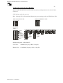
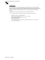
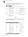
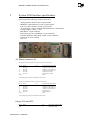
3.3.6
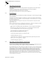
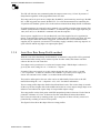
Arbitrary point ramp profile method
With the ”Arbitrary point method” it is possible to download up to fifteen independent points
each generating a ramp line (through interpolation). This profile must be stored in one of the
15 available stacks.
Each ramp point consists of a stack number, a starting point (current set value, normally the
previous end point), an end point (current set value) and a time value for reaching the given
end point.
E.g. Command:
WSA' sp' stack, start, stop, time 'cr'
To use the arbitrary point method at least the following steps must be preformed:
- Clear the stack “CSS [parameter]”,- Program the stack “WSA [parameter]”,- Set the speed
“SPEED [parameter]”, -Set the attenuator “MULT [parameter]”, -Start the stack “TS
[parameter]”, -Read the status of the running stack “S2".
Please refer to the software manual about “SW2 Ramp Profile Commands” for full
instructions.
The figure shows an example of one ramp profile stack. (Ps. not all 15 points need to be
programmed empty, entries will be ignored.)
Software Ramp Profile
Arbitrary Point Method
Output
Current
No5
No7
No6
No4
No3
No1
No2
Relative
T1
T2
T3
T4
T5
T6
T7
Time
From
TRIG
The SW will after the start (Trig) command update the output current every 1.25ms in the
FAST and in the SLOW mode (Step Time). This enables us to calculate the stair case size
(interpolating step size) according to the formulae below:
Where “START” and “END” are the set values in ppm. The “Step Time” is 1.25ms. , Δt in
seconds and the “Step. Size” will come out as ppm value.
In-between the 1.25ms step time a second HW interpolation counter will update the set value
for every 78μs (fast ramp times) to about 78μs (slow ramp times).
Starting the ramp is done with the trig command “TS (stack no.)”.
DANFYSIK A/S - DENMARK.
MAGNET POWER SUPPLY SYSTEM 9100
41
If synchronization to an eternal event is required, it is possible to arm the ramp sequence first
with the synchronization command “SYNC (stack no.), [trigger delay]”. A hardware signal on
the trigger input X9 pin 1&2 (10 to 24V) or a TS command will start the sequence. If a trig
delay is entered, the sequence will first start after the delay time has elapsed.
If more power supplies have to be synchronized, one of the supplies has to be appointed as
master. Connecting the master trig output X9 pin 3&4 to the other supplies trig input will start
the other supplies when the master is triggered. A maximum skew of 5μs between the supplies
may be expected. (an external 15V auxiliary supply is needed, as the trig output is an open
collector and the trig input is an optocoupler input.)
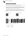
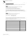
3.3.7
Equal time slot ramp profile method
With the ”Equal time slot method” it is possible to download up to 1000 current set values and
a single time slot value, that will be used for all set values. Only one stack is available.
This profile method is especially useable for faster and more accurate curves fitting profiles
e.g. as a function generator.
To use the Equal time slot method at least the following steps must be preformed:
- Clear and set the stack “RAMPSET [parameter]”,- Program the stack “R [parameter]”, -Start
the stack “RAMP [parameter]”, -Read the status of the running stack “RAMP".
PS.
A difference in the value parameters setting comparing to the “Arbitrary point method”
is, that all values must be given as a floating point number scaled to “1.000000". That is;
1.25ms must be entered as 0.00125 and 19.54% output current as 0.1954.
Please refer to the Software manual about Ramp Profile Commands for full instructions.
The figure below shows an example of one ramp profile stack. (Ps. not all 1000 points need to
be programmed empty entries will be ignored.)
Software Ramp Profile
Equal Time Slot Method
Output
Current
15
20
10
Incremental
2
5
3 4
1
25
26 27
Time
From
TRIG
Time Slots
The time slot
must be given as a multiple of 1.25ms. Between 1.25ms to 1 second. Any value in-between
will automatically be rounded according to formula:
{time slot}=frac({time}/0.00125)*0.00125
DANFYSIK A/S - DENMARK.
MAGNET POWER SUPPLY SYSTEM 9100
42
The SW will after the start command update the output current every 1.25ms. By means of
interpolation regardless of the programmed time slot value:
The ramp can be set up to run as a single shot “RAMP R”, auto iteratively (auto loop) “RAMP
RL” or HW triggered auto armed “RAMP TW”. For a full documentation on controlling the
“Equal time slot method” please refers to the software manual about Ramp Profile Commands.
If synchronization to an external event is required, it is possible to arm the ramp sequence first
with the synchronization command “RAMP T”. A hardware signal on the trigger input X9 pin
1&2 (10 to 24V) or a “RAMP R” command will start the sequence.
If more power supplies have to be synchronized, one of the supplies has to be appointed as
master. Connecting the master trig output X9 pin 3&4 to the other supplies trig input will start
the other supplies when the master is triggered. A maximum skew of 1.25ms between the
supplies may be expected. (an external 15V auxiliary supply is needed, as the trig output is an
open collector and the trig input is an optocoupler input.)
3.3.8
Auto Slew Rate Ramp Profile method.
With the”Auto Slew Rate Ramp Profile Method” an automatic ramp profile will be generated
and executed when issuing a new current set point. In other words, this feature acts like a
software driven slew rate controller.
Two shapes can be preselected. A cosines and a square shape. Which shape is selected, is
given by the Aux2 setting bit 4. 0 = Cosines & 1 = Square
Example: If the power supply is at 10% output current, the slew rate is set to 1 second
(„esc‟<slopetime 1.1) and a set command “da 0.600000" is given the power supply will
start at 10% and run to 60% within ½ a second with the selected shape.
The positive and negative slew rate value can be set individually. Please refer to the SW
manual describing the “„esc‟< slopetime „val1',‟val2'” for further information.
The two ramp profile shapes has both its benefit and draw backs. The cosines shape is smooth
all the way but has a higher di/dt in the middle and results in a sinus output voltage shape on an
inductive load whereas the square shape in a trapezoidal output voltage
The ramp profile consist of 80 points with HW interpolated points in-between. Each of the 80
points has a distance of 2.5 ms. In-between. Profiles with shorter distances than 200ms
(80*2.5ms) are achieved by omitting points. Eg. a ramp time of 20ms will only consist of 8
points thereby resulting in a more coarse profile.
The figures below shows the shape of the two ramp profiles.
DANFYSIK A/S - DENMARK.
MAGNET POWER SUPPLY SYSTEM 9100
43
The time slot must be given as a multiple of 1.25ms. Between 1.25ms to 1 second. Any value
in-between will automatically be rounded according to formulae:
{time slot}=frac({time}/0.00125)*0.00125
The ramp profile can be stopped either with a “STOP” command or when the power supply is
turned OFF.
The state of the ramp profile can be read through the “RR” command.
3.3.9
SW limits
The limits of the “Arbitrary point method” ramp profile SW are:
-
The set value must be given in ppm units
The time between two points can be between 0.2 to 65535 seconds.
Maximum numbers of stacks: = 15
Maximum number of lines in a stack: = 15
The limits of the “Equal time slot method” ramp profile SW are:
-
The set value must be given in a floating point representation normalized to
1.000000.
The time slot may be between 0.0125 to 1 second given in a floating point
representation normalized to 1.0000.
Maximum numbers of stacks = 1
Maximum number of time slots in a stack = 1000
The limits of the “Auto Slew Rate method” ramp profile SW are:
Maximum positive slew rate time = 10 sec,
Maximum negative slew rate time = 10 sec,
Minimum positive slew rate time = 5m sec,
Minimum negative slew rate time = 5m sec,
Number of points = 80 with a minimum interval of 2.5ms
DANFYSIK A/S - DENMARK.
MAGNET POWER SUPPLY SYSTEM 9100
44
SW Commands
Following are the commands for the standard software listed in alphabetic order.
Please see the SW appendix 1 for detail explanation of every command.
STANDARD COMMANDS. Summary
AD X
Read value from an ADC
channel.
Read the address of the MPS.
Write an address to a MPS.
RA
Read the set value.
REM
RLOCK
Change to remote control.
Remote line only
ANACTRL
ASW
MPS Control by analog Set.
RR
RS
Read Ramp speed.
Enters Answer mode
CMD
CMDSTATE
CPUCTRL
Read current control mode.
Read current control state.
S1
S1H
Read the internal status.
Read internal status in HEX
format
S1FIRST
S1FIRSTH
in HEX format
Read the interlock first catch status.
Read the interlock first catch status
S3
Read the internal extended
status.
Read internal extended status in
HEX format
ADR
ADR XXX
MPS Control by CPU DAC.
DA X,XXXXXX
Writes a value to an Digital
to Analog converter.
(Alternative to the WA
command.)
ERRC
ERRT
Coded error message.
Text string error message.
F
Main Power OFF
LALL
LOC
LOCK
Listen ALL.
Change to Local Control
Lock the MPS in Local Control.
N
NASW
NERR
Main Power ON
PO
PO +/POLOOL
PRINT
Polarity status
Change to Normal polarity
No answer mode.
S3H
Reset interlocks.
TD
Test DAC
TYPE
AD type in use
UNLOCK
Unlock the MPS
VER
Reads the software version
No error message
Polarity Output Off Limit.
WA XXXXXX Writes a value to a Digital to
Analog converter.
(Preferred new command:DA 0)
Reads internal user information
about the MPS.
WR
Write Ramp speed
X is a number from 0 to 9 and Commands in quotation marks are optional
DANFYSIK A/S - DENMARK.
MAGNET POWER SUPPLY SYSTEM 9100
45
Following are the SET UP commands for the standard software listed in alphabetic order.
Please be aware that some of these commands should only be used with caution.
See the SW appendix for detail explanation on every command.
„esc‟ SET UP COMMANDS. Summary
ESC<AD
Configures the AD converter
attaining and routing (Output reading adjustment or output reading in
% or Amps)
ESC<ADR
Configures the communication
address setting (in RS422
mode).
ESC<ADSET
Auto Configures the scaling
“gain” and Offset for an AD
converter channel.
ESC<AUX
Configures the special options
ESC<BAUD
Configures the Baud rate for the
serial lines.
ESC<COLDBOOT
Configures the power up state
(Wake up position)
ESC<CPURESET
Hardware reset / CPU reset
ESC<DA
Configures the Digital to Analog
converters. (Slew rate setting in
A/sec or set value in Amps)
ESC<DASET
Auto Configures the scaling
(gain) and Offset for a DA
converter channel.
ESC<LINE
Configures the protocol for the
serial lines.
ESC<POLDELAY
Configures the delay between
off and polarity switch change
(
P in alphabetic
Following are the commands for the software driven “RAMP PROFILE” listed
r
order. Please see the SW manual for parameter formats and further detail description.
e
These commands are optionally available.
f
e
r
SW RAMP PROFILE COMMANDS “Arbitrary point method”. Summary r
e
CONT
Continue sequence operation
RWSP XX
Reset writedpointer
CSS
Clear sequence stack and pointers.
FAST
Fast sequence timing
HALT
Halt sequence operation
MULT
Reads the multiplying factor
for the DAC scaling
MULT X
Writes a multiplying factor for
the DAC scaling
RRSP
Reset read sequence pointer
S2
Read sequence
n status
SLOW
Slow sequence
w timing
SPEED
Read sequence
c timing
STOP
Stop sequence executing
e
SYNC
TS
WSA
RSA
RSP
DA 0)
Read sequence and auto
increment
Read sequence position
o
m
m of sequence
Synchronization
a
n
Trig sequence
d
Write sequence
: and auto
increment
WSP
Write Sequence position
SW RAMP PROFILE COMMANDS “Equal Time slot method”. Summary
DANFYSIK A/S - DENMARK.
(
P
r
MAGNET POWER SUPPLY SYSTEM 9100
46
R
Write data to the stack.
RAMPSET Time,Multiplicant, [LWN],C
Configure the ramp operation
RAMP [RSHTN],[LWB]
Control the stack operation
(
P
r
e
f
e
r
r
e
d
n
e
w
c
o
m
m
a
n
d
:
DA 0)
DANFYSIK A/S - DENMARK.
MAGNET POWER SUPPLY SYSTEM 9100
47
3.4
Operating in analog mode
The SYSTEM 9100 can operate in analog mode and can be set either by software or hardware
via jumpers.
Software:
For enabling analog mode by software no jumpers must be set on J502 and J503.
The jumpers are located on control module PCB 91376.
The software command ANACTRL puts the MPS in analog mode.
Likewise, the command CPUCTRL sets the MPS in CPU control mode.
The ANACTRL command switches the I Set Value between analog control and I Set Value
from CPU control board DAC. ANACTRL change the I Set Value into analog control.
For more information about the command ANACTRL, refer to software manual for SYSTEM
9100.
Hardware:
For enabling analog mode by hardware some jumpers need to be set.
The jumpers are located on control module PCB 91376
Jumper configuration:
J502 in position 1 and 2
J503 in position 1 and 2
In order for controlling and monitoring the different analog modes, several pins are available
for these uses. The connector X108, back on the MPS, is dedicated for analog controlling and
monitoring. For detail pin description, see chapter 4.1.2.
The table below shows the analog modes and the pins for a specific mode.
Analog mode
Connector X108
Analog I set point: 0-10 V
pin 16 and pin 23
Analog I monitoring: 0-10 V
pin 7 and pin 25
Analog I set point read back 0-10V
pin 10 and pin 25
Analog V set point: 0-10 V
pin 15 and pin 20
Analog V monitoring: 0-10 V
pin 19 and pin 24
Analog V set point read back: 0-10 V
pin 9 and pin 24
ON/OFF control 12 V galvanic isolated
pin 14 and pin 2
DANFYSIK A/S - DENMARK.
MAGNET POWER SUPPLY SYSTEM 9100
48
3.4.1
Standard interface / Parallel interface
The analog mode can be set up to operate in two different modes, standard or parallel. Default
mode is standard.
Table below shows input/output connections of the two modes and straps settings for selecting
standard or parallel mode. Notice that you need to cut some straps and likewise to solder some
straps for changing to parallel mode. The straps are located near the D-SUB25 on bottom side
of the PCB.
D-Sub 25
X108
(backplane)
1
2
3
Standard Mode
Straps
(standard)
Parallel Mode
Straps
(parallel)
Spare
ISO RTN
Spare
-
ST801=close
ST803=close
4
Spare
-
5
ON
6
COM
(GNDD)
I-MON
ST817=close
ST805=open
ST818=close
ST806=open
ST819=close
ST807=open
ST821=close
ST809=open
ST823=close
ST811=open
ST825=close
ST813=open
ST815=close
ST802=open
-
Sum Interlock *
ISO RTN
ON/OFF status,
low=ON *
/Ready status
Low=Ready *
Sum Ext interlock
*
Earth leak status
7
8
9
RTN AUX
(GNDA)
V-set Readback
10
I-set Readback
11
12
13
14
15
I-set Parallel
V-set serial
GNDA
ISO TTL/CMOS
VP 10V
16
IP 10V
17
18
19
20
Fault relay
Fault relay
V-MON
VP RTN
21
+15V AUX
22
-15V AUX
23
IP RTN
24
V-MON RTN
25
I-MON RTN
* Open Collector output
DANFYSIK A/S - DENMARK.
ST820=close
ST808=open
ST822=close
ST819=open
ST824=close
ST812=open
-
-
Overcurrent status
GND
(Parallel)
/OFF control
RESET control
I-set Parallel
V-set serial
GNDA
ISO TTL/CMOS
LOC/REM status
Low=LOC *
SOLL-WERT &
SOLL-WERT
sense
Fault relay
Fault relay
V-MON
Phase fail status *
GND
(parallel)
ON control
SOLL-WERT
GND & SOLLWERT sense GND
V-MON RTN
I-MON RTN
ST804=close
ST817=open
ST805=close
ST818=open
ST806=close
ST819=open
ST807=close
ST821=open
ST809=close
ST823=open
ST811=close
ST825=open
ST813=close
ST815=open
ST802=close
-
ST820=open
ST808=close
ST822=open
ST819=close
ST824=close
ST812=open
-
-
MAGNET POWER SUPPLY SYSTEM 9100
49
4
Theory of operations
4.1
Introduction
The following chapter describes in short the main components/blocks of the SYSTEM 9100.
An overview of the SYSTEM 9100 architecture can be found on next page.
Furthermore an interface specification i.e. an overview of the possible connections will be
listed with description of every single pin and its use.
Technical description
The power supply modular system is mounted in a 19” rack. The dimension of the rack is 3U
high and 600mm deep.
This allows for quick replacement of all modules and print circuit boards in Magnet Power
Supply. Thus this reduces service-time and total down time.
The System 9100 is a full bridge phase modulated, zero voltage-switching converter, which
offers several benefits compared with traditional hard-switching technology.
Figures below are block diagrams of the SYSTEM 9100 unipolar and bipolar type. There are
11 blocks and each block will be described in short.
-EMI filter.
-Diode module
-Soft start module
-AC input filter module.
-Output modules (1 to 4 modules depending of max output current)
-Aux power supply, PCB.
-I-loop, CPU control, interlock, PCB.
-DCCT transducer.
-Display module.
-Local control M-panel.
-Bipolar output stage (Bipolar only)
DANFYSIK A/S - DENMARK.
OPTIONAL
3.3V
5V
X5
Optional X6
For local M-panel
X7
POLARITY
X8
TRIG
X9
Ext. intl
X12
Vout
Iout
Iset
Iset
Vset
ON
/OFF
RES
REMOTE RS232/RS422
D-SUB 25
Inverter
Ethernet
controller
ETHERNET Module
X108
PARALLEL INTERFACE
Optional SPI
Interface
CONTROL POWER
INPUT
X1
1PHASE
5V to 3.3V
supply
CONN.
D-SUB 25
CONN.
CONN. CONN.
D-SUB 25
±15VDC_C
/1,2A
X413
J101
0-10V
±15V
OPTO
+5V
Ext/Int SPI
interface
Select & Detect
ATmega
128
OPTO
POLARITY
SWITCH
TRIG
IN/OUT
BUFFER
Optional
SERIAL
SPI
INTERFACE
2
±15V
+5V
RAM
I/O SPI PORT
INTERLOCK &
ON/OFF CONTROL
+12V
/0.1A
FAN CONTROL
AUX POWER
I >
OVERCURRENT
BREAKER
(FRONT
OPPERATED)
+24VDC_S
/1,6A
AC LINE
MONITOR
(AC OK)
1
I-LOOP, CONTROL, INTERLOCK PCB
±12VDC_C
/0,1A
LOOP & CPU
AUX POWER
AUX POWER PCB
CONN.
CONN.
MAIN POWER
INPUT
3PHASE
X1
10 BIT
A/D
DANFYSIK A/S - DENMARK.
D-SUB 9
AC INPUT FILTER
U
V
W
ISOLATION
SMPS
GALVANIC
ISOLATED
AUX POWER
ROM
16 BIT A/D
Differential
Input
(Io, Vo, Iset)
Peltier
Control
Overcurrent, Ground leak
Module Fail, OPTO
Over Temperature, OPTO
Output Voltage
X414
SOFT START
MODULE
AUX POWER
FOR DC/DC
PRIMARY SIDE
-
+
Output Current
RECTIFIER
3PHASE
±15VDC_C
EMC
FILTER
J101
DC
KEYBOARD
LCD DISPLAY
240x64 DOT
DC/DC
PSU
H8 uP
SYNC B 180°
M-PANEL
16 BIT D/A
V set
19 BIT D/A
Uni & BiPo, I set
SYNC
PWM
SYNC
SYNC A 0°
NO. 2 to 4
DC/DC SMPS
OUTPUT MODULE
ENABLE
I-SET
PWM
±15VDC_C
NO. 1
DC/DC SMPS
DIFFERENTIAL
AMPLIFIER
I SET OPTO
0-10V
REF.
A/D
D/A
STATUS/CONTROL
OPTO
-5V
/0.1A
+15VDC_P
/2A
FILTER
+15VDC_P
SLEW
RATE
LIMIT
Io
+24VDC_S
REGULATION
I LOOP
V LOOP
ON
/OFF
SUM_INTL
Vo
DIFFERENTIAL
AMPLIFIER
FANS
SOFT START
CONN.
Relay Interface
X414
10VDC
125A
X25
X24
CONN.
SCREW
TERMINAL
MAGNET POWER SUPPLY SYSTEM 9100
50
Unipolar block diagram:
Vout
DCCT I HEAD
+5VDC_C
3.3V
5V
TRIG
X9
Ext. intl
X12
Vout
Iout
Optional X6
For local M-Panel
REMOTE RS232/RS422
X7
D-SUB 25
Inverter
Ethernet
controller
ETHERNET Module
Iset
Iset
Vset
ON
/OFF
RES
X5
POLARITY
X8
PARALLEL INTERFACE
X108
OPTIONAL
X1
CONTROL POWER
INPUT
X1
1PHASE
5V to 3.3V
supply
CONN.
D-SUB 25
CONN.
CONN. CONN.
J101
±15VDC_C
/1,2A
0-10V
OPTO
±15V
Ext/Int SPI
interface
Select & Detect
ATmega
128
OPTO
POLARITY
SWITCH
TRIG
IN/OUT
BUFFER
Optional
SERIAL
SPI
INTERFACE
2
±15V
+5V
RAM
I/O SPI PORT
Uni/Bipolar
Mode
INTERLOCK &
ON/OFF CONTROL
+12V
/0.1A
FAN CONTROL
AUX POWER
I >
OVERCURRENT
BREAKER
(FRONT
OPPERATED)
+24VDC_S
/1,6A
AC LINE
MONITOR
(AC OK)
1
I-LOOP, CONTROL, INTERLOCK PCB
±12VDC_C
/0,1A
LOOP & CPU
AUX POWER
AUX POWER PCB
CONN.
CONN.
MAIN POWER
INPUT
3PHASE
10 BIT
A/D
DANFYSIK A/S - DENMARK.
D-SUB 25
U
V
W
ISOLATION
SMPS
GALVANIC
ISOLATED
AUX POWER
ROM
16 BIT A/D
Differential
Input
(Io, Vo, Iset)
Peltier
Control
Overcurrent, Ground leak
Module Fail, OPTO
Over Temperature, OPTO
Output Voltage
X414
SOFT START
MODULE
AUX POWER
FOR DC/DC
PRIMARY SIDE
-
+
Output Current
RECTIFIER
3PHASE
DC
J101
SYNC B 180°
KEYBOARD
DC/DC
PSU
H8 uP
LOCAL M-PANEL
LCD DISPLAY
240x64 DOT
OPTION
16 BIT D/A
V set
19 BIT D/A
Uni & BiPo, I set
SYNC
PWM
SYNC
SYNC A 0°
NO. 2 to 3
DC/DC SMPS
OUTPUT MODULE
ENABLE
I-SET
PWM
±15VDC_C
NO. 1
DC/DC SMPS
DIFFERENTIAL
AMPLIFIER
I SET OPTO
0-10V
REF.
A/D
D/A
STATUS/CONTROL
OPTO
-5V
/0.1A
+15VDC_P
/2A
FILTER
+15VDC_P
SLEW
RATE
LIMIT
REGULATION
I LOOP
V LOOP
ON
/OFF
SUM_INTL
BIPOLAR
OUTPUT
STAGE
Io
Vo
DIFFERENTIAL
AMPLIFIER
+24VDC_S
SOFT START
CONN.
Relay Interface
X414
FANS
DCCT I HEAD
D-SUB 9
AC INPUT FILTER
±15VDC_C
EMC
FILTER
10VDC
125A
X24
CONN.
SCREW
TERMINAL
X25
MAGNET POWER SUPPLY SYSTEM 9100
51
Bipolar block diagram:
Vout
+5VDC_C
MAGNET POWER SUPPLY SYSTEM 9100
52
4.2
M-Panel
The M-panel is the user interface for reading current, voltage, status and making settings to the
MPS. The display has a resolution of 240*64.
The display board is built upon a micro-processor IC2, which communicate to the control
module via RS422 interface.
4.3
I-Loop, Control, Interlock PCB
The control board contains DAC for the set value, ADC for the read back, Peltier control,
DC/DC converter, serial interface, loop control, interlock and the controlling micro-processor
with external memory.
4.3.1
Micro-processor
The micro-processor is the intelligent part of the system. It consists of the micro-processor
U212, a CPLD U213, external static memory (SRAM) U214 and 3-8 decoder U211.
The micro-processor is of the type ATMEGA128 from Atmel and the CPLD is an AFT1502
from Atmel.
The CPU runs at 14.7456 MHz, controlled from the crystal Y202.
The micro-processor has built-in "Watchdog" circuit and will reset the CPU, if it for some
reason stops refreshing the watchdog.
As memory it uses its internal FLASH EEPROM for bootstrap loader and U214 with 1Mbit
capacity for the PGM storage. The PLD chip U213 generates the lower address lines as well as
the chip select signal for the SRAM. U211 74HCT138 3-8 decoder provides chip select signal
for DAC, ADC, interlocks, external status and display board.
4.3.2
DAC Circuit
The DAC circuit converts the serial digital set value to a voltage reference.
The circuit is built around U701, U702 and U705. U701 and U702 is connected to perform a
20 bit DAC used for setting the current, 19 bit plus sign while U705 is used for setting the
output voltage in the voltage mode.
The DAC circuit delivers an output voltage proportional to the digital input value.
The Digital to Analogue Converter sets the output current level in local/remote mode.
DANFYSIK A/S - DENMARK.
MAGNET POWER SUPPLY SYSTEM 9100
53
4.3.3
ADC Control
Different voltages are monitored by means of the Analogue to Digital converter U706. The
measured values and their resolution are shown in the table below.
The 2.5V reference voltage for the ADC converter comes from U707.
VALUE
BIT RESOLUTION
Output current
Current Setting
Output Voltage
Field measure
16
16
16
16
For monitoring of power supplies +15V, -15V, +5V and Peltier control output voltage, the
internal ADC of the CPU U212 is used. The bit resolution of the internal ADC is 10 bit.
4.3.4
Voltage reference
The voltage reference circuit is constructed around U707 “MAX6325” which delivers 2.5V
high precision voltage to the ADC “U706”.
U704 is the 10 V high precision voltage reference for the DACs U701, U702 and U705.
4.3.5
DC/DC Converter
A small buck switch regulator U101 converts the +15 V to +5 V for the digital circuits.
The buck switching regulator is an LT1765 from Linear Technology.
The linear regulator LM78L05 U709, regulates +15 V to +5 V for the analogue circuits.
For supplying of RS232/422/485 interface, transformer drivers for isolated serial interface and
low-dropout voltage regulator are used. Transformer drivers have references U102 and U104
for remote and local line respectively. Low-dropout voltage regulators have reference U103
and U105 for remote and local line respectively.
4.3.6
Serial Interface
The SYSTEM 9100 supports the serial communication standards RS232, RS422 and RS485.
The default setting is RS422.
The serial communication circuit consists of U321, U326, U328, U329, and U334. This circuit
is fully galvanic isolated from other circuits in the supply but not between each other.
The connectors “REMOTE CONTROL” “LOCAL CONTROL” are the serial interface ports
on remote and local line respectively. Please refer to chapter 3.3.2 about pin description for
these serial line connectors.
DANFYSIK A/S - DENMARK.
MAGNET POWER SUPPLY SYSTEM 9100
54
The selection between the RS232, RS422 and RS485 mode is done through straps located on
the Control Module. Please refer to chapter 3.3.2 for these strap settings.
4.3.7
Current & Voltage loop
In this block, internal and external set current and voltage are preformed and are built around
A501, A508, A 513 and A514B. Detection of current/voltage mode consists of A511A.
Summation of the current and voltage of more units in parallel is also preformed in this block.
The circuit consists of A504A and A504B.
4.3.8
Control
The output voltage and current are monitored by this block. A801B monitors the output current
and A801A the output voltage while readback of the set output current and set voltage is
monitored by A802B and A802A respectively.
4.3.9
Soft start
The soft start circuit enables the Power Amplifier to smoothly ramp up the output current. This
circuit has nothing to do with the normal ramp time controller in the regulation circuit, but
ensures only a proper start of the Power Amplifier.
The circuit is build around A509.
When the "main power signal" switches on the integrator output ramps slowly up until D510 is
reversed. It takes about 3 seconds to ramp to max output.
Soft Start pulls down the current limit signal via D510. Slowly this voltage increase and finally
the D510 are reversed.
4.3.10 Interlock
Internal interlock except fan UV detection and status signals are connected directly without
galvanic isolation. External and fan UV detection interlock are galvanic isolation with
optocoupler.
The latched interlock information can be seen from the LED‟s, on the local control panel, on
the display board and is activated in the Digital interface.
Each interlock is individually connected to a SR latch. Every time an edge transition is detected
it will be latched in a SR latch. The first one though will be latched on arrival of the delayed
sum interlock.
On arriving of the first interlock, the SR latch will store this interlock.
DANFYSIK A/S - DENMARK.
MAGNET POWER SUPPLY SYSTEM 9100
55
This circuit consists of the integrated circuits U609, U611, U613 and U614.
4.3.11 Peltier Control
The temperature inside the temperature regulated area is regulated by Peltier control circuit.
The temperature difference ∆T from the defined constant temperature inside this area is
measured and generated a voltage to the CPUs ADC for monitoring.
This circuit consists of thermistor RT901, A901, A903, A904, U902 and U903.
4.4
EMC filter
An EMC filter provides three-phase filtering to attenuate conducted interferences at low and
high frequency noise generated from the switch mode power supply inside the magnet power
supply.
4.5
AC input filter module
The main function of this module is to filter noisy AC signals, overcurrent protecting and
rectify the AC signals to DC signals.
4.5.1
Overcurrent breaker
An overcurrent breaker Q1 functions as power switch for the power supply and fuse/
overcurrent breaker.
4.5.2
Rectifier 3 phase
The AC line rectifier is built with three one-phase rectifier D1, D3, D4 which functions as a
three-phase full-bridge rectifier rated for 35A.
4.5.3
Soft Start Module
The soft start module is build around PTC resistors R1, R2, R3 and R4. These limits the inrush
current that charges the capacitors.
When the control module signals “Relay_ON”, pin 1 on X2, the relay K2 switches witch
makes relay K1 to switch and thus the PTC resistors gets shorted.
4.5.4
Capacitor and DC link filter
The DC link filter consists of a choke L1 with choke L2 in parallel and a bulk electrolyte
capacitor bank C1, C2, C3, C4, C7, C8. The filter circuit is able to filter 300Hz as well as high
frequency noises.
DANFYSIK A/S - DENMARK.
MAGNET POWER SUPPLY SYSTEM 9100
56
4.6
Output module
This block is the power stage where the output current is generated.
4.6.1
Output and filter
In order to ensure a stable output current some capacitors (C9, C11, C12 and C13) and a choke
(Lcom) are placed at the output stage.
4.6.2
Transformer
The ferrite power transformer T2 is wound on an ETD 59 coil form and is designed with
minimum creepage of 8 mm from primary to secondary windings.
Three layer of high temperature isolation material is applied between primary and secondary
windings.
Resistive loses and loses from high frequency skin depth effects are reduced to a minimum by
use of 0.1 mm isolated copper foil in the primary and the secondary windings and interleaving
the windings.
4.6.3
PWM controller
The PWM controller module is built around U2, a phase shift PWM controller from Unitrode.
4 PWM signals (A OUT, B out, C out and D OUT) is wired to the output module where the
output current is generated.
4.7
Aux power supply
The aux power supply module delivers the supply voltages for control board and other modules
connected to it. The different supply voltages are for CPU, fans, digital and analog circuits as
these don‟t operate at same supply voltage.
4.7.1
AC line monitor
The AC input line is monitored and the system will go in fault mode in case of malfunction at
the AC line.
Monitoring of the AC line is built around Q1, Q2, Q3 which measure the voltage across the
three-phase line input and send an error signal via U1, U4 and U7 to the „AC Line OK‟ which
is connected to the I-loop control board.
4.7.2
Aux power loop & CPU
This circuit regulates different voltages for supplying of the microprocessor CPU and the Iloop control board.
The different voltage supplies are regulated by U5 and U12 and a transformer T2.
Available supply voltages are +15 Vdc, -15 Vdc, +12 Vdc and +5 Vdc.
DANFYSIK A/S - DENMARK.
MAGNET POWER SUPPLY SYSTEM 9100
57
4.7.3
Aux power FAN
The fan and will go on if the MPS is power on and off if the MPS is off controlled by the
signal FAN CONTROL.
4.7.4
Aux power primary
Supply voltages -5 V and +20 V is generated by U3 and T1 respectively.
4.8
DCCT transducer
DCCT current transducer measures the output current and controls the current stability in the
power supply. The output signal from the device is a current (2000 times less than the output
current). The current generates a voltage of approximately 1 V across a burden resistor when
the output current is 200 A.
The 1 V signal developed across the burden resistor R519 on the control module, is measured
by A501B coupled as a differential amplifier and scaled to give 1 V output for an output
current of 200 A.
4.9
Bipolar output stage (H-Brigde)
The bipolar power supply can be achieved by using the standard unipolar system as the power
platform added with an analogue bipolar output stage. It consists of a loop control and two
output H-bridge stages. The system will be able to deliver a bipolar output current Io also
around zero. The output MOSFET amplifier is therefore designed to work in two modes, linear
and saturated. As long as the control voltage signal Vpwr < Vmin, the output amplifier works
in linear mode and when Vpwr>Vmin the output works in saturated mode.
When the bipolar output stage is connected to the control module, a bipolar mode signal is
generated to switch the control module working on the bipolar mode.
The control loop circuit is constructed around A1, A2, A3, A4 and A5.
The one half of the linear analogue output stage will be build around Q5, Q6, Q2 and Q12. The
corresponding one half of H-bridge interface circuit is constructed around MOSFET Q1, Q2,
Q3 and Q4.
DANFYSIK A/S - DENMARK.
MAGNET POWER SUPPLY SYSTEM 9100
58
5
System 9100 Interface specification:
System 9100 has following external connection:
-
Analog interface X108, D-sub 25 pole female
REMOTE control Interface, D-sub 25 pole female
LOCAL control interface, D-sub 9 pole female
AC main input, 3 phase, Neutral and Earth and AC Control input
Voltage output (+) X24, (-) X25
MPS Status, 16-pol connector
External trig (for use with Ramp), 16-pol connector
External interlocks and polarity switch, 16-pol connector
Connector for water cooling
Fuse 2 A
AC Mains connector X1:
The power connector for 400VAC main and 230VAC control input
Pin no:
1
2
3
4
11
12
Clips *
Name
NU
400 VAC
400 VAC
400 VAC
230 VAC
230 VAC
I/O
Description & Specification
3-phase AC main input, L1
3-phase AC main input, L2
3-phase AC main input, L3
Control input, Phase
Control input, Neutral
Earth
*Two spring clips at the top and bottom of the connect
The power connector for 208VAC main and control input
Pin no:
1
2
3
4
11
12
Clips *
Name
NU
208 VAC
208 VAC
208 VAC
208 VAC
208 VAC
I/O
Description & Specification
3-phase AC main input, L1
3-phase AC main input, L2
3-phase AC main input, L3
Control input, L1
Control input, L2
Earth
*Two spring clips at the top and bottom of the connect
Output X24 and X25
Pin no: Name
X24
X25
DANFYSIK A/S - DENMARK.
I/O
O
O
Description & Specification
Positive polarity
Negative polarity
MAGNET POWER SUPPLY SYSTEM 9100
59
Analog X108 (D-SUB 25 Pole):
Analog status and analog set value interface.
All analog 0 to ±10V max
Pin no:
1
2
3
4
5
Name
Spare / SUM_INTL
ISO_RTN
Spare / ON/OFF
Spare / READY
ON / SUM_EXT_INTL
I/O
O
6
7
COM
I MON
O
O
8
9
10
RTN AUX/ GND
V-SET READBACK / OFF
I-SET READBACK / RESET
O
O/I
O/I
11
I-SET PARALLEL
O
12
13
14
15
V-SET SERIEL
GNDA
STDBY_ISO
VP 10V / LOC/REM
O
16
17
18
19
IP 10V
FAULT RELAY
FAULT RELAY
V MON
I
O
O
O
20
21
22
23
24
25
VP RTN / PHASE_FAIL
+15V AUX / GND
-15V AUX / ON
IP RTN
V-MON RTN
I-MON RTN
O
O
O/I
I
Description & Specification
Open collector,High = Interlocks
Return line for pin 14
Open collector, Low = ON, High = OFF
Open collector, Low = READY, High = NOT READY
Power ON chain. All parallel units will go OFF if one unit drops out.
Sum external interlock status, Open Collector
GNDD / Earth Leak Interlock, Open collector
Output current monitoring. Voltage representation of the supply
output current.
GNDA Return line / GND
Readback of the output set voltage / OFF Control signal (Low=OFF)
Readback of the output set current / RESET Control Signal
(High=RESET)
Current set output for parallel connected slave units (I-SET
READBACK after slewrate limiter and soft-start circuit)
Voltage loop set value from current loop
Analog GND
12V signal to turn converter
Analog external voltage set point / Local/Remote status (Low=LOC),
Open col.
Analog external current set point
Fault relay, closed = OK
Fault relay, closed = OK
Output voltage monitoring. Voltage representation of the supply
output current.
Return line for VP pin 15 / Phase failure interlock, Open Collector
+15V auxiliary output / GND
-15V auxiliary output / ON Control Signal, active High
Return line for IP pin 16
Return line for V MON pin 19
Return line for I MON pin 7
O
O
I/O
I
I/O
SPI – Iset DAC interface X5 (HDMI 19- Pole) (Optionally):
Optionally Interface for direct communication with the output current setting 20-Bit SPI DAC.
Pin
no.:
1
2
Name:
I/O:
Description:
I
Serial Data In Serial Data In Shield (GND)
I
O
Serial Data In +
Serial Data Out Serial Data Out Shield (GND)
O
I
Serial Data Out +
Select 1 Select 1 Shield (GND)
I
Select 1 +
I
Serial Clock Serial Clock Shield (GND)
12
13
SDI SDI
Shield
SDI +
SDO SDO
Shield
SDO +
Select 1 Select 1
Shield
Select 1
+
SCK SCK
Shield
SCK +
(NU)
I
14
PWR_On
O
15
16
Select 2 Select 2
+
I
I
Serial Clock +
This line is connected to TP1.3. If a jumper is
connected between TP1.2 and TP1.3, these lines
can be used for “board connected” -detection.
This line is pulled low when power is applied to
the FPGA.
Select 2 Select 2 +
3
4
5
6
7
8
9
10
11
DANFYSIK A/S - DENMARK.
MAGNET POWER SUPPLY SYSTEM 9100
60
17
18
19
GND
5V
(NU)
I
I
GND
+5V supply input.
This line is connected to TP1.2. If a jumper is
connected between TP1.2 and TP1.3, these lines
can be used for “board connected” -detection.
LOCAL CONTROL X6 (D-SUB 9 Pole):
Local, RS422, RS485 DB9 serial line Interface
Pin no:
2
3
4
5
6-7
8-9
Name
Tx Low
Tx High
Rx Low
Rx High
+15V
-15V
DANFYSIK A/S - DENMARK.
I/O
O
O
I
I
O
O
Description & Specification
RS422/485 Transmitter negative line
RS422/485 Transmitter positive line
RS422/485 Receiver negative line
RS422/485 Receiver positive line
+15VDC
-15VDC
MAGNET POWER SUPPLY SYSTEM 9100
61
REMOTE CONTROL X7 (D-SUB 25 Pole):
Remote, RS232, RS422, RS485 DB25 serial line Interface
Pin no:
2
3
7
9
10
11
12
13
Name
Tx
Rx
RETURN
Tx High
Tx Low
Rx High
Rx Low
VCC
I/O
O
I
I/O
O
O
I
I
O
Description & Specification
RS232 Transmitter line
RS232 Receiver line
Return line for RS232
RS422/485 Transmitter positive line
RS422/485 Transmitter negative line
RS422/485 Receiver positive line
RS422/485 Receiver negative line
Supply voltage +5VDC
Connector X9 (pin 1-4) X8 (pin 6-10) X112 (pin 12-16):
16-pol connector for SYNC, POLARITY, INTERLOCKS and 24V DC supply:
Pin no: Name
1
SYNC+O
I/O
O
2
3
4
SYNC-O
SYNC-I
SYNC+I
O
I
I
5
6
7
8
9
10
11
12
13
14
15
16
+24V_ EXT
POL_NORM
POL_INV
POL_GND
POLSHIFT
POL+24V
+24V_EXT_GND
+24V Input
EXT INTERLOCK 3
EXT INTERLOCK 2
EXT INTERLOCK 1
EXT INTERLOCK 0
O
Description & Specification
Open collector output up to 24V/100mA. Active in minimum 2.5ms when a ramp
profile has been triggered.
Return line for SYNC +O
Return wire for pin 4
Applying a 15 to 25 V signal between pin 3 and 4 will start the SW ramp profile if
armed.
+24V
I
I
I
I
I
Return for +24V_EXT
Supply input for external interlocks.
Optically isolated input. Pull to +24V ground to disable.
Optically isolated input. Pull to+24V ground to disable.
Optically isolated input. Pull to +24V ground to disable.
Optically isolated input. Pull to +24V ground to disable.
Fuseholder F1:
Fuse for control power
Pin no: Name
F1
DANFYSIK A/S - DENMARK.
I/O
Description & Specification
Fuse for control power (2A/250V)
MAGNET POWER SUPPLY SYSTEM 9100
62
6
Maintenance
6.1
Introduction
Servicing DANFYSIK Magnet Power Supply should be attempted only by trained and
qualified personal.
Dangerous voltages capable of causing loss of life are present inside this power supply. Use
extreme caution when accessing, handling, testing and adjusting.
6.2
Preventive maintenance
In normal operating environment, perform the following tasks at one year intervals.:
-
Clean all fan protection grilles.
-
Vacuum the openings in the cabinet and all heat sinks mounted on printed circuit boards
to ensure a normal flow of cooling air.
-
Check that screw connections from the output terminals are tightened.
In dusty or dirty environments the above-mentioned points should be performed more often.
-
Inspect visually the power supply for components that have been overheated or other
suspicious sign.
In high radiation environment, performances of following tasks are recommended at one year
intervals:
6.3
-
Replace all ICs mounted in sockets on the printed circuit boards.
-
Printed circuit boards with ICs mounted without sockets should be replaced.
Adjustment and calibration
This power supply does not need any regular adjustment or calibration.
DANFYSIK A/S - DENMARK.
MAGNET POWER SUPPLY SYSTEM 9100
63
7
Trouble shooting
The syntax for trouble shooting hints:
WILL NOT GIVE MAIN POWER ON:
-
Check for interlocks.
-
Check connections to main contactor:
PHASE FAIL INTERLOCK:
-
Check all phases.
-
Check AC main power voltage.
MPS OVER TEMPERATURE INTERLOCK:
-
Check ambient temperature:
>
Temperature higher than 40 °C: Ambient temperature must come down.
MAGNET TEMPERATURE INTERLOCK:
- Check connections to magnet.
RACK FAN FAULT INTERLOCK:
-
Check airflow switch in Rack:
>
Failure in thermal breaker.
DANFYSIK A/S - DENMARK.