1
Firmware rel. 4.x
Doc. 02991-0-B-M – 20/06/2007
English
Software
Manual
Release 1.4
AxM
Configurable Motion Control Platform
INDEX
1
INTRODUCTION ........................................................................................................................................ 5
2
AXM DRIVE OPERATION.......................................................................................................................... 5
2.1
2.2
3
START UP.................................................................................................................................................. 7
3.1
3.2
3.3
3.3.1
3.3.2
3.3.3
3.4
3.5
3.6
3.7
3.7.1
3.7.2
3.8
3.8.1
3.8.2
4
Base mode ....................................................................................................................................... 6
Mode user applications (PLC).......................................................................................................... 7
Led display ....................................................................................................................................... 7
Drive parametrization ....................................................................................................................... 8
The Cockpit configuration tool.......................................................................................................... 9
Communication parameters....................................................................................................... 10
Parameters use.......................................................................................................................... 11
Control Panel ............................................................................................................................. 12
Connections checkout .................................................................................................................... 12
Operation monitoring...................................................................................................................... 13
Firmware upgrading ....................................................................................................................... 14
Electronic namplate use ................................................................................................................. 14
Plug & play ................................................................................................................................. 14
Options....................................................................................................................................... 15
Test routine use.............................................................................................................................. 15
Encoder phasing ........................................................................................................................ 16
Current loop calibration.............................................................................................................. 16
SYSTEM PARAMETERS ..........................................................................................................................17
4.1
Motor .............................................................................................................................................. 17
4.2
Encoders ........................................................................................................................................ 18
4.2.1
Encoders ª Index...................................................................................................................... 18
4.2.2
Encoders ª Advanced settings ................................................................................................. 19
4.2.3
Encoders ª Monitorª Primary .................................................................................................. 20
4.2.4
Encoders ª Monitorª Auxiliary................................................................................................. 23
4.3
Current loop.................................................................................................................................... 24
4.3.1
Current loop ª Advanced settings .................................... Errore. Il segnalibro non è definito.
4.3.2
Current loop ª Monitor .............................................................................................................. 24
4.4
Speed position loop........................................................................................................................ 25
4.4.1
Speed position loop ª Speed profile......................................................................................... 26
4.4.2
Speed position loop ª Advanced settings................................................................................. 27
4.4.3
Speed position loop ª Monitor .................................................................................................. 27
4.5
I/O Configuration ............................................................................................................................ 29
4.5.1
I/O Configuration ª Monitor....................................................................................................... 29
4.6
CanOpen ........................................................................................................................................ 30
4.6.1
CANopen ª DS301 Settings ..................................................................................................... 30
4.6.2
CANopen ª DS301 Settings ª Sync........................................................................................ 31
4.6.3
CANopen ª DS301 Settings ª Rx PDO 1................................................................................ 31
4.6.4
CANopen ª DS301 Settings ª Rx PDO 2................................................................................ 32
4.6.5
CANopen ª DS301 Settings ª Rx PDO 3, 4, 5, 6 ................................................................... 33
4.6.6
CANopen ª DS301 Settings ª Tx PDO 1 ................................................................................ 35
4.6.7
CANopen ª DS301 Settings ª Tx PDO 2 ................................................................................ 36
4.6.8
CANopen ª Monitor .................................................................................................................. 37
4.6.9
CANopen ª Device profile DSP402 ª Device Control............................................................. 38
4.6.10 CANopen ª Device profile DSP402 ª Position Control ........................................................... 39
4.6.11 CANopen ª Device profile DSP402 ª Option Codes .............................................................. 39
4.7
CANLink ......................................................................................................................................... 40
4.7.1
CANLink ª Master..................................................................................................................... 41
4.7.2
CANLink ª Slave 1, 2, 3, 4, 5, 6 ............................................................................................... 41
2
System ........................................................................................................................................... 42
4.8
4.8.1
System ª Braking unit............................................................................................................... 42
4.8.2
System ª Serial......................................................................................................................... 43
4.8.3
Sistema ª Advanced................................................................................................................. 44
4.8.4
System ª Monitor...................................................................................................................... 45
4.8.5
System ª Monitor ª Alarms ..................................................................................................... 45
4.9
Test................................................................................................................................................. 46
4.9.1
Fasatura Encoder ...................................................................................................................... 46
4.9.2
Taratura anello corrente............................................................................................................. 46
5
STANDARD DS 301..................................................................................................................................47
5.1
5.2
5.3
5.4
5.5
5.5.1
5.5.2
6
STANDARD DSP 402 ...............................................................................................................................53
6.1
6.2
6.2.1
6.3
6.3.1
6.4
6.4.1
6.5
7
SpeedV........................................................................................................................................... 61
Positioner ....................................................................................................................................... 62
Basic............................................................................................................................................... 63
Load and execute a base application............................................................................................. 64
USER APPLICATIONS .............................................................................................................................65
8.1
8.2
8.3
8.3.1
8.3.2
8.3.3
8.3.4
8.4
8.4.1
8.4.2
8.4.3
8.4.4
8.5
8.5.1
8.5.2
8.5.3
9
Drive architecture ........................................................................................................................... 53
Device Control................................................................................................................................ 53
DSP 402 object .......................................................................................................................... 55
Profile Velocity Mode...................................................................................................................... 57
Profile Velocity objects............................................................................................................... 58
Profile Position Mode ..................................................................................................................... 59
Oggetti del Profile Position mode .............................................................................................. 59
Torque Mode .................................................................................................................................. 60
PHASE STANDARD APPLICATIONS ......................................................................................................61
7.1
7.2
7.3
7.4
8
Object Dictionary ............................................................................................................................ 48
SDO and PDO................................................................................................................................ 48
SYNC.............................................................................................................................................. 49
EMCY ............................................................................................................................................. 50
NMT................................................................................................................................................ 50
Module control services ............................................................................................................. 50
Error control protocols................................................................................................................ 51
The GPLC development ambient................................................................................................... 65
How to create or modify an application .......................................................................................... 66
Application components ................................................................................................................. 66
Source modules ......................................................................................................................... 66
IMG file....................................................................................................................................... 67
Parameters table........................................................................................................................ 67
Application task.......................................................................................................................... 68
Interaction with firmware ................................................................................................................ 69
Application parameters .............................................................................................................. 69
Internal variables........................................................................................................................ 71
System variables........................................................................................................................ 71
Process imaging ........................................................................................................................ 71
Application execution ..................................................................................................................... 71
Compilation ................................................................................................................................ 71
Connection and drive code forwarding ...................................................................................... 72
Application diagnostic ................................................................................................................ 73
DIAGNOSTIC ............................................................................................................................................74
9.1
9.2
9.3
General description ........................................................................................................................ 74
Diagnostic selection phase ............................................................................................................ 74
Diagnostic run phase...................................................................................................................... 75
3
9.4
9.5
10
10.1
10.2
10.3
11
Diagnostic run example.................................................................................................................. 75
Diagnostic types ............................................................................................................................. 76
OSCILLOSCOPE...................................................................................................................................82
General description ........................................................................................................................ 82
Acquisition setting .......................................................................................................................... 83
Data acquisition.............................................................................................................................. 83
APPENDIXES ........................................................................................................................................84
11.1
Appendix 1 - AxM drive alarm list................................................................................................... 84
11.2
Appendix 2 - System variables map............................................................................................... 87
11.3
Appendix 3 – Iterazione firmware - applicazione ......................................................................... 102
Firmware logic diagram and applicative interaction................................................................................... 102
11.4
Appendix 4 - Regulation and control firmware general diagram.................................................. 103
11.5
Appendix 5 - CanOpen alarms..................................................................................................... 106
4
1
INTRODUCTION
This manual shows how to install and put in operation the programmable AXM drive for brushless
servomotors control: moreover the software development tools are presented, for parameters setting and
drive programming.
Carefully read all the following chapters before to start up the drive.
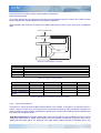
2
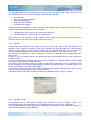
AXM DRIVE OPERATION
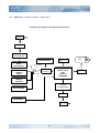
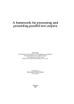
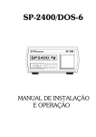
The AxM is a programmable platform for brushless servomotors control. The regulation and control functions
are managed by a firmware integrated into the drive itself. Some algorithms allow to control motor speed and
current and to accomplish positioning functions with trapezoidal or step profile, electric shafts, and step
motors simulators. Again: interfaces with peripherals as: encoder inputs, analog-digital inputs and outputs,
fieldbus inputs and outputs are currently run. AxM is supplied with control pushbuttons and led display for
alarms signals.
On the drive is available a serial interface RS 232 by which is possible parametrize and monito the operating
conditions using dedicated software environments. (see par. 3.3): The use of the parametric interface makes
it easy and versatile the drive configuration.
In addition to the integrated firmware, in the AxM drive is present a software module for dedicated
applications execution, developed in PLC language, according to the international standard IEC 1131-3. The
activation of dedicated applications grants a high freedom in use of Analog-digital and makes possible the
implementation of additional performances not included in the drive base operation. The development,
compilation and downloading into the drive of the user applications, are carried out by a dedicated Phase
Motion Control software environment (see par. 9.1).
motor
Digital I/O
Analog
I/O
Encoders
DRIVE AxM
PC
PARAMETERS
COCKPIT
CONFIG.
REGULATION AND
CONTROL FIRMWARE
RS 232
GPLC
COMPILED
APPLICATION
PROGRAM
Fieldbus
Led
Keyboard
5
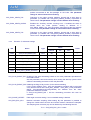
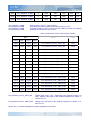
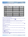
2.1
Base mode
The mode base, or “default”, allows the use the drive without the loading of a dedicated application (PLC)
and also with no remote control on the Can line. Phase Motion Control supplies the AXM drive scheduled for
“default” mode operation. In this mode the motor current and speed can be controlled.
Commands and controls are given by the activation of suitable signals to the digital inputs and the current
and speed references to the Analog inputs.
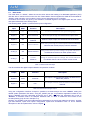
The following table (Table 2.1) resumes the inputs configuration.
Input
Abbr.
Function
Description
Digital 0
DI0
Drive enabling
The drive is enabled on the input raising edge.
Digital 1
DI1
Zero reference
When the input is high, the references are put to zero.
Digital 2
DI2
Polarity
inversion
When the input is high, the set references are inverted.
Digital 6
DI6
Control selector
When the input is high, the motor speed control is selected,
otherwise the current (torque) control is selected.
Analog 0
AI0
Speed reference
Acting on the drive input AI0 voltage, the speed reference is
modified when the drive is under speed control.
Analog 1
AI1
Current
reference
Acting on the drive input AI1 voltage, the current reference
is modified when the drive is under current control
Table 2.1: Base mode used input
The drive enables the digital outputs related to its operation condition.
Output
Abbr.
Function
Description
Digital 0
DO0
Drive Ok
The output is active when the drive is enabled and no
alarms are present.
Digital 1
DO1
Run
The output is active when the refernce command are
reached.
Table 2.2: Base mode managed output
Using the configuration interface Cockpit it’s possible to activate always the mode “default”, setting the
related system parameter IPA 18051, SYS_SEL_MODE (see par. 4.8) whatever application loaded on the
drive is disabled until such parameter should be set to “Plc”. Otherwise this parameter can be set to
“Remote”, to transform AxM in a CANopen standard node, or “Test” to enable the test routine for the
encoder phasing (only sincos in the Mplc 4.0).
Similarly, it’s possible to set the fundamental drive parameters, such as those related to the motor, encoder
type and features, inputs and outputs configuration, speed and acceleration limits. To find a detailed
description or the drive parameters, refer to Chapter 4.
6
2.2
Mode user applications (PLC)
In addition to the base functions, could be necessary the development of additional performances. On such
subject Phase Motion Control supplies some base applications normally satisfying the more common control
requirements. The activation of such dedicated applications requires theyr downloading into the drive and
the setting to “Plc” of the system parameter SYS_SEL_MODE. A detailed description of the supplied
applications is developed in the chap. 7.
For very special control exigencies, the user can develop and execute his own applications, making use of
the AxM drive extreme versatility to satisfy a very large range of control/regulation conditions and to fit the
specific configurations of input/output interfaces and of external communication. For development,
compilation and execution of dedicated applications, refer to the chap. 8.
As for the mode base applications, the user application activation requires to set at “Plc” the system
parameter SYS_SEL_MODE.
3
START UP
Following are listed all operations to be carefully completed for the first AxM drive start up.
•
•
•
•
Connect the motor to the drive following the diagrams of the “AxM User Manual”.
Connect the drive to the auxiliary power supply 24V.
Connect a PC COM output to the drive RS232 serial port (S1) with a serial null-modem cable
(female-female).
Activate the Cockpit configuration tool to configure the fundamental parameters.
We pass over the first three points; for them refer to related connection diagrams of the user manual.
Following you can found the all the procedures for the configuration of the drive.
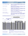
3.1
Led display
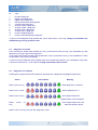
When switched on, the drive lights for an instant all the leds, then in sequence the led 0 for ab. one second
and led 7 flashing at 1 Hz frquency, thus indicating the drive correct operative condition.
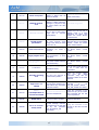
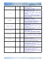
During the drive normal operation, following operative conditions are monitorated on the led display (more
than one signal con be on together).
Operative conditions
Drive condition
Led
on
Drive Ok
7
Serial
communication
6
Lighting mode
Description
1 Hz flashing
The drive is Non Enabled without alarms.
Always on
The drive is Enabled without alarms.
Variable frequency flashing
The drive has a communication in progress
with a remote PC on the serial line.
7
CAN interface
state
if
SYS_CANOPEN_
ENABLED = ON
Limite di corrente
6
5
Always on
Drive on OPERATIVE state
Flashing
Drive on PRE-OPERATIVO state
Always off
Drive on Hardware ERROR state – Bus Off
Variable flashing
The drive is supplying a current equal to the
limit value.
Table 3.1: Led meaning
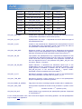
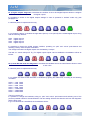
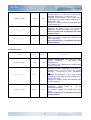
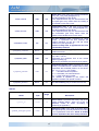
When the drive is in alarm or in error, all signals related to the operative condition are cancelled and the leds
from 0 to 4 show the alarm code. A detailed description of all alarm active on the AxM drive is reported in
chap. 11.1 Appendix 1.
Alarm conditions
Drive condition
Led on
Lighting mode
Description
Alarm
0,1,2,3,4
1 Hz flashing
Drive in alarm: the binary code of the active
alarm is shown. Refer to §11.1 Appendix 1 for
the individual alarm codes and descriptions.
System fault
0,1,2,3,4,5,6,7
1 Hz flashing
Boot error
6
Fix
System fault originated by a control and
regulation firmware error.
Contact the Phase Motion Control Customer
care service.
At the system start up, an initialization error of
the control and regulation firmware occurred.
Contact the Phase Motion Control Customer
care service.
Table 3.2: Allarm signaling
Moreover, during the firmware download procedure the follows led are on:
• The led 6 on segnalizes the drive syncronization
• Also the led 6 is flashing during the code download from the PC
• The led 3 on for few seconds segnalizes the Dsp code download
• All led flashing for a reset cycle.
Refer to par. 3.6 For the complete procedure.
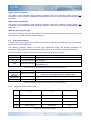
3.2
Drive parametrization
The fundamental drive parameters set up can be suitable for the system the user wants to control: it’s
necessary, therefore, to accomplish a preliminary drive configuration, setting parameters such as: motor type
and features, encoder, limits and gains etc
For a detailed description of all drive system parameters (among them the factory set values) refer to chap 4.
Follows a description of the procedures for drive configuration, introducing the user to the software tool
“Cockpit” utilization: for its detailed description refer to the related Manual.
8
3.3
The Cockpit configuration tool
COCKPIT is a program running under Windows 95/NT: it allows to configure the digital AxM and AxV drives
and the TW motors through serial interface RS232 or CANopen bus.
It’s main features are:
•
•
•
•
•
•
•
•
Serial communication RS232 (MODBUS protocol), or CANopen with CANpc interface (see istruction
manual, doc. N° SP02002)
Drive identification and control.
Use of graphic pages in HTML format.
Drive parameter reading and writing, copying, transferring and saving on file.
Parameters saving in the drive flash memory.
Drive control and monitoring.
Drive firmware updating.
Initialization and remote control through the Control Panel utility.
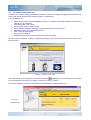
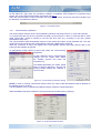
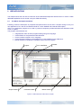
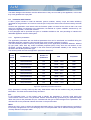
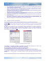
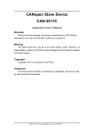
As soon Cockpit is selected, it starts in “Application Manager” mode. The introductory screen is shown in the
following figure.
Figure 3.1: Principal screen view
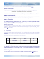
After selected the “AxM” target type, press the suitable key
(Connect) on the instrument bar, to activate
the communication with the drive (or select “Connect” from menu “Target”).
On this new window you have the actual firmware and application software indications.
Figure 3.2:
AxM Main page
9
On the status bar, righy down, the connection condition is visualized: when problems in connection fixing
arouse, the communicayion parameters must be set (see 3.3.1).
When the communication is active, the status bar at low of the screen, shows the connection condition and
the presence of possible drive alarms.
Figure 3.3: Connection active
3.3.1
Communication parameters
The communication with the drive is accomplished by Modbus multi-drop protocol, on a RS 232 serial line.
To communicate with the drive it’s therefore necessary a RS 232 port on the PC connected with a serial
cable (null-modem, female to female) to the RS 232 drive port (S1), according to the user manual
specifications (Cap. 8.5).
The communication starts automatically when the user selects and opens a new parameter file. The user
can disconnect and reconnect the communication using the suitable menu command.
When the connection is active, the related menu voice appears selected (tick sign) and the digit on the
instrument bar appears as pressed.
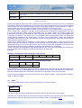
An appropriate window allows to select and modify the communication
parameters.
To find it select the voice “Communication
settings” from the “Target” menu. Select
the modbus protocol and press the
Properties key.
The default parameters are: COM1, 38400
baud, no parity, 8 data bits, 1 stop bit. The
protocol default settings are: Address 0,
Timeout 1000.
Figure 3.4: Communication parameters setting
NOTE: In order to correctly communicate with the drive, the value of the field Address must be identical to
the address given to the drive.
The drive address can be verified and modified using the windows “Target information”:
When the address has been modified, it must be saved into the flash memory (Set key).
Figure 3.5: System information window
10
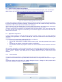
3.3.2
Parameters use
The AxM digital platforms are fully programmable and all parameters sets for the system configuration and
operation are resident in the memory.
When the drive is turned on the first time, it is started in “default” mode, using a default parameters table
allowing to control, with limited performances, the most part of the Phase Motion Control standard brushless
motors. The default configuration parameters are saved in the drive flash memory when assembled in
factory; a copy of the default table is included by Setup in the Cockpit work directory, so that it will be
possible in every moment and in all cases go back to the initial configuration.
Starting up, the Cockpit configuration tool asks to load the system parameters table (file sys_AxM_04.par)
from the work directory with the “Open” command of the “File” menu.
the parameters can be organized in different “logic” menus, so allowing to visualize of the full series or of a
subset only.
Some fundamental parameters are also accessible in form of graphic HTML pages.
Every parameter is defined by following fields:
IPA
parameter index, as defined by the MODBUS protocol;
NAME
mnemonic name, used for parameter identification;
TYPE
data type of the parameter (int, word, long, dword, float, bool);
VALUE
includes the actual value as read by Cockpit;
UNIT
reference to the parameter unit measure;
DESCRIPTION Explicit parameter description;
NOTE
(in the status bar) visualizes optional information related to the selected parameter.
The user can only modify the value field of each parameter.
Now it’s possible to establish a connection with the drive: it’s advisable, at the first start up, to fully read all
drive parameters, to verify if the used table is consistent with the “Read all” command of the “Parameters”
key of the instruments bar).
menu (or with the Read all
The parameter singularly selected can be read using the “Read parameter” command of the “Parameters”
key of the instruments bar).
menu (Read
The drive parameters can be now modified as desired. When a value is modified, it is visualized in red, to
indicate that it is not still written in the drive. After every parameter modification, it is necessary to confirm
with Enter and to write it in the drive with the “Write parameter” command of the “Parameters” menu (or with
key of the instrument bar).
the Write
It’s possible to write all parameters of the selected menu using the command “Write all” of the menu
key of the instrument bar).
“Parameters“ (or using the Write all
To speed up the reading and writing operations, the On-line mode is usable, through the suitable command
key of the instrument bar), the Cockpit
“On line mode” of the menu “Parameters” (or using the On line
instantly updates the parameters values every timethey are selected. Same way it writes instantly on the
drive the value of parameters modified by the user.
When parameters have been optimized for the desired operation, the used table can be saved in a file to be
copied or used subsequently (command “Save as” on the “File” menù).
The modified data are written directly in the program memory, but being such memory not permanent, the
modifications must be saved to avoid to loose them at the system reset. The command “Save parameters” of
key of the instrument bar), starts the parameters saving in the drive
the menu “Parameters” (or the Save
flash memory. The drive will pass to an alarm status of Lock drive shown in the left part of the status bar.
Figure 3.6: Alarm status after parameters saving
After the drive reset, the modified system parameters are fully active and it will possible to test or quickly
start the drive calling the Control Panel and enabling the panel inputs, in accord with the planned
combinations of the digital and Analog inputs for the “default” operative mode. (see Table 2.1).
11
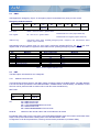
3.3.3
Control Panel
The Control Panel allows to monitor and control the I/O interface of the drive using the communication line. It
or from
can be activated from the configuration tool itself pressing the key related to the instrument bar
the command “Control Panel” of the menu “Target”. When the first time activated, the “Panel Inputs Enable”
option is disabled and the Control Panel acts as a monitor of the current status of the physical I/O.
If the user selects the “Panel inputs enable” option, the drive digital and analog physical inputs are virtually
disconnected and the control of the inputs goes to the Control Panel windows.
The “Drive outputs enable” option is activated by default: if disabled the drive physical outputs are
disconnected.
Figure 3.7: Control Panel
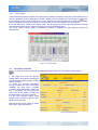
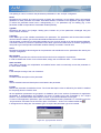
3.4
Connections checkout
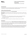
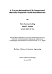
To verify the motor connections and some parameters value you can use the “monitor page”:
In this page you have the DC-link
voltage value, the heat-sink temperature
and the encoder reading values: position
and turn number.
To check the encoder connection:
turning clockwise the motor shaft (drive
diasbled) you must read a position
increment, up to 360 degree. When one
turn is completed you must read the
initial value in the position number and
the initial value +1 in the turn number.
For the drive firmware 65535 virtual
pulses are the maximum position value
equal to one motor turn.
Moreover there are the values of speed
and current limit and reference.
F
F
Figure 3.8: Monitor Page
12
3.5
Operation monitoring
During the drive operation is useful to control that the drive itself should not be in alarm condition and that
the internal variables should be consistent with the system control.
The more simple and intuitive action is surely to monitor the drive status looking to the led displayer referring
to the tables 3.1 and 3.2 (paragraph 3.1) for the signals meaning.
If a punctual and deep monitoring action becomes necessary, is useful to connect the drive with the Cockpit
configuration tool.
Open from the configuration tool the parameters file (file with extension .par) actually loaded on the drive (in
case of first start up the file sys_AxM_01.par). The connection is automatically activated and the drive status
is visualized in the left part of the status bar.
Figure 3.9: Communication state
All activated alarms can be visualized by a dedicated windows, opened with the command “Active Alarms” of
key on the instruments bar.
the “Target” menu or by
Figure 3.10: Active alarm window
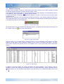
Using the History key the “Alarm history” windows is shown: in it are visualized the last 25 alarms occurred,
together with the value of some significant variables, at the moment of the alarm intervention. The more
recent alarm is shown in the position (Idx) 25. It’s possible to print or save on a file the content of the whole
window.
Figure 3.11: Alarm istory
In addition to the alarm status, the system parameters file makes available a menu “Monitor” where is
possible to control same internal drive variables, such as: encoder dimensions, speed, requested current,
delivered current, etc. The variables are grouped in logic sub-menus. For a detailed descrption refer to the
par. 4.
13
3.6
Firmware upgrading
Firmware upgrades are periodically available on the web site www.phase.it new functionality and/or software
evolution, processing from Phase Motion Control laboratories, are fuse and a new firmware version is
released.
To upload this, open a system table and select “Load firmware” from “Service” menù; the follow window will
appear:
Figure 3.12: Load Firmware and synchronization window
With “Browse” button select the firmware file to download (Ex. “MPlc4_0.sre”).
Press before “Syncro” and after “Reset” to syncronize the drive.
When “Syncronization executed” appear, in the “operation” window press “Load” to star the downloading.
At the end of the procedure the drive will be automatically reset.
NOTE:
The drive will be unusable if any troubles occurs during this operation (Ex. Lost of 24V supply, PC
connection problem, …). You have to repeat the firmware upload in order to get back the drive working.
If is not possible connecting the drive with the PC, syncronize it pressing “Syncro” button, then remove the
24V supply and connect now them.
3.7
Electronic namplate use
The new serial Endat encoder allow to store data in non-valatile mode.
Therefore it is possible to store some parameters with the motor features and execute a coarse configuration
based on this parameters.
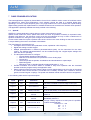
3.7.1
Plug & play
The “autoset” procedure is executed automatically from AxM drive when the Endat encoder connected has a
set of motor parameters unlike with the same parameters stored inside the drive.
In this case the drive upgrade is own set of motor parameters and execute a configuration of some other
parameters, like current and speed gains to adapt to the motor.
Here there are all the parameters modified from this procedure.
14
Drive Parameters
SYS_MOT_N_POLES
SYS_MOT_IDM
SYS_MOT_IN
SYS_ENC1_TYPE
SYS_IC_P_FAK
SYS_IC_I_FAK
SYS_IC_D_FAK
SYS_PHASE_OFFSET
SYS_SPL_SPD_FAK
SYS_SPL_POS_FAK
SYS_RG_POS_SPILM =
SYS_RG_NEG_SPILM
SYS_RG_CW_ACC / DEC =
SYS_RG_CCW_ACC / DEC
SYS_SPL_FILT
Menù:
Motor Parameters
Encoders/Monitor/Primary/Endat
SYS_MOT_POLES
SYS_MOT_I_NOM_ASSE_BLOC x 2
SYS_MOT_I_NOM_SPD
Endat
SYS_MOT_INDUTT x 450
(Ultract)
2000
(Ul T)
SYS_MOT_INDUTT x 225
(Ultract)
4000
(Ul T)
0
(Ultract)
400
(Ul T)
SYS_ENDAT_FASE
SYS_MOT_M_INERZ / SYS_MOT_KT x 250
SYS_MOT_M_INERZ / SYS_MOT_KT x 125
SYS_MOT_NOM_SPD
SYS_MOT_KT x SYS_MOT_IDM / (SYS_MOT_M_INERZ x 0.1)
0.5
Table 3.3: parameters modified by the autosetting procedure
3.7.2
Options
The SYS_PLUG_ENDAT_EN parameter (menù: Encoders/Advanced; par. 4.2.2) allow to start the auto
setting procedure independently from the motor parameters.
Setting ON this parameter, saving it and resetting the drive, the firmware will read again the motor features
from the encoder and doing again the configuration of the system parameters (table 3.8), leaving
SYS_PLUG_ENDAT_EN = OFF;
With the SYS_PLUG_ENDAT_DIS parameter is possible to completely disable the autosettings procedure,
also if a new motor is connected.
If is connected a motor with a not configured Endat encoder, the firmware overwrite all the motor parameters
to 0 (Menù: Encoders/Monitor/Primary/Endat) but it don’t execute any modification of the system parameters.
In this case no alarms are segnalized.
If subsequently an auto-configuration is requested, by the SYS_PLUG_ENDAT_EN parameter, the firmware
do not execute this procedure and the alarm “Invalid system parameters” is showed. However the
SYS_PLUG_ENDAT_EN is resetted by the firmware and after a new drive reset the alarm disappear.
3.8
Test routine use
Selecting SYS_SEL_MODE = Test (Menù “System”, par. 4.8) the test routine are enableb. Therefore using
the parameters in the “Test” menù it is possible to execute the encoder phasing (in the 2.x firmware only for
SINCOS encoder) or the current loop calibration.
The SYS_SEL_TEST parameter allow to select the desired test:
Encoder Phasing
Current Loop Calibration
Æ to verify or execute the encoder phasing
Æ to execute the current loop calibration
15
3.8.1
Encoder phasing
In this mode the only parameter that could be modified is FAS_CURR (menù: “Test/Encoder Phasing”,
paragraph 4.9.1) it limit the current used for during the test. Set it less than the nominal current of the motor.
NOTE: To execute correctly thi procedure the motor shaft must be free of load.
The digital input 0 (DI0) enable the drive and it start to supply the motor current, in open loop, up to the
encoder index is found. The PH_ERR parameter shows at this point the value of phase error, in degree.
Unlock and move now the encoder position to reduce this value up to 0; values around +/- 2 degree are
enough to have a good feedback. Lock again the encoder, disable the drive and move the motor shaft, then
do again the same procedure to verify the calibration.
3.8.2
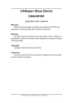
Current loop calibration
To execute the current loop calibration the drive supply two motor phases with a square wave with
magnitude and duti-cycle configurable. All this parameters are in the “Test/Current loop calibration” (see
paragraph 4.9.2) and are normally setted to have a current request from 0.5A to 1.5A with a 100ms period.
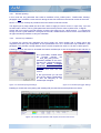
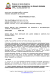
Following we show how have to be setted the internal oscilloscope to see the supplied current and then to
execute the calibration.
The “sysCurrReq” variable shoes
the
currente
request;
the
SYS_SEL_DSP_DATO1
parameter (settable in the menù:
Current loop / Advanced settings,
see par. Errore. L'origine
riferimento
non
è
stata
trovata.3)
shows in this case the real
current.
In the right window you can see
how set the trigger configuration
to start the sampling of the
oscilloscope immagine.
Figure 3.13: Oscilloscope signal settings
Figure 3.14: Oscilloscope trigger settings
Enabling for a while the drive (setting and resetting DI0) the test start and the aquisition it’s shows.
Figure 3.15:Oscilloscope aquisition with request current and real current
16
The current loop calibration is obtained setting the current loop gain (menù: Current loop; the modification of
this parameters are activate when the drive is disable).
See par. 4.3 for the starting set of current gains.
4
SYSTEM PARAMETERS
The system parameters are parameters pre-defined in the drive: then they are present in every application.
They are accessible from Cockpit in the file “sys_AxM_04.par”.
They are organized in hierarchical menus and all depend from “AX_M drive” menu and can be divided in
reading and writing parameters (IPA between 18000 and 20999) and read-only parameters (IPA from 21000
ahead).
NOTE: It’s possible to modify the reading-writing parameters by parameters saving.
Generally, unless indicated, the modifications to system parameters will be active at the further system reset
(see par. 3.3.2).
Generally the parameters are structured in hierarchic sub-groups collecting all parameters related to the
different firmware services.
The sub-groups are in turn divided in logic blocks. Generally there will be some principal sections collecting
the more commonly used parameters. Moreover for some services a section called “Advanced settings”
will be found. The default values set by the manufacturer for these parameters are suitable in most cases.
For particular applications only, it can be necessary to set the parameters of this section in order to optimize
the drive performances. The user must be aware that the changes introduced assume a very deep
knowledge of the details connected to drive firmware and functional control blocks implementation.
Finally, in several sections there is a “Monitor” sub-group including all diagnostic parameters allowing to
monitor the AxM drive status.
Following the list and description of all system parameters, grouped according to different services, is
reported.
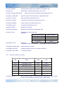
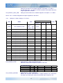
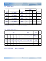
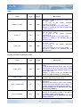
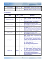
4.1
Motor
Value
IPA
Name
Default
Min
Max
Unit of
measure
Type
18240
SYS_MOT_N_POLES
Word
8
0
100
Nr.
18241
SYS_MOT_IDM
Float
3.00
0.00
100.00
Arms
18242
SYS_MOT_IN
Float
1.00
0.00
100.00
Arms
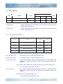
SYS_MOT_N_POLE:
Motor pole number setting.
SYS_MOT_IDM:
Motor current limit setting.
SYS_MOT_N_POLES:
Motor nominal current setting.
17
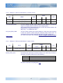
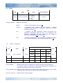
4.2
Encoders
Value
IPA
Name
Type
18230
SYS_ENC1_TYPE
18231
SYS_ENC1_CY_REV
Enum
0
1
2
3
4
16
Value
Null
Digit
Resolver
Sincos
Hall
Endat
Word
Enum
0 Null
1 Digit
6 Freq
Default
Min
Max
1
(SinCos)
0
(Absent)
16
(Endat)
---
2048
1
8192
Imp.Enc
0
(Absent)
0
(Absent)
1
(Digital)
1
8192
18232
SYS_ENC2_TYPE
18233
SYS_ENC2_CY_REV
Word
1024
18235
SYS_SE_ENABLE
Bool
Off
Imp.Enc
---
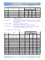
SYS_ENC1_TYPE:
Primary encoder type used for retroaction of the speed/space ring setting.
SYS_ENC1_CY_REV:
Primary encoder pulses number per revolution setting. In case of Resolver,
Hall or Endat set the value 1024.
SYS_ENC2_TYPE:
Auxiliary encoder type setting. 0
SYS_ENC2_CY_REV
Auxiliary encoder pulses number per revolution setting / Number of
simulated pulses of the encoder simulation output, if enabled.
NOTE: In the AxM firmware release 2.0 the number of simulated pulses can be set only on multiple by 2.
SYS_SE_ENABLE
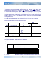
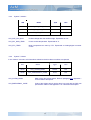
4.2.1
Enabling of the encoder simulation on auxiliary encoder port (C1).
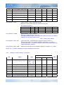
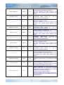
Encoders ª Index
In the sub-menu “Encoders – Index are set the parameters related to the use and control of the index for
encoder SinCos or Digital. ”
Value
IPA
Name
Type
Value
Default
Min
Max
18050
SYS_ENC1_INDEX_ALARM
Bool
Off
---
18060
SYS_ENC2_INDEX_ALARM
Bool
Off
---
18170
SYS_ENC1_INDEX_TOL
Word
2
0
512
CntVi
18171
SYS_ENC2_INDEX_TOL
Word
2
0
512
CntVi
SYS_ENC1_INDEX_ALARM:
Enables the “Encoder counting error”. If enabled the alarm is issued when
the index position reading is different of ± SYS_ENC1_INDEX_TOL from the
18
position memorized at the first passage on the index. The parameter
change is active without drive resetting.
SYS_ENC1_INDEX_TOL:
Tolerance on the index counting readings, beyond that a drive alarm is
generated. (If enabled with SYS_ENC1_INDEX_ALARM). Expressed as
virtual counts. The parameter change is active without drive resetting.
SYS_ENC2_INDEX_ALARM:
Enables the “Auxiliary encoder counting error”. If enabled the alarm is
issued when the index position reading is different of ±
SYS_ENC2_INDEX_TOL from the position memorized at the first passage
on the index. The parameter change is active without drive resetting.
SYS_ENC2_INDEX_TOL:
Tolerance on the index counting readings, beyond that a drive alarm is
generated. (If enabled with SYS_ENC2_INDEX_ALARM). Expressed as
virtual counts. The parameter change is active without drive resetting.
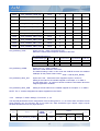
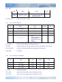
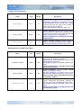
4.2.2
Encoders ª Advanced settings
Value
IPA
Name
Type
Name
Default
Min
Max
18055
SYS_PLUG_ENDAT_EN
Bool
Off
---
18061
SYS_PLUG_ENDAT_DIS
Bool
Off
---
18163
SYS_PHASE_OFFSET
Word
0
0
65535
CntVi
18200
SYS_RES_ECC_ADJ
Int
35
-30
150
Nr.
18221
SYS_RIP_MAX_FREQ
Float
100
2
1000
kHz
18234
SYS_AD_RIPPLE_LIM
Word
100
0
128
Nr.
18238
SYS_ENC1_INDEX_DISABLE
Bool
Off
---
SYS_PLUG_ENDAT_EN: Enabling of the drive autosetting; based on the motor parameters provided from
the endat encoder.
Set this parameter, save and reset the drive; during the start-up cycle the drive
will do the autosetting and reset to OFF this parameter.
SYS_PLUG_ENDAT_DIS: Disabling the Plug & Play function for the drive autosetting.
If SYS_PLUG_ENDAT_DIS = OFF the autosetting procedure will be executed
every time the values of the SYS_MOT_MODEL + SYS_MOT_TYPE parameters
(Menù: Encoders/Moniror/Primarye/Endat) are different from the same
parameters inside the encoder.
If SYS_PLUG_ENDAT_DIS = ON the autosetting procedure will never be
executed.
SYS_PHASE_OFFSET:
Field angle correction setting; if a non standard setting is desired.
SYS_RES_ECC_ADJ:
Resolver excitation sampling offset setting. By this parameter is possible to
change the instant when the Sine and Cosine resolver channels are sampled.
The sampling time correction (us) can be obtained by the following formula:
Toffset = SYS_RES_ECC_ADJ * 0.32us
19
The factory setting aims to sampling optimization in order to get a max.
signal/noise (S/N) ratio. However external factors can make necessary a
sampling instant fine regulation: modify the parameter to increase the sampled
signal amplitude on both resolver channel, in order to optimize S/N. Verify (by
oscilloscope window) that the signals “sysResAdc0 / 1” reach the max (1023) and
min (0) values without limitations or distortions.
The parameter change is active without drive resetting.
SYS_RIP_MAX_FREQ:
Limit value for the frequency of the encoder simulation waves.
SYS_AD_RIPPLE_LIM:
Ripple tolerated limit value on encoder Analog channels. Expressed in counts for
the Analog-digital converter. The settable values are included between 0 and
128. If the measured ripple would exceed such parameter, the related alarm
should activate.
NOTE: Setting 128 on this parameter the “Encoder counting error” alarm will be disable!
SYS_ENC1_INDEX_DISABLE :
4.2.3
Disable the index reading, in case of Digital or Sincos encoder.
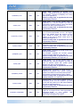
Encoders ª Monitorª Primary
IPA
Name
Type
Unit
21070*
SYS_ENC1_VI_PO
Word
CntVi
21072*
SYS_ENC1_I_VI_PO_MEMO
Word
CntVi
21073*
SYS_ENC1_VI_TU
Long
N°
21078*
SYS_ENC1_I_VI_TU
Long
N°
21110*
SYS_ENC1_I_VI_PO
Word
CntVi
24681*
SYS_ENC1_PE_SP
Long
(CntVi/250us)*216
SYS_ENC1_VI_PO:
Motor position on the turn as read by the primary encoder. Expressed as
virtual counts (CntVi).
1 encoder turn = 65535 virtual cnt
SYS_ENC1_VI_TU:
θ [CntVi ] = 65536 ⋅
1
θ [rad ]
2π
Encoder revolution number as read by the primary encoder.
SYS_ENC1_I_VI_PO_MEMO: Position on the revolution of first primary encoder index. Expressed as virtual
counts (CntVi). Only for Sincos and Digit encoder.
SYS_ENC1_I_VI_PO:
Position on the revolution of first primary encoder index. Expressed as virtual
counts (CntVi). Only for Sincos and Digit encoder.
SYS_ENC1_I_VI_TU:
Position in turns of the primary encoder first index. Only for Sincos and Digit
encoder.
20
SYS_ENC1_PE_SP:
Motor speed as read by the primary encoder. The speed is computed as
positions difference ( SYS_ENC1_VI_PO ) in 250us and extended to 32 bit.
The unit of measure is (CntVi/250us)*2exp16.
⎡ CntVi 16 ⎤
1
⋅ 2 ⎥ → 16 ⋅
ω⎢
2
⎣ 250 µs
⎦
2π [rad ] ⋅ 1
60[s ]
⎡ rad ⎤
250 ⋅ 10 − 6 [s ]
= ω⎢
→
= ω [rpm]
⎥
65536[CntVi ]
2π [rad ]
⎣ s ⎦
4.2.3.1 Encoders ª Monitor ª Primary ª Resolver
In this section is possible to monitor the resolver specific parameters.
IPA
Name
Type
Unit
21060*
SYS_RES_ADC_COSE
Word
N°
21061*
SYS_RES_ADC_SINE
Word
N°
21062*
SYS_RES_ABS_COSE
Word
N°
21063*
SYS_RES_ABS_SINE
Word
N°
21064*
SYS_RES_CH_OFF_1
Word
N°
21065*
SYS_RES_CH_OFF_2
Word
N°
21120*
SYS_AD_RIPPLE
Int
N°
SYS_RES_ADC_COSE:
Analog level of the cosine channel. Expressed as Analog-digital converter
counts.
SYS_RES_ADC_SINE:
Analog level of the sine channel. Expressed as Analog-digital converter
counts.
SYS_RES_ABS_COSE:
Computed cosine value.
SYS_RES_ABS_SINE:
Computed sine value.
SYS_AD_RIPPLE:
Ripple value on the resolver Analog channels. Expressed as Analog-digital
converter counts.
SYS_RES_CH_OFF_1:
Offset of the adc resolver channel. Expressed as Analog-digital converter
counts.
SYS_RES_CH_OFF_2:
Offset of the adc resolver channel. Expressed as Analog-digital converter
counts.
21
4.2.3.2 Encoders ª Monitor ª Primary ª Endat
In this section is possible to monitor the parameters as read by endat among these the electronic nameplate
data for drive autocalibration.
IPA
Name
Type
Unit
18401*
SYS_MOT_SERIAL
Dword
N°
18402*
SYS_MOT_DATE
Dword
N°
18403*
SYS_MOT_MODEL
Enum
---
18404*
SYS_MOT_INDUCT
Float
mH
18405*
SYS_MOT_RESIST
Float
ohm
18406*
SYS_MOT_KT
Float
Nm / Arms
18407*
SYS_MOT_I_ZERO_SPD
Float
Arms
18408*
SYS_MOT_I_NOM_SPD
Float
Arms
18409*
SYS_MOT_I_PEAK
Float
Arms
18410*
SYS_MOT_K_TERM
Word
s
18411*
SYS_MOT_INERTIA
Float
mKgm^2
18412*
SYS_ENDAT_PHASE
Word
CntVi
18413*
SYS_MOT_POLES
Word
N°
18414*
SYS_MOT_NOM_SPD
Float
rad / s
18415*
SYS_MOT_TYPE
Dword
---
18430*
SYS_ENDAT_TYPE
Enum
---
18431*
SYS_ENDAT_FORM_DATA
Word
N°
18432*
SYS_ENDAT_TURN_NR
Word
N°
18433*
SYS_ENDAT_TURN_CNT
Word
N°
SYS_MOT_SERIAL_NR
Motor serial number.
SYS_MOT_DATA_PROD
Manufacturing date. Expressed in the following format:
e.g. 20021218 = Dec 18, 2002.
SYS_MOT_MODEL
Motor model.
SYS_MOT_INDUTT
Code
Model
UL 2
UL 3
UL T
Ultract II
Ultract III
Ultract T
Value of phase-to-phase motor inductance. Expressed in mH.
22
SYS_MOT_RESIST
Value of phase-to-phase motor resistance. Expressed in ohm.
SYS_MOT_KT
Motor torque costant (Kt). Expressed in Nm / Arms.
SYS_MOT_I_NOM_ASSE_BLOC
Nominal current with locked shaft (In0). Expressed in Arms.
SYS_MOT_I_NOM_SPD
Nominal current at nominal speed (In). Expressed in Arms.
SYS_MOT_I_PICCO
Peak current (Ipk). Expressed in Arms.
SYS_MOT_K_TERM
Thermal time constant (ta). Expressed in seconds.
SYS_MOT_M_INERZ
Inertia moment (Jm). Expressed in Kgm^2.
SYS_ENDAT_FASE
Endat phase. Expressed in CntVi.
SYS_MOT_POLES
Number of motor poles.
SYS_MOT_NOM_SPD
Nominal motor speed (wn). Expressed in rad/s.
SYS_MOT_TYPE
Phase Motion Control motor code.
Examples:
SYS_ENDAT_TYPE
Codice Standard Phase
Codice Parametro
Ul22.50.5
Ul405.30.3
T503.40.3
Ul708.15.3
22505
405303
503403
708153
Endat type.
MÆabsolute single-turn (17bit data)
NÆabsolute multi-turn (29bit data)
SYS_ENDAT_FORM_DATA
Absolute position bit number.
SYS_ENDAT_NR_GIRI
Absolute revolutions number. For multiturn endat only.
SYS_ENDAT_CNT_GIRO
Counts per revolution.
4.2.4
Encoders ª Monitorª Auxiliary
IPA
Name
Type
Unit
21074*
SYS_ENC2_VI_PO
Word
CntVi
21075*
SYS_ENC2_PE_SP
Long
(CntVi/250us)*216
21076*
SYS_ENC2_I_VI_PO_MEMO
Word
CntVi
21077*
SYS_ENC2_VI_TU
Long
N°
21079*
SYS_ENC2_I_VI_TU
Long
N°
21111*
SYS_ENC2_I_VI_PO
Word
CntVi
SYS_ENC2_VI_PO:
Motor position as read by auxiliary encoder. Expressed in virtual counts
(CntVi). 1 turn is 65536 virtual counts as for the main encoder.
23
SYS_ENC2_VI_TU:
Number of encoder turns as read by auxiliary encoder.
SYS_ENC2_PE_SP:
Motor rotating speed as read by auxiliary encoder. Speed is computed as
positions difference (SYS_ENC2_VI_PO) in 250us and extended to 32 bit.
The unit of measure is (CntVi/250us)*2exp16.
SYS_ENC2_I_VI_PO_MEMO: Position on the turn of the first index of the auxiliary encoder. Expressed in
virtual counts (CntVi).
SYS_ENC2_I_VI_PO:
Position on the turn of the index of the auxiliary encoder. Expressed in virtual
counts (CntVi).
SYS_ENC2_I_VI_TU:
Position in turns of first index of the auxiliary encoder.
4.3
Current loop
The default configuration of current gains is usually enough for most of the Phase Motion Control motor; to
obtain the best performaces use the furmulas in the following table.
Valore
IPA
Name
Default
Ideal
Value for
Ultract 2 / 3
Ideale
Value for
Ultract T
Min
Max
Type
Unit
18100
SYS_IC_P_FAK
Word
3000
Lw * 450
2000
0
65535
N°
18101
SYS_IC_I_FAK
Word
1500
Lw * 225
4000
0
65535
N°
18102
SYS_IC_D_FAK
Word
0
0
400
0
65535
N°
SYS_IC_P_FAK:
Current loop proportional gain. It is actuated when the drive is disabled.
SYS_IC_I_FAK:
Current loop integral gain. It is actuated when the drive is disabled.
SYS_IC_D_FAK:
Current loop differential gain. It is actuated when the drive is disabled.
You need to reset the drive to activate the modifications of this parameters.
4.3.1
Current loop ª Monitor
IPA
Name
Type
Unit
21000*
SYS_DSP_CURR_QUAD
Int
Cnt
21001*
SYS_DSP_CURR_DIR
Int
Cnt
21002*
SYS_DSP_RHO
Word
CntVi
21003*
SYS_DSP_CONTROL
Word
Hex
21004*
SYS_DSP_DATO1
Int
N°
21005*
SYS_DSP_DATO2
Int
N°
24
21006*
SYS_DSP_DATO3
Word
N°
21007*
SYS_DSP_STATUS
Word
Hex
21100*
SYS_DSP_IU_ANA
Int
Cnt
21101*
SYS_DSP_IV_ANA
Int
Cnt
The parameters with IPA included between 21000 and 21007 have been defined and dedicated to internal
use. Only if the drive is enabled, the following parameters have a meaning for the user.
SYS_DSP_CURR_QUAD:
Quadrature current reference. Expressed in counts. The conversion
factor to obtain current expressed in Arms is 0,01 Arms/cnts. Apply
therefore:
Iq = SYS_DSP_CURR_QUAD * 0.01
In speed/position loop such value coincides with the parameter
SYS_SPL_W_OUT of the “Monitor – Speed/Position loop” submenu.
SYS_DSP_CURR_DIR:
Direct current reference. Expressed in counts. The conversion factor
to obtain current expressed in Arms is 0,01 Arms/cnts. Apply
therefore:
Id = SYS_DSP_CURR_DIR * 0.01
It represents the contribution of the direct current that in pasrticular
applications is required in the motor phase currents computations.
SYS_DSP_RHO:
Field angle. Expressed in virtual counts (1 mechanical revolution =
65535 virtual counts). It represents the position on the mechanical
revolution, or: Pel = Pmecc * N°cp where
= electric position
Pel
= position on the mechanical revolution (SYS_SPL_VI_PO)
Pmecc
= motor polar pairs number.
N°cp
SYS_DSP_IU_ANA:
Motor phase U current. Expressed in counts. The conversion factor
to obtain current expressed in Arms is 0,00503 Arms/cnts. Apply
therefore:
Iu = SYS_DSP_IU_ANA * 0.00503
SYS_DSP_IV_ANA:
Motor phase V current. Expressed in counts. The conversion factor
to obtain current expressed in Arms is 0,00503 Arms/cnts. Apply
therefore:
Iu = SYS_DSP_IV_ANA * 0.00503
4.4
Speed position loop
Value
IPA
Name
Type
Unit
Default
Min
Max
18052
SYS_SPL_ERR_MAX_ENABLE
Bool
On
18150
SYS_SPL_POS_FAK
Word
20
0
32767
N°
18151
SYS_SPL_I_FAK
Word
0
0
32767
N°
18152
SYS_SPL_SPD_FAK
Word
40
0
32767
N°
18154
SYS_SPL_ACC_FAK
Word
0
0
32767
N°
18164
SYS_SPL_POS_ERR_MAX
Word
20000
0
65535
CntVi
25
SYS_SPL_ERR_MAX_ENABLE:
Position error limit enabling. Setting such parameter to On, the
position error computed in the speed/position loop will be limited to
SYS_SPL_POS_ERR_MAX
SYS_SPL_POS_FAK:
Position gain setting: it represents the position error in the
speed/position loop multiplication factor. The parameter change
becomes active without drive resetting.
SYS_SPL_I_FAK:
Integral gain setting: it represents the multiplication factor of all
contributions of the speed/position loop. The parameter change
becomes active without drive resetting.
SYS_SPL_SPD_FAK:
Speed gain setting: it represents the multiplication factor of the
speed error in the speed/position loop. The parameter change
becomes active without drive resetting.
SYS_SPL_ACC_FAK:
Speed differential gain setting. Still not implemented.
SYS_SPL_POS_ERR_MAX:
Position error limit setting: such parameter is active if the position
error limit with the parameter SYS_SPL_ERR_MAX_ENABLE is
enabled. Expressed in virtual counts (1 mechanical revolution =
65536 virtual cnt).
This parameter is also useful for limit the supply current when the motor shaft is blocked. Use the following
formula to evaluate the supply current:
I [Arms ] =
NOTE:
4.4.1
SYS_SPL_POS_ERR_MAX
⋅ SYS_SPL_POS_FAK
50000
For a complete parameters vision, refer to the block diagram of the speed/position loop,
Chapter 11.4 Appendix 4.
Speed position loop ª Speed profile
Value
IPA
Name
Type
Unit
Default
Min
Max
18054
SYS_RAMP_EN
Bool
On
---
18157
SYS_RG_POS_SPLIM
Float
314.000
---
---
rad/sec
18158
SYS_RG_NEG_SPLIM
Float
314.000
---
---
rad/sec
18159
SYS_RG_CW_ACC
Float
1000.0
---
---
rad/sec^2
18160
SYS_RG_CW_DEC
Float
1000.0
---
---
rad/sec^2
18161
SYS_RG_CCW_ACC
Float
1000.0
---
---
rad/sec^2
18162
SYS_RG_CCW_DEC
Float
1000.0
---
---
rad/sec^2
SYS_RAMP_EN:
Speed profile generator enabling. Setting such parameter to Off, speed
steps will be generated.
SYS_RG_POS_SPLIM:
Max. speed setting, for clockwise motor rotation. Expressed in rad/sec.
SYS_RG_POS_SPLIM:
Max. speed setting, for counterclockwise motor rotation. Expressed in
rad/sec.
26
SYS_RG_CW_ACC:
Acceleration setting,
rad/(sec*sec).
SYS_RG_CW_DEC:
Deceleration setting, for clockwise motor rotation. In rad/(sec*sec).
SYS_RG_CCW_ACC:
Acceleration setting, for counterclockwise motor rotation. In rad/(sec*sec).
SYS_RG_CCW_DEC:
Deceleration setting, for counterclockwise motor rotation. In rad/(sec*sec).
4.4.2
for
clockwise
motor
rotation.
Expressed
in
Speed position loop ª Advanced settings
Value
IPA
Name
Type
Unit
Default
Min
Max
18053
SYS_SPL_REF_EN
Bool
On
18057
SYS_SPL_POS_GEN
Bool
Off
18156
SYS_SPL_FILT
Float
0.300
0.001
1.000
N°
18245
SYS_SPL_SP_IST
Int
2
0
1000
CntVi/250us
SYS_SPL_REF_EN:
Flags setting to enabling the input references to the speed/position loop block.
Setting this parameter to Off it’s possible to set the speed, position and turns
references as inputs to the speed/position loop. Normally this parameter must
be set to On (Refer to chapter 11.4 Appendix 4).
SYS_SPL_POS_GEN:
Enabling this function the speed refence is filtered before enter in the
speed/position loop. In this mode is possible to achieve better performances in
position applications, above all where a very little overshoot is necessary.
SYS_SPL_FILT:
Speed/position loop filtering constant. It represents the time constant of the
digital filter implemented in the speed/position loop output. The filtering action
changes inversely with the parameter (1.000 = filter excluded, 0.001 max.
filtering action).By factory is setting a low filtering action. Reduce the filter
value if a filtering of speed/position loop high frequencies is really useful
(e.g. when a high noise or resolver is present).
SYS_SPL_SP_IST:
Speed hysteresis window setting. By this parameter is possible to exclude the
contributions of speed variations internal to the hysteresis window in the
speed/position loop. As default the hysteresis is deactivated. Activate the
parameter in case of positions and speed particularly jammed by noise
(i.e.: resolver).
4.4.3
Speed position loop ª Monitor
IPA
Name
Type
Unit
19018*
SYS_SPL_POS_ERR
Long
CntVi
21040*
SYS_SPL_W_OUT
Int
N°
21041*
SYS_SPL_VI_PO
Word
CntVi
27
21042*
SYS_SPL_POS_REF
DWord
CntVi*216
21044*
SYS_SPL_PE_SP
Int
CntVi/250us
21045*
SYS_SPL_PE_SP_REF
Long
(CntVi/250us)*216
21046*
SYS_SPL_VI_TU
Long
N°
21047*
SYS_SPL_TUR_REF
Long
N°
21049*
SYS_RG_RAMP_IN_CORSO
Bool
--
21052*
SYS_SPL_POS_TUR
Long
CntVi
24683*
SYS_RG_LIN_OUT
Long
(CntVi/250us)*216
SYS_SPL_POS_ERR:
Position error: represents the difference between the theoretical and the
actual position. Expressed in virtual counts (CntVi).
SYS_SPL_W_OUT:
Speed/position loop output. It represents the current reference output of
the speed/position loop.
SYS_SPL_VI_PO:
Position on the mechanical turn. Represents the actual position in input of
the speed/position loop. Expressed in virtual counts (CntVi) The value of
such parameter coincides with SYS_ENC1_VI_PO.
SYS_SPL_POS_REF:
Reference position on the mechanical turn. Represents the theoretical
position in input of the speed/position loop as computed by the reference
16
generator. Expressed as 32 bit normalized virtual counts (CntVi*2 ).
SYS_SPL_PE_SP:
Input speed in the speed/position loop. It represents the difference in 250
us between the theoretical position and the actual one. Expressed as
virtual counts every 250 us (CntVi/250). Such parameter coincides with
the more significant word of the parameter SYS_ENC1_PE_SP in the
sub-menu “Monitor - Encoders”.
SYS_SPL_PE_SP_REF:
Speed reference. It represents the theoretical speed input in the
speed/position loop as computed by the references generator. If the
profile generator is disabled It coincides with the value of parameter
SYS_RG_LIN_OUT of the sub-menu “Monitor – Speed Profile”.
16
Expressed in 32 bit normalized counts (CntVi/250*2 ).
SYS_SPL_VI_TU:
Mechanical revolution number reference in input to the speed/position
loop. Such parameters coincides with SYS_ENC1_VI_TU.
SYS_SPL_TUR_REF:
Mechanical revolution number reference in input to the speed/position
loop as computed by the reference generator.
SYS_RG_RAMP_IN_CORSO:
Flag show if the motor is rotating at speed constant (Off) or variable (On).
SYS_SPL_POS_TUR:
Actual position expressed as virtual counts (revolutions + position on the
turn):
16
revolution number * 2 + position (CntVi)
SYS_RG_LIN_OUT:
Speed reference as computed by the speed profile generator. Expressed
in (CntVi/250us)*216.
For an overall parameters vision, refer to the block diagram of the Ramp generator and the speed/position
loop in Chapter 11.4 Appendix 4.
28
4.5
I/O Configuration
Value
IPA
Name
Type
Unit
Default
Min
Max
18244
SYS_REF_IN0
Int
0
---
---
mV
18247
SYS_ REF_IN1
Int
0
---
---
mV
SYS_REF_IN0:
Voltage offset setting to be applied to the value read on the analog input
number 0. Expressed as mV.
SYS_REF_IN1:
Voltage offset setting to be applied to the value read on the analog input
number 1. Expressed as mV.
4.5.1
I/O Configuration ª Monitor
IPA
Name
Type
Unit
21030*
SYS_ADC_ANA_IN0
Float
V
21031*
SYS_ADC_ANA_IN1
Float
V
21250*
SYS_SP_REF_FAK
Float
(rad/sec) / V
21251*
SYS_I_REF_FAK
Float
Arms / V
SYS_ADC_ANA_IN1:
Analog input 1 level. The value is expressed as volt.
SYS_ADC_ANA_IN2:
Analog input 2 level. The value is expressed as volt.
SYS_SP_REF_FAK:
Input 0 analog reference range. Expressed as (rad/sec) / V computed as ratio
between the speed limits and the analog input amplitude, following the
formula:
SYS_SP_REF_FAK = MAX (SYS_RG_POS_SPLIM, SYS_RG_NEG_SPLIM) / 10V
The computation is executed every 8ms.
SYS_I_REF_FAK:
Input 1 analog reference range. Expressed as (Arms) / V computed as ratio
between the current limits and the analog input amplitude, following the
formula:
SYS_I_REF_FAK = (SYS_MOT_IDM) / 10V
The computation is executed every 8ms.
29
4.6
CanOpen
AxM drives are configurable as CANopen standard slave node. All the system parameters are available for
configuration and you can select one from some CANopen standard profilles.
Value
IPA
Name
Type
Unit
Default
Min
Max
18056
SYS_CAN_EN
Bool
Off
--
18300
SYS_CANOPEN_ENABLED
Bool
Off
--
Enum
50
125
250
500
1000
500
50
1000
Kbit / s
1
1
127
N°
18316
SYS_CAN_BAUD_RATE
18317
SYS_NODE
Word
SYS_CAN_EN:
Flag setting to activate the hardware CAN port.
SYS_CANOPEN_ENABLED:
Flag setting to activate CANopen Communication.
SYS_BAUD_RATE:
Setting the communication speed (baudrate).
SYS_NODE:
CanOpen line address node setting. For enabled line, the node
value must be included between 1 and 127.
WARNING:
4.6.1
Do not assign the same CANOpen address to more than one slaves on the net!
CANopen ª DS301 Settings
Value
IPA
Name
Type
Unit
Default
Min
Max
18375
SYS_GUARD_TIME
Dword
0
0
*
ms
18376
SYS_LIFETIME_FACTOR
Dword
0
0
*
N°
SYS_GUARD_TIME:
object 100Ch - “Guard time”.
Guard time period. Set it to 0 if not used.
SYS_LIFETIME_FACTOR:
object 100Dh - “Life time factor”.
The Life time factor multiplied with the Guard time gives the life time for the
node guarding procedure. Set it to 0 if not used.
* NOTA:
(SYS_GUARD_TIME * SYS_LIFETIME_FACTOR) <= 2^16.
30
4.6.2
CANopen ª DS301 Settings ª Sync
Valore
IPA
Nome
Tipo
Default
Min
Max
Unità
misura
18301
SYS_SYNC_EN_ALR
Bool
Off
---
18374
SYS_SYNC_ADJ
Word
2
0
8
N°
18377
SYS_SYNC_PERIOD
Dword
0
---
---
us
18019*
SYS_SYNC_LOCK
Bool
Off
---
SYS_SYNC_EN_ALR:
Enables the alarm related to the synchronization loss with the sync message
coming from the master.
SYS_SYNC_ADJ:
Correction parameter of the system task execution period for synchronization
with the SYNC message coming from master. Each unit means a change of the
task period of 320 ns.
SYS_SYNC_PERIOD
object 1006h - “Communication cycle period”.
This object defines the Sync interval in µs. Set it to 0 if not used.
SYS_SYNC_LOCK
This variable shows if the drive is syncronized with the master Sync message.
It appears ON if the syncronization is good, else it is OFF.
4.6.3
CANopen ª DS301 Settings ª Rx PDO 1
Value
IPA
Name
Type
Unit
Default
Min
Max
18302
SYS_RXPDO1_TYPE
Enum
sync
1
rtr
253
async 254
18308
SYS_RXPDO1_COBID
Word
000
18318
SYS_RXPDO1_OBJ1_IDX
Word
24640
---
18319
SYS_RXPDO1_OBJ2_IDX
Word
0
---
18320
SYS_RXPDO1_OBJ3_IDX
Word
0
---
18321
SYS_RXPDO1_OBJ4_IDX
Word
0
---
18326
SYS_RXPDO1_OBJ5_IDX
Word
0
---
18327
SYS_RXPDO1_OBJ6_IDX
Word
0
---
18328
SYS_RXPDO1_OBJ7_IDX
Word
0
---
18329
SYS_RXPDO1_OBJ8_IDX
Word
0
---
18350
SYS_RXPDO1_OBJ1_SUB
Word
0
---
18351
SYS_RXPDO1_OBJ2_SUB
Word
0
---
31
async
---
181h
57Fh
Hex
18352
SYS_RXPDO1_OBJ3_SUB
Word
0
---
18353
SYS_RXPDO1_OBJ4_SUB
Word
0
---
18358
SYS_RXPDO1_OBJ5_SUB
Word
0
---
18359
SYS_RXPDO1_OBJ6_SUB
Word
0
---
18360
SYS_RXPDO1_OBJ7_SUB
Word
0
---
18361
SYS_RXPDO1_OBJ8_SUB
Word
0
---
SYS_RXPDO1_TYPE:
object 1400.2h - “PDO 1 transmission type”.
Defines the transmission/reception cheracter of the PDO.
The supported type are:
Transmission type cyclic acyclic synchronous asynchronous RTR only
1
253
254
x
x
x
x
x
SYS_RXPDO1_COBID:
object 1400.1h - “PDO 1 COB-ID ”.
Defines the CAN identifiers of the PDO.
The default setting is 000; in this mode the COB-ID become the standard
CANopen for the present node number:
200h + node ID (SYS_NODE)
SYS_RXPDO1_OBJx_IDX:
object 1600.1/8h - “Parameter index mapped at object x of PDO 1”.
Setting of the index for the variable mapped on the object “x” on PDO 1.
The sub-index from 1 to number of entries contain the information about the
mapped application variables.
SYS_RXPDO1_OBJx_SUB:
Setting of the sub-index for the variable mapped on the object “x” on PDO 1.
NOTE: The “x” notation designates the object mapped from the PDO1
4.6.4
CANopen ª DS301 Settings ª Rx PDO 2
Value
IPA
Name
Type
Unit
Default
Min
Max
18303
SYS_RXPDO2_TYPE
Enum
sync
1
rtr
253
async 254
18309
SYS_RXPDO2_COBID
Word
000
18322
SYS_RXPDO2_OBJ1_IDX
Word
24640
---
18323
SYS_RXPDO2_OBJ2_IDX
Word
24672
---
18324
SYS_RXPDO2_OBJ3_IDX
Word
0
---
18325
SYS_RXPDO2_OBJ4_IDX
Word
0
---
18330
SYS_RXPDO2_OBJ5_IDX
Word
0
---
32
async
---
181h
57Fh
Hex
18331
SYS_RXPDO2_OBJ6_IDX
Word
0
---
18332
SYS_RXPDO2_OBJ7_IDX
Word
0
---
18333
SYS_RXPDO2_OBJ8_IDX
Word
0
---
18354
SYS_RXPDO2_OBJ1_SUB
Word
0
---
18355
SYS_RXPDO2_OBJ2_SUB
Word
0
---
18356
SYS_RXPDO2_OBJ3_SUB
Word
0
---
18357
SYS_RXPDO2_OBJ4_SUB
Word
0
---
18362
SYS_RXPDO2_OBJ5_SUB
Word
0
---
18363
SYS_RXPDO2_OBJ6_SUB
Word
0
---
18364
SYS_RXPDO2_OBJ7_SUB
Word
0
---
18365
SYS_RXPDO2_OBJ8_SUB
Word
0
---
SYS_RXPDO2_TYPE:
object 1401.2h - “PDO 2 transmission type”.
Defines the transmission/reception cheracter of the PDO.
The supported type are:
Transmission type cyclic acyclic synchronous asynchronous RTR only
1
253
254
x
x
x
x
x
SYS_RXPDO2_COBID:
object 1401.1h - “PDO 2 COB-ID ”.
Defines the CAN identifiers of the PDO.
The default setting is 000; in this mode the COB-ID become the standard
CANopen for the present node number:
300h + node ID (SYS_NODE)
SYS_RXPDO2_OBJx_IDX:
object 1601.1/8h - “Parameter index mapped at object x of PDO 2”.
Setting of the index for the variable mapped on the object “x” on PDO 2.
The sub-index from 1 to number of entries contain the information about the
mapped application variables.
SYS_RXPDO2_OBJx_SUB:
Setting of the sub-index for the variable mapped on the object “x” on PDO 2.
NOTE: The “x” notation designates the object mapped from the PDO2.
4.6.5
CANopen ª DS301 Settings ª Rx PDO 3, 4, 5, 6
The required parameters for the configuration of the receiving PDO 3, 4, 5, 6 are the same, therefore we will
show following only one schema. We do not show the “PDO trasmission type” objects 140(2,3,4,5).2h
because this PDOs can be only asynchronous.
IPA
18386
Name
SYS_RXPDO3_COBID
Value
PDO
number
Type
3
Word
33
Unit
Default
Min
Max
000
181h
57Fh
Hex
18387
SYS_RXPDO4_COBID
4
Word
000
181h
57Fh
Hex
18388
SYS_RXPDO5_COBID
5
Word
000
181h
57Fh
Hex
18389
SYS_RXPDO6_COBID
6
Word
000
181h
57Fh
Hex
SYS_RXPDO3_COBID:
SYS_RXPDO4_COBID
SYS_RXPDO5_COBID
SYS_RXPDO6_COBID
objects 140(2,3,4,5).1h - “PDO COB-ID ”.
They define the CAN identifiers of the PDOs numbeo 3,4,5,6.
The default setting is 000; in this mode the COB-ID become the standard
CANopen for the present node number:
(400h / 500h / 600h / 700h)+ node ID (SYS_NODE)
IPA
Name
Type
PDO 3
PDO 4
PDO 5
PDO 6
18680
18688
18696
18704
SYS_RXPDO (3,4,5,6) _OBJ1_IDX
Word
18681
18689
18697
18705
SYS_RXPDO (3,4,5,6) _OBJ2_IDX
Word
18682
18690
18698
18706
SYS_RXPDO (3,4,5,6) _OBJ3_IDX
Word
18683
18691
18699
18707
SYS_RXPDO (3,4,5,6) _OBJ4_IDX
Word
18684
18692
18700
18708
SYS_RXPDO (3,4,5,6) _OBJ5_IDX
Word
18685
18693
18701
18709
SYS_RXPDO (3,4,5,6) _OBJ6_IDX
Word
18686
18694
18702
18710
SYS_RXPDO (3,4,5,6) _OBJ7_IDX
Word
18687
18695
18703
18711
SYS_RXPDO (3,4,5,6) _OBJ8_IDX
Word
18712
18720
18728
18736
SYS_RXPDO (3,4,5,6) _OBJ1_SUB
Word
18713
18721
18729
18737
SYS_RXPDO (3,4,5,6) _OBJ2_SUB
Word
18714
18722
18730
18738
SYS_RXPDO (3,4,5,6) _OBJ3_SUB
Word
18715
18723
18731
18739
SYS_RXPDO (3,4,5,6) _OBJ4_SUB
Word
18716
18724
18732
18740
SYS_RXPDO (3,4,5,6) _OBJ5_SUB
Word
18717
18725
18733
18741
SYS_RXPDO (3,4,5,6) _OBJ6_SUB
Word
18718
18726
18734
18742
SYS_RXPDO (3,4,5,6) _OBJ7_SUB
Word
18719
18727
18735
18743
SYS_RXPDO (3,4,5,6) _OBJ8_SUB
Word
SYS_RXPDO (3,4,5,6) _OBJx_IDX:
objects 160(2,3,4,5).1 / 8h - “Parameter index mapped at object x of
PDO”. Setting of the index for the variable mapped on the object “x”
on PDO 3,4,5,6.
SYS_RXPDO (3,4,5,6) _OBJx_SUB:
Setting of the sub-index for the variable mapped on the object “x” on
PDO 3,4,5,6.
NOTE: The “x” notation designates the object mapped from the PDOs.
34
4.6.6
CANopen ª DS301 Settings ª Tx PDO 1
Value
IPA
Name
Type
Unit
Default
Min
Max
18304
SYS_TXPDO1_TYPE
Enum
sync
1
rtr
253
async 254
18306
SYS_TXPDO1_INHTIME
Word
0
18310
SYS_TXPDO1_COBID
Word
000
18334
SYS_TXPDO1_OBJ1_IDX
Word
24641
---
18335
SYS_TXPDO1_OBJ2_IDX
Word
0
---
18336
SYS_TXPDO1_OBJ3_IDX
Word
0
---
18337
SYS_TXPDO1_OBJ4_IDX
Word
0
---
18342
SYS_TXPDO1_OBJ5_IDX
Word
0
---
18343
SYS_TXPDO1_OBJ6_IDX
Word
0
---
18344
SYS_TXPDO1_OBJ7_IDX
Word
0
---
18345
SYS_TXPDO1_OBJ8_IDX
Word
0
---
18366
SYS_TXPDO1_OBJ1_SUB
Word
0
---
18367
SYS_TXPDO1_OBJ2_SUB
Word
0
---
18368
SYS_TXPDO1_OBJ3_SUB
Word
0
---
18369
SYS_TXPDO1_OBJ4_SUB
Word
0
---
18378
SYS_TXPDO1_OBJ5_SUB
Word
0
---
18379
SYS_TXPDO1_OBJ6_SUB
Word
0
---
18380
SYS_TXPDO1_OBJ7_SUB
Word
0
---
18381
SYS_TXPDO1_OBJ8_SUB
Word
0
---
SYS_TXPDO1_TYPE:
async
--ms
181h
57Fh
---
object 1800.2h - “PDO 1 transmission type”.
Defines the transmission/reception cheracter of the PDO.
The supported type are:
Transmission type cyclic acyclic synchronous asynchronous RTR only
1
253
254
x
x
x
x
x
SYS_TXPDO1_INHTIME:
object 1800.3h - “PDO 1 Inhibit time”.
Defines the minimum time that as to elapse between two consecutive
invocations of a trasmission service for that dato object. Express in ms.
SYS_RXPDO1_COBID:
object 1800.1h - “PDO 1 COB-ID ”.
Defines the CAN identifiers of the PDO.
The default setting is 000; in this mode the COB-ID become the standard
CANopen for the present node number:
180h + node ID (SYS_NODE)
SYS_RXPDO1_OBJx_IDX:
object 1A00.1/8h - “Parameter index mapped at object x of PDO 1”.
35
Setting of the index for the variable mapped on the object “x” on PDO 1.
The sub-index from 1 to number of entries contain the information about the
mapped application variables.
SYS_RXPDO1_OBJx_SUB:
Setting of the sub-index for the variable mapped on the object “x” on PDO 1.
NOTE: The “x” notation designates the object mapped from the PDO1
4.6.7
CANopen ª DS301 Settings ª Tx PDO 2
IPA
Name
Value
Type
Default
Min
Unit
Max
18305
SYS_TXPDO2_TYPE
Enum
sync
1
rtr
253
async 254
18307
SYS_TXPDO2_INHTIME
Word
0
18311
SYS_TXPDO2_COBID
Word
000
18338
SYS_TXPDO2_OBJ1_IDX
Word
24641
---
18339
SYS_TXPDO2_OBJ2_IDX
Word
24673
---
18340
SYS_TXPDO2_OBJ3_IDX
Word
0
---
18341
SYS_TXPDO2_OBJ4_IDX
Word
0
---
18346
SYS_TXPDO2_OBJ5_IDX
Word
0
---
18347
SYS_TXPDO2_OBJ6_IDX
Word
0
---
18348
SYS_TXPDO2_OBJ7_IDX
Word
0
---
18349
SYS_TXPDO2_OBJ8_IDX
Word
0
---
18370
SYS_TXPDO2_OBJ1_SUB
Word
0
---
18371
SYS_TXPDO2_OBJ2_SUB
Word
0
---
18372
SYS_TXPDO2_OBJ3_SUB
Word
0
---
18373
SYS_TXPDO2_OBJ4_SUB
Word
0
---
18382
SYS_TXPDO2_OBJ5_SUB
Word
0
---
18383
SYS_TXPDO2_OBJ6_SUB
Word
0
---
18384
SYS_TXPDO2_OBJ7_SUB
Word
0
---
18385
SYS_TXPDO2_OBJ8_SUB
Word
0
---
SYS_TXPDO2_TYPE:
async
--ms
181h
57Fh
---
object 1801.2h - “PDO 2 transmission type”.
Defines the transmission/reception cheracter of the PDO.
The supported type are:
Transmission type cyclic acyclic synchronous asynchronous RTR only
1
253
254
SYS_TXPDO2_INHTIME:
x
x
x
x
x
object 1801.3h - “PDO 2 Inhibit time”.
Defines the minimum time that as to elapse between two consecutive
invocations of a trasmission service for that dato object. Express in ms.
36
SYS_RXPDO2_COBID:
object 1801.1h - “PDO 1 COB-ID ”.
Defines the CAN identifiers of the PDO.
The default setting is 000; in this mode the COB-ID become the standard
CANopen for the present node number:
280h + node ID (SYS_NODE)
SYS_RXPDO2_OBJx_IDX:
object 1A01.1/8h - “Parameter index mapped at object x of PDO 2”.
Setting of the index for the variable mapped on the object “x” on PDO 1.
The sub-index from 1 to number of entries contain the information about the
mapped application variables.
SYS_RXPDO2_OBJx_SUB:
Setting of the sub-index for the variable mapped on the object “x” on PDO 1.
NOTE: The “x” notation designates the object mapped from the PDO1.
4.6.8
CANopen ª Monitor
IPA
Name
Type
Enum
1 Pre operativo
2 Operativo
3 Stop
Unit
21200*
SYS_NODE_STATE
21201*
SYS_FAIL
Word
Hex
21202*
SYS_TXPDO1_LEN
Word
N°
21203*
SYS_TXPDO2_LEN
Word
N°
21204*
SYS_RXPDO1_LEN
Word
N°
21205*
SYS_RXPDO2_LEN
Word
N°
21206*
SYS_RXPDO3_LEN
Word
N°
21207*
SYS_RXPDO4_LEN
Word
N°
21208*
SYS_RXPDO5_LEN
Word
N°
21209*
SYS_RXPDO6_LEN
Word
N°
21220*
SYS_RXPDO1_ACTUAL_COBID
Dword
Hex
21221*
SYS_RXPDO2_ACTUAL_COBID
Dword
Hex
21222*
SYS_RXPDO3_ACTUAL_COBID
Dword
Hex
21223*
SYS_RXPDO4_ACTUAL_COBID
Dword
Hex
21224*
SYS_RXPDO5_ACTUAL_COBID
Dword
Hex
21225*
SYS_RXPDO6_ACTUAL_COBID
Dword
Hex
21226*
SYS_TXPDO1_ACTUAL_COBID
Dword
Hex
21227*
SYS_TXPDO2_ACTUAL_COBID
Dword
Hex
SYS_NODE_STATE:
--
Monitors the node status on the CANopen net. See par. Errore. L'origine
riferimento non è stata trovata.
37
SYS_FAIL:
Shows the active alarms coded in exadecimal format. With no active alarms
it displays 0000. Refer to chapter 11.5 Appendix 5 for a detailed description
of all CANopen alarms.
SYS_RXPDO(1,2,3,4,5,6)_LEN:
Displays the number of bite exchanged on the receiving PDOs.
SYS_TXPDO(1,2)_LEN:
Displays the number of bite exchanged on the transmitting PDOs.
SYS_RXPDO(1,2,3,4,5,6)_ACTUAL_COBID:
Displays the receiving PDOs actual COB_ID.
SYS_TXPDO(1,2)_ACTUAL_COBID:
Displays the transmitting PDOs actual COB_ID.
4.6.9
CANopen ª Device profile DSP402 ª Device Control
Value
IPA
Name
Type
Unit
Default
Min
Max
6040h
CONTROLWORD
Word
0000
---
---
Hex
6060h
MODE_OF_OPERATION
Enum
Profile
Velocity
---
---
---
603Fh*
EMCY_CODE
Word
---
---
Hex
6041h*
STATUSWORD
Word
---
---
Hex
6061h*
MODE_OF_OPERATION_DISPL
Enum
---
---
---
CONTROLWORD:
The controlword contains the bits for controlling the state machine and for
controlling the specific operating mode.
MODE_OF_OPERATION: This parameter switches the operation
mode. The possible values are:
Value
1
3
128
Description
Profile position mode
Profile velocity mode
Torque mode
A read of “modes of operation” shows only the value of the parameter.
The present mode of the drive is reflected in the object “modes of
operation display” (object6061h.0h).
EMCY_CODE:
This object comprises the error register for the drive and e the common
status register specific for the manufacturer (manufacturer error register).
STATUSWORD:
The statusword indicates the current state of the drive and the current
state of the specific operating mode.
MODE_OF_OPERATION_DISPL: The “modes of operation display” shows the current mode of operation.
The meaning of the returned value corresponds to that of the modes of
operation option code (object 6060h.oh).
All these objects are described at paragraph 6.2.1.
38
4.6.10 CANopen ª Device profile DSP402 ª Position Control
Value
IPA
Name
Type
Unit
Default
Min
Max
24679
SYS_POS_ERR_WIN
DWord
0
---
---
CntVi
24680
SYS_POS_ERR_TIME
Word
0
---
---
ms
SYS_POS_ERR_WIN:
It is the “Position window” object (6067h.0h) that defines a symmetrical
range of accepted positions relatively to the “target position”.
If the present value of the position encoder is within the position window, this
target position is regarded as reached.
Set (2^32) – 1 to disable this check.
SYS_POS_ERR_TIME:
It is the “Position window time” object (6068h.0h). When the present position
is within the position window during the defined position window time, the
corresponding bit 10 target reached in the statusword will be set to one.
For further information see paragraph Errore. L'origine riferimento non è
stata trovata..
4.6.11 CANopen ª Device profile DSP402 ª Option Codes
Value
IPA
24679
Name
Type
QUICK_STOP_OPT
QUICK_STOP_OPT:
Unit
DWord
Default
Min
Max
Disable drive
---
---
---
This determines what action should be taken if the “Quick stop” function is
executed. The action could be one of the following:
Option code
0
5
6
Description
Disable drive function
Slow down with slow down ramp and stay in quick stop
Slow down with quick stop ramp and stay in quick stop
For further information see paragraph 6.2.1.
39
4.7
CANLink
This feature allows the connection of some AxM by CAN bus interface.
This is a synchronous connection, where the period time is defined by the CANopen object 1006h,
“Communication cycle period” (SYS_SYNC_PERIOD parameter, IPA 18377, par. 4.6.32) and the data is
exchanged by PDOs (see menù for Rx / Tx PDO, par. 4.6.3 and following). The minimum value is 2000us.
On the drive master both SYS_CANLINK_EN and SYS_CAN_EN (4.6.3) parameters must be set to enable
the CANLink interface; to exchange data all the available PDOs are configurable (2 Tx PDO and 6 Rx).
On the slaves the parameters SYS_CAN_EN and SYS_CANOPEN_ENABLED must be set and one Rx
PDO has to be configured corresponding to the Tx PDO master. Moreover a number of Tx PDO are
configurable dependig on the number of slaves connected on the net. If 3 slaves (or less) are connected it is
possible to configure 2 Tx PDO on every slave, else if 6 slaves are connected only one Tx PDO could be
configured on every slave.
To configure the PDOs the COB-ID and the object to read or write have to be set different from 0, but it’s not
necessary follow the CANopen rules. If the COB-ID is 0 the PDO is disabled.
All the other CANopen parameters like “PDO transmission type” and PDO Inhibit time” are not used.
Moreover the others following parameters has to be configured:
Value
IPA
Name
Type
Unit
Default
Min
Max
18058
SYS_CANLINK_EN
Bool
Off
---
18059
SYS_CANLINK_ALARM_EN
Bool
Off
---
Enum
0 Non attivo
1 Sincronizzazione
slaves
2 Run
3 Error
21240*
CL_STATE
---
21241*
CL_ERROR
Word
---
21242*
CL_N_SLAVE
Word
N°
SYS_CANLINK_EN:
CANLink interface enable on the drive master.
SYS_CANLINK_ALARM_EN:
Enable the net alarms management.
CL_STATE:
CANLink state.
CL_ERROR:
CANLink active error code.
Code
Name
0x0000
0x0001
0x0002
0x0004
0x0008
0x0010
0x0100
0x0200
CL_E_OK
CL_E_SYSTEM
CL_E_PERIOD
CL_E_BUSOFF
CL_E_LINE_WRONG
CL_E_SLAVE_LOST
CL_E_CFG_MASTER
CL_E_CFG_SLAVE
CL_N_SLAVE:
Descriptiones
Drive Ok
Systema error
Period configuration error
CANLink Bus-off
CAN hardware error
Communication lost with one slave
Master configuration error
Slave configuration error
Number of active slaves; this value depend on the specific configuration.
40
CANLink ª Master
4.7.1
Value
IPA
Name
Type
Unit
Default
Min
Max
8200*
CLM_WORD1
Word
0
---
---
---
8201*
CLM_WORD2
Word
0
---
---
---
8202*
CLM_WORD3
Word
0
---
---
---
8203*
CLM_WORD4
Word
0
---
---
---
8204*
CLM_WORD5
Word
0
---
---
---
8205*
CLM_WORD6
Word
0
---
---
---
8206*
CLM_WORD7
Word
0
---
---
---
8207*
CLM_WORD8
Word
0
---
---
---
CLM_WORD(1,2,3,4,5,6,7,8):
4.7.2
Display of the master data.
CANLink ª Slave 1, 2, 3, 4, 5, 6
IPA
Name
Type
Unit
Enum
21244*
21245*
21246*
21247*
21248*
21249*
CLS(1,2,3,4,5,6)_STATE
0 Disconnect
1 Connect
---
8216*
8220*
8224*
8228*
8232*
8236*
CLS(1,2,3,4,5,6)_WORD1
Word
---
8217*
8221*
8225*
8229*
8233*
8237*
CLS(1,2,3,4,5,6)_WORD2
Word
---
8218*
8222*
8226*
8230*
8234*
8238*
CLS(1,2,3,4,5,6)_WORD3
Word
---
8219*
8223*
8227*
8231*
8235*
8239*
CLS(1,2,3,4,5,6)_WORD4
Word
---
CLS(1,2,3,4,5,6)_STATE:
Slaves status: Not connected Æ 0,
CLS(1,2,3,4,5,6)_WORD1:
Display of the slaves data.
41
Connected Æ 1;
4.8
System
IPA
Name
18051
SYS_SEL_MODE:
4.8.1
Type
SYS_SEL_MODE
Unit of measure
Enum
0 Default
1 Remote
2 Plc
3 Test
Default
Operating mode setting:
Default
Æ default mode operation (see par. 2.1).
Remote
Æ CANopen mode operation; the drive become a standard
CANopen slave node and it is possible to control it by a remote
master (see chapter 6).
PLC
Æ operation with PLC application; enable the specific PLC
application downloaded inside the drive. If no application was
previously downloaded the alarm “application not loaded” is
showing. (see paragraph 2.2 and chapter 8)
Test
Æ enable the tests routine; with this option it is possible to execute
the current loop calibration or the encoder phasing (see par. 3.8)
System ª Braking unit
Value
IPA
18106
Name
SYS_R_BRAKE
Type
Word
Unit
Taglia
Default
Min
Max
04 09 4
70
60
80
06 14 4
42
38
50
09 20 4
30
26
34
ohm
18107
SYS_P_BRAKE_MAX
Word
10
W
18108
SYS_OV_CLM_LIM
Word
800
V
SYS_R_BRAKE:
Braking resistor value. The default value matches the drive internal resistance.
This value is used by the firmware to calculate the braking power consuption; if an
external brake resistor is used set here a new value.
SYS_P_BRAKE_MAX: Maximum power wasted by the braking resistor. Defines the edge limit of the “Brake
overpower” alarm. No more than 10 W by the internal resistance.
SYS_OV_CLM_LIM:
Braking resistor clamping voltage.
42
4.8.2
System ª Serial
Value
IPA
Name
Type
Enum
0
1200
1
2400
2
4800
3
9600
4
14400
5
19200
6
38400
Enum
0
8,N,1
1
8,O,1
2
8,E,1
3
8,N,2
4
8,O,2
5
8,E,2
Unit
Default
Min
Max
6
(38400)
0
(1200)
6
(38400)
0
(8,N,1)
0
(8,N,1)
5
(8,E,2)
18140
SYS_BAUD_RATE
bps
18141
SYS_SER_MODE
18142
SYS_SER_DELAY_TIME
Word
0
0
800
msec
18143
SYS_MOD_ADDR
Word
0
0
0
N°
SYS_BAUD_RATE:
Drive serial communication (baudrate) setting. The preset value is 38400.
SYS_SER_MODE:
Serial port configuration setting. Selectable values are following:
8,N,1 (no parity, 8 data bit, 1 bit di stop)
8,O,1 (odd parity, 8 data bit, 1 bit di stop)
8,E,1 (even parity, 8 data bit, 1 bit di stop)
8,N,2 (no parity, 8 data bit, 2 bit di stop)
8,O,2 (odd parity, 8 data bit, 2 bit di stop)
8,E,2 (even parity, 8 data bit, 2 bit di stop)
The factory value is 8,N,1.
SYS_MOD_ADDR:
Modbus address setting.
If one of the previous parameters is modified it becomes necessary to align the setting of the Cockpit
configuration tool PC serial (menu “Target - Communication settings”) and of GPLC development ambience
(menu: “Communication - settings”) in order to avoid communication problems with the drive. Refer to par.
3.3.1 for further details.
SYS_SER_DELAY_TIME:
Setting of minimum delay between the reception by the drive of the last byte
and the beginning of its answer. Such delay avoids conflicts on the serial
line when the RS232 interface is not scheduled for an automatic
commutation TX/RX. The parameter modification is active without
resetting the drive.
43
4.8.3
Sistema ª Advanced
Value
IPA
18103
Name
Type
SYS_SEL_DSP_1
Enum
10
11
20
50
59
60
62
63
Default
Min
Max
Iu_Ana
Iv_Ana
VdcBus
Heat_T
emp
Ct_Isd
Ct_Isq
Ct_Vsu
Ct_Vsv
Unit of
measure
---
18104
SYS_SEL_DSP_2
Word
Hex
18109
SYS_OV_K_FILT
Word
1000
0
100000
N°
18110
SYS_OV_K_FRHO
Word
128
0
256
N°
18114
SYS_SPEED_DEF
Word
200
--
--
N°
18115
SYS_ANGLE_DEF
Word
5
--
--
N°
18220
SYS_RIP_CORR_FATT
Word
2
1
100
N°
SYS_SEL_DSP_DATO1:
Selection Parameter for the first Dsp variable to be shown on the
oscilloscope, chosen among the list of proposed variables.
SYS_SEL_DSP_DATO2:
Selection Parameter for the second
Dsp variable to be shown on the
oscilloscope: selected though memory
address.
Variabile
Indirizzo
Iu_Ana
Iv_Ana
VdcBus
Heat_Temp
Ct_Isd
Ct_Isq
Ct_Vsu
Ct Vsv
241
242
26E
320
250
251
267
268
SYS_OV_K_FILT:
Time constant of the feed-forward filter value.
SYS_OV_K_FRHO:
Value of the feed-forward angle.
SYS_SPEED_DEF:
Speed limit for defluxing algoritm (not yet active)
SYS_ANGLE_DEF:
Angle value for defluxing algoritm (not yet active)
SYS_RIP_CORR_FATT:
Encoder corrective repetition factor setting. The parameter allows to modify
the weight of the feedforward contribution at low speeds. Increasing the
value, the drive operates in a less impulsive mode correcting the position
error at low speeds. The factory supplied value generally allows to obtain
corrected repetition at all speeds. For repetitions at extremely low speeds
it could be advisable to increase the parameter value.
44
4.8.4
System ª Monitor
IPA
Name
Type
Unit
21102
SYS_DSP_VDC_BUS
Volt
N°
21103
SYS_SPL_MOD_TEMP
°C
N°
21210
SYS_PTC_TEMP
Word
N°
SYS_DSP_VDC_BUS:
Dc-Bus voltage after the rectifier bridge. Expressed as Volt.
SYS_SPL_MOD_TEMP:
Power module temperature. Expressed as °C.
SYS_PTC_TEMP:
Motor temperature as read by PTC. Expressed as Analog-digital converter
counts.
4.8.5
System ª Alarms
In the “Alarms” sub-menu, all informations related to the drive alarm condition are reported.
IPA
Name
Type
Unit
18030
SYS_ALARM_MASK
DWord
Hex
19028
SYS_EMERGENCY_CODE
Word
Hex
SYS_ALARM_MASK:
Mask of the drive active alarms. Refer to paragraph 11.1 Appendix 1
for a full alarms description.
SYS_EMERGENCY_CODE:
Code of the highest priority active alarm in accord with the DSP-402
specification. Refer to the Appendix 1 for a full alarms description.
45
4.9
Test
IPA
Name
24000
SYS_SEL_TEST
SYS_SEL_TEST:
4.9.1
Type
Unit
Enum
0
Current loop calibration
1
Encoder phasing
---
Select the operation modality.
Test ª Encoder phasing
IPA
Name
Type
Default
Unit
24010
FAS_CURR
Float
1
Arms
24011*
PH_ERR
Float
°mec
24012*
SPL_RHO_SIM
Word
CntVi
TEST_ERR
Enum
0
Ok
1
Motor shaft blocked
2
Wrong direction
3
Wrong poles number
4
Run
5
Disabled
---
24013*
FAS_CURR:
Value of current used for the phasing procedure.
PH_ERR:
Correction angle from the right position and the actual position of the encoder.
SPL_RHO_SIM:
Position of simulated field angle as generated by the firmaware.
TEST_ERR:
Test status.
4.9.2
Test ª Current loop calibration
IPA
Name
Type
Default
Unit
24001
TG_CYC
Word
50
2 ms
24002
TG_I_HIGH
Float
1.5
Arms
24003
TG_I_LOW
Float
0.5
Arms
TG_CYC:
Square vawe period.
TG_I_HIGH:
Upper value of the request current. Expressed in Arms.
TG_I_LOW:
Lower value of the request current. Expressed in Arms.
46
5
STANDARD DS 301
The CANopen protocol is one of the most common CAN protocols. Since 1995 the CANopen specification is
handed over to CAN in Automation (CiA) international users and manufacturers group. The European
standardization authorities have accepted the CANopen Device Specification version 4.01 as EN 50325-4.
The main concept of CANopen is based on use of an object dictionary (basically device’s variables,
parameters, etc.). This dictionary gathers data related to the communication and the application. To access
to these objects two methods are used: SDO & PDO.
SDO mean Service Data Object and is a confirmed way to exchange data of the object dictionary between
master and slave. Usually a slave device is an SDO server, this mean that it could answer to a query
originated by an SDO client, typically the master device of the network. Usually this protocol is used to
configure the internal parameters of the device; in the Tw Motor it is used also to upgrade the firmware
wherever necessary. The confirmed nature of this protocol generate a large amount of traffic on the CAN bus
making it unsuitable for high-speed real-time communication.
The PDO (Process Data Object) is an unconfirmed way and extremely configurable protocol to exchange
high-speed real-time data, maximizing advantages of the CAN architecture. The transfer of PDOs is
performed with no protocol overhead. The PDOs correspond to entries in the device Object Dictionary and
provide the interface to the application objects. Data type and mapping of application objects into a PDO is
determined by a corresponding PDO mapping structure within the Device Object Dictionary. Basically a PDO
could be asynchronous (means that the transmission is triggered on a specific event or is remotely
requested) or synchronous (means that the transmission is synchronized with the Synchronization Object).
The SYNC producer, typically the master, broadcasts the Synchronization Object periodically. This SYNC
provides the basic network clock. There can be a time jitter in transmission by the SYNC producer
corresponding approximately to the latency due to some other COB being transmitted just before the SYNC.
In order to guarantee timely access to the CAN bus the SYNC is given a very high priority identifier.
Emergency objects are triggered by the occurrence of a device internal error situation and are transmitted
from an emergency producer (typically the slave) on the device. Emergency objects are suitable for interrupt
type error alerts.
The Network Management (NMT) is node oriented and follows a master-slave structure. NMT objects are
used for executing NMT services. Through NMT services, nodes are initialized, started, monitored, reset or
stopped. All nodes are regarded as NMT slaves. An NMT Slave is uniquely identified in the network by its
node-ID, a value in the range of [1..127]. NMT requires that one device in the network fulfils the function of
the NMT Master.
Standard features that are implemented in AxM drive are:
NMT
Server SDO
Tx PDO
Rx PDO
PDO Mapping
PDO Modes
Emergency object
Sync object
Time object
Error control protocols
Slave
1
2 (fully programmable)
2 (fully programmable) + 4 (asyncrhonous only)
User programmable (only in “pre-operational” state)
Supported type: 1, 253 e 254
Yes
Yes
No
Node Guarding
Table 5.1: AxM CANopen features
47
5.1
Object Dictionary
The most important part of a device profile is the Object Dictionary description. The Object Dictionary is
essentially a grouping of objects accessible via the network in an ordered pre-defined fashion. The overall
layout of the standard Object Dictionary is shown below. This layout closely conforms to other industrial
serial bus system concepts:
Index
Object
0000h-0FFFh
data definition / reserved
1000h-1FFFh
communication profile area (DS301)
2000h-5FFFh
Manufacturer specific area (AxM drive specific)
6000h-9FFFh
standardized device profile area (DSP402)
A000h-FFFFh
other profiles / reserved
Table 5.2: Object dictionary layout
For further information refer to Phase Motion Control TW motor software manual.
5.2
SDO and PDO
With Service Data Objects (SDOs) the access to entries of a device Object Dictionary is provided. As these
entries may contain data of arbitrary size and data type, SDOs can be used to transfer multiple data sets.
The contents of the data set are defined within the Object Dictionary.
If transfer would fail for some reason, both master and slave could send the abort transfer COB (it could be
sent in any download/upload segment):
Abort transfer (Master → Slave or Slave → Master)
COB-ID
B0
600h+node-ID or
80h
580h+node-ID
B1
B2
index
B3
B4
B5
subidx
abort code
B6
B7
The abort code could be one of the following:
Abort code
0503 0000h
0504 0000h
0504 0001h
0601 0000h
0601 0001h
0601 0002h
0602 0000h
0604 0041h
0604 0042h
0606 0000h
0607 0010h
0607 0012h
0607 0013h
0609 0011h
0609 0030h
0609 0031h
0609 0032h
0800 0000h
0800 0020h
Description
SDO toggle bit not alternated during segmented transfer.
SDO protocol timed out.
SDO client/server command specifier not valid or unknown.
Unsupported access to an object.
Attempt to read a write only object.
Attempt to write a read only object.
Object does not exist in the object dictionary.
Object cannot be mapped to the PDO.
The number and length of the objects to be mapped would exceed PDO length.
Access failed due to an hardware error of the internal non-volatile storage.
Data type does not match, length of service parameter does not match.
Data type does not match, length of service parameter too high.
Data type does not match, length of service parameter too low.
Sub-index does not exist.
Value range of parameter exceeded (only for write access).
Value of parameter written too high.
Value of parameter written too low.
General error.
Data cannot be saved or restored from the internal non-volatile storage, wrong
signature.
48
Abort code
0800 0021h
0800 0022h
Description
Data cannot be saved or restored from the internal non-volatile storage because of
local control.
Data cannot be transferred or stored to the application because of the present device
state.
Table 5.3: Abort code
Process Data Objects (PDOs) are used to transmit any process data for the process control. The PDOs are
transmitted in broadcast and without any confirmation back to the transmitting device. There are two kinds of
use for PDOs. The first is data transmission and the second data reception. It is distinguished in TransmitPDOs (TPDOs, from slave to master) and Receive-PDOs (RPDOs, from master to slave).
Synchronous PDOs are transmitted on SYNC event and could be cyclic (means that the transmission is
every n SYNC, with n between 1 and 240), acyclic (means that the transmission is triggered on event and
then synchronized with SYNC event) or RTR-Only (only for TPDOs, means that master request the
transmission by sending an RTR COB with same COB-ID of the specific TPDO). The received RPDOs data
is internally processed on the SYNC event, not immediately after receiving RPDO itself. The transmitted
TPDOs data is sampled on the SYNC event, not at the time of transmission. TPDOs are dispatched
immediately after the SYNC event, while RPDOs normally are dispatched from the master after all TPDOs
and just before next SYNC event.
Asynchronous TPDOs could be triggered on event (means on changing data) or RTR-Only (means that
master request the transmission by sending an RTR COB with same COB-ID of the specific TPDO). It is not
guaranteed that the time on which data change and the time the TPDO are transmitted are the same. The
received data of the asynchronous RPDOs are internally dispatched as soon as possible.
TPDOs could also have enabled the RTR allowed attribute, this means that, disregarding the transmission
type, the master has the possibility to force the transmission by RTR COB.
Examples:
RPDO #1: controlword (16 bit) and target position (32 bit):
COB-ID
B0
200h+node-ID
6040h.0h
B1
B2
B3
B4
B5
607Ah.0h
TPDO #2: statusword (16 bit) and mode of operation display (8 bit):
COB-ID
B0
280h+node-ID
6041h.0h
B1
B2
6061h.0h
In the AxM drive it is possible to change the COB-ID (independently from the node-ID), the data mapping (for
all PDOs) and specify an inhibit time (valid only for asynchronous TPDOs), that defines the minimum time
that has to elapse between two consecutive invocations of a transmission service for that TPDO.
For all PDOs configuration there are specific entries in the object dictionary: 1400h e 1600h for RPDOs,
1800h e 1A00h for TPDOs.
5.3
SYNC
The Synchronization Object does not carry any data and is unconfirmed service.
Sync COB (broadcast):
COB-ID
080h
This object trigger the internal parameters exchange to and from all synchronous PDO buffers.
AxM also use the SYNC object to synchronize his internal machine cycle with that of the Synchronization
Object producer, but only if the SYNC cycle time is multiple of 250µs, see paragraph 4.6.2.
49
5.4
EMCY
AxM support the emergency object. An emergency object is transmitted only once per 'error event'.
Emergency COB (broadcast):
COB-ID
B0
080h+node-ID
B1
B2
error
register
error code
B3
B4
B5
B6
AxM error register
error code:
0000h – drive ok; 1000h – generic alarm
error register:
0h – drive ok; 1h – generic alarm
B7
reserved
standard CiA error code (object 603Fh.0h)
standard CiA error register (object 1001h.0h)
AxM error reg.:
AxM active alarm mask “sysData_EmergencyCode“, mapped in the manufacturer status
register (object 1002h.0h)
AxM manage only the “generic error” for “error code” (vedi anche oggetto 603Fh.oh, par. 6.2.1) and “error
register” field; in the AxM error registe the active alarm mask “sysData_EmergencyCode“ is showed.
Error register bit
Meaning
No error
Generic error
Bit
0
1
2
3
4
5
7
Error code
Error code (hex)
0000
1000
No error
Generic error
2000
3000
4000
5000
6000
7000
Current
Voltage
Temperature
Hardware
Software
Additional modules
Current
Voltage
Temperature
Communication error
device profile specific
manufacturer specific
Meaning
Table 1.4: Error register and Error code
5.5
NMT
The NMT object are shared into two categories.
5.5.1
Module control services
Through Module Control Services, the NMT master controls the state of the NMT slaves. The state attribute
is one of the values {STOPPED, PRE-OPERATIONAL, OPERATIONAL, INITIALISING}. The Module Control
Services can be performed with a certain node or with all nodes simultaneously.
NMT COB
COB-ID
B0
B1
000h
CS
node-ID
CS:
01h: start remote node
02h: stop remote node
80h: enter pre-operational remote node
81h: reset remote node
82h: reset communication of remote node
Node-ID:
Node-ID of the remote node or 00h for broadcast to all nodes
Immediately after power-on the node enter in the PRE-OPERATIONAL state; then master could follow these
steps to set-up the nodes before enabling them to the OPERATIONAL state:
Configuration of all device parameters, including communication parameters (via Default SDO)
50
start transmission of SYNC, wait for synchronization of all devices
Start of Node Guarding
All of those operations are optional as AxM support full parameters saving to internal non-volatile storage
and the requirement of SYNC depend from the specific application.
State transitions are caused by reception of an NMT COB used for module control services or an hardware
reset.
Power on or hardware reset
1
Initialization
2
11
Pre-operational
7
10
5
3
4
Stopped
6
8
9
Operational
Figure 5.1: State diagram of a device
1
2
3,6
4,7
5,8
9,10,11
At Power on the initialization state is entered autonomously
Initialization finished - enter pre-operational automatically
Start remote node
Enter pre-operational remote node
Stop remote node
Reset remote node / Reset communication of remote node
Table 5.5: Trigger for state transition
INITIALISING
PDO
SDO
SYNC
EMCY
Network Management
Objects
PRE-OPERATIONAL
STOPPED
X
X
X
OPERATIONAL
X
X
X
X
X
X
X
Table 5.6: NMT states and defined communication objects
5.5.2
Error control protocols
Through Error control services the NMT detects failures in the network. Local faults in a node may lead to a
reset or change of state. Error Control services are achieved principally through periodically transmitting of
COBs by a device. There exist two possibilities to perform Error Control, the Guarding and the Heartbeat, but
only the first is managed by AxM.
Node Guarding Protocol: The NMT Master polls (with an RTR COB with same COB-ID of the Error Control
COB) each NMT Slave at regular time intervals. This time-interval is called the guard time and may be
different for each NMT Slave. The response of the NMT Slave contains the state of that NMT Slave. The
51
node life time is given by the guard time (object 100Ch.0h) multiplied by the life time factor (object
100Dh.0h). The node life time can be different for each NMT Slave. If the NMT Slave has not been polled
during its life time, it issues an EMCY object with error code 8130h and then the action indicated in the Abort
Connection (object 6007h.0h) is issued. The error is cleared either restarting polling slave or by a reset
node / reset communication command (see also par. 4.6.1 ).
Error Control COB
COB-ID
700h+node-ID
B0
7 6..0
r s
t:
used only with the Node Guarding Protocol, it toggle between 0
and 1 every time the COB is sent (the first time after boot-up or
reset node / reset communication command is 0); other ways is 0
s:
00h: Bootup
05h: Operational
52
04h: Stopped
7Fh: Pre-Operational
6
STANDARD DSP 402
The purpose of this profile is to give drives an understandable and unique behavior on the CAN bus. The
purpose of drive units is to connect axle controllers or other motion control products to the CAN bus.
The two principal advantages of the profile approach for device specification are in the areas of system
integration and device standardization.
A device profile defines a ‘standard’ device. This standard device represents really basic functionality, every
device within this device class must support. This mandatory functionality is necessary to ensure, that at
least simple non-manufacturer-specific operation of a device is possible.
Following are presented the DSP-402 profile objects implemented in the AXM drive. For the emergency
codes refer to paragreph 11.1 Appendix 1.
6.1
Drive architecture
The basic architecture is composed of two main modules:
• Device Control: the state machine executes the starting and stopping of the drive and several mode
specific commands.
• Modes of Operation: The operation mode defines the behavior of the drive. The following modes are
defined in this profile:
1. Profile position mode: The positioning of the drive is defined in this mode. Speed, position
and acceleration can be limited and profiled moves using a Trajectory Generator are
possible as well.
2. Profile velocity mode: The Profile Velocity Mode is used to control the velocity of the drive
with no special regard of the position. It supplies Trajectory Generation.
3. Interpolated position mode: This mode allow the time interpolation of single axes and the
spatial interpolation of coordinated axes.
4. Torque mode: The user could drive the motor feeding torque reference (current reference);
please note that this is not the same as the standard Profile torque mode, but Tw Motor
specific.
AxM support switching between the various modes of operation, only through the “switched on” state.
6.2
Device Control
The device control function block controls all functions of the drive (drive function and power section). The
state of the drive can be controlled by the controlword (object 6040h.0h) and is shown in the statusword
(object 6041h.0h). The state machine is also controlled by internal signals like faults.
State
Statusword
Description
Not Ready to Switch On
xxxx xxxx x0xx 0000
The drive is being initialized, then is not ready to accept
command and the power output is disabled
Switch On Disabled
xxxx xxxx x1xx 0000
AxM initialization is complete, then is ready to accept command,
the power output and the drive functions are disabled
Ready To Switch On
xxxx xxxx x01x 0001
The drive functions are disabled, the drive is ready to enable
power output
Switched On
xxxx xxxx x01x 0011
The drive functions are disabled, the drive has power
output enabled, the motor shaft has no torque
Operation Enable
xxxx xxxx x01x 0111 could be applied on the motor shaft, no faults detected, specific
The drive functions and power output are enabled, the torque
Quick Stop Active
xxxx xxxx x00x 0111
selected Mode Of Operation is executed
The drive functions and power output are enabled, the quick
stop function is being executed or finished and the motor
stopped (depending from object 605Ah.0h)
53
State
Statusword
Description
Fault Reaction Active
xxxx xxxx x0xx 1111
The drive functions and power output are disabled; if the drive is
in fault condition a system reset is necessary to re-active
completely the drive functions
Fault
xxxx xxxx x0xx 1000
A fault is occurred in the device, the drive functions and power
output are disabled
Table 6.1: Drive states
Power
Disabled
Fault
13
Fault
Reaction
Start
0
14
Not ready
to Switch
Fault
1
15
Switch On
Disabled
2
7
Ready to
Switch On
Power
Enable
d
3
6
Switched
On
9
8
4
10 12
5
11
Operation
Enable
Quick
Active
16
Stop
Figure 6.1: Device Control State Machine
Transition
Event
Action
0
1
Reset
Self-initialization finished
Internal self-initialization
Activate communication
2
Shutdown
None
3
Switch On
Enable power output
4
Enable Operation
The drive functions are enabled and torque could be applied
5
Disable Operation
Drive functions disabled; the motor shaft is brake with the
actual ramps values
6
Shutdown
7
8
Quick Stop o Disable Voltage
Shutdown
Disable power output
None
Drive functions and power uotput disabled; motor shaft free
54
9
10
11
Disable Voltage
Disable Voltage or Quick Stop
Quick Stop
Drive functions and power uotput disabled; motor shaft free
Drive functions and power uotput disabled; motor shaft free
The quick stop function is executed, (see object 605Ah.0h)
12
Quick Stop executed or
Disable Voltage
Drive functions and power uotput disabled; motor shaft free
13
14
Drive Fault
Fault reaction completed
15
Fault reset
16
Enable Operation
Drive functions and power uotput disabled; motor shaft free
Drive functions and power uotput disabled; motor shaft free
Reset of the fault condition; a system reset is necessary to
make again the drive in the “Switch On Disabled” state.
The bit Fault Reset in the command word has to be cleared by
the host
The drive functions are enabled; the transition is possible
according to the object 605Ah.0h
Tabella 6.2: State transition
The drive functions depend from the selected mode of operation (object 6060h.0h), that could be checked
reading the mode of operation display (object 6061h.0h); this selection also modifies the behaviour of some
bits of the controlword and the statusword. The specific drive function is executed only when the drive status
is Operation Enabled.
6.2.1
DSP 402 object
Object
Type
Attributes
6040h.0h
6041h.0h
605Ah.0h
6060h.0h
6061h.0h
Æ Controlword
Æ Statusword
Æ Quick stop option code
Æ Mode of operation
Æ Mode of operation display
Unsigned16
Unsigned16
Integer16
Integer8
Integer8
RW
RO
RW
WO
RO
6085h.0h
Æ Quick stop deceleration
Unsigned32
RW
603Fh.0h
Æ Error code
Unsigned16
RO
Tabella 6.3: Device Control related objects
6040h.0h: controlword
The controlword contains the bits for controlling the state machine and for controlling the specific operating
mode.
15
11
10
9
8
7
6
5
4
3
2
Manufacturer
specific
Reserved
Halt
Fault
reset
Operation
mode specific
Enable
operation
Quick
stop
O
O
O
M
O
M
M
Tabella 6.4: Structure of controlword
O Æ Optional
M Æ Mandatory
NOTE: the bit number 7 “Fault reset” execute an hardware reset of the drive.
55
1
0
Enable Switch
voltage
on
M
M
Command
Shutdown
Switch On
Disable Voltage
Quick Stop
Disable Operation
Enable Operation
Fault Reset
Controlword
Transitions
xxxx xxxx xxxx x110
xxxx xxxx xxxx x111
xxxx xxxx xxxx xx0x
xxxx xxxx xxxx x01x
xxxx xxxx xxxx 0111
xxxx xxxx xxxx 1111
xxxx xxxx 1xxx xxxx
2,6,8
3
7,9,10,12
7,10,11
5
4,16
15
Table 6.5: Commands in the controlword
The bits from 4 to 6 are operating mode specific bits:
Modalità
Profile position mode
Profile velocity mode
Torque mode
6
abs / rel
Reserved
Reserved
5
--Reserved
Reserved
4
New set-point
Reserved
Reserved
Table 6.6: Operation mode specific bits
The reserved bit are for future enhancements, should be kept to 0.
6041h.0h: statusword
The statusword indicates the current state of the drive and the current state of the specific operating mode.
Bit
0
1
2
3
4
5
6
7
8
9
10
11
12-13
14-15
Name
Ready to switch on
Switced on
Operation enabled
Fault
Voltage enabled
Quick stop
Switc on disabled
Warning
Manufacturer specific
Remote
Targhet reached
Internal limit active
Operation mode specific
Manufacturer specific
Table 6.7: Structure of the statusword
The operation mode specific bit are not implemented.
6060h.0h: mode_of_operation
This parameter switches the operation mode. The possible values are:
56
Description
M
M
M
M
M
M
M
O
O
M
M
M
O
O
Value
Description
1
3
128
Profile position mode
Profile velocity mode
Torque mode
Table 6.8: Possible mode of operations
A read of modes of operation shows only the value of the parameter. The present mode of the drive is
reflected in the object modes of operation display (object 6061h.0h).
6061h.0h: mode_of_operation_displayed
The modes of operation display shows the current mode of operation. The meaning of the returned value
corresponds to that of the modes of operation option code (object 6060h.0h).
605Ah.0h: quick_stop_option_code
This determines what action should be taken if the Quick stop function is executed (transition 11). The
action could be one of the following:
Option code
0
Description
5
Disable drive function
Slow down with current ramps (variables sysRg250_CwDec
sysRg250_CcwDec, see Chapter 11.2 appendix 2) and stay in quick stop
6
Slow down with quick stop ramp ( object 6085h.0h ) and stay in quick stop.
and
Table 6.9: Quick stop option codes
If 5 or 6 is selected the drive will stay on “stop” state since the controlword bit 2 is set.
The default value is 5.
6085h.0h: Quick stop deceleration
The quick stop deceleration is the deceleration used to stop the motor if the quick stop ramp is selected as
option code (number 6).
603Fh.0h: error code
Displays the last alarm detected from the drive, following the standard “error code”. See Chapter 11.1
Appendix 1 for alarm codes and descriptions.
6.3
Profile Velocity Mode
A target velocity (object 60FFh.0h) is applied to the trajectory generator; it generates a velocity demand
value (object 606Bh.0h) that is feed as reference speed to the internal speed loop. These two function blocks
are controlled by individual parameter set.
The trajectory generator support only linear ramp (trapezoidal profile), with separate parameters for
acceleration (object 6083h.0h) and deceleration (object 6084h.0h).
This mode is driven by specific bits of the statusword, as follow:
State
Target
Reached
Statusword
xxxx x1xx xxxx xxxx
Description
The target velocity is reached or, if an halt command is issued, the
velocity of the motor is zero
Table 6.10: Managed “operation mode specific” bit in the statusword
57
The “Halt” bit of the controlword is not managed by AxM.
6.3.1
Profile Velocity objects
Indice
Nome
Tipo
Attr
6069h
velocity_sensor_actual_value
Integer32
RO
606Ah
sensor_selection_code
Integer16
RW
606Bh
velocity_demand_value
Integer32
RO
606Ch
velocity_actual_value
Integer32
RO
60FFh
target velocity
Integer32
RW
oggetti comuni anche alla modalità Profile Position mode
6064h
position_actual_value
Integer32
RO
607Fh
max_profile_velocity
Unsigned32
RW
6083h
profile_acceleration
Unsigned32
RW
6084h
profile_deceleration
Unsigned32
RW
6086h
motion_profile_type
Integer16
RW
Tabella 6.11: Profile Velocity objects and P. Velocity/ P. Position shared objects
6069h.0h: velocity_sensor_actual_value
The velocity sensor present value describes the velocity read from the encoder in d.u. (see variable
SYS_ENC1_VI_PO, menù Encoders ª Monitor ª Primary 4.2.3).
606Ah.0h: sensor_selection_code
The source of the “velocity sensor actual value” can be determined using this parameter. Actually, on the
AxM drives, only the position value coming from the encoder is evaluated, so only 0 is admitted.
606Bh.0h: velocity_demand_value
Is the output value of the trajectory generator; it is equal to the variable sysRg250_LinOut, see chapter 11.2
Appendix 2.
606Ch.0h: velocity_actual_value
This object represents the present value of the velocity measurement device and it has the same means of
the 0bject 6069h.
60FFh.0h: target velocity
The target velocity is the input for the trajectory generator (variabile sysRg250_SpdRef Chapter 11.2
Appendix 2).
6064h.0h: position_actual_value
This object represents the present value of the position measurement device, (variabile sysSpl250_PosGiri
Chapter 11.2 Appendix 2).
607Fh: max_profile_velocity
Is the maximum allowed speed in either direction during a profiled move (variables sysRg250_PosspLim and
sysRg250_NegspLim Chapter 11.2 Appendix 2). Set the clockwise limit at sub-index 0 and the counterclockwise limit at sub-index 1.
58
6083h: profile_acceleration
This object is the acceleration value (variables sysRg250_CwAcc and sysRg250_CcwAcc Chapter 11.2
Appendix 2). Set the clockwise acceleration at the sub-index 0 and the counter-clockwise acceleration at the
sub-index 1.
6084h: profile_deceleration
This object is the deceleration value (variables sysRg250_CwDec and sysRg250_CcwDec Chapter 11.2
Appendix 2). Set the clockwise deceleration at the sub-index 0 and the counter-clockwise deceleration at the
sub-index 1.
6086h.0h: motion_profile_type
The motion control type is used to select the type of motion profile used to perform a profiled move. The AxM
drive perform only linear trajectory (default value is 0).
6.4
Profile Position Mode
A target position (object 607Ah.0h) is applied to the trajectory generator and after this is feed as reference
position to the internal speed loop.
The trajectory generator support only linear ramp (trapezoidal profile), with separate parameters for
acceleration (object 6083h.0h) and deceleration (object 6084h.0h) and velocity profile (object 6081h.0h) .
This mode is driven by specific bits of the controlword and the statusword, as follow:
Command
New Set Point
Abs / rel
Halt
Controlword
xxxx xxxx xxx1 xxxx
Description
Assume new “target position”
If 0 the target position is an absolute value, if 1 is a relative value
xxxx xxxx x1xx xxxx
(incremental)
Stop the motor with the profile deceleration (depend from the
xxxx xxx1 xxxx xxxx
object 605Dh.0h)
Table 6.12: Managed “operation mode specific” bits in the statusword
State
Target
Reached
Set point
acknowledge
Following Error
Statusword
xxxx x1xx xxxx xxxx
Description
La “target position” è stata raggiunta (vedi oggetti 6067h.0h e
6068h.0h); non gestito nel caso di “halt” attivo.
xxx1 xxxx xxxx xxxx
Il generatore di profili ha assunto lal nuova “target position”
xx1x xxxx xxxx xxxx
Errore di inseguimento
Table 6.13: Managed “operation mode specific” bits in the controlword
6.4.1
Oggetti del Profile Position mode
Index
Name
Type
Attr.
6067h
Position window
Unsigned32
RW
6068h
Position window time
Unsigned16
RW
607Ah
target_position
Integer32
RW
6081h
profile_velocity
Unsigned32
RW
Table 6.14: Profile Position objects
59
See also table 6.11 for the object shared with the “profile velocity mode” (paragraph 6.3.1).
6067h.0h: Position window
The position window defines a symmetrical range of accepted positions relatively to the target position:
(target position − position window ; target position + position window )
If the present value of the position encoder is within the position window, this target position is regarded as
reached. One encoder turn is equal to 65536 counts. Set (2^32) – 1 to disable the Position window control.
6068h.0h: Position window time
When the present position is within the position window during the defined position window time, the
corresponding bit 10 target reached in the statusword will be set to one. Expressed on ms.
607Ah.0h: target_position
The target position is the position that the drive should move to in position profile mode (variable
sysPg_QTarget, Chapter 11.2 Appendix 2) using the current settings of motion control parameters such as
velocity, acceleration, deceleration, motion profile type etc.
6081h.0h: profile_velocity
The profile velocity is the velocity normally attained at the end of the acceleration ramp during a profiled
move and is valid for both directions of motion. This object is re-mapped on object “max_profile_velocity”
(607Fh.0h) on sub-index 0.
6.5
Torque Mode
This profile is not the standard “Profile torque mode” but a proprietary profile where a target torque (object
6071h.0h) is fed to the input of the current loop and generates instantaneously the desired torque on the
motor shaft.
No additional controlword or statusword bits are used in this mode.
Index
Name
Type
Attr.
6071h
target_torque
Integer16
RW
6073h
max_current
Unsigned16
RW
6071h.0h: target_torque
This parameter is the input value for the current loop in Torque mode (variable sysSpl250_CicIsqRef
Chapter 11.2 Appendix 2). The torque value is given by this parameter multiplied by the motor torque
constant (Kt):
Torque = Current x Kt
6073h.0h: max_current
This is the maximu value for the current reference (variable sysSpl250_IMax Chapter 11.2 Appendix 2).
60
7
PHASE STANDARD APPLICATIONS
The base applications supplied by Phase Motion Control for the AXM for motion control of brushless motors
are designed for classic drive applications. Such software change the AXM in a versatile digital drive,
operating in current or speed loop and grant a very high freedom in the use of inputs and outputs Analogdigital making possible the implementation of additional features not included in the “default” drive operation.
The applications presently available are briefly outlined in the following.
7.1
SpeedV
SPEED-V is a base application mainly aiming to control motor speed or current.
Speed control means the motor speed must follow as much as possible accurately a requested value,
generally told reference: the reference pursuit must be accomplished not only in static conditions but in
dynamic conditions too, during the quick changes in the reference itself
Current control means to impose a prefixed value of the current in the motor windings so that it can transform
in torque allowing the motor to accelerate or decelerate.
The main Speed-V characteristics are:
• Full digital control of direct and quadrature current, updated at 4 kHz frequency.
• Digital and Analog encoder support.
• Multiple parameterization: 8 different parameterizations (task) can be memorized for the same
system. The different parameterizations can be recalled through the 3 digital inputs settings also
when the drive is operating.
• The task parameters allow to configure:
o Current/Speed operating mode selection.
o Selection of the reference from parameter or from Analog input.
o Current limit.
o Linear ramps with set speeds, accelerations and decelerations or speed steps.
o Speed loop gains.
o Reference scale on standard interface Analog differential +/- 10 V.
• Encoder simulation: this function allows to simulate a step motor operation with the simulated
encoder resolution programmed by the application itself.
• Electric shaft: this pursuit function asks the drive to set its speed reference as a function of the speed
of a master shaft, whose encoder is connected to the “auxiliary encoder” port. It allows to avoid all
generic mechanical gear couplings. The speed ratio between master and slave shaft is configurable.
In the following table are the inputs description:
Input
Name
Functions
Descriptions
Digital 0
DI0
Drive enable
Digital 1
DI1
Zero reference
Digital 2
DI2
Polarity inversion
Digital 3
DI3
Clockwise
end run
If active all speed reference higer than 0 is atomatically
reset to 0.
Digital 4
DI4
Counter-clockwise
end run
Digital 5
DI5
Selector task, bit 0
If active all speed reference lower than 0 is
atomatically reset to 0.
Through a binary sequence of this inputs it is possible
to select the desired task:
Digital 6
DI6
Selector task, bit 1
The drive is enabled on the rise edge of this input.
If it is set the referneces (speed and current) are put to
zero.
If it is set the polarity of the referneces are changed.
DI5,DI6,DI7 Æ task
000 Æ 0
001 Æ 1
010 Æ 2
61
011
100
101
110
111
Æ
Æ
Æ
Æ
Æ
3
4
5
6
7
Digital 7
DI7
Selector task, bit 2
Analog 0
AI0
Speed reference
If the drive is on speed control (selectable by
Tx_SP_LOOP parameter) this analog input changes
the speed reference.
Analog 1
AI1
Current refence /
Current limit (*)
If the drive is on current (torque) control (selectable by
Tx_SP_LOOP parameter) this analog input changes
the current reference.
Table 7.1: Digital and analog input use in speedV application
(*) When the speed loop is selected and the task parameter Tx_AN_CURLIM is set, the analog input 1 (AI1)
change directly the current limit of the drive (with 10V at this input the minimum between Tx_I_LIM and
SYS_MOT_IDM is used, like without the dinamic limit enabled).
The drive activate the following digital output:
Output
Name
Function
Description
Digital 0
DO0
Enabled
This output is enabled when the drive is ON and no
allarms are present.
Digital 1
DO1
Speed Ok
Digital 2
DO2
Speed zero
Digital 3
DO3
Drive Ok
This output is enabled when no allarms are present.
Digital 4
DO4
Current limit
The drive is supplying the limit value of the current.
Digital 5
DO5
End-run
Digital 6
DO6
Transient
The drive is executing an acceleration or deceleration
ramp.
Digital 7
DO7
Index
This output is enable for 8ms at every encoder index
crossing.
The drive activates the set speed reference.
Motor speed zero
End-run active.
Table 7.2: Digital output used in the speedV application
NOTA: The output number 4, 5, 6, 7 are not phisically output but are only simulate by the “Control Panel”
software interface.
7.2
Positioner
POSITIONER is an application allowing to use the AXM drive as multi-position programmable positioner. The
Positioner main features are:
•
•
•
•
•
•
•
Possible use of 32 positions selectable by digital inputs. Every position is configurable. Position
expressed in the unit chosen by the user.
Selection between absolute or incremental displacement.
Speed, acceleration and deceleration to be used during the displacement.
Space and time units definition at user choice.
Zero cycle practicable by zero sensor and encoder pulse to get the max. precision and repeatability
of the cycle itself.
Jog commands.
End of stroke inputs.
62
•
•
Analog input with feed-rate function.
Analog outputs and monitor variables for actual speed, position error, requested current, etc.
In the following table are the inputs description:
Input
Name
Function
Digital 0
DI0
Enable
Digital 1
DI1
Start
Enable the homing procedure and (when the zero
position is found) start the new positioning.
Digital 2
DI2
Homing sensor
Connect here the limit swith for the homing
procedure.
Digital 3
DI3
Jog - / Clockwise end-run /
Position bit n°3
SEL_DI_3_4 parameter (menù “I/O Configuration”
IPA 15000) select the function of this inputs:
Digital 4
DI4
Jog + / Counter clockwise
end-run / Position bit n°4
Quote / Jog / Hw_limits
Digital 5
DI5
Position bit n°0
This inputs, plus DI3 e DI4, define the number of
the target position:
Digital 6
DI6
Position bit n°1
Digital 7
DI7
Position bit n°2
Analog 0
AI0
Description
The drive is enabled on the rise edge of this input.
DI3,DI4 DI5,DI6,DI7 Æ Target position
00
000
Æ Quote 0
00
001
Æ Quote 1
00
010
Æ Quota 2
…
00
111
Æ Quota 7
01
000
Æ Quota 8
…
11
111
Æ Quota 32
If the parameter ENFEEDRATE (IPA 15006) is set
to “Analog” the input voltage applied to AI0
percentage reduce the value of positioning speed
and acceleration.
FEEDRATE
Table 7.3: Digital and analog input use in positioneer application
The drive activate the following digital output:
Output
Name
Function
Description
Digital 0
DO0
Enable
This output is enabled when the drive is ON and no
allarms are present.
Digital 1
DO1
Zero Ok
This output is enabled when the drive has executed
correctly the homing procedure.
Digital 2
DO2
Position Ok
Digital 3
DO3
Position error
Target position reached.
Position error.
Table 7.4: Digital output used in the positioneer application
7.3
Basic
Basic is a base application aiming to the user introduction to dedicated applications development. The main
Basic features are:
•
•
Digital and Analog encoder support.
Drive enabling and control selection by digital inputs.
63
•
•
•
•
Reference on standard interface Analog differential +/- 10 V.
Parameterization allowed during operation too.
Separated linear ramps for accelerations and decelerations, CW e CCW.
Speed digital loop gains with zero actual speed, PII2D controller.
In the following table are the inputs description:
Input
Name
Function
Description
Digital 0
DI0
Enable drive
The drive is enabled on the rise edge of this input.
Digital 6
DI6
Control selector
If this input is high the speed control is selected;
if not the current control is selected.
Analog 0
AI0
Speed reference
If the drive is on speed control (selectable by
Tx_SP_LOOP parameter) this analog input changes
the speed reference.
Analog 1
AI1
Current reference
If the drive is on current (torque) control (selectable
by Tx_SP_LOOP parameter) this analog input
changes the current reference.
Tabella 7.5: Digital and analog input use in basic application
No digital output are managed by this application.
7.4
Load and execute a base application
The configuration tool installation setup, install on the PC the standard application set. It’s very easy to load
on the drive a specific application.
To do it, go back to the opening page with the command “Application Manager” of the menu “File” (or with
key of the instruments bar).. Double click on the application to be downloaded. The configuration tool
the
will create a copy of the application in the directory and with the name specified by the user. This operation
allows to work on the local copy, preserving the integrity of the original application installed by setup. The
new application created includes all source code in PLC language and, if necessary , can be modified and
personalized by the user by means of the GPLC (see chapter 8 ).
This directory includes:
HTML:
SOURCE:
NameApp.par:
directory containing the html pages of the application configuration.
directory containing the application source code (if necessary the code can be
modified using the GPLC program)..
Cockpit table for the application configuration.
The application compilation and loading on the drive, occur automatically at the moment when its copy is
created in the user directory. When the loading is ended, the table related to the parameters configuration
will be opened automatically. Assign the desired values to the parameters, write them on the drive (Write all)
e save them in flash (Save). Save on disk the table with the set values (Menu “File”, command “Save”) (refer
to the par. 3.3.2).
Later on, to have access to the application parameters, the only action to do will be to open the related table.
It’s not necessary to create every time a new table.
To enable any application be sure that the system parameter SYS_SEL_MODE is set to “Plc”, loading the
system parameters table (file sys_AxM_02.par) from the work directory with the command “Open” of the
menu “File” and, in case, modifying and saving SYS_SEL_MODE.
To download the same application into another drive o to download a new application is possible to select
“Rebuild application”, menù “Application” from the application parameter table. If the Source directory, with
all the PLC project files, is correctly at the same path af the table, Cockpit tool will compiling and
downloading automaticly the application.
64
8
USER APPLICATIONS
This chapter shows the user how to make use of the software development ambient GPLC in order to create
dedicated applications to be carried out by the AXM drives family.
8.1
The GPLC development ambient
Following comes the description of properties and performances of the GPLC compiler aiming to carry out
new applications. Pls. refer to the related manual for a more detailed and exhaustive description.
GPLC is an application program to be used on personal computers provided with Microsoft Windows 95/98
or NT O. System.
The program main elements are:
•
•
•
•
•
Integrated text editor to allow programs editing using PLC language.
Tabular Editor for the parameters table definition.
Source modules compiler in PLC language.
Communication interface to download the PLC code created into the AXM drive.
Monitor window to visualize the variables used in the PLC program.
Project
Output window
PLC code Editor
Parameters table
Toolbar
Watch window
Figure 8.1: Main elements of the GPLC compiler
65
8.2
How to create or modify an application
The creation of a new application for the AXM platform can be activated by the option “File – New Project”.
MDPlc asks for the new project name and for the directory where to record all files of the project itself.
Figure 8.2: Window for setting application name and path
Further GPLC shows the dialog-box “Project settings” to allow the operator to set all elements required for
the project configuration (se further paragraph). The dialog-box can be later recalled to modify some project
elements or to add or cancel the source modules from the project.
Also is possible to open an existing project in order to modify it according to new requirements, selecting the
option “File – Open project”. This option opens the standard window for files searching.
The GPLC project files are named as the requested project with the extension “.PPJ”. Never edit or modify
the “.PPJ” files with other programs. As alternative you can select the project in the list of the last used files
shown in the “File” menu.
8.3
Application components
A GPLC project includes in itself all elements (source modules, memory maps and tasks definition)
requested for the generation of a machine code file (file .COD) to be further sent to and executed by the
AXM drive.
The components of an application developed with GPLC are following:
• one or more source modules PLC IEC1131-3;
• one file with .IMG extension, including the drive memory map, where the generated code must be
sent;
• the tables for the definition of parameters used by the application;
• the association between the programs coded in the source modules and the AXM drive executive
tasks.
All information requested for a GPLC project formulation, are memorized in files carrying the .PPJ extension.
The set of all told elements is processed, at project level, by a special dialog-box invoked with the menu
option “Project – Settings”: Such dialog-box can be always recalled in order to modify some project
elements.
8.3.1
Source modules
The source modules are made up of standard ASCII files with extension (non mandatory) .PLC.
To edit the source modules text, every ASCII editor can be used: it is not required to use the GPLC integrate
editor.
The source modules list can be set by the suitable dialog-box “Project – Settings”. A GPLC project can be
made up by a whatever number of source modules.
Figure 8.3: Project source modules
66
The integrated editor allows to modify the open source modules with the command “File – Open”, and it is
also endowed with the more common functions of the Windows, particularly:
•
•
•
•
•
Text selection.
Cut, copy and paste operations.
Search and substitution.
Drag-drop of text selections.
Text selections dragging.
All these options are available in the “Edit” submenu. This is enabled when at least one text file is opened.
Furthermore the editor includes the following functions:
•
•
Visualization of the line and column number in the status bar.
Automatic positioning corresponding to compiling errors.
The positioning on the text block including compiling errors, occurs when the mouse left key is doubleclicked on the error line shown in the “output window” (see fig. 8.1).
8.3.2
IMG file
The IMG files include description and values of the memory map of the drive to whom the machine code
generated by the compiler is devoted. An IMG file is associated in biunique mode with a drive firmware
version. In other words, for every firmware version only one IMG file does exist and vice versa. The
connection between an IMG file and a firmware version is determined by a 32 bit code present in both.
The content of the IMG file is in ASCII format but its content must absolutely not be modified with some
editor or such.
Normally, in the PLC projects directory are present the IMG files associated with the existing AXM drive
firmware versions.
If any IMG file should’nt be allowable, this can be anyhow obtained with an upload operation from the AXM
drive (menu “Communication - Upload IMG file”).
The machine code generated by the PLC compiler includes also the identification code of the IMG file used
for the compilation. In this way the target board can reckon if the received code is compatible with it’s own
firmware; if not the PLC execution is not enabled.
Every attempt to send some code to a drive with a different memory image, is aborted by the compiler. In this
case you must upload the IMG file and re-compile the project.
The IMG file used for the project must be indicated in the suitable dialog-box “Project - Settings”.
Figure 8.4: IMG file setting
8.3.3
Parameters table
The parameters are in every respect variables used internally by the PLC program. Unlike of the
conventional variables, the parameters can be modified and/or read by the "Cockpit" configurator.
The parameters function is that of allowing the configuration and supervision of the application through the
communication interface with the AXM drive.
67
During the project elements setting, it’s necessary to indicate the name of the parameters file (to be used
later with the "Cockpit" configurator) that GPLC must generate in the course of the compilation of the project
itself, and the file with the variables associated with each parameter.
Figure 8.5: Parameters setting
8.3.4
Application task
The AXM drive firmware system is made up of tasks executed in cyclic sequence with a preset period. The
user applications too are structured this way: it becomes necessary to define executive task to be performed
in synchrony with the correlated firmware tasks.
The application tasks have the following properties:
Name
Init
Bgnd
Slow
Medium
Fast
Period
8 ms
-8 ms
2 ms
250 µs
Figure 8.6: Task timing
As shown in the table, every task has a preset execution period. This means that, e.g. the task Slow begins
its cycle every 8 milliseconds.
Every task must terminate its execution before the end of its cycle time. In case a task lasts longer than the
period assigned to it, the system automatically disables the performance of the executive tasks and goes in
alarm condition.
The task Init is activated at every system start (at the start up or after a reset) and it is executed until the
program enables one or both the tasks Slow and Fast (see GPLC manual).
If the application task Init is not defined, the tasks Slow and Fast become automatically activated after the
drive reset. For the definition of the application executive tasks, GPLC provides the dialog-box “Project Settings” . It is not necessary that an application defines all the tasks. It is possible to build up projects
operating with one task only, chosen among the available.
Fig. 8.7: Application task setting
In fig. 8.7 for example, 3 source modules named Fast.plc, Slow.plc, Init.plc, will be created. Their code will be
executed with a period defined by the previous table.
68
The tasks Background e Medium must be defined even if they are not used by the application; in this case
they must generate two empty files.
8.4
Interaction with firmware
A GPLC project includes in itself all elements (source modules, memory maps and tasks definition)
requested for the generation of a machine code file (file .COD) to be further sent to and executed by the AxM
drive
However the application must interact with the firmware system on board of the drive so that it can read
and/or set variables not belonging to the application, but defined as “system variables” because they can
modify drive regulation, control and condition.
In this paragraph will be specified the types of variables available to the user permitting to interface the
dedicated application with the AxM system.
8.4.1
Application parameters
The application parameters are user defined parameters that can be transferred and modified during the
dedicated application operation using the AxM drive communication interface ("Cockpit").
The AxM firmware provides 8 memory zones (data block) for the application parameters definition, different
by type (16bit, 32bit, float, bit), and/or write/read properties (R/W). Every time the user defines a new
parameter, implicitly allocates a variable in the drive firmware (associated variable) in the memory zone
devoted to the declared parameter type.
The following table resumes the application parameters data block.
Data
block
Parameter type
Number of
parameters
IPA
Properties
10
16-bit parameters
512
15000 – 15511
R/W
11
32-bit parameters
512
17000 – 17511
R/W
12
bit parameters
128
17800 – 17927
R/W
13
float parameters
512
16000 – 16511
R/W
20
16-bit parameters
512
9000 - 9511
R
21
32-bit parameters
512
13000 – 13511
R
22
bit parameters
128
17600 – 17727
R
23
float parameters
512
11000 – 11511
R
Figura 8.8: Application parameters data block
Every parameter is actually made up with many fields whose value can be modified using the parameters
table editor. The fields are thereafter briefly described.:
Ipa:
Is the parameter index, or the number used to identify the parameter in univocal mode during the
communication with the drive. The parameter indexes are automatically generated by the parameter tables
editor every time a new parameter is input, correlated with the type of datum assigned to the parameter. The
valid intervals for the parameter indexes are shown in the previous table.
Menu:
Means the “logic” group to whom the selected parameter belongs. Typically the parameters are grouped in
functionally homogeneous sets. The belonging menu of each parameter can be selected among the menus
currently defined in the proper table.
69
The splitting in menus is used for the parameters presentation in the "Cockpit" configurator.
Name:
Represents the symbolic and univocal name to identify the parameter. As told before GPLC automatically
generates for each parameter a firmware associated variable, accessible in the application placing the letter
‘p’ before the parameter name both in writing/reading or ‘v’ for parameter only for reading (e.g. to the
parameter CURR corresponds the associated variable pCURR).
TypePar:
Represents the datum type (integer, floating point, boolean etc.) of the parameter exchanged using the
communication interface.
TypeTarg:
Is the datum type of the variable associated to the parameter. The parameter and the associated variable
can have both the datum type and the value different between themselves.
The parameter conversion into associated variable and vice versa is carried out by the parameters database.
This feature allows to process the parameters with datum types and suitable units of measure (engineering
units) and to get correspondent associated variables suitably converted in internal units.
Value:
Represents the default value assigned to the parameter and transferred into the parameters file used by the
"Cockpit" configurator.
Min and Max:
They define, if specified, the minimum and maximum limits to be assigned to a parameter.
In order to disable the control of one of these limits, assign the conventional value ‘*’ in the related field.
Scale and Offs:
They define, optionally, the multiplicative and additive factors used to numerically convert the parameter in
the associated variable.
Unit:
Is the descriptive string of the unit of measure.
Description:
Contains a brief description of the parameter.
Note:
Shows extended notes and descriptions associated to the parameter.
Format:
Defines the parameter visualization format. The format description rules as defined by the ANSI C standard
for the printf() function must be used.
All the application parameters are grouped in a database, split in two sections (Parameters for application
parameters of writing/reading and Variables for those of reading only) and accessible by the “Project
window”. The parameter tables editor allows to insert or process the different record types.
To insert a new application parameter, open the related parameter table (Parameters or Variables ) from the
“Project window” and make use of the menu option “Parameters – Insert” or the related toolbar key :
it will appear the la dialog-box “Parameters types” to require the parameter type to be inserted.
Figure 8.9: Type parameter selection
70
This dialog-box has the purpose of automatically generate the right parameter index as a function of the
chosen type.
To remove a record from the parameter tables, use the option of the menu “Parameters – Delete”, or the
.
related toolbar key
The alteration of individual table fields is carried out positioning the mouse and clicking over a desired cell.
Depending from the selected field, the alteration can occur by direct text modification or by selection among
a set of predefined values.
8.4.2
Internal variables
These are the declared variables inside the application: they are not properly related to the system firmware
on board of the drive, but they allow to perform operations, computations, controls inside the source
modules. They can be “local” for every single module or “global” for the whole application.
8.4.3
System variables
The system variables are the variables used by the AxM drive firmware for regulation and control.
The GPLC compiler is supplied by Phase Motion Control and includes files showing the declaration of all
system variables of the AxM drive, to those the user can access for his dedicated application.
These files have name like AxmVarsX.plc where X means the related drive firmware version number.
The files AxmVarsX.plc must be included in every project and must be taken out of the directory of the
GPLC library, installed in the PC. If the new projects creation function is used (see paragraph 8.2) these files
are automatically copied by GPLC into the directory selected for the new user application. Files with system
variables in no way must be modified by the user, in order to avoid all misfunction of the generated
application program.
8.4.4
Process imaging
It must be observed that in most part of the system variables, the compiler generates a process image of the
variables themselves. This means that the application task making use of the imaged system variable, it
does’nt operate directly on the firmware, but on a copy of it. Only when the performance terminates, the copy
is automatically transferred on the system variable.
In the file AxmVarsX.plc are supplied also imageless system variables: such variables are marked by the
words ‘250’ postponed to the functional group sign to whom they belong (e.g. sysRg250_SpdRef is the
imageless speed reference belonging to the system block “Ramp generator”). The user working on such
variable must consider that its modification should be “time consistent” with the task firmware where the
Ramp Generator is implemented.
In Chapter 11.2 Appendix 2 is shown a detailed description of the system variables allowable in the
application level together with their use explanation.
8.5
Application execution
In the following paragraphs will be explained the operations to be carried out in order to create the
application machine code and execute it on the AxM drive.
8.5.1
•
•
Compilation
The project is compiled by the option “Project – Compile project” or by the suitable toolbar key
.
During the compilation process, in the “Output window” the individual phases of the process are
visualized together with the error and warning list as issued by the compiler during the execution.
If the compilation did not produce errors, the compiler generates a file .COD containing the machine
code for the AxM drive.
71
•
•
•
•
•
•
The “Output window” shows then the data related to the code and PLC program data dimensions
and the parameters database dimension.
As the compilation is ended, the compiler generates also a listed file (.LST) where all information
related to the generated code are reported (assembler instructions, variables allocation, memory
map etc.). This last file is generated for diagnostic purposes only.
If compilation errors are present, the “Output window” shows the list of them specifying for each error
the location, the code and a brief description.
Clicking twice with the mouse on the “Output window” lines reporting the errors, GPLC automatically
sends the cursor on the text block that generated the error.
In presence of compilation errors, no executable code is generated and it becomes impossible any
further download.
During the compilation, GPLC can also produce warning messages. The warning messages show
the presence of operations potentially problems generating during the program execution. The
warning messages do not compromise the executable code generation.
•
8.5.2
Connection and drive code forwarding
As the compilation phase is ended, it becomes possible to forward the generated code to the drive.
To enable the connection with the drive select the option “Communication – Connect” or click on the related
.
toolbar key.
The communication with the drive is carried out through multi-drop serial line RS232. The standard protocol
is Modbus.
Be sure to have properly set the communication interface parameters. To correctly configure the
communication, make use of the option “Communication – Settings”. To carry out a correct communication,
the settings of the related dialog-box must be correspondent to those of the drive to whom the
communication is aimed (see par. 3.3.1)
Figure 8.10: Communication parameters setting
The condition of activated connection is reported in the status bar. Moreover the menu voice
“Communication - Connect” and the related toolbar key are activated.
Use “Communication - Download code” to carry out the code download.
The download execution condition is reported in the “Output window”.
The code download produces an error if the target board is not compatible with the IMG project file.
In this case it is required to carry out the upload of the IMG file from the drive using the option
“Communication – Upload IMG file”. This operation writes the memory map data into the IMG file currently
selected.
When the code download in ended, the drive is automatically reset and the new application can be executed.
72
8.5.3
Application diagnostic
The user application debug is feasible using the “Watch window”; in this window can be listed the names of
one or more variables used in the program, in order to verify their values during the program execution.
When the connection is enabled, the current value of the listed variables is visualized and constantly
updated by the communication interface.
To monitor the data perform the following operations:
• Compile the current project.
• If not already connected, use the GPLC menu option “Communication – Connect” to enable the
communication interface.
• Carry out the code download.
• Move the mouse pointer on the first free position of the column “Symbol” of the “Watch window”,
click on with the left mouse button to activate the edit mode of the text box and enter the name of the
desired variable, or select the name of a variable from the editor and drag it using the mouse on the
“Watch window”.
• When several variable exist with the same name, a dialog-box will appear to give the chance of
selecting the desired variable.
• The names reported in the “Watch window” not related to used variables, show in the correspondent
field “Value” the string “object not found”.
• The names of the variables used in the project report, in the field “Location”, the context where they
are used and, in the field “Value”, the value taken by the variable at that time.
• When the communication includes errors, the field “Value” reports the string “…” showing an
undefined value.
It must be noted that the valid variables for the project are those declared and used by the programs only.
The variables merely declared but not used, are not generated by the compiler and therefore they do not
have any correspondent value.
73
9
9.1
DIAGNOSTIC
General description
The functional mode “diagnostic” allows to run a sequence of control test and to set the drive basic
parameters without using software interfaces.
The diagnostic function is carried out by means of the command push-buttons “plus” and “minus” on the
drive itself. The diagnostic is accessed pressing the “plus” push-button at least 2s long. When the mode is
enabled, we can notice two operative phases:
Selection phase: allows to select the desired diagnostic test. Press the “plus” push-button to scan the list of
the allowable diagnostics in rising mode, the “minus push-button ” in falling mode. Keep pressed the “minus”
push-button for at least 2s long to get out of the diagnostic.
Run phase: carries out the diagnostic test selected in the previous phase. From the selection phase keep
pressed the “plus” push-button at least 2s long. The selected diagnostic is accomplished. To get out and go
back to the selection, keep pressed the “minus” push-button at least 2s long.
To get out from the diagnostic directly press together both the command push-buttons.
Output
Input
2 sec
Button “plus”
Selection
Button “minus”
oppure
2 sec
2 sec
2 sec
Execute
Figure 9.1: Diagnostic selection procedure
9.2
Diagnostic selection phase
push-button 2s long. The led 7 lights to notify the
The diagnostic is accessed pressing the “plus”
selection phase activation. By means of the “plus” and “minus” push-buttons it becomes possible to set the
diagnostic to be accomplished. It’s binary code is shown by the leds 6÷0.
E.g., the selection of the Nr 2 diagnostic (Digital inputs diagnostic) will be so represented:
The diagnostics currently allowable are:
74
Nr
Type
1
2
3
4
5
6
7
8
9
10
11
Encoder diagnostic
Digital inputs diagnostic
Digital outputs diagnostic
RS-232 serial baud rate diagnostic
Can baud rate diagnostic
Analogic output 0 diagnostic
Analogic output 1 diagnostic
Analogic input 0 diagnostic
Analogic input 1 diagnostic
Dc-bus voltage diagnostic
Power module temperature diagnostic
To get out of the diagnostic keep pressed the “minus” push-button 2 sec. long: changes in parameters are
enabled through saving and drive reset.
9.3
Diagnostic run phase
From the selection phase keep pressed the “plus” push-button at least 2s long. The visualization by leds
depends by the type of performing diagnostic.
To go back to the selection phase, keep pressed the “minus” push-button 2s long. The visualization is same
as described in the previous paragraph.
To get out from the diagnostic press together both the command push-buttons. The visualization will go back
to that of normal drive run. In this case no change in parameters will be saved.
9.4
Diagnostic run example
Following are explained the actions needed to operate the Nr 3 diagnostic test (Digital outputs test).
Action
Led condition
Meaning
Button “plus” 2s long
Starts diagnostic in selection
Button “plus” 3 times
Selects diagnostic Nr. 3
Button “plus” 2s long
Runs digital outputs test.
Digital outputs 2 and 3 enabled
Button
long
“minus”
2s
Ends “Digital outputs test” and
starts the selection phase
Button “minus” 2s long Exit from the “diagnostic” mode
75
9.5
Diagnostic types
Nr 1) Encoder diagnostic: Visualizes the encoder position on the mechanical turn.
In selection phase is represented as follows:
In run phase visualizes the encoder position on the mechanical turn.
Every led visualizes a 8192 virtual counts interval (1 turn = 65535 virtual counts ).
Led0
Led1
Led2
Led3
Led4
Led5
Led6
Led7
Lighted for position between 0 and 8191 virtual cnt
Lighted for position between 8192 and 16383 virtual cnt
Lighted for position between 16384 and 24575 virtual cnt
Lighted for position between 24576 and 32766 virtual cnt
Lighted for position between 32767 and 40959 virtual cnt
Lighted for position between 40960 and 49151 virtual cnt
Lighted for position between 49152 and 57343 virtual cnt
Lighted for position between 57344 and 65535 virtual cnt
E.g. For encoder position 50126 we have in return the following reading:
Nr 2) Digital inputs diagnostic: Visualizes the condition of the 8 drive digital inputs.
In selection phase is represented this way:
In run phase each led visualizes the high status (led on) or low (led off) of the related digital input, along with
the following relations:
Led0
Led1
Led2
Led3
Led4
Led5
Led6
Led7
Digital input 0
Digital input 1
Digital input 2
Digital input 3
Digital input 4
Digital input 5
Digital input 6
Digital input 7
E.g. For digital inputs 2 and 5 the visualization will be as follows:
76
Nr 3) Digital outputs diagnostic: Visualizes the condition of the 4 drive digital outputs: allows to configure
the digital outputs.
It’s possible to access to the digital outputs settings in case of operation in “default” mode only (see
paragraph 2.1.
In selection phase is represented this way:
In run phase the leds 0÷3 visualize the high status (led on) or low (led off) of the related digital output, along
with the following relations:
Led0
Led1
Led2
Led3
Digital output 0
Digital output 1
Digital output 2
Digital output 3
It’s possible to change the digital outputs condition, operating on “plus” and “minus” push-buttons and
selecting a binary active outputs combination.
The change is denied if the digital outputs are simulated by "Cockpit".
The leds 4÷7 remain always off. E.g. For digital outputs inputs 2 and 3 enabled the visualization will be as
follows:
Nr 4) Serial RS-232 baud rate diagnostic: Visualizes the baudrate set for the serial Rs232: allows to reset
a new value.
In selection phase is represented this way:
In run phase the serial Rs-232 baudrate is visualized by lighting the related led, according to the following
correlation:
Led0 > = 1200 Baud
Led1 > = 2400 Baud
Led2 > = 4800 Baud
Led3 > = 9600 Baud
Led4 > = 14400 Baud
Led5 > = 19200 Baud
Led6 > = 38400 Baud
The led 7 remains off.
It’s possible to change the baudrate, acting on “plus” and “minus” push-buttons and selecting one of the
previous possible values for the serial Rs232. The new setting will be active after the exit from the diagnostic
and the drive reset.
E.g. For a baudrate of 14400 Baud, the visualization will be:
77
Nr 5) Can baudrate diagnostic: Visualizes the baudrate set for the Can communication: allows to reset a
new value.
In selection phase is represented this way:
In run phase the Can communication baudrate is visualized by lighting the related led, according to the
following correlation:
Led0 > = 50 Baud
Led1 > = 125 Baud
Led2 > = 250 Baud
Led3 > = 500 Baud
Led4 > = 1000 Baud
The led 5÷ 7 remain always off.
It’s possible to change the baudrate, acting on “plus” and “minus” push-buttons and selecting one of the
previous possible values for the Can communication. The new setting will be active after the exit from the
diagnostic and the drive reset.
E.g. For a baudrate of 1000 Baud, the visualization will be:
Nr 6) Analogic output 0 diagnostic: Visualizes the analogic output 0 voltage level: allows to reset a new
output value.
It’s possible to access to the analogic output 0 setting in case of operation in “default” mode only (see
paragraph 2.1).
In selection phase is represented this way:
In run phase the leds visualize the analogic
correlation:
Led0 on if 0 analogic output level >=
Led1 on if 0 analogic output level >=
Led2 on if 0 analogic output level >=
Led3 on if 0 analogic output level >=
Led4 on if 0 analogic output level >=
Led5 on if 0 analogic output level >=
Led6 on if 0 analogic output level >=
Led7 on if 0 analogic output level >=
output 0 voltage level (0÷10V), according to the following
1,25V
2,50V
3,75V
5,00V
6,25V
7,50V
8,75V
10V
It’s possible to change the 0 analogic output, acting on “plus” and “minus” push-buttons with 1,25V
incremental intervals, selecting one of the previous possible values. Increments and decrements got by
push-buttons are “circular”, this means that the output will shift from 10V to 0V for an increment and from 0V
to 10V for a decrement.
The change is forbidden if the analogic outputs are simulated by "Cockpit".
E.g. For an output voltage of 8,00V, the visualization will be as follows:
78
Nr 7) Analogic output 1 diagnostic: Visualizes the analogic output 1 voltage level: allows to reset a new
output value.
It’s possible to access to the analogic 1 output setting in case of operation in “default” mode only (see
paragraph 2.1).
In selection phase is represented this way:
In run phase the leds visualize the analogic
correlation:
Led0 on if 1 analogic output level >=
Led1 on if 1 analogic output level >=
Led2 on if 1 analogic output level >=
Led3 on if 1 analogic output level >=
Led4 on if 1 analogic output level >=
Led5 on if 1 analogic output level >=
Led6 on if 1 analogic output level >=
Led7 on if 1 analogic output level >=
output 1 voltage level (0÷10V), according to the following
1,25V
2,50V
3,75V
5,00V
6,25V
7,50V
8,75V
10V
It’s possible to change the 1 analogic output, acting on “plus” and “minus” push-buttons with 1,25V
incremental intervals, selecting one of the previous possible values. Increments and decrements got by
push-buttons are circular, this means that the output will shift from 10V to 0V for an increment and from 0V to
10V for a decrement.
The change is forbidden if the analogic outputs are simulated by "Cockpit".
Nr 8) Analogic input 0 diagnostic: Visualizes the analogic input 0 voltage level.
In selection phase is represented this way:
In run phase the leds visualize the analogic input 0 voltage level (-10÷10V), according to the following
correlation:
Led0 on if 0analogic input voltage < -7,5V
Led1 on if 0analogic input voltage >= -7,5V
Led2 on if 0analogic input voltage >= -5,0V
Led3 on if 0analogic input voltage >= -2,5V
Led4 on if 0analogic input voltage >= 0V
Led5 on if 0analogic input voltage >= 2,5V
Led6 on if 0analogic input voltage >= 5,0V
Led7 on if 0analogic input voltage >= 7,5V
E.g. For an output voltage of 1,00V, the visualization will be as follows:
79
Nr 9) Analogic input 1 diagnostic: Visualizes the analogic input 1 voltage level.
In selection phase is represented this way:
In run phase the leds visualize the analogic input 1 voltage level (-10÷10V), according to the following
correlation:
Led0 on if 0analogic input voltage < -7,5V
Led1 on if 0analogic input voltage >= -7,5V
Led2 on if 0analogic input voltage >= -5,0V
Led3 on if 0analogic input voltage >= -2,5V
Led4 on if 0analogic input voltage >= 0V
Led5 on if 0analogic input voltage >= 2,5V
Led6 on if 0analogic input voltage >= 5,0V
Led7 on if 0analogic input voltage >= 7,5V
Nr 10) DC bus voltage diagnostic: Visualizes the drive Dcbus voltage level.
In selection phase is represented this way:
In run phase the leds visualize the drive Dcbus voltage level (-10÷10V), according to the following
correlation. The voltage range visualized is limited between 0V and 900V (OVER_VOLTAGE_LIMIT).
Led0
Led1
Led2
Led3
Led4
Led5
Led6
Led7
on if Dcbus voltage >
on if Dcbus voltage >
on if Dcbus voltage >
on if Dcbus voltage >
on if Dcbus voltage >
on if Dcbus voltage >
on if Dcbus voltage >
on if Dcbus voltage >
91.8V
183.6V
275.4V
367.2V
459.0V
550.8V
642.6V
734.4V
E.g. For a DCbus voltage of 300V, the visualization will be as follows:
80
Nr 11) Module temperature diagnostic: Visualizes the power module temperature.
In selection phase is represented this way:
.
In run phase the leds visualize the power module temperature, according to the following correlation.
The visualized range is between 0 and 90 C°. (OVER TEMPERATURE alarm).
Led0
Led1
Led2
Led3
Led4
Led5
Led6
Led7
on if temperature >
on if temperature >
on if temperature >
on if temperature >
on if temperature >
on if temperature >
on if temperature >
on if temperature >
10,5 C°
21,0 C°
32,0 C°
42,5 C°
53,0 C°
64,0 C°
74,5 C°
85,0 C°
E.g. For a temperature of 45 C°, the visualization will be as follows
81
10 OSCILLOSCOPE
10.1 General description
The regulation and control firmware on board of the AXM drive, includes an integrated module devoted to
data acquisition, that simulates the features of a real oscilloscope.
The properties of such module are the following:
• 4 selectable acquisition channels.
• Programmable sampling frequency.
• Configurable sample number/acquisition.
• Trigger on a separate channel fully configurable (level, edge, pre-trigger).
• Acquisition manual or by event trigger.
The total time for an acquisition is owing to the sampling frequency, configurable from the related parameter
and from the number of samples/channel. The max number of samples/channel depends from the selected
number of channels, from a max of 8192 samples each active channel, to 2048 for the 4 selected channel.
The "Cockpit" configutator includes a graphic interface for the visualization of the acquisitions and the
settings of the oscilloscope parameters.
in the instrument bar.
This interface can be activated pressing the key
Tools bar
Status condition
Visualization window
Shift bar
Traces watch
Figure 10.1: Oscilloscope graphic interface
82
10.2 Acquisition setting
Before beginning an acquisition you must set the active channels and the related variables to be sampled.
Pressing the key
on the oscilloscope instrument bar, a dialog box will be open: this will allow you to set
the acquisition channels and the properties of the trigger event.
Figure 10.2: Dialog box for signals
and trigger setting.
Signals: some predefined signals are allowable (vedi appendice 6), in addition to 4 “User” signals to whom
the user can associate system variables in the dedicated applications: this increases considerably
the range of variables allowable for sampling.
To set out a channel, select the desired signal and press the overhanging push-button to transfer it
on the right of the frame. To exclude a signal follow the same procedure from right to left with the
lower push-button.. 4 selections are possible.
In the central frame is set out the number of samples to be acquired each trace. On side is reported
the max number of samples related to the number of selected channels.
In the lower control the sampling time (expressed in milliseconds) can be set out. On side is
reported the effective sampling time, the minimal resolution allowed and the total acquisition time
each selected channel.
Trigger: the trigger selection occurs in the same way as the signal have been set out.
Set out also the level, the trigger event activation edge and the position, expressed in milliseconds,
inside the acquisition window. This value is automatically limited to the acquisition time/channel (in
case a higher value should be set out). On side is shown the effective value related to the minimum
resolution allowed.
10.3 Data acquisition
The oscilloscope is prearrenged to carry out a data acquisition manual or when a trigger event occurs.
The manual acquisition is activated by the key
acquisition channel is set out.
of the oscilloscope instrument bar: the key is disabled if no
that “set” the oscilloscope, or rather prearranges it
The acquisition by trigger is activated pressing the key
to test the trigger event to start the acquisition. The key is disabled if no acquisition channel or trigger is set
out.
The oscilloscope condition is visualized on the instrument bar.
After the acquisition, follows a phase of transfer of the acquired data from the drive to the configurator using
Modbus protocol. As the transfer is ended, the data are visualized in the oscilloscope window, while in the
watch window the data related to the individual channels are visualized.
Using the keys
it’s possible to perform a data zoom while, using the shift bar, to move inside the
you come back to the acquisition window.
window. With the key
Using the keys
it’s possible to perform the vertical split of several traces, activate the vertical and
horizontal cursors and visualize the acquisition points.
As last, the user can start the print of the visualization window and print the acquired data in a text file using
or reload a file previously saved.
the command keys
83
11 APPENDIXES
11.1 Appendix 1 - AxM drive alarm list
As much the alarm code increases, as its importance decreases. If more alarms are together active, the
drive visualizes by leds only the more important (e.g. if the alarm Nr 9 “Fan lock” and Nr 22 “Endat alarm”
are active, the Fan lock alarm only is visualized. To get a complete list of the active alarms, use the
configurator "Cockpit" (see paragraph 3.5).
In the second column of the table is reported the error code mapped to the object 603Fh (Paragraph 6.2.1
Device Control objects) according to the DSP-402 specs.
Code
Emergency
Code
(DSP-402)
1
0x6188
DSP communication An error occurred, internal to Contact the Phase Motion
the regulation and control
Control Service.
error
firmware.
2
0x2110
Short circuit
Verify the motor connections
A short occurred in the motor
and possible shorts between
windings or inside the drive
motor phases and phase to
power module.
ground.
Overcurrent
Verify the loop gains setting,
The current has achieved an
the
possible
mechanical
instant value higher than the
obstacle and the correct motor
max allowed by the drive.
size for the actuated use.
Alarm type
Description
Remedy
3
0x2280
4
0x3200
5
0x4200
IGBT module
overtemperature
6
0x4300
IGBT brake
desaturation
7
0x7113
8
0x6180
Heatsink
overtemperature
9
0x4140
Fan lock
The drive reports a bad Verify possible obstructions of
performance of the cooling the cooling air flux or fan
system.
hindrance.
Brake always active
The supply voltage is too high
or the clamp activation voltage
The braking circuit is always
is too low. Verify parameter
active.
SYS_OV_CLM_LIM
(IPA
18108).
10
0x7110
A too high voltage level on Verify if the brake resistor is
present and connected.
DC-BUS overvoltage D.C. Link has been detected.
The power module has
reached
an
excessive Too heavy work cycle.
temperature.
Brake circuit failure.
Braking resistor too low value
or shorted or braking IGBT
failure.
DSP synchronization An error occurred inside the Contact the Phase Motion
regulation
and
control
Control Service
error
firmware.
The heatsink has reached an
Too heavy work cycle.
excessive temperature.
84
11
12
13
0x7112
0x7111
Brake Overpower
Braking resistor
error
The power lost in the braking
Connect an external resistor of
resistor is higher than the
higher power rating.
maximum allowed.
Temporary alarm coming
before the “Brake overpower”
message. Try anyhow to stop See “Brake Overpower”.
the motor before the drive
disabling.
If a user application is active,
optimize the Fast run time. If
The run time of Fast task is
“default” mode or a base
longer than its activation
application are active, then
period (250us).
contact the Phase Motion
Control Service.
0x6181
Fast task overtime
14
0x6320
Invalid system
parameters
15
0x5520
Flash device Error
The flash sector where the If the problem persists, contact
parameters are saved, is the Phase Motion Control
damaged.
Service.
16
0x6128
Fpga program error
An error occurred during the If the problem persists, contact
fpga programming, on board the Phase Motion Control
of the drive.
Service.
17
0x6183
Dsp program error
An error occurred during the If the problem persists, contact
drive power module firmware the Phase Motion Control
code downloading.
Service
18
0x7600
Lock Drive
Turn off and on again the drive
The drive is locked after a
or run a reset from the
parameters saving.
configurator.
0x8500
Encoder counting
error
Check the encoder cabling
(E1)
and
the
shield
The drive has detected an
connection; verify also the
incorrect index position.
parameter related to the index
tolerance.
0x6200
Application not
loaded
21
0x4310
Motor
overtemperature or
PTC disconnected
Verify the connection of the
The PTC has detected a too motor PTC (E1) to the correct
drive terminals and the real
high motor temperature.
motor temperature.
22
0x6186
Endat alarm
Error in endat communication Check connections between
or device in alarm condition.
endat and AxM drive.
Error on encoder
analog levels
The voltage ripple of the
encoder analogic channels,
Verify the connection of the
was higher then the max limit
encoder to the drive encoder
set
by
the
parameter
port (E1).
SYS_AD_RIPPLE_LIM
(IPA 18234).
19
20
23
0x6189
The drive parameters have
not been correctly saved
during a user saving or during
a drive turn off.
Error in application mode: the
drive has been started in PLC
mode without any executable
application loaded.
85
Try to repeat the saving and
reset the drive. If the problem
persists, contact the Phase
Motion Control Service.
Load an application to be
executed
or
set
SYS_SEL_MODE = default.
SYS_SEL_MODE: IPA 18051
Check the encoder cabling
(C1)
and
the
shield
The drive has detected an
connection; verify also the
incorrect index position on the
parameter related to the
auxiliary encoder.
auxiliary
encoder
index
tolerance.
24
0x8500
Auxiliary encoder
counting error
25
0x1000
Reserved
26
0x1000
Reserved
27
0x6184
Medium task
overtime
The task operation time is If a user application is active,
longer than its activation time optimize the task performance
(2ms).
time.
Slow task
overtime
If a user application is active,
optimize
the
Slow
task
The Slow task operation time performance time.
is longer than its activation If “default” mode or a base
time (8ms).
application are active, then
contact the Phase Motion
Control Service.
28
0x6185
The error between the
position read by the drive and
the position of the master
shaft is larger than the
allowed error limit.
Verify than the shaft controlled
by the AxM drive is free to
follow the master shaft.
Check the speed loop gains
and the parameter related to
the limit error.
0x8600
Electric shaft
position error
30
0x8100
Alarm on fieldbus
devices
Refer to the specific code
Incorrect configuration of the
alarm (Chap 11.5 Appendix 5)
CANopen net or protocol
for further information. Check
error.
the configuration parameters.
31
0x6187
Endat inizialization
Error
Error during the initial phase Check connections between
of the endat configuration.
the endat and the AxM drive.
29
86
11.2 Appendix 2 - System variables map
A table follows reporting the description of the system variables in the file AxmVarsX.plc.
Digital inputs:
Name
Type
Image
Description
sys250DI0 – sys250DI7
BOOL
No
Drive digital inputs.
The regulation and control firmware cyclically
reads the inputs with 250us period.
BOOL
Yes
Digital inputs: these are the imaged variables
related to sys250DI0 – sys250DI7.
Use such variables if you want to read the inputs
with period different from 250us.
Type
Image
Description
No
Digital outputs: sys250DO0 – sys250DO3 are
drive physical outputs, the remaining digital
outputs simulated by the Control Panel.
The regulation and control firmware cyclically
activates the outputs with 250us period.
BOOL
Yes
Digital outputs: these are the imaged variables
related to sys250DO0 – sys250DO7.
Use such variables if you want to read the inputs
with period different from 250us.
Type
Image
Description
No
Analogic inputs: sys250AI0 and sys250AI1 are
drive physical inputs, sys250AI2 is an analogic
input simulated by Control Panel. The input
values are included between 0 (analogic input at
–10V) and 1023 (analogic input at 10V).
The regulation and control firmware cyclically
activates the outputs with 250us period.
Yes
Analogic inputs:: these are the imaged
variables related to sys250AI0 – sys250AI2.
Use such variables if you want to read the inputs
with period different from 250us.
sysDI0 - sysDI7
Digital outputs:
Name
sys250DO0 – sys250DO7
sysDO0 - sysDO7
BOOL
Analogic inputs:
Name
sys250AI0 – sys250AI2
sysAI0 – sysAI2
INT
INT
87
Analogic outputs:
Name
sys250AO0 – sys250AO3
sysAO0 – sysAO3
Type
Image
Description
No
Drive analogic outputs: set values included
between 0 (analogic output at 0V) and 1023
(analogic output at 10V).
sys250AO0 and sys250AO1 are drive physical
inputs, the remaining ones are simulated by the
Control Panels.
The regulation and control firmware cyclically
activates the outputs with 250us period.
INT
Yes
Analogic outputs: are the imaged variables
related to sys250AO0 – sys250AO3.
Use such variables if you want to read the inputs
with period different from 250us.
Type
Image
Description
No
Quadrature current request: Quadrature current
request expressed as internal units (ui): 100ui =
1Arms.
The quadrature current coincides with the
speed/position loop output (sysSpl250_Out) in
speed control and with the current reference
(sysSpl250_CicIsqRef) in current control.
The variable is updated by the regulation and
control firmware with 250us period.
Avoid to modify from an application the value
computed by the firmware (see Appendix 4).
No
Direct current request: expressed as internal
units (ui): 100ui = 1Arms.
Normally zero.
The variable is updated by the regulation and
control firmware with 250us period.
Avoid to modify from an application the value
computed by the firmware.
No
Field angle : expressed as virtual counts
(1 mechanical turn = 65535 virtual counts).
Represents the position over the electrical turn,
or: Pel = Pmecc * N°cp where:
Pel = electric position
Pmecc =mechanical turn position (sysSpl250_ViPo)
N°cp = number of motor polar pairs.
The variable is updated by the regulation and
control firmware with 250us period.
Avoid to modify from an application the value
computed by the firmware.
INT
“Power module” block:
Name
sysDsp_Iq
sysDsp_Id
sysDsp_Rho
INT
INT
UINT
88
sysDsp_Iu
sysDsp_Iv
INT
INT
No
Phase U motor current: expressed as internal
units (ui): 100ui = 1Arms.
This variable is read by drive power module
regulation and control firmware with 250us
period.
When the drive is disabled, the variable does’nt
represent the current but firmware internal use
values (see Appendix 4).
Avoid to modify from an application the value
read by firmware.
No
Phase V motor current : expressed as internal
units (ui): 100ui = 1Arms.
This variable is read by drive power module
regulation and control firmware with 250us
period.
When the drive is disabled, the variable does’nt
represent the current but firmware internal use
values (see Appendix 4).
Avoid to modify from an application the value
read by firmware.
sysDsp_Iw
INT
No
Phase W motor current : expressed as internal
units (ui): 100ui = 1Arms.
This variable is read by drive power module
regulation and control firmware with 250us
period.
When the drive is disabled, the variable does’nt
represent the current but firmware internal use
values (see Appendix 4).
Avoid to modify from an application the value
read by firmware.
sysDsp_Ic_P_Fak
UINT
No
Current loop proportional gain: expressed as
internal units (ui). The variable changes are put
into effect with disabled drive only.
sysDsp_Ic_I_Fak
UINT
No
Current loop integral gain: expressed as
internal units (ui). The variable changes are put
into effect with disabled drive only.
sysDsp_Ic_D_Fak
UINT
No
Current loop differential gain: expressed as
internal units (ui). The variable changes are put
into effect with disabled drive only.
Type
Image
Description
No
Main encoder type: this is the copy of the
system
parameter
SYS_ENC1_TYPE
(paragraph 4.2).
The sysEnc1_type changes are activated after
the drive reset only.
Main encoder:
Name
sysEnc1_Type
UINT
89
sysEnc1_Pulse
sysEnc1_I_ViPo
sysEnc1_I_ViTu
No
Main encoder pulses per turn: expressed as
encoder pulses. It is the copy of the system
parameter SYS_ENC1_CY_REV (par. 4.2).
Accepted values between 1 and 8192: values
not included in this range cause the setting of the
default value 1024.
Changes to sysEnc1_Pulse are activated after
the drive reset only.
No
Main encoder index on turn position:
expressed as virtual counts. The firmware
updates the variable at the first index passage.
Avoid to modify from an application the value
read by firmware.
UINT
No
Main encoder index position expressed as
turns : the firmware updates the variable at the
first index passage.
Avoid to modify from an application the value
read by firmware.
Type
Image
Description
No
Auxiliary encoder type: this is the copy of the
system
parameter
SYS_ENC2_TYPE
(paragraph 4.2).
The sysEnc1_type changes are activated after
the drive reset only.
No
Auxiliary encoder pulses/turn: expressed as
encoder pulses. It is the copy of the system
parameter SYS_ENC2_CY_REV (paragraph
4.2).
Accepted values between 1 and 8192: values
not included in this range cause the setting of the
default value 1024.
Changes to sysEnc2_Pulse are activated after
the drive reset only.
Yes
Auxiliary encoder speed: expressed as
normalized
virtual counts at
32 bit
(CntVi*2exp16)/250us.
The firmware updates the variable with 2ms
period.
Avoid to modify from an application the value
read by firmware.
UINT
UINT
Auxiliary encoder:
Name
sysEnc2_Type
sysEnc2_Pulse
sysEnc2_ViSpd
UINT
UINT
DINT
90
Motor:
Name
sysMot_N_Poles
sysMot_Io
sysMot_Idm
Type
UINT
UINT
DINT
Image
Description
No
Motor pole number: expressed as internal units
(ui): 100ui = 1Arms.
It’s a copy of the system parameter
SYS_MOT_N_POLES.
Refer to the paragraph 4.1 for further details.
Changes to sysMot_N_Poles are activated after
the drive reset only.
No
Motor nominal current: expressed as internal
units (ui): 100ui = 1Arms.
It’s a copy of the system parameter
SYS_MOT_IN.
Refer to the paragraph 4.1 for further details.
Changes to sysMot_Io are activated after the
drive reset only.
Yes
Motor limit current: expressed as internal units
(ui): 100ui = 1Arms.
It’s a copy of the system parameter
SYS_MOT_IDM.
Refer to the paragraph 4.1 for further details.
Changes to sysMot_Io are activated after the
drive reset only.
Image
Description
Encoder simulation and electric shaft:
Name
Type
sysRip_Pulse
UINT
No
Repeated pulses/turn expressed as encoder
pulses.
Accepted values between 2 and 8192: only per
values power of 2 (2, 4..512, 1024.. 8192); values
not included in this range cause the setting of the
default value 1024.
Changes to sysRip_Pulse are activated only
when the encoder simulation is not activated.
sysRip_Enable
BOOL
No
Encoder simulation enabling : enable the
simulation after setting sysRip_Pulse.
No
Electric
shaft
speed:
expressed
as
(CntVi)/2ms.
Represents the absolute value of the auxiliary
encoder that must be followed by the master. The
firmware computes the speed with 2ms period.
Avoid to modify from an application the value
computed by firmware.
No
Electric shaft motion direction: represents the
direction of the auxiliary encoder i.e. the sign of
the variable sysRip_AsseElSpdAbs.
Avoid to modify from an application the value
read by firmware.
sysRip_AsseElSpdAbs
sysRip_AsseElDir
UINT
INT
91
sysRip_AsseElAlr
BOOL
Electric shaft alarm activation: if set to TRUE
enables the alarm Nr 32 ”Electric shaft position
error “.
The firmware controls the flag every 2ms to
generate the related alarm.
No
“Ramp generator” block:
Name
sysRg250_LinOut
sysRg_LinOut
sysRg250_SpdRef
Type
DINT
DINT
DINT
Image
Description
No
Ramp generator output: expressed as
normalized virtual counts at
32 bit
(CntVi*2exp16)/250us.
Represents the speed reference generated by
the ramp generator.
The firmware computes sysRg_LinOut every
2ms and copies it in the “Speed/position loop”
input (see Appendix 4).
Avoid to modify from an application the value
computed by firmware.
No
Ramp generator output : is the imaged variable
related to sysRg250_LinOut.
Use such variable if you want to work on the
reference with update period different from 250us
(see Appendix 4).
Avoid to modify from an application the value
computed by firmware.
No
Speed reference: expressed as normalized
virtual counts at 32 bit (CntVi*2exp16)/250us.
It’s the speed reference in input to the “Ramp
generator” block.
With disabled ramps, the firmware copies
sysRg250_SpdRef directly in the “Speed/Position
loop” block input with 250us period.
sysRg_SpdRef
DINT
Yes
Speed reference: expressed as normalized
virtual counts at 32 bit (CntVi*2exp16)/250us.
It’s the speed reference in input to the “Ramp
generator” block.
With enabled ramps, the firmware updates the
input with 2ms period.
sysRg250_PosspLim
UDINT
No
Clockwise speed limit : expressed
normalized virtual counts at
32
(CntVi*2exp16)/250us.
Yes
Clockwise speed limit : is the imaged variable
related to sysRg250_PosspLim.
Use such variable if you want to work on the
reference with update period different from
250us.
No
Counterclockwise speed limit . expressed as
normalized virtual counts at
32 bit
(CntVi*2exp16)/250us.
The firmware updates the block every 8ms.
sysRg_PosspLim
sysRg250_NegspLim
UDINT
UDINT
92
as
bit
sysRg_NegspLim
UDINT
Si
Counterclockwise speed limit : is the imaged
variable related to sysRg250_NegspLim.
Use such variable if you want to work on the
reference with update period different from
250us.
sysRg250_CwAcc
UDINT
No
Clockwise acceleration : expressed
normalized virtual counts at
32
(CntVi*2exp16)/(250us*250us).
as
bit
sysRg_CwAcc
UDINT
Si
Clockwise acceleration : is the imaged variable
related to sysRg250_CwAcc.
Use such variable if you want to work on the
reference with update period different from
250us.
sysRg250_CcwAcc
UDINT
No
Counterclockwise acceleration : expressed as
normalized virtual counts at
32 bit
(CntVi*2exp16)/(250us*250us).
sysRg_CcwAcc
UDINT
Yes
Counterclockwise acceleration : is the imaged
variable related to sysRg250_CcwAcc.
Use such variable if you want to work on the
reference with update period different from
250us.
sysRg250_CwDec
UDINT
No
Clockwise
deceleration:
expressed
normalized virtual counts at
32
(CntVi*2exp16)/(250us*250us).
as
bit
sysRg_CwDec
UDINT
Si
Clockwise deceleration : is the imaged variable
related to sysRg250_CwDec.
Use such variable if you want to work on the
reference with update period different from
250us.
sysRg250_CcwDec
UDINT
No
Counterclockwise deceleration: expressed as
normalized virtual counts at
32 bit
(CntVi*2exp16)/(250us*250us).
sysRg_CcwDec
UDINT
Yes
Counterclockwise deceleration:: is the imaged
variable related to sysRg250_CcwDec.
Use such variable if you want to work on the
deceleration with update period different from
250us.
sysRg250_RampOff
BOOL
No
Ramp generator disabling: if set to FALSE
enables the speed ramp, if to TRUE the speed
step.
Yes
Ramp generator disabling : is the imaged
variable related to sysRg250_RampOff.
Use such variable if you want to work on the flag
with update period different from 250us.
Si
Ramp in progress: is set to TRUE by the
firmware when the ramp generator is enabled
(sysRg250_RampOff = FALSE) and the output is
different from the speed reference
(sysRg_LinOut != sysRg_SpdRef).
The flag is updated every 8ms (see Appendix 4).
Avoid to modify from an application the value
set by firmware.
sysRg_RampOff
sysRg_RampInCorso
BOOL
BOOL
93
“Trajectory generator block”:
Name
sysPg_QTarget
Type
DINT
Image
Description
Yes
Position to be reached : shows the position to
be reached by positioning. The higher part of the
variable expresses the turn number (from –32768
to 32767), the lower one the on turn position in
virtual counts (from 0 to 65535).
The firmware reads the dimension every 8 ms.
sysPg_PosOk
BOOL
Yes
Position reached: shows that the actual position
(turns+position) coincides with the position set by
means of sysPg_QTGiri. The firmware reads the
dimension every 8 ms (see Appendix 4).
Avoid to modify from an application the value
set by firmware.
sysPg_PosizEn
BOOL
Yes
Profiles generator enabling: setting the flag to
TRUE, the “Profiles generator” block is enabled.
The firmware reads the dimension every 8 ms.
Image
Description
“Speed/Position feed-back loop” Block:
Name
Type
sysSpl250_PosRef
UDINT
No
sysSpl_PosRef
UDINT
Yes
sysSpl250_TurRef
DINT
Position reference: . expressed as normalized
virtual counts at 32 bit (CntVi*2exp16).
Represents the position reference in input to the
“Speed/Position loop” block.
The firmware computes sysSpl250_PosRef every
250us.
Avoid to modify from an application the value
computed by firmware.
Position reference : is the imaged variable
related to sysSpl250_PosRef.
Use such variable if you want to work on the
reference with update period different from 250us
Avoid to modify from an application the value
computed by firmware.
Reference as turns: expressed as encoder turns
number. Represents the position reference in
turns as input to the “Speed/Position loop” block.
The firmware computes SysSpl250_TurRef every
250us.
Avoid to modify from an application the value
computed by firmware.
No
94
sysSpl_TurRef
sysSpl250_PosGiriRef
sysSpl_PosGiriRef
sysSpl250_SpdRef
sysSpl_SpdRef
sysSpl250_ViPo
sysSpl_ViPo
DINT
DINT
DINT
INT
INT
UINT
UINT
Yes
Reference as turns : is the imaged variable
related to SysSpl250_TurRef.
Use such variable if you want to work on the
reference as turns with period different from
250us.
Avoid to modify from an application the value
computed by firmware.
No
Position reference: expresses the reference
position as turn number and position on the turn.
The higher part of the variable shows the turns
number (from –32768 to 32767), the lower one
the position on the turn as virtual counts (from 0
to 65535).
Use this variable if you want to set reference
inputs in the “Speed/Position loop” block
when the references computed by the
firmware are disabled by the related system
parameter SYS_SPL_REF_EN (see par. 4.4.2).
Yes
Position reference: is the imaged variable
related to sysSpl250_PosGiriRef. Use this
variable if you want to set reference inputs in
the “Speed/Position loop” block when the
references computed by the firmware are
disabled by the related system parameter
SYS_SPL_REF_EN (see par. 4.4.2).
No
Speed reference: expressed as virtual counts
every 250us (CntVi)/(250us)*2exp16.
It represents the speed reference as input to the
“Speed/Position” block. If the system parameter
SYS_SPL_REF_EN is TRUE the value coincides
with sysRg_LinOut (Appendix 4).
Avoid to modify from an application the value
computed by firmware when the references are
enabled by the related system parameter
SYS_SPL_REF_EN (see par. 4.4.2).
Yes
Speed reference: is the imaged variable related
to sysSpl250_SpdRef. Use this variable if you
want to read the reference with update period
different from 250 us.
Avoid to modify from an application the value
computed by firmware when the references are
enabled by the related system parameter
SYS_SPL_REF_EN (see par. 4.4.2).
No
Actual position: expressed as virtual counts.
It’s the main encoder position on the turn.
The firmware updates sysSpl250_ViPo every
250us.
Avoid to modify from an application the value
computed by firmware. (see Appendix 4).
Yes
Actual position : is the imaged variable related
to sysSpl250_ViPo. Use this variable if you want
to work with the encoder position with updating
period different from 250 us (see Appendix 4).
Avoid to modify from an application the value
computed by firmware.
95
sysSpl250_ViTu
sysSpl_ViTu
sysSpl250_PosGiri
sysSpl_PosGiri
sysSpl250_Spd
sysSpl_Spd
sysSpl250_ErrRef
sysSpl_ErrRef
sysSpl250_PosErrMax
DINT
DINT
DINT
DINT
INT
INT
DINT
DINT
UINT
No
Actual turns: expressed as encoder turns
number. It represents the actual position as turns.
The firmware computes SysSpl250_ViTu every
250us (see Appendix 4).
Avoid to modify from an application the value
computed by firmware.
Yes
Actual turns : is the imaged variable related to
sysSpl250_ViTu. Use this variable if you want to
work with the present position in turns with period
different from 250 us (see Appendix 4).
Avoid to modify from an application the value
computed by firmware.
No
Actual position: expresses the encoder position
as n° of turns and position on turn. The higher
part of the variable shows the number of turns
(from –32768 to 32767), the lower one the
position on the turn as virtual counts (da 0 to
65535) (see Appendix 4).
Avoid to modify from an application the value
computed by firmware.
Yes
Actual position: is the imaged variable related to
sysSpl250_PosGiri (see Appendix 4).
Avoid to modify from an application the value
computed by firmware.
No
Actual speed : expressed as virtual counts every
250us (CntVi)/(250us).
The firmware computes the encoder present
speed as position difference every 250 us.
Avoid to modify from an application the value
computed by firmware. (see Appendix 4).
Yes
Actual speed: is the imaged variable related to
sysSpl250_Spd. Use this variable if you want to
work on present speed with update period
different from 250 us (see Appendix 4).
Avoid to modify from an application the value
computed by firmware.
No
Position error: expressed as virtual counts. It
represents the position error (turns + position)
between the references and the present position.
The firmware computes the error every 250us.
Avoid to modify from an application the value
read by firmware. (see Appendix 4).
Yes
Position error : is the imaged variable related to
SysSpl250_ErrRef. Use this variable if you want
to work with the position error with period different
from 250 us (see Appendix 4).
Avoid to modify from an application the value
computed by firmware.
No
Max position error: expressed as virtual counts.
It limits to one single turn the value expressed by
SysSpl250_ErrRef
if
the
related
flag
sysSpl250_PosErrEn is set to TRUE.
The control is actuated every 250us.
96
sysSpl_PosErrMax
sysSpl250_Out
sysSpl_Out
sysSpl250_CicIsqRef
sysSpl_CicIsqRef
sysSpl250_SpI
sysSpl_SpI
sysSpl_PosFak
sysSpl_IFak
UINT
INT
INT
INT
INT
BOOL
BOOL
UINT
UINT
Yes
Max position error : is imaged variable related to
sysSpl250_PosErrMax.
Use this variable if you want to set the error limit
with period different from 250us.
No
Speed/Position loop output : expressed as
internal units (ui): 100ui = 1Arms.
The Speed/Position loop in speed control
represents the quadrature current request
(sysDsp_Iq).
The variable is updated by the control and
regulation with period of 250us (see Appendix 4).
Avoid to modify from an application the value
computed by firmware.
Speed/Position loop output : is the imaged
variable related to sysSpl250_Out.
Use this variable if you want to read the loop
output with period different from 250 us.
Avoid to modify from an application the value
computed by firmware. (see Appendix 4).
Yes
No
Current reference: expressed as internal units
(ui): 100ui = 1Arms.
Represents the quadrature current in current
control (sysDsp_Iq).
The variable is read by control and regulation
firmware with period of 250us.
Yes
Current request: is the imaged variable related
to sysSpl250_CicIsqRef.
Use this variable if you want to set a reference in
current control with period different from 250us.
No
Speed/Position loop enabling: setting the flag to
TRUE, the Speed/Position control is selected,
setting it to FALSE, the current control is selected.
The firmware selects the control type every
250us.
Yes
Speed/Position loop enabling : is the imaged
flag related to sysSpl250_SpI.
Use this flag if you wan to to work on the control
selection with period different from 250us.
Yes
Position gain : is the copy of the system
parameter SYS_SPL_POS_FAK (paragraph 4.4).
Set values between 0 and 32767.
In the Speed/Position loop, the firmware acts with
the position gain every 250us while the reading of
the variable occurs every 8 ms.
Yes
Integral position gain: is the copy of the system
parameter SYS_SPL_I_FAK (paragraph 4.4).
Set values between 0 and 32767.
In the Speed/Position loop, the firmware acts with
the integral gain every 250us while the reading of
the variable occurs every 8 ms.
97
sysSpl_VelFak
sysSpl_AccFak
UINT
UINT
Yes
Speed gain: is the copy of the system parameter
SYS_SPL_SPD_FAK (paragraph 4.4).
Set values between 0 and 32767.
In the Speed/Position loop, the firmware acts with
the speed gain every 250us while the reading of
the variable occurs every 8 ms.
Yes
Acceleration gain: is the copy of the system
parameter SYS_SPL_ACC_FAK (paragraph 4.4).
Set values between 0 and 32767.
In the Speed/Position loop, the firmware acts with
the acceleration gain every 250us while the
reading of the variable occurs every 8 ms.
sysSpl250_PosErr
INT
No
On turn position error: expressed as virtual
counts
It represents the error between the
position reference on the turn and the actual
position on it (see Appendix 4).
Avoid to modify from an application the value
computed by firmware.
sysSpl250_PosErrEn
BOOL
No
Position error enabling: flag to activate the
position error limit.
Yes
Max current request: expressed as internal units
(ui): 100ui = 1Arms.
Represents the maximum limit of the current
request (sysDsp_Iq).
The limit is checked by the firmware every 250us.
sysSpl250_IMax
UINT
sysSpl250_RhoSim
UINT
No
Simulated magnetic angle: expressed as virtual
counts (1 mechanical turn = 65535 virtual counts).
Represents the simulated position on the electric
turn, i.e.: Pel = Pmecc * N°cp where:
Pel = simulated electrical position
Pmecc = simulated pos mechanical turn
N°cp = motor polar pairs number.
The variable is updated by the control and
regulation firmware with period of 250us.
sysSpl250_SimPLC
BOOL
No
PLC test enabling: flag to enable the PLC test.
Alarms:
Name
sysData_Alr
sysData_EmergencyCode
Type
UDINT
UINT
Image
Description
No
Active alarms: represents the binary map of the
system enabled alarms: every bit of the 32
allowable, means an alarm (according to
numbering in Appendix 1)
No
Emergency code: is the code of the drive alarm
with highest priority currently activated, according
to the specification DSP-402. Avoid to modify
from an application the value set by firmware.
98
Oscilloscope:
Name
Type
Image
Description
sysOsc_UserS1-S4
DINT
No
Oscilloscope source: using these variables it’s
possible to select a determinate source to be
sampled with the oscilloscope integrated in the
drive firmware.
sysOsc_UserTrg
DINT
No
Oscilloscope trigger: using these variables it’s
possible to select a determinate source for the
trigger event.
sysOsc_TrgSlope
UINT
No
Trigger edge: set to 1 if you want the trigger
event on the rising edge of sysOsc_UserTrg, to 0
on the falling one.
sysOsc_TrgLevel
DINT
No
Trigger level: set the sysOsc_UserTrg value at
the level able to generate the trigger event.
sysOsc_TrgOffset
INT
No
Trigger offset: represents the trigger delay
referred to the first acquisition sample. Is
expressed as samples number.
sysOsc_ArmScope
BOOL
No
Oscilloscope starting: the flag starts the
oscilloscope to begin an acquisition in relation to
the set trigger event.
sysOsc_TrgFScope
BOOL
No
Forced acquisition: rise the flag to TRUE to start
the “manual” acquisition, i.e. without any trigger
event.
Name
Type
Image
Description
sysDriveEnable
BOOL
No
Drive enabling: flag for drive enabling.
sysSlowTsk
BOOL
No
Slow Task enabling: rise the flag to TRUE in the
Init task of the user application, to activate the
related Slow task.
sysFastTsk
BOOL
No
Fast Task enabling: rise the flag to TRUE in the
Init task of the user application, to activate the
related Fast task.
sysIndexOk
BOOL
No
Encoder index presence: the flag is risen to
TRUE by the firmware 8ms long every transit on
the encoder index.
sysInpPanel
BOOL
No
Simulated inputs enabling: rising the flag to
TRUE the Control panel inputs are enabled and
the drive physical inputs are disabled.
sysOutPanel
BOOL
No
Simulated outputs enabling: rising the flag to
TRUE the Control panel outputs are enabled and
the drive physical outputs are disabled.
System flags:
99
System status flags: (DS 402 specification)
Name
Type
Image
Description
Ready to switch on: flag indicating the
allowance for drive switching on. Avoid to
modify from an application the value set by
firmware.
Switched on: the flag shows that the drive is in
normal operative condition, i.e. it can be enabled.
Avoid to modify from an application the value
set by firmware.
sysStatRdyToSwitchOn
BOOL
No
sysStatSwitchedOn
BOOL
No
sysStatOpEnabled
BOOL
No
Operation enabled : shows that the drive is
enabled, power is applied to the motor and no
alarm is activated.
sysStatFault
BOOL
No
Fault: shows that the drive is disabled because of
an activated alarm. Avoid to modify from an
application the value set by firmware
sysStatVoltDisabled
BOOL
No
Disabled voltage flag.
sysStatQuickStop
BOOL
No
Quick stop: when set to FALSE, shows that the
drive has followed a Quick Stop command. Avoid
to modify from an application the value set by
firmware.
sysStatSwitchOnDisabled
BOOL
No
Disabled switch flag
Remote: shows that the drive is enabled to
receive and perform remote commands (e.g. on
the CAN line). If the flag is on FALSE the drive
cannot perform any remote command, but it can
however send messages (e.g.: position, actual
speed). . Avoid to modify from an application
the value set by firmware.
Target reached: shows that the drive has
reached the planned setpoint (speed or position
related to the operation mode). A change in
values causes the flag status change. Avoid to
modify from an application the value set by
firmware.
sysStatRemote
BOOL
No
sysStatTargetReached
BOOL
No
sysStatLimitActive
BOOL
No
Internal limit : shows that the drive reached the
set internal limits (e.g. current). Avoid to modify
from an application the value set by firmware.
Description
System control flags: (DS 402 specification)
Name
Type
Image
sysCtrlSwitchOn
BOOL
No
Switch on flag.
sysCtrlVoltDiasble
BOOL
No
Voltage disable flag.
sysCtrlQuickStop
BOOL
No
Quick stop: performs a drive stop with the mode
set in quick stop option. The stop is activated
setting FALSE.
100
sysCtrlOpEnable
BOOL
No
sysCtrlResetFault
BOOL
No
Type
Image
Operation enable: flag for drive enabling only if
no alarm is active. Setting the flag to FALSE, the
drive is disabled.
Reset fault: performs a drive reset command in
order to exit from the fault condition.
I/O configuration:
Name
sysRef250_Sp_Offset
INT
No
sysRef_Sp_Offset
INT
Yes
sysRef250_I_Offset
INT
No
sysRef_I_Offset
INT
Yes
sysRef_Sp_Fak
UDINT
Description
Speed reference input offset: is the copy of the
system
parameter
SYS_SP_REF_OFFSET
(paragraph 4.5).
Set as mV the offset related to the analogic input
ANAIN0 used as speed reference. Expressed as
internal units (ui) where: 1ui = 19,53 mV
Speed reference input offset: is the imaged
variable related to sysRef250_Sp_Offset.
Use this variable if you want to set the input offset
with period different from 250us.
Current reference input offset : is the copy of
the system parameter SYS_I_REF_OFFSET
(paragraph 4.5).
Set as mV the offset related to the analogic input
ANAIN1 used as current reference. Expressed as
internal units (ui) where:
1ui = 19,53 mV
Current reference input offset : is the imaged
variable related to sysRef250_I_Offset.
Use this variable if you want to set the input offset
with period different from 250us.
Speed reference range: is the copy of the
system
parameter
SYS_SP_REF_FAK
(paragraph 4.5.1).
Expressed as: [(CntVi)/(250us)*2exp16]/cnt adc
The firmware computes the range according to
the speed limits and the analogic digital converter
resolution: this reads the analogic input voltage
following this equivalence:
No
SYS_SP_REF_FAK = MAX (SYS_RG_POS_SPLIM,
SYS_RG_NEG_SPLIM ) / 512
This computation is performed every 8ms.
Avoid to modify from an application the value
computed by firmware.
sysRef_I_Fak
UDINT
Current reference range: is the copy of the
system parameter SYS_I_REF_FAK (paragraph
4.5.1). Expressed as: ui/ cnt adc
The firmware computes the range according to
the current limits and the analogic digital
converter resolution: this reads the analogic input
voltage following this equivalence:
SYS_I_REF_FAK = (SYS_MOT_IDM) / 512
This computation is performed every 8ms.
Avoid to modify from an application the value
computed by firmware.
No
101
11.3 Appendix 3 – Iterazione firmware - applicazione
Firmware logic diagram and applicative interaction
RS 232
MODBUS
APPLICATION
PARAMETERS
OSCILLOSCOPE
BASE
APPLICATION
Digitale and
analog I/O
motor
SYS_SEL_MODE:
PLC
Plc
DEFAULT
MODE
Default
SYSTEM
VARIABLES
Remote
Test
REGOLATION
AND
CONTROL
FIRMWARE
REMOTE
CONTROL
SYSTEM
PARAMETERS
TEST ROUTINE
MODBUS
DIAGNOSTIC
RS 232
102
Encoders
11.4 Appendix 4 - Regulation and control firmware general diagram.
The variables shown on grey background indicate that their values are computed and updated by regulation
and control firmware: then they absolutely must not be modified by the user application. The variables shown
in italic are internal of the firmware, inaccessible to the user.
sysPg_Stop
sysRg_PosspLim
sysRg_NegspLim
sysRg_RampOff
sysPg_PosOk
sysPg_QTarget
Profiles
Generator
sysPg_PosizEn
sysRg_RampInCorso
sysPg_Dec
Ramp Generator
sysPg_Spd
sysRg_LinOut
sysRg_LinOut
sysRg_SpdRef
sysRg_CwDec
sysDsp_Iu
sysRg_CcwDec
sysRg_CwAcc
sysDsp_Iv
sysRg_CcwAcc
sysDsp_Iw
sysSpl_IMax
sysSpl_CicIsqRef
FALSE
- sysSpl_IMax
Power
Module
sysDsp_Iq
sysSpl_SpI
sysSpl_AccFak
TRUE
sysSpl_VelFak
sysRg_CwDec
sysSpl_IFak
sysSpl_PosFak
sysDsp_Id
sysDsp_Rho
sysSpl_Out
sysDsp_Ic_P_Fak
Speed/Position Loop
sysDsp_Ic_D_Fak
sysDsp_Ic_I_Fak
sysSpl_PosErrMax
sysSpl_PosErrEn
sysSpl_Spd
sysSpl_ViPo
sysSpl_ViTu
103
Profiles generator:
TRUE
sysRg_CwDec
FALSE
sysPg_Dec
FALSE
sysRg_CcDec
TRUE
sysPg_Dir
sysPg_QTarget
sysPg_DecRical
Decelerarion
Computing
∫
sysRg_LinOut
sysPg_decOk
=
sysPg_PosOk
0
TRUE
<
sysPg_Spd
sysPg_Dir
FALSE
TRUE
sysRg_PosspLim
sysPg_Stop
FALSE
sysRg_NegspLim
Ramp generator:
sysRg_SpdRef
TRUE
sysRg_PosspLim
FALSE
TRUE
sysPg_Spd
FALSE
sysRg_RampOff
FALSE
sysRg_NegspLim
sysPg_PosizEn
<>
sysRg_RampInCorso
sysRg_LinOut
FALSE
TRUE
sysRg_Dir
sysRg_CwAcc
sysRg_CwDec
TRUE
sysRg_CcwAcc
FALSE
sysRg_CcDec
FALSE
sysPg_Dec
TRUE
sysPg_PosizEn
104
∫
sysRg_SpdRef
- sysRg_SpdRef
sysRg_LinOut
Speed/Position Block:
sysSpl_ErrRef
SYS SPL REF EN
FALSE
sysSpl_PosGiriRef
sysSpl_TurRef
+
sysSpl_PosErr
sysSpl_PosRef
-
TRUE
sysSpl_ViTu
∫
sysSpl_LimRif
sysSpl_ViPo
isteresi
SYS SPL SP IST
SYS SPL REF EN
sysSpl_PosGiri
FALSE
sysSpl_Spd
sysRg_LinOut
sysSpl_SpdRef
-
sys_C_Spd
TRUE
+
sys_C_Acc
sysSpl_AccRef
+
-
d /dt
sysSpl_Acc
sysSpl_PosErrEn
AND
sysSpl_LimRif
=
sysSpl_PosErr
sysSpl_PosErrMax
-sysSpl_PosErrMax
Filtro dig
SYS SPL FILT
sysSpl_PosFak
sysSpl_IMax
+
sys_C_Spd
+
sysSpl_VelFak
+
-sysSpl_IMax
sysSpl_lFak
sys_C_Acc
sysSpl_AccFak
105
sysSpl_Out
11.5 Appendix 5 - CanOpen alarms
Follows a descriptive table reporting the CanOpen alarm codes (system alarm nr 30 Fieldbus devices
alarm). The codes are visualized in the system variable SYS_FAIL IPA 21201 (see par. 4.6.8).
Code
Alarm type
Description
0x0000
Drive OK
No errors detected by
drive on the CanOpen
line.
Remedy
0x0001
CanOpen Network Node
Error
Verify the system parameters
settings (§4.6). Be sure that with
A not allowed node
enabled CanOpen line, the node
number has been set.
number is set between 1 and
127.
0x0002
SDO length error
An SDO of not allowed Verify the length of the SDO
length
has
been messages sent by master: it
received.
must be 8 byte.
0x0004
NMT length error
An NMT of not allowed Verify the length of the NMT
length
has
been messages sent by master: it
received.
must be 2 byte.
Invalid NMT error
Verify the NMT messages NMT
sent by master: they must carry
one of the following codes:
An invalid NMT message NMT_START
(1)
has been received.
NMT_STOP
(2)
NMT_PRE
(128)
NMT_RESET
(129)
NMT_RES_COM (130)
0x0008
A timeout error occurred
in the Node Guarding
control. No NG or SYNC
message arrived inside
the set period.
For Node Guarding on sync
signal: check the syncPeriod
(1006h) parameter setting. As
default is set to 2ms.
For NG message control: verify
the GuardTime (100Ch) and
LifeTimeFactor
(100Dh)
parameters. As default they are
respectively set to 20 and 3ms.
0x0010
Bus Loss Error
0x0020
Bus Off Error
0x0040
Operative condition error
0x0100
Rx PDO1 length error
The object mapped in Rx
on the PDO1 exceed the
8 byte length.
Modify the PDO1 Rx map
(§4.6.3).
0x0200
Rx PDO2 length error
The object mapped in Rx
on the PDO2 exceed the
8 byte length.
Modify the PDO2 Rx map
(§4.6.4).
An
hardware
error Check
the
Can
occurred on the Can line. connections integrity.
network
The drive has been Be sure that the drive turns in
enabled in preoperative the operative condition before to
condition.
be enabled.
106
Synchronization error
Verify that the master sync
message
has non variable
A synchronization loss
frequency. In case act on the
occurred with the sync
synchronization
correction
message coming from
parameter. (§4.6.2) or disable
master.
the alarm with the system
parameter 18301.
0x0800
PDO mapping error
Check that the mapped objects
do exist and that they have been
mapped consecutively inside
The PDO have not been one PDO. If the PDOs have
correctly configured.
been dinamically mapped, be
sure that, as answer to their
activation, the drive has not
returned an abort code SDO.
0x1000
Tx PDO1 length error
The object mapped in tx
on the PDO1 exceed the
8 byte length.
Modify the PDO1 tx map
(§4.6.6).
0x2000
Tx PDO2 length error
The object mapped in tx
on the PDO2 exceed the
8 byte length.
Modify the PDO2 tx map
(§4.6.7).
Busy line error
A timeout error occurred
in SDO messages
transmission.
Verify the Can line load. The
timeout for transmission of SDO
messages is set by default to
200 ms.
0x0400
0x4000
107