1
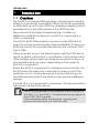
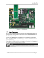
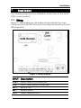
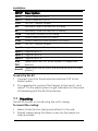
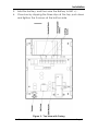
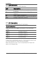
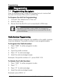
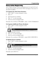
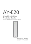
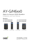
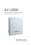
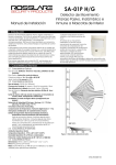
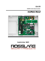
SA-59
GSM Communicator
Installation Manual
September 2009
Table of Contents
Table of Contents
1. Introduction ......................................................................... 3
1.1 Overview .......................................................................... 3
1.2 Main Features .................................................................. 4
2. Technical Specifications ....................................................... 5
3. Installation ......................................................................... 6
3.1 Wiring ............................................................................. 6
3.2 Mounting ......................................................................... 7
3.3 LED Indicators: ................................................................. 9
3.4 I/O Description ................................................................. 9
4. Messaging Types ................................................................ 10
4.1 SMS Messaging Types .................................................... 10
5. Programming ..................................................................... 11
5.1 Programming the system ............................................... 11
Prefix Number Programming ......................................... 11
Phone number Programming ....................................... 12
Appendix A.
Limited Warranty ............................................. 13
Appendix B.
Technical Support ............................................ 15
SA-59 Installation and User Manual
Page ii
Introduction
1.
Introduction
1.1 Overview
The SA-59 is a universal GSM reporting unit and communicator.
When it is connected to an Alarm Panel, the SA-59 operates as
a GSM back-up unit to the PSTN line, enabling outgoing calls to
be redirected to the GSM network if the PSTN line fails.
Since the SA-59 simulates a telephone line, it makes no
difference whether the device to which it is connected is a
GSM or a land line.
The built-in SA-59 GSM module connects via the PSTN line to
check for phone communication type availability. If there is no
PSTN line, the SA-59 automatically switches the call from PSTN
line to GSM.
When an event occurs, the Alarm System calls the PSTN line to
report an Alarm. Instructions to arm/disarm, check sensors and
other facilities of the system are relayed via system codes or a
phone-pad and voice menu, depending on the system to
which it is connected.
When the SA-59 is connected to a telephone line (Line IN), the
SA-59 tunnels the device to a land line to make a call. If the
land line is cut or not functioning, all communications go via
the GSM network without the need for any special additional
settings.
If the SA-59 is not connected to a land line, all communications
take place via the GSM network.
Note:
The SA-59 incorporates a SIM interface, which conforms to
the GSM 11.11 and GSM 11.12 standards that are based on
the ISO/IEC 7816 standard.
These standards define the electrical, signaling and
protocol specifications of a GSM SIM card.
Page 3
SA-59 Installation and User Manual
Introduction
Figure 1: GSM Module
1.2 Main Features
SA-59 uses GSM standard to backup the hardwired telephone
line (PSTN) in case where PSTN line is cut or tampered with on
the alarm panel side.
The SA-59 has a battery charger and a space for Rosslare’s
BT-16, 12V DC / 2000 mAh NiMH type - Nickel-Metal Hydridea
backup battery.
There are 4 inputs in which a change in the input voltage level
will change the corresponding output.
Note:
Where 0 is connection to ground and 1 is has infinite
impedance.
SA-59 Installation and User Manual
Page 4
Technical Specifications
2.
Technical Specifications
Electronic Specifications
Voltage
14v/2A
Maximum Power
Consumption
1.2A, when power supply is 14V
Standby Current
0.2A, when power supply is 14V
Battery
Option for Backup Battery of up to
12VDC/7Ah and local charger for
the battery
Connector Output
3 Open Collector outputs of 200mA
Relay
1 Form-C 1A relay related to Input 1
Telephone Lines
Telephone line-out and telephone
line-in
LEDs
5 LED indications (see Figure 2).
Connections
PSTN Telephone Line-IN Connected to the main telephone
line in the premises before any
other connection
Telephone Line-OUT
Should be connected to the alarm
system
Environmental Characteristics
Operating Temp.
0˚c to 60˚c (32˚F to 140˚F)
Operating Humidity
0 – 95% Non-Condensing
Dimensions
Height x Width x Depth
162 x 223 x 35 mm
(6.38 x 8.78 x 1.38 inch)
Weight
Page 5
435 g (1 lbs.)
SA-59 Installation and User Manual
Installation
3.
Installation
The following represent the installation instructions of the SA-59
GSM communicator.
3.1 Wiring
Figure 2: Wiring diagram, describes schematically the main
components on the SA-59 board, including terminal blocks and
LED indicators.
Figure 2: Wiring diagram
INPUT
Description
V IN +
Input Power Plus Connection
V IN -
Input Power Minus Connection
BAT +
Battery Plus
BAT -
Battery Minus
OUT 1
Open collector Out 1
SA-59 Installation and User Manual
Page 6
Installation
INPUT
Description
OUT 2
Open collector Out 2
OUT 3
Open collector Out 3
+12V
12V DC, 100ma, output
NO
Normally Open connection of Relay
NC
Normally Close connection of Relay
COM
Common connection of Relay
L Off
Open collector line off output
G Off
Open collector GSM module off output
+12V
12V DC, 100ma, output
Input 1 Logical input 1 / Tamper input
Input 2 Logical input 2
Input 3 Logical input 3
Input 4 Logical input 4
Line
OUT
Telephone Line OUT (from system to telephone
device)
Line IN
Telephone Line IN (from the entrance point to the
system)
To wire the SA-59:
1. Connect Line IN to the phone line and Line OUT to the
Alarm System.
2. It is suggested to connect the Tamper to the Input 1 and
output 1 to the alarm system to get indication on the event
of tampering with the SA-59 enclosure.
3.2 Mounting
The SA-59 mounts on a wall using the unit’s casing.
To mount the casing:
1. Make 4 holes for the casing and attach to the wall.
2. Thread cables along the back cover into the panel via
holes provided.
Page 7
SA-59 Installation and User Manual
Installation
3. Add the battery, and then wire the Battery to BAT +/-.
4. Close box by clipping the three clips at the top, push down
and tighten the 3 screws at the bottom side.
Figure 3: Top-View with Casing
SA-59 Installation and User Manual
Page 8
Installation
3.3 LED Indicators:
The table below shows the LED indicators
LED
Description
LD1
GSM Power ON –Power supply is connected
to device
Transmission – Transmission of signal to
antenna
Reset – Reset in power up
GSM Power-Up Ready – Power up the device
Dialing –Telephone / Device
D3
D4
D1
LD21
3.4 I/O Description
The table below describes the I/O activation
Input Activation
Input activation will trigger the outputs, in the following
order:
Input 1
Activate Output 1
Input 2
Activate Output 2
Input 3
Activate Output 3
Input 4
Activate Relay
Outputs are controlled by inputs, so that when the Input is set
to 0 (Grounded) the Output will be activated.
When the Input is set to 1 (not connected) the Output will
return to its steady state.
Page 9
SA-59 Installation and User Manual
Messaging Types
4.
Messaging Types
There are a number of recognizable SMS message types which
the system sends to preprogrammed phone numbers. The
system memory holds 4 telephone numbers enabling
messaging and notification to relevant parties when the Alarm
System is violated. All SMS’s are controlled by changing the 4th
input in the SA-59.
4.1 SMS Messaging Types
Input
Sent Message
Input 1 high:
Input 1 low:
Input 2 high:
Input 2 low:
Input 3 high:
Input 3 low:
Input 4 high:
"SYSTEM TROUBLE"
"SYSTEM TROUBLE RESTORE"
"SYSTEM ALARM"
"SYSTEM ALARM RESTORE"
"SYSTEM ARMED"
"SYSTEM DISARMED"
"PANIC ALERT"
Note:
When system indicates “SYSTEM TROUBLE” The input
switched from 0v (connected to ground) to a not
connected state (tri-state or high impedance).
Note:
When system indicates “SYSTEM TROUBLE RESTORE”
The input switched from a not connected state to 0v
(connected to ground).
SA-59 Installation and User Manual
Page 10
Programming
5.
Programming
5.1 Programming the system
Prior to programming, make sure a telephone is connected
but do not connect the unit to a PSTN line.
To Prepare the Unit for Programming:
1. Connect the telephone to "line out".
2. Wait for dial tone.
3. Ensure that the SA-59 is not connected to PSTN lines.
Note:
The default installer code is 5555. To change the
default installer code see Do not connect the SA-59
to the PSTN lines.
Prefix Number Programming
When using the GSM network, the addition of a prefix number
may be needed. The prefix number is user programmable.
To Program the Prefix Number:
1. Press “5555” to enter program mode.
2. Press “1”.
3. Type the prefix number.
4. Press “#” to acknowledge.
5. Hear the acknowledge beeps.
Example: the prefix number is 9 – press 5555 1 9#
To Delete the Prefix Number:
1. Press “5555” to enter program mode.
2. Press “1”.
3. Press “#” to acknowledge.
4. Hear the acknowledge beeps
Example: press 5555 1 #
Page 11
SA-59 Installation and User Manual
Programming
Phone number Programming
Up to three numbers can be programmed into the SA-59 unit,
to which the system will send an SMS message in the event of
an event or alarm.
To Program the First Phone Number:
1. Press “5555” to enter program mode.
2. Press “2”.
3. Type the phone number.
4. Press “#” to acknowledge.
5. Hear the acknowledge beeps.
Example: the number is 052646666 – press – 5555 2 052646666 #
To Program Additional Phone Numbers:
1. Press “5555” to enter program mode.
2. Press “3”.
Note:
For the third phone number Press “4” instead of “3”.
3. Type the prefix number.
4. Press “#” to acknowledge.
5. Hear the acknowledge beeps.
Example: the number is 052525222 – press 5555 3 052525222 #
To Delete Phone numbers:
1. Press “5555” to enter program mode.
2. Press “2”.
Note:
To delete the next number Press the next
consecutive number.
3. Press “#” to acknowledge.
4. Hear the acknowledge beeps.
Example: press 5555 2 #
SA-59 Installation and User Manual
Page 12
Limited Warranty
Appendix A.
Limited Warranty
ROSSLARE ENTERPRISES LIMITED (Rosslare) TWO YEARS LIMITED
WARRANTY is applicable worldwide. This warranty supersedes any other warranty.
Rosslare's TWO YEARS LIMITED WARRANTY is subject to the following conditions:
Warranty
Warranty of Rosslare's products extends to the original purchaser (Customer) of the
Rosslare product and is not transferable.
Products Covered By This Warranty and Duration
ROSSLARE ENTERPRISES LTD. AND / OR SUBSIDIARIES (ROSSLARE) warrants
that the SA-59 Universal GSM Reporting Unit, to be free from defects in materials and
assembly in the course of normal use and service.
The warranty period commences with the date of shipment to the original purchaser
and extends for a period of 2 years (24 Months).
Warranty Remedy Coverage
In the event of a breach of warranty, ROSSLARE will credit Customer with the price of
the Product paid by Customer, provided that the warranty claim is delivered to
ROSSLARE by the Customer during the warranty period in accordance with the terms
of this warranty. Unless otherwise requested by ROSSLARE ENTERPRISES LTD.
AND / OR SUBSIDIARIES representative, return of the failed product(s) is not
immediately required.
If ROSSLARE has not contacted the Customer within a sixty (60) day holding period
following the delivery of the warranty claim, Customer will not be required to return the
failed product(s). All returned Product(s), as may be requested at ROSSLARE
ENTERPRISES LTD. AND /OR SUBSIDIARY’S sole discretion, shall become the
property of ROSSLARE ENTERPRISES LTD. AND /OR SUBSIDIARIES.
To exercise the warranty, the user must contact Rosslare Enterprises Ltd. to obtain an
RMA number after which, the product must be returned to the Manufacturer freight
prepaid and insured
In the event ROSSLARE chooses to perform a product evaluation within the sixty (60)
day holding period and no defect is found, a minimum US$ 50.00 or equivalent charge
will be applied to each Product for labor required in the evaluation.
Rosslare will repair or replace, at its discretion, any product that under normal
conditions of use and service proves to be defective in material or workmanship. No
charge will be applied for labor or parts with respect to defects covered by this
warranty, provided that the work is done by Rosslare or a Rosslare authorized service
center.
Page 13
SA-59 Installation and User Manual
Limited Warranty
Exclusions and Limitations
ROSSLARE shall not be responsible or liable for any damage or loss resulting from
the operation or performance of any Product or any systems in which a Product is
incorporated. This warranty shall not extend to any ancillary equipment not furnished
by ROSSLARE, which is attached to or used in conjunction with a Product, nor to any
Product that is used with any ancillary equipment, which is not furnished by
ROSSLARE.
This warranty does not cover expenses incurred in the transportation, freight cost to
the repair center, removal or reinstallation of the product, whether or not proven
defective.
Specifically excluded from this warranty are any failures resulting from Customer's
improper testing, operation, installation, or damage resulting from use of the Product
in other than its normal and customary manner, or any maintenance, modification,
alteration, or adjustment or any type of abuse, neglect, accident, misuse, improper
operation, normal wear, defects or damage due to lightning or other electrical
discharge. This warranty does not cover repair or replacement where normal use has
exhausted the life of a part or instrument, or any modification or abuse of, or
tampering with, the Product if Product disassembled or repaired in such a manner as
to adversely affect performance or prevent adequate inspection and testing to verify
any warranty claim.
ROSSLARE does not warrant the installation, maintenance, or service of the Product.
Service life of the product is dependent upon the care it receives and the conditions
under which it has to operate.
In no event shall Rosslare be liable for incidental or consequential damages.
Limited Warranty Terms
This warranty sets forth the full extent of rosslare enterprises ltd. and it’s subsidiaries’s
warranty
The terms of this warranty may not be varied by any person, whether or not purporting
to represent or act on behalf of rosslare.
This limited warranty is provided in lieu of all other warranties. all other warranties
expressed or implied, including without limitation, implied warranties of merchantability
and fitness for a particular purpose, are specifically excluded.
in no event shall rosslare be liable for damages in excess of the purchase price of the
product, or for any other incidental, consequential or special damages, including but
not limited to loss of use, loss of time, commercial loss, inconvenience, and loss of
profits, arising out of the installation, use, or inability to use such product, to the fullest
extent that any such loss or damage may be disclaimed by law.
This warranty shall become null and void in the event of a violation of the provisions of
this limited warranty.
SA-59 Installation and User Manual
Page 14
Technical Support
Appendix B.
Technical Support
Asia Pacific, Middle East, Africa
Rosslare Security Products Headquarters
905-912 Wing Fat Industrial Bldg,
12 Wang Tai Road,
Kowloon Bay Hong Kong
Tel: +852 2795-5630
Fax: +852 2795-1508
E-mail: [email protected]
United States and Canada
1600 Hart Court, Suite 103
Southlake, TX, USA 76092
Toll Free:+1-866-632-1101
Local:+1-817-305-0006
Fax: +1-817-305-0069
E-mail: [email protected]
Europe
Global Technical Support & Training Center
HaMelecha 22
Rosh HaAyin, Israel 48091
Tel: +972 3 938-6838
Fax: +972 3 938-6830
E-mail: [email protected]
South America
Pringles 868, 1640 Martinez
Buenos Aires
Argentina
Tel: +54 11 4798-0095
Fax: +54 11 4798-2228
E-mail: [email protected]
Web Site: www.rosslaresecurity.com
Page 15
SA-59 Installation and User Manual
0706-0960294+00
WWW.ROSSLARESECURITY.COM