1
Cable Testing
Motor and Generator Testing
Transformers are tested at or above the rated voltage to
be certain there are no excessive leakage paths to ground
or between windings. These are conducted with the
transformer completely disconnected from the line and
load. However, the case ground should not be removed.
Before testing the above lift the rotor brushes, ground the
starter terminal and frame and ground the motor shaft.
Discharge the field winding by grounding. Then remove
the field winding from ground and connect to the (-) Line
connection on the megohmmeter. Connect the (+) Earth
terminal to ground. The diagram shows the connection for
testing the field insulation resistance. The stator winding
may also be measured in a similar manner.
Single Conductor
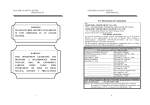
Connect as shown in the diagram
a. Conductor to Line (-) terminal and sheath to Earth (+)
Multi-Conductor
a. Single conductor
b. One conductor to all
c. One conductor to earth
d. One conductor to others minus ground
Stator
T4
T1
Insulation
T5
T2
T6
T3
N
Conductor
ƒ1
ƒ2
Field
Ground Sheath – single conductor
a. Single conductor
Three-conductor
cable
b. One conductor to all
= Earth Terminal
= Line Terminal
G = Guard Terminal
© 2002 Chauvin Arnoux®, Inc. d.b.a. AEMC ® Instruments
c. One conductor to earth
Three-conductor
cable
d. One conductor to others minus ground
Understanding Insulation Resistance Testing (pdf) 02/06 Rev. 02
Technical Assistance (800) 343-1391
5 of 6