1
48784
11
$2.50 U.S.
$2.95 CANADA
FEBRUARY
1
?88
THE MAGAZINE FOR THE ELECTRONICS ACTIVIST!
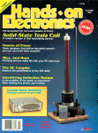
The
Power Play
;
_ )0.
ON
410
Two power supplies in one
case with digital readout
for voltage or current.
OFF
NE G
!
SIDEC
um.- NI
UTILITIES
Put your home computer
in overdrive! We cover
PIS1110
PICT
EDITOR
NERI
-
the most powerful
packages available.
.K/TREE
POI /PIOC
TIMIIIY011
LETTERS
.
REPLIES
ÈUQIOIE
GOV..
11
I
I/N/
MII71
p1
177721
7175
7772
191577
1117
11151111101
SPL
LONG
AL?
PRINT
mP
SERIAI
STARVI
MT
Vol
I17
TIOVE-1
11
YEK
0111
041
UI/.
U.rr Isles
2101111 1,1t..
SPL
INt
kort .,Ad
1.lrt tOt1
t
IT,11. bytes ..r1
455768 19t.. fetal
22172
112
...Niel
IIIIS
725152
22711
1.
...
Ldlri1 11
3M
1:16..
11.,1.1
ACTION
PERSONAL
-
cow
Ente
I TYP.
SHIERS
,r
-
-
-
C
rat
110.
I
=PMdEwa MI
C...
OUI,
11(0115
11.1
V1[
(..1_.u1..I01l.I lrt 1..
Set
WIND WITCHER
11J
T1 .r.M..l Doi On
.r
<.y.l4l.
<t1.
t011
tinkles without motion
..1
011ry ,01
V1. S..<1.1
/rot. (.M
Prut fete
0.01
it Prr..ltuY.N
ti01
lee
.. IF".
pot. Tl.. 0.01 1..1yI.M 1!... ..I.tN
r1 .<1.,t .Y 1r 01
.1t1
11
Ir
(.L.
2747,1,11
15,27113,01
27,/Y21M4
274141,1
27,71444
DISH POSITIONER
TVRO remote move -it plans
27045,144
2704(711,1
.r..
1111 111111011
w.1I.,r4
1.1 I ,TINT
AUDIO SWITCHBOX
inputs
try
(...
(
-5 outputs
1
-
11101
Ws
11. 11M
1-rl.lnle
5-b.1nn.
-01lwW W
1
1.4..
V
1
0
I
1r
T.
<1....
14..
I.tr..n.t
11 I I.r
1t 01
1[S(1
t.11.1 III.
I...
-
- Iambs
...1
ELt.rrd.
lbw lil.
1-Lrl.i
11 P.11,
-
l- Ley /Wale - Ts= l...,
l- diesel
-IN.,I..
-Ltl.tl
NNW
P
/
-
..1w..a.
1- It.m hie
I - S,..l
T
- TN 111t
1- Fete Ills
t. INAtr.1 111t
8
r
I- Wale /Ile 1-MI.<I...
02
71896 48784
ht.
C.
Auno
-
Unknown Ls to Henrys
5
L«l;l lit
A.
17511y~r1
N
Plus
INDUCTANCE BRIDGE
It
11.11
:Ia
25717
MI
Atli
SPELL
1
ERI
711KIS2 PIP
(OPIMI (On
.111
-
Lut
t..
..
..les IJ.r
1111[-.1111 1lY
-
Ll.r.
,11..w
1,
M1.<.t...
.ns. 44...a .r.t. 4117
_+GERNSBACK
1.01
I
T.
nformatìon
radio is on
the air.
Before you hear about
Hear Your Hometown Like
You've Never Heard it Before.
it on your old
radio, hear it
live on your
new Informant Information Radio.
Whether its an all- pointsbulletin from the State Police,
the dispatcher for the city's Fire
Department, an ambulance racing
to the hospital or a National Weather Service report, the new Informant from Regency makes you a
part of all the action... instantly.
Breakthrough Technology.
Instant Information.
Informant Information Radio
uses a revolutionary new technology that allows you to constantly
monitor your police, fire and
Just turn it on. As easy to use
as your AM/FM radio. Instantly,
you're tuned into real life adventures. One touch control lets you
emergency frequencies, select and hold police, fire and
as well as NOAA weather in- emergency broadcasts so you don't
formation channels in all 50
miss a single minute of the action.
states. All pre- programmed. This
Hear the amazing Information
new Information Radio utilizes a Radio today. Take it home and be
principle similar to the seek
a part of the action tonight!!
and scan feature found on
expensive AM/FM radios.
Your information radio
l
scans the public service
.11V
T
1
BY REGENCY
channels in the area, locates
the active signals, locks in and
Information Radio
broadcasts all the information
Real Life
for
right to you. With revolutionary
TURBO-SCAN speed!
Adventure
ORM.RNI
CIRCLE 10 ON FREE INFORMATION CARD
ahn
cs
Volume 5, No.
FEBRUARY 1988
2
CONSTRUCTION
31
Remote TVRO Dish Positioner -puts the focal point of your satellite dish
where you want it for maximum signal strength
Maxwell Inductance Bridge -determine the exact value of inductance with
35
Power Play -put this power supply on your workbench, and you'll need no
40
Wind Witcher- Listen to mother nature's gentle song with this hot -wire
sensor electronic chime
5 x 5 Audio Switch Box -eliminate the rat's nest of interconnecting wires
hidden behind your stereo equipment
26
this project
4-
other!
43
NRO Dish Positioner-page
26
111j,_,Litate'
FEATURES
59
Identifying Unmarked or Obscurely Marked Logic Chips -make use of
65
Getting Your FCC Radio -telephone License-what you need to know to
69
legally get your own license
E -Z Math -Scientific Notation and Unit Conversions: clearing up milli,
micro, kilo, Meg, etc. with powers
those otherwise useless logic devices
Maxwell Inductance Bridge-page
aim.
l
J
HANDS -ON REPORTS
34
49
61
Date Calculation Software -gives the day of the week that a particular
date has fallen, or will fall, on
Utility Software -Utilities are what make newcomers to personal
computing appear like old hackers
Bytesize Calc -an on- screen calculator for those times when all the frills
aren't needed
,.
-
J
..
11
ll
31
I
4---1-____:),4:i.:
Power Play-page 35
SPECIAL COLUMNS
74
76
Ellis On Antique Radio -Firing up the Crosley 50
Circuit Circus- Produce the most -basic building -block circuits from
78
80
84
87
88
inexpensive op -amps
Carr On Ham Radio -Why's my dial all scrunched up while yours isn't?
Friedman On Computers
takes no space to tick away the time
Wels' Think Tank -What to do with number two?
scanner with a flair for the weather
Saxon On Scanners
Jensen On DX'ing -Say goodbye to that 1987 calendar
4
8
17
40
-lt
-A
DEPARTMENTS
2
-fie
Wind Witcher
x 5 Audio Switch Box -page 43
Editorial -The HOE PC give -away; the votes have been tallied and the
winner rewarded
Letter Box -where readers get involved and make things happen
New Product Showcase-where you'll find stocking -stuffers for the
technically oriented
Bookshelf -take a look what's new in easy -to -read electronic reference
and data books
37
63
FactCards -the component data and applications at your fingertips
Free Information Card -why waste time ?; let the manufacturer clue you in
Saxon On Scanners-page 87
1
L
Volume 5, No. 2
February 1988
The Magazine for the Electronics Activist!
Larry Steckler, EHF. CET
Editor-In -Chief 8 Publisher
Art Kleiman, editorial director
Julian S. Martin, KA2GUN, editor
Robert A. Young, associate editor
Herb Friedman, W2ZLF. associate editor
John J. Yacono, associate editor
Brian C. Fenton, associate editor
Carl Laron, WB' SLR. associate editor
Byron G. Wels, is2AVB, associate editor
M. Harvey Gernsback, contributing editor
Doris Kelly, assistant editor
Teri Scaduto, editorial assistant
The winner is....
...Walter W. Schopp of Livermore,
California for his construction article
"Digi -lyzer IC Tester" that appeared in
the August, 1987 issue of Hands -on
Electronics. The Digi -lyzer offers
rapid IC checking of most logic -type
IC's available to the experimenter.
For those of you who do not recall,
Schopp's Digi-Iyzer
ran a contest for the best
article published in this magazine in 1987. The prize is an IBM
compatible computer, which we have shipped to the winner and
he is probably playing with it now.
I
Lets do it again....
Ruby M. Yee, production director
Karen S. Tucker, production manager
Robert A. W. Lowndes, editorial
associate
Marcella Amoroso, production assistant
Jacqueline P. Cheeseboro, circulation director
Arline R. Fishman, advertising director
BUSINESS AND EDITORIAL OFFICES
...and offer another computer. Why a computer? You have seen
the advertisements, especially those on television, that say that
report writing for school and office is simpler and has improved
the potential of the individual using a computer. This is also true
for the professional and amateur writer. Word processing programs, spelling checkers, thesaurus, and other writing aids such
as simple desk -top publishing programs are must items for
writers today.
Gernsback Publications. Inc.
500 -B BI -County Boulevard
Farmingdale, NY 11735.
516 293 -3000
President: Larry Steckler
Vice -president: Cathy Steckler
NATIONAL ADVERTISING SALES
(For Advertising Inquiries Only)
Joe Shere MIDWEST/PACIFIC
1507 Bonnie Doone Terrace
Corona Del Mar. CA 92625
714 760 -8697
So get busy....
...and start producing those exciting manuscripts about features
and projects that are related to our exciting hobby. The topics
come easy. For example, there are topics on shortwave listening,
project building, scientific developments, amateur radio, computers and software, scanners, television, satellites, odd -ball
semiconductors....I could go on and on. But, if do, and go
beyond this editorial page, I'll be entering the contest.
The Paths Group
310 Madison Ave. Suite 1804
New York. NY 10017
712- 953 -2121
.,omposition by
Mates Graphics
I
...and maybe I'll be announcing your name next year in the
February issue. You can make it so if you begin today!
')
Herb Friedman
®
AIA
Start writing today....
Cover photography by
Hanson Electronics,
(ISSN 0703.29881 Published monthly by
Gernsback Publications. Inc 500-B Bi-County Boulevard. Farm
tngdale. NY 11735 Second-Class postage paid at Farmingdale, NY
and at additional mailing offices One-year. twelve issues subscripbon rate U S and possessions $28 00 Canada $33 00. all other
countries $35 50 Subscription orders payable to U S funds only
International Postal Money Order or check drawn on a U S bank
U S single copy pone $2 50 c 1988 by Gernsback Publications.
Inc All rights reserved Trademark registered in U S and Canada
Ponied to U 5 A
Postmaster
Please send address changes to Hands -On ElecPO Bo. 338 Mount Morris IL
tronics, Subscnphon Dept
61050.9932
stamped sell addressed envelope must accompany all submitted
manuscripts and or artwork or photographs d their return is desired
should they be rejected We disclaim any responsibility for the loss
or damage of manuscripts and or artwork or photographs while in
our possession or otherwise
A
Julian S. Martin, KA2GUN
Editor
As a service to readers Hands-on Electronics publishes available
plans or information relating to newsworthy products techniques
and scientific and technological developments Becatse of possible variances in the quality and condition of materials and workmanship used by readers. Hands -on Electronics dI,claims any
responsibility for the sale and proper functioning of readenbuill
projects based upon or from plans or information published in this
maoa,ne
2
SELECT 5 BOOKS
CIC)LLLESHOOTING AND
REPAIRING
SOLID-STATE TVS
7
'Clt
'
for only $3.95
J
(values to $127.70)
'tt
jlrtj%and get a Free Gift.
`
',/10,
Icon ic
1
1199P
Ná1110140
'"
30 CUSTOMIZED
OPROCESSOR
MIC PROJECTS
NOM IC
AEPA.N
G
" IROUBlE51100I
ELECIALIAC CIRCUITS
\lllill.
-v
S15.95
I.lil-
BUDGET
.
ABizair
1503P
515.95
RECOitüi
-
2707 $26.95
Counts as 2
MASTER
2635
-.
1111111.11L'._
-
519.95
2936
514.95
24
'
DEdCN ANO
BUILD
ELECTRONIC
SILICON-C NTR0LLEO
RECTIFIER PROJECTS
INSTRI MEYImTDM
2733
314.95
1218P
514.95
2705H
$22.95
Electronics projects ... ideas ... the latest technology
all at up to 50% off publishers' prices
Membership Benefits Big Savings. In addition to this introductory
1599P
516.95
800P
519.95
CrliC)
ua
1
rlvi)
.Y11i1
CN
278-1
518.95
1593P
A time- and money- saving list
of product literature from all
the major electronics suppliers.
fa St; .9
4.1104 oro
E&TAONC PROEM
ELECTROSTIC
LOUDSPEAKER
hiss
Or9LN
w
AND
517.95
r
i
1
$14.95
I1M 11111t1,
....II
Reference (;uide
to Elect rooks
Manufacturers' Publications
TROUELESHOOTIk6
2
1586
1\1111\114
Reference Guide to Electronics
DIGITAL
525.95
1625P
FREE when you join!
58.95
Counts as
517 95
offer, you keep saving substantially with members' prices of up to 50% off the
Bonus Books. Starting immediately, you will be eligible for
publishers' prices.
Club
our Bonus Book Plan, with savings of up to 80% off publishers' prices.
News Bulletins. 14 times per year you will receive the Book Club News, describing all the current selections- mains, alternates, extras -plus bonus offers and
Automatic Order. If you
special sales, with hundreds of titles to choose from.
want the Main Selection, do nothing and it will be sent to you automatically. If
you prefer another selection, or no books at all, simply indicate your choice on
the reply form provided. As a member, you agree to purchase at least 3 books
Ironclad
within the next 12 months and may resign at any time thereafter.
No -Risk Guarantee. If not satisfied with your books, return them within 10 days
without obligation!
Exceptional Quality. All books are quality publishers'
(Publishers' Prices Shown)
editions especially selected by our Editorial Board.
ELECTRONICS
2750
2660P
nIDE'f
11111,
1u,11i1
NanufaclurerN'
l'o bliralions
1160P
ELECTMINCSEaaKCLUB
J
Blue Ridge Summit. PA 17294 -0810
Please accept my membership n the Electronics Book Club' and send the
volumes listed below, plus my FREE copy of Reference Guide to Electronics
Manufacturers' Publications (2683P). billing me $3.95 plus shipping and handling
charges. If not satisfied. may return the books within ten days without obligation
and have my membership canceled. agree to purchase at least 3 books at regular Club prices (plus shipping /handling) during the next 12 months, and may
resign any time thereafter.
1583P
510.95
513.50
HIËÁDÌB6
SCHEMATICS
I
I
111
.49EP
511 95
2832
1536P
$23.95
114011GaóAa.4M%
semen.
I
_1
ELECTRONIC
TEST EpL'1P118fAT
2609P 516.95
$8.95
ROBOT BUILDER'S
BO \A\ZA
se INIXPPNSn'L
ROBOTICS
Name
PR
Address
?tf
2922
574 9S
1663P
517.95
City
--
State/Zip
_
Phone
_
Valid for new members only Foreign applicants will receive special ordering Instructions Ganad,
must remit in U S currency This order subject to acceptance by the Electronics Book Club
RESP -288
..
n bers are followed
..,aperback
All books are hardco°
,
.......
.
CIRCLE 12 ON FREE INFORMATION CARD
`-2795
-
529.95
Counts as
2800
523.95
2
3
L
iL J
D
D)
1
D
Hands -on Electronics, 500B Bi-County Boulevard, Farmingdale, New York 11735
No Critic Here
subscribe to a number magazines,
ranging from Consumer Reports to Science (the journal of the American Academy for the Advancement of Science).
Frankly. Hands -on Electronics is turning out to be one of the ones I most enjoy
receiving. I just got the November issue
and for some reason decided to write and
say, "You people are doing a great job."
Beautiful and extremely useful magazine, more like an investment than a
subscription.
-R.A., Otter Rock. OR
I
Thanksfor the kind words of praise.
There is something wrong with your letter. though: it's all praise. We at Hands on Electronics want complaints too.
We are in a wonderful situation here;
we get to distribute information on our
hobby. Almost all of us here are hob byists just like you, and we want to pro duce a magazine that we would spend
our own hard-earned bucks for. Many
readers like yourself tell us we do just
that, but complain a little more and
maybe are can out -do ourselves!
Washed Out
self-service carwash, out of which I get much enjoyment. A few months ago, after my dollar
bill changer was broken into, I decided
that it was time for a steel plate over the
changer and a burglar alarm to boot.
Looking through some of your older
magazines, I decided on the Dick -Smith
alarm (featured on pages 62-65, of the
work if the green lead is connected to the
collector of QI and the white lead to
ground.
The ASA setting for some of the the
switch positions are also wrong. The
positions for R8Rl3 should correspond
to ASA settings of 64, 100, 125, 200,
400, and 800, respectively. According
to the Parts List, the values of R12R14
should be 10K, 5K, and 5K, respectively. Also, the value of R6 (27K) is not
given on the schematic diagram.
Shouldn't the power switch (mistakenly labeled Si and not S2) be between the battery (drawn as a capacitor)
and the rest of the circuit?
I made all the above changes in the
circuit and got it to work fine, so I think
the answer to all my questions is "yes."
Thanks for giving me a project to cover
both my hobbies.
-S.S., Idleburg, PA
I own and operate a
January/February, 1986 issue).
I purchased the kit from Dick -Smith
and built a 12 -Volt DC power supply
from Radio Shack parts. It worked great
on the bench! After all of the guts were
mounted in a box and the installation
complete inside the pump house it
doesn't work properly. I have tried several basic fixes, but being the novice that
I am, I still can't get my act together.
When the unit is switched on it triggers itself 50% of the time. Dick -Smith
recommends that a 331LF or 471.LF capacitor be soldered across the supply rail
of the 555 timer to prevent this, well
helped some, but not completely.
Another problem (or maybe part of
the first problem) is that fluorescent light
You're more than welcome, and you
are correct in all you say. Just so our
other readers know what we're talking
about, here's a revised schematic with
all the corrections. Thanks for the help.
-it
Idle Hands
if you had some kind
could build with my
hands like the one the man is doing in
the enclosed picture. I need that kind of
training, not just a book. Books do help,
but need some projects too. If you can
help me with this it would help me more
in the field of electronics.
-D. B.. Los Angeles, CA
I
was wondering
of project that
NC
GRN
I
e
01
02
1
The photo you sent us was from one of
our advertisements. You know how to
write us so why are you holding out?
Subscribe. Look at this issue, it's loaded
with projects: nulf said.
10
R7
BASE
DIAGRAMS
R2
2
eÇc
25K
R6
4
R9
2 N 697
dVsub
02
0
25K
R
1
25K
R12
R13
410K 45K
tR14
7K
5K
o0
y
2
125
O
200
0400
800
0 1000
0
q
s
R
425K _1 25K
100
O1
In the November issue, concerning
the article on the Flashmate, the miniature output transformer has one lead
that is not connected. Not the NC lead
but the one below it. Where does it go
to? Further. doesn't the polarity of the
transformer matter'! I found the unit will
S1
RESET
6
Picture Perfect
sub
q
I
C1
R6
S3
27K
ASA
R3
M1
200ft
O
S2
PO WER
0 -50
MA OC
1
R5
2K
2
R4
2000
81
1
5
O
______=
- _ -_
_
C
`
1-800 -344-4539
im 1m
IM
P O
R
O
ON /
.
A
R
^Fv
OKMACHINÉMEWC INC. ONTERSILAD
EAC. INC. J. W. MILLER AAVID ENG NEI
E F. JOHNSON *ATLANTIC SEMICONDUC'
VISA
/
AK, Puerto Rico
256K (262,144
-
T.
21131181-0074
FAX
..127114
DRAM 150NS $5.7011; $39.95I9 ESDCWINDUSTRESÁMDEKGRE.
x 1)
Factory
EY Firsts
-
t
INTEGRATED CIRCUITS
I
400
7
3
WOO
,..
..r
SOLDER TAIL
DIP SOCKETS
-
.
.r
..
cMDS
.
ánCwrc
rev
..
.
.
.
-
-
,
'
=1
llll
-.
1
we
4.00
r
AN
I
y
S2
4 46
37 22
67
4 61
M
} a=
7
.7..
n
e a
n-.
Nway11a
.
m
rAa
V
0
r n wm..
..
71
3
A
.
^
rr
.
.
osx
PLOY
"
r
A.r
m..n
.. .
611
30
u
15
ya
s
cad
IA
1111
1
..
333104.
aa
no
..
a
Á
..
M1
e
OM
.1......
I
41113
M
.Y
CO
m9rm
sY
io 97.7
YE
6
P<s7..a
0.1.04
m.noloPYrlw9
a.T
7
MA
..7.r
/naor
H
Sty Ma
seo
.vmw
6
MS,
304001
17,01VY.4.
-
./n...,
NEC
1
aa
^vs1
=
I
034
-fL
11N
M1
s«.
n
o...
C
MAW
axe
"C1
'
..
111.r.cis9úxcN...
.°e.r.."m.....911.
NTérr
9
áo°°.
mo.
¡CO;
:
19.
1
.
_
*mom
Fe.
mr1m v
,.orco...
r1..
.....
h
CA
9
IS
SO
CO
Cle
06
In
y.
M m
In sr
ro
CO
.
CM
85
a..
9. 5
no
)m on
w
r
m
1m
NO
ON
37
1
AM
26
41
7 61
230
SI1
0
la
07
No
7
03
-AN
13 CO
a mu
U,
Aa
ICY
ár06
2110
NI.
3346
4711
..
-
.
SO
A.
SO
16
ç``'
er.w..ra...r..,
1r
11sm
`
V
.,1e
..
ac.
e..rr. A..ue WIN YAW of
rry..wC..rb.. ICY
AMAMI.
yq,r
..
Y..+1
ryYkMrv
!m
7.r=
w
SAM
10
1
;1
'
11
LIr
om
1O
SU
4
sai
.
........
A
,...
r
.
11
1
w1.s1r
07 le
ms10
m.
u.
r.
.,
m
rM.
.Arauru11
'
1
s
9
0001 9.99
10
00
125.00
25.00 -149.81
10.00181.81
0&ÚP
_
VI 70
_
A 1na
...
Car Na
oNrr
/3096
0
Add 82,00
Add 90.75
Add 90 50
Add 10.25
No Charge
4 77
sr
r6
es
Iav
SERVICE CHARGES
:
CIRCLE 8 ON FREE INFORMATION CARD
ar nw ma
n
.rcArAC1r0ys
mar
ill
A
b rs
wy.
......__.._,
17
N
;in
.
m
mral/
--
m
1
o._.N.:1:
w
rF1
M
no
e
..
'
..A..
1u
V SERIES
...
s........,,..1.,..
.1.
56
.. .
cATo 15495
PANASONIC
1
t
1
vA1u.
'
911 11711. IT NAIL UN TOW OROER TO. 11101119. P.O. Ia 171, MIR Rim NIA NE 19791.
ONEMS ST PNSE. CYL 1-SM 314 1131 IAN. call
YOU ny WY 1H cheC9. mary aar. Mql. CM1p., VISA or C U D D1Gr-NEP GUARANTEE. An. palls a P.o00cn IW ct1..a Isom D4 Key 1M aas m M 170I0014a wA b 1yl<.a WYO.
b0lrwMa.yNM190a.Y. from r.rasNr.mscepoly0wesas. pß«(5 SUIJECT TO CHANCE fl#051880S.
TRIES
13 73
m
g.
.n .
w
,
.,
iá
o.w ..o.....e.
IA.
-
Ìí
m..
1 11.1111 ON w rla dmanlMN ra denla. by IM uta.
T1r OqFK.y yaAI.INwawa aM rvks eyrl9r w/eoN m 900II Meyl i9wtr mid by DiP Iter may be coma./ s vMO...
ND Ia9P.rf
Pwy 1Master. A1lw w.blp ya,1 r0e1, tw.l M of ar dmOrMM11 aenn ma 9ePN 1M 0papin 00a,61 To 116., ,,o1w.l. 1100 tM II71.000406Utl9 aw1. TMn .aa 1M yervca
n IM U S A Cwuae ru Momo ul.w1 Clrcy or nloney aar w:conlp.1w wen D9
<Mp. W Py M 91wtMg end orwref in
ery Mom rdln.Mlln IS corn.. U S. Abe.
rarrsy. CrrOe and Me..o
4 OS
yam_
Ó
Ian
14 00
01
...
w
Fa,y
R..
22
V
áay
No
no
.
g mem
.
-- _t_
107
I
o°
V
. 9` .ae Ni
ÄÓ
.210
.Oá3
W
e
Y.
.
...
000.375-1:-il .000-{
1
1r 20
"
m7160
aM nr
em
16
e,ró; ®
sM.
I AMP SILICON REC11111 RS
Microprocessor Chips
DSO
7 13
ELI'
tA.
0440.44040. 60160.440
mu
w
04,
r0
....
10
.
111111111/
°..
®
Nmem
..wo.
Aa.
1
...
"
e
A
310
1a
7.
A
..
. i
..
..
en
NOV
8$
11
14111gni
11W21rS11W
rA.O°°s
y
170
.
.
r...
Sly
164
.
,
10
A
m11
000
2
in
N(
1é
66
..
f1
umroa
.
76
67
1
1p
'
:AND
rDNS
SC
ñ
Ú;
.
wo
..
CAT
)1
al
®
..-.
.
'.CmCMOS
-.
n
lrwerp
is
PANASONIC LS SERIES
22
sa
_-
AMY
r.i Ir
r
so
11601.nN6.1.1717
`
400
`
C'AwDISC
au
,
.iyi.l-'q:i1W-
I
,
.
meaner
i..
34
.......... noaiw.. ..a16YU
_
.,...
...
..
...
.
na.lwnw.u.w
n
1
.
mc
1a
LOON
a10900
1
wZ
...
w
y`
7»1
i
"
,
Metal Film Fused Resistors
y1
10
w
....1-
1710
.
1
A
R
s e.
710,710
.. 1.wr
r
.
uP
Way
000.4443
.
3 01
'
'
gd .
w
d e.nN.w.e.n..
,
..
..
.
4
_-
.. v
4ñ
CV
nt n.y9a
yN.l<.ewy..Arr
1`4..
y.
16
?.nse...r
,
r.0
11.ASw9u.roun
.
-
30 CO
nN.m
DIPSOCKETS
-
ASV
-
0464n1.4 1040.44400
WIRE WRAP
--
'
77
R
e
w
.
A TR
I
9n0
rerl
ae..r
i..
..
am..,.
>
1e)N
u, ae
.
.
t
^'
.ra..aa wlNyonY
1017.
r1
.r w
..
-
r
éi
á
.q
ru...
I
UM CAPACITORS
A1
T
Ñ
1
.."..
TAM
¡I
4GAR YAGEO J. W. MILLER LUXO
PLESSEY
ARIES
3C CHEMICALS
I
p
9103508982 CIGI KEY CORP
TWO
211 -811 3390
e
40 50
rsn
s
m
116
CO
moo
t7. cc
VOLUME DISCOUNT
9
9
9
9
0.009 99.19
924910
100 00
250 00
1499.!
500 00.9999.81
910009 Up
NET
19.110'/0
L9u 15'h
Less 20'7.
Less 25'
5
operation, pump motors, and changer
operation trigger the unit. Can you help
me? I have spent much time wiring the
bay money boxes, Coke machines, towel box, pump -house door, and bill
changer. I used all magnetic reed
switches. It's a beautiful installation; it
just doesn't work!
-J.W., Ashland AL
There are lots of things you could try.
First, put the trigger circuit in a metal
box to cut down the RF interference.
Second, try using shielded cable to all
your switches. Also, be sure your power
supply has a large output capacitor
across it (on the order of 1000 -µF), and
that it is well regulated. Last but not
least, try bringing the power supply voltage down to 9 volts. You may be providing too much current to the circuit
making it unstable in it's new RF-filled
environment.
Hooked
I have been reading your publication
now since about 1982, and enjoying
every issue. I have always just thrown
any inserts out though, because they
make the magazine open up to advertisements. In the September issue 1987,
your subscription card just happened to
be stuffed in page 21. which had an ad
for McGraw-Hill NRI schools in which I
am enrolled. The two connected and
can see am a Hands -on hobbyist for
life. Please accept my subscription
payment enclosed.
Some of my favorites are: New Products, Antique Radio, Gadgets, Understanding Decibels, Beginners Guide to
Fiber Optics, and anything I can get on
construction. Stay low on computer
stuff
one wants to hear and play with
computers let them buy computer magazines of which there are a multitude.
I like the building of and understanding of what it is I make. Keep it simple
and keep the Fact Cards (your best addition in years) coming!
-F.M., Cheiveres. Belgium
eletronics hobbyists among the Lehrer
types, me included, there should be a
number of new subscriptions resulting
from their having your magazine called
to their notice.
That should, of course, work for other
contemporary quotes. Sounds mercenary, i know, but the more money you
make, the better I'll get paid if I can sell
you more articles, Ho, Ho!
-Lou Hinshaw, Tulsa OK
Chortle, chortle! Very funny Mr.
Hinshaw. On a more serious note, we
like your work a lot and want more
(which should please your wallet and
our readers). Anyone else wanting to
break into big -time publishing (without
a crow bar), or just to share some ideas,
is invited to send us their manuscript(s).
Flash in the Pan
In your September 1987 issue, there
are several problems with the article
about the Digital Capacitance Meter.
Allow me to enumerate them.
First, the template, page 68, is not
full -scale,
as
mentioned in the caption.
Thank you for the corrections.
Grounded in Fact
Just a comment on the article entitled
Grandpa's Radio on page 31. in the October 1987 issue. It should be rather ob-
vious that when arm of potentiometer
R4 is moved to ground, the B + supply
which
point is directly connected to
might cause some interesting problems
if a novice (inexperienced) built the
project as presented.
-D.H., New London, CN
B
By Jove, you're right. The grounded
terminal on the potentiometer should be
floating, or the device will sink.
Trigger Happy
The Flashmate article was of great interest to me. Have you ever printed an
issue on how to make a photo strobe
trigger? If so, what year and month?
This is my first issue and I like it a lot!
W. , Columbus, OH
-S.
As a matter offact we did (which is
ridiculous for me to point out because if
we didn't, there would be no point in
printing your letter). The Super Strobe
from the March 1987 issue could be triggered by a variety of events, and the
trigger circuits are included. Ifyou prefer something more straightforward in
operation, try modifying the Variable
Strobe Light in the pages of the February 1987 issue.
1
-
1
2N3906, also readily available at Radio
Shack, as opposed to running all over
trying to find others.
-D.N., San Diego, CA
-if
Our ¡naga:ine must really travel to
get to you! We' re happy to know it
travels well. Don't worry about the
computer stu/j" we may print a software
review, or an upgrade article here and
there. hut vou' ll never see "How to
Build a Clone From the Gates Up."
Money Mercenary
The statement. "Modernize! Let no
one else's work evade your eyes!" goes
well in lending authority to a column.
May I make a suggestion?
If you cite the origin: "to paraphrase
Tom Lehrer." the phrase would be
called to the attention of Lehrer fans.
Since there are certainly a number of
6
"Cough!''
That can be quite a problem, as blowing
it up can cause distortion.
Second, the schematic shows pins 3,
4.5 and 16 of ICs U10, U12, and U14 all
connected together, while the template
and the larger blue -line drawings do not
include pins 4 and 5 of U14.
Third, in the first full paragraph on p.
66, the third sentence reads, "In other
words, when R5 is 20 ohms, the count is
the capacitance in microfarads." That
should also be corrected to be, "In other
words, when 5R is 20 ohms," etc.
Instead of using the FND -507 7 -segment displays. I chose the more readily
available Radio Shack model
#276 -1656. That particular display has
the pins on the long sides, rather than
across the top and bottom, as the template would suggest. So you would need
to change the the template there.
As an aside, Q1, Q2, Q3 could also be
Can't Find
a
VT
Years ago, if you can remember, vacuum tubes had VT numbers that made
life easier. Today, I can't find a vacuum
tube anywhere, or almost anywhere. For
example: I need a dou -diode 6H6 to
completely restore an RCA " Volt ohmist" vacuum -tube voltmeter. I could
use two silicon diodes (which i am
doing for now), but that's not right.
Where can I get a 6H6?
-G.Y., Charlestown, VA
I know the frustration you face. When
restoring a unit. you want to use either
antique parts or an exact modern replacement. Yes, you can buy a 6H6 vacuum -tube from International Components Corporation. 105 Maress Road,
Melville, NY 1/747: Tel. 800/645 -9154
or 516/293 -1500. Their minimum order
is fifty dollars, so get a copy of their
sales bulletin and gang up your orders.
Maybe you can get some friend's orders
together.
CABLE EQUIPMENT
PRICES
SLASHED
weir.
WHILE YOU
Aunt Matilda at racmc CaMs Cs.. c.. and
get a pleasant surprise: Instant price cuts even
on our own cut -to- the -bone prices!
Here's how: Just supply her (or one of our other
operators) with anybody else's published prices
(even wholesale, if you're a dealer) for
the unit you want: and if their price
beats our published price, we'll match
it -or even beat it! Simple as that.
Of course, you'll have to look far and
wide to beat our prices (see below) and
we're betting that Aunt Matilda will seldom
need her "little hatchet" and can partake of her
cherished afternoon nap. Which is fine with
us -she makes us nervous with that thing!
(Not to mention our competition!)
Call
v
Check our prices on scientific Atlanta Units!
10 OR
MORE
1
ITEM
UNIT
6900
6900
Jerrold 400 Combo
169 00
119 00
Jerrold 400 Rand Remote Control
'Jerrold 450 Combo
2900
19900
*Jerrold 450 Hand Remote Control
Jerrold SB- Add -On
2900
8900
9900
9900
1800
13900
1800
Panasonic Wireless Converter lour best buyl
400 or 450 Converter (manual tine tune)
Jerrold SB- Add -On with Tnnlode
M -35 B Combo and (Ch 3 output only)
M -35 B Combo unit with VanSync
CHECK US OUT -WE'LL
MEET OR BEAT THE OTHER'S
ADVERTISED WHOLESALE
Mlnicode VanSync with Auto On -Off
Econocode (minicode substitute)
Econocode with VanSync
MLD- 1200 -3 (Ch 3 output)
'MLD -1200 -2(Ch
2 output)
Zenith SSAVI Cable Ready
Interterence Filters (Ch 3 only)
'Eagle P0-3 Desc rambler (Ch 3 output only)
'Scientific Atlanta Add-on Replacement Descrambler
5800
7000
7000
10 OR
MORE
8900
9900
14500
5800
6200
10500
69 00
42 00
79 00
46 00
9900
9900
5800
5800
17500
125.00
119.00
Price
Each
Output
Channel
Item
Quantity
1
UNIT
2400
11900
.
7500
10900
..
MIn,code(N -12)
Minicode (N -12) with Van Sync
1800
2900
8800
8800
RCA 36 Channel Converter (Ch 3 output only)
ITEM
1400
6500
7500
TOTAL
PRICE
OR RETAIL PRICES!
MasterCard
VISA
SUBTOTAL
Californ a Penal Code #593 -0 forbids us from
shipping any cable descrambling unit to anyone
residing In the state of California
Prices subject to change without notice
Pacific Cable Co., Inc.
Reseda, CA 91335
(818) 716 -5914 (818) 716 -5140
Address
TOTAL
-
__
Zip
State
City
_
_
Phone Number
_
Cashier's Check
*Call for availability
Prices subject to change without notice
Jerrold is
a
registered trademark or General Instruments Corp
COD 8 Credit
Cards -Add 5%
-
Name
IMPORTANT When ordering, please have
the make and model number of the equipment
used in your area -Thank you!
$300 per unit
PLEASE PRINT
73251/2 Reseda Blvd., Dept. H -02
NO COLLECT CALLS!
Shipping Add
Acct
:
'
(
Money Order
L
:
COD
C Visa
C Mastercard
Exp Date
R
Signature
-
YOU MUST SIGN AND RETURN FOR
I, the undersigned.
DECLARATION OF AUTHORIZED USE
that all products purchased. now and In the future. will only
authorization from local officials or cable company officials In
state laws. FEDERAL AND VARIOUS STATE LAWS PROVIDE
PENALTIES FOR UNAUTHORIZED USE.
Dated
-
_
OUR RECORDS,
do hereby declare under penalty of perjury
be used on cable TV systems with proper
accordance with all applicable federal and
FOR SUBSTANTIAL CRIMNAL AND CIVIL
Signed
7
D
DIEM
Radio Catalog
hand tools, are just some of the products
featured in this issue
The wide selection of products is augmented with an easy ordering system, discounted pricing, and same -day shipment
MFJ Enterprises. Inc.. will send you
free their latest 24 -page Amateur Radio
Catalog that has over a hundred products!
In it you'll find the most reliable and
affordable antenna tuners, filters, keyers,
packet radio controllers, computer interfaces, dummy loads, antenna switches,
speaker wattmeters. noise bridges, antenna bridges, antenna current probes, tuning indicators, antennas, converters, am-
plifiers, preselectors,
a
policy.
To receive your free, full -color copy,
plus a complementary year's subscription. Write to: Contact East, P.O. Box
786, North Andover, MA 01845; Tel.
617/682 -2000.
microphone
equalizer, code practice oscillators, frequency standard, clocks, Morse code tutor program. computer products, video
products, power strips, RFI chokes and
many other unique and useful accessories
that are available only from MFJ.
A
Audio/Video Preamp From dBx
CIRCLE 74 ON FREE INFORMATION CARD
ranges are 0 -5 Amps DC, 0 -15 Amps DC,
and 0 -30 Amps DC. The meters are rated
for 80, 250, and 500 Watts.
The retail price for the APM -70W is
$29.30. For more information contact: DI
Products, Inc.. 95 E. Main St., Hunt-
ington, NY 11743.
Technical Supplies
CIRCLE 85 ON FREE INFORMATION CARD
To get your free copy call toll -free
800/647 -1800 or 601/323 -5869 or write
MFJ Enterprises, Inc.. P.O. Box 494,
Mississippi State, MS 39762.
VolVAmp /Watt Meters
Named the Model APN1 -70J k Series of
analog panel meters. they perform the
functions of three separate meters. The
APM -70W meters are capable of reading
DC Volts. Amps, and Watts off of a single
dial face. The meters are constructed with
two separate meter movements within the
same case thereby allowing continuous
and independent readings of DC voltage
and current.
Where the volt and ammeter needles
intersect. DC power consumption can be
read directly off the calibrated dial face,
greatly simplifying the simultaneous
monitoring of all power-load parameters.
Panel space requirements are minimized considerably by using only one
meter in place of three. Meter size is 2'/4in. with a behind- the -panel depth of only
7/x -in. All three APM -70W models measure 0 to 30VDC. Current measuring
Contact East's latest catalog contains
many new and innovative items for service engineers, manufacturing engineers.
technicians, and electronic hobbyists. A
full selection of test instruments, the latest
in static and contamination protection, inspection aids, data and telecommunication equipment. electronic adhesives,
soldering supplies. Contact East's line of
tool kits and a section devoted to precision
.....k., Supplies tor Ebe.k."
,.,,.
contact east
Sams day shipment!
To Ordor, Call
617.602 -2000
CIRCLE 60 ON FREE INFORMATION CARD
The CXI Audio /Video Preamplifier can
control up to nine different audio and video sources including a television monitorreceiver, VCR, VDP, FM /AM tuner, CD
player, two audio recorders, and turntables with MM and MC cartridges. Three
variations of digitally-processed audio
ambience, plus high -separation Fro Logic
Dolby Surround Sound, are other major
features.
MIN
CIRCLE 57 ON FREE INFORMATION CARD
A single knob selects any source for
recording by any of the three possible
recorders. That feature simplifies dubbing
between two audio tape decks or two
VCRs. Outputs are provided for a video
monitor and also for front and rear audio
channels.
The volume control consists of ganged,
precision -stepped variable resistors that
maintain less than I dB channel difference
over the entire operating range. Sub -level
controls permit separate adjustment of
both center and rear channels.
The bass control can be switched to
operate at either of two turnover frequencies, 120 and 300 Hz. The 120 -Hz position, is also ideal for bringing up the low
end of smaller loudspeakers. The 300 -Hz
position is useful for room equalization.
The CXI's treble control also offers a
choice of two modes. The unique tilt
mode, introduces a gentle upward or
downward tilt to the entire frequency
spectrum above 200 Hz. The downward
tilt counteracts the overly bright sound of
some CDs and speakers. A second treble
control mode boosts or attenuates frequencies above 4 kHz.
can even earn your Associate in
Applied Science Degree in Electronics Engineering Technology. Of
course, you set your own pace, and,
if you ever have questions or
problems, our instructors are only
a toll -free phone call away.
e first step
is yours.
To find out more, mail in the
coupon below. Or, if you prefer,
call toll-fiee 1-800-321-2155
(in Ohio, 1-800-523-9109).
We'll send you a copy of CIE's
school catalog and a complete
package of enrollment information.
For your convenience, we'll try to
have a representative contact you
CIE MAKES THE WORLD
OF ELECTRONICS YOURS.
Today's world is the world of electronics. But to be a part of it, you
need the right kind of training, the
kind you get from CIE, the kind that
can take you to a fast growing career
in business, medicine, science,
government, aerospace,
communications, and more.
4K RAM Microprocessor Training
Laboratory, for example, trains you to
work with a broad range of computers in a way that working with a
single, stock computer simply can't.
trsonalized
raining.
cialized
training.
You learn best with flexible
training, so we let you choose from
a broad range of courses. You start
with what you know, a little or a
lot, and you go wherever you want,
as far as you want. With CIE, you
You learn best from a specialist,
and that's CIE. We're the leader
in teaching electronics through
independent study, we teach only
electronics and we've been doing
it for over 50 years. You can put
that experience to work for you
just like more than 25,000 CIE
students are currently doing
all around the world.
actical
training.
to answer your questions.
i
CIE
AHO-75
Cleveland Institute of Electronics
1776 East 17th
St., Cleveland, Ohio 44114
YES: I want to get started. Send me my CIE school catalog including details about
the Associate Degree Program. I am most interested in:
television /high fidelity service
computer repair
medical electronics
telecommunications
broadcast engineering
robotics /automation
other
Print Name
You learn best with practical training,
so CIE's Auto -Programmed® lessons
are designed to take you step -by-step,
principle-by-principle. You also get
valuable hands -on experience at every
stage with sophisticated electronics
tools CE-designed for teaching. Our
Apt.
Address
City
State
Area Code/Phone No.
Age
Check box for G.I. Bulletin on Educational Benefits
Veteran
Active Duty
CIRCLE
Zip
11
ON FREE INFORMATION CARD
MAIL TODAY!
11
AMAZING
SCIENTIFIC & ELECTRONIC
PRODUCTS
PLANS-NM Yourself -AIR Parts Available
LC7-BURNING
In Stock
CUTTING CO, LASER
S
RUM-PORTABLE LASER RAY PISTOL
TCC1
-3 SEPARATE
PLANS TO
2000
1600
5 MEV
1
20.00
20.00
TESLA COIL
10.00
GRA1- GRAVITY GENERATOR
EML1- ELECTRO MAGNET
COIL GUWLAUNCHER
_...._.. 6.00
KITS
MFT1K-FM VOICE TRANSMITTER 3 MI RANGE
VWPM5K- TELEPHONE TRANSMITTER 3 MI RANGE
BTC2X -250A0 VOLT 10-14' SPARK TESLA COIL
LHC2K- SIMULATED MULTICOLOR LASER
BLS1K- 108.000 WATT BLASTER DEFENSE DEVICE
ITM1K- 100.088 VOLT 20'
49 50
39.50
199.50
39.50
Ce350
AFFECTIVE
RANGE INTIMIDATOR
69 50
PSP4K-TIME VARIANT SOCKK WAVE PISTOL
PTGIK- SPECTACULAR PLASMA
TORNADO GENERATOR
MVPIK SEE IN DARK KIT
5950
149.5U
199 50
ASSEMBLED
PG70H- MULTICOLORED VARIABLE
199 50
MODE PLASMA GLOBE "7"
BTCIO- 50.000 VOLT -WORLD'S SMALLEST
44.50
TESLA COL
161140-1MW HeNe VISIBLE RED LASER GUN
TAT20 AUTO TELEPHONE RECORDING DEVICE
GPV18 -SEE IN TOTAL DARKNESS IR VIEWER
LISTI O- SNOOPER PHONE INFINITY TRANSMITTER
IPOTO-INVISIBLE PAIN FIELD GENERATOR
MULTI MODE
-
NEW PRODUCTS SHOWCASE
A soundstage control allows the listener to blend the front stereo channels
until mono is achieved. Turning the control the other way adds varying amounts of
L
and R
difference signals to the
front channels, increasing the apparent
width of the stage.
The dBx CXI preamp provides four different digitally processed surround sound
modes; Dolby Surround with Pro Logic
and three ambience modes, each individually engineered for the highest possible
performance.
The CXI audio-video preamplifier will
be sold through the select network of dBx
dealers at a suggested retail price of
$1,500. For more information contact
R
L
dBx, at P.O. Box 1000, Newton, MA
02195.
199 50
2450
349 50
169.50
74.50
CATALOG CONTAINING DESCRIPTIONS OF ABOVE PLUS
HUNDREDS MORE AVAILABLE FOR S1.000R INCLUDED FREE
WITH ALL ABOVE ORDERS.
PLEASE INCLUDE $3 00 PH ON ALL KITS AND PRODUCTS
PLANS ARE POSTAGE PAID. SEND CHECK, MO, VISA, MC IN
US FUNDS
Second Skin Keyboard Protectors
The Second Skin is a highly flexible
ultra -thin, transparent membrane that
protects your keyboard from damage due
to dirt, dust, liquids, and other environmental contaminants.
INFORMATION UNLIMITED
P.O. BOX
716DEPT. HO AMHERST. NH 03031
CIRCLE 80 ON FREE INFORMATION CARD
EARN YOUR
B.S.E.E.
DEGREE
'
THROUGH HOME STUDY
Our New and Highly Effective Advanced-Placement Program for experienced Electronic Technicians grants credit for previous Schooling and
Professional Experience, and can greatly reduce the time required to complete Program and
reach graduation. No residence schooling required for qualified Electronic Technicians.
Through this Special Program you can pull all of
the loose ends of your electronics background
together and earn your B.S.E.E. Degree. Upgrade your status and pay to the Engineering
Level. Advance Rapidly! Many finish in 12
months or less. Students and graduates in all 50
States and throughout the World. Established
Over 40 Years! Write for free Descriptive Literature.
OOK'S INSTITUT
OF ELECTRONICS ENGINEERING
cI
CIRCLE
12
7 ON
347 RAYMOND ROAD
P.O. BOX 20345
JACKSON. MISSISSIPPI 39209
FREE INFORMATION CARD
Some of its features are: it won't interfere with keying ease or sensitivity; it
eliminates downtime due to costly keyboard cleaning; the transparent plastic
film allows clear visibility of all keyboard
key markings; each model is manufactured to exactly match the contours of
your specific keyboard; it resists abrasion,
tearing, and cracking; self-adhesive areas
for easy and quick attachment; 22 models
available with more to be released soon;
and custom tooling is available.
The suggested retail is $24.95 and is
available through the Tech- cessories network of dealers and distributors. For more
information contact Tech- cessories, 3421
Helena Drive, Lake Worth, FL 33461;
Tel . 305/439-0909.
Mobile Security System
The PAS -250 offers protection with an
ultrasonic sensor system that blankets the
interior of a car with inaudible sound
waves. If an intruder breaks into the car
the force field is interrupted, immediately
activating the PAS -250's I2 -dB, very
loud, electronic siren.
The PAS -250 incorporates several levels of protection. The system features ei-
CIRCLE 59 ON FREE INFORMATION CARD
ther passive or active arming. Passive
arming allows the driver to activate the
security system automatically by shutting
off the ignition; when the ignition is
turned on again, the system automatically
is deactivated. For the driver who prefers
to arm the system manually, the PAS -250
also offers active arming.
Both models incorporate two types of
sensors: shock and current. The shock
sensor triggers the alarm when the car is
physically jarred; the current sensor sets
off the alarm when electrical devices in
the car are activated (e.g. the dome light,
glove box light or trunk light). Pin switches in the hood and trunk also trigger the
alarm if either hatch is lifted when the
system is armed.
Under active arming, the PAS -250 features starter /fuel pump lockout, which
prevents engine start-up.
The system includes adjustable entry
delay, which enables the driver to set the
amount of time to enter the car before the
alarm is activated. That can be set for
anytime between one and 20 seconds.
Exit delay (the time allowed to exit the
vehicle after arming the alarm) is fixed at
30 seconds.
The PAS -250 features an LED status
indicator which enables the driver to set
the amount of time to enter the car before
the alarm is activated. It can be set for
anytime between one and 20 seconds.
Exit delay, or the time allowed to exit the
vehicle after arming the alarm, is fixed at
30 seconds.
The PAS -250 features an LED indicator
which can be mounted on the dashboard
or door. When the system is armed, the
light blinks to let the driver-and any
possible intruders -know the security
system is activated.
The alarm cycle for both systems lasts
30 seconds, unless intrusion continues. If
activated, the 120 -dB electronic siren
sounds and the parking lights flash. The
security system is automatically rearmed
after the alarm shuts off.
The PAS -250 includes complete wiring, harness and installation hardware and
comes with a one -year warranty.
For more information on the product
write to Pioneer Electronics Inc., P.O.
Box 1720, Long Beach, CA 90901 -1720.
Temperature Controller
An adjustable temperature controller
for soldering irons, woodburning tools,
and other devices with heating elements
where variable temperatures are desired is
available from Hot Tools, Inc.
The Hot Tool Dial -Temp Controller is
compatible with any soldering iron,
woodburning tool, or other device which
uses a heating element from 15 to 1600
watts. Simply plug the device into the
controller, plug the controller into any
110-VAC outlet, and set the dial anywhere
between low to high as desired.
CIRCLE 78 ON FREE INFORMATION CARD
Incorporating a grounded 3 -prong plug
and plug receptacle, the Hot Tool Dial Temp has a I5 -A capacity. Applications
include electronics assembly, carving,
feathering, and soft shadowing with a
woodburning tool, laboratory instruments
and hot plates, stained glass and crafts.
The Hot Tool Dial -Temp Controller
sells for $27.50. For more information
contact: Hot Tools Inc., 24 Tioga Way,
P.O. Box 615, Marblehead, MA 01945;
CIRCLE 62 ON FREE INFORMATION CARD
CIRCLE 68 ON FREE INFORMATION CARD
diodes and transistors; identifying and
avoiding safety hazards; measuring voltage in high -resistance circuits; using 70series features like the audible continuity
test and Autorange; Touch Hold and
Range Hold; testing the meter's internal
fuse; interpreting meter range and other
displays.
The U.S. list price for 70 Series Solutions is $225. For more information, contact John Fluke Mfg. Co., Inc., P.O. Box
C9090, Everett, WA 98206; Tel.
800/443 -5853.
Antistatic Wristwatch
Ordinary antistatic protection wristbands have one big disadvantage: they are
not always on -hand when they are needed
to handle some sensitive components or
assemblies.
The Spirig 3S-Watch combines elegance and permanent on -hand availability
of antistatic protection. The watch and
wriststrap are made of a durable special
plastic. The electrical contact to the
wearers skin is made by a stainless steel
inlay within the wriststrap to guarantee
1(0ß/ reliable contact. The watch can be
entirely washed with a detergent to remove any traces of grease or other con-
taminants which could interfere with
contact. The coiled cord is connected to
the wriststrap by a detachable snap contact with a megohm resistor incorporated
within the mold. Cord contacts of other
systems like 3M or Somco do connect to
the 3S- Watch.
The 3S -Watch is available in a gents
and a ladies model and price including the
coiled cord is $59.50.
LINE ZAPPER
II
1
Tel. 617/639 -1000.
Course for DMM Use
Here's a video training product designed to maximize the usefulness and
safety of Fluke's 70 Series of handheld
digital multimeters (DMMs).
The product, titled "70 series Solutions," is intended for industrial or vocational training applications. In addition to
the I5- minute video tape, it includes numerous classroom tools such as overhead
transparencies, a 100 -page Instructors
Guide, and 25 Student Workbooks.
The training emphasizes "hands -on"
exercises. A minimal amount of theory is
presented. Instead, examples of how to
make a wide variety of basic measurements accurately and safely are given by
demonstration. Many of the unique features of the 70 Series DMMs are also
explained.
Subject matter includes: AC and DC
Voltages and how to measure them; making sinewave (RMS), non -sine wave, and
composite voltage measurements; current
and how to measure it; resistance and how
to measure it; preventing damage to the
meter or circuit during test; why a meter
indicates in- circuit resistance that is different than what's indicated by the resistor
color code; testing and troubleshooting of
STABILIZE YOUR PICTURE
WITH THE
LINE ZAPPER II
Employers
Willing workers available
now at as little as 'Vs
your usual cost.
This is your chance
to get help you've
needed, but thought you
couldn't afford.
No business too large
or too small. Call your
private industry council
or write National
Alliance of Business,
PO. Box 7207,
Washington, D.C. 20044
A Public Sow* al
ins PWiuem
A
VIDEO TAPE COPY
PROTECTION GOT YOU
DOWN?
The Line Zapper II stops the flashing, brightness changes, jumping, and jittering
caused by the Macro-Mess. Just connect in the direct video line between two VCR's
or between a VCR and a monitor.
This unit works like a video watchdog, and when it sees an interfering signal it
zaps it, giving you a normal, clean signal at its output.
The complete kit is only 559.95 plus $4.00 shipping (not recommended for the
beginner). Available assembled and tested at 599.95 ea. plus $4.00 shipping and
comes with year warranty.
1
DECODE NEARLY ANY SINGLE LEVEL GATED PULSE SIGNAL
This new circuit works with Hamlin, Sylvania, Eagle, and Jerrold (not for trimode) systems. Decodes In -band, Out -band, AM or FM reference signal (must be
used with a downconverter). 40
page gated pulse theory booklet
515.00 (IPFD -1P), PC board
515.95 (IPFD -1B) or complete
educational kit including book, PC
board, case and parts (IPFD -IK)
only 547.00 plus 54.00 shipping.
,
Please allow 6 weeks for delivery.
Canadian orders please add 52.00
extra for shipping. MC and Visa
accepted.
ELEPHANT ELECTRONICS
P.O. BOX 41865
PHOENIX, AZ 85080
(602) 581 -1973
13
For further information write to Solder
Absorbing Technology Inc., 144 Oakland
Street, Springfield, MA 01108; Tel.
800/628 -8862.
Data Generator
Someone saw the great need for a versatile tool for testing printers, CRT's,
modems, and designed and manufactured
the data generator, model 232DG. The
data generator outputs ASCII data in various combinations of line length, baud
rate, parity, number of stop bits, and word
length. the output may inhibit via Data
Terminal Ready (pin 20), or Request to
Send (pin 4), or by X -on and X -off. The
status of Clear to Send (pin 5), Data Set
Ready (pin 6), and Carrier Detect (pin 8)
all may be controlled by using the various
switches.
The B &B data generator in the ASCII
mode produces all of the printable ASCII
characters including space; a 2716 prom is
used to store those characters and may be
reprogrammed for custom test patterns or
used for sending messages.
The unit in the U -U -Mode outputs the
letter U constantly. That is a square wave
at one -half the selected baud rate and represents a good worst -case test. The Output
Switch will allow you to output data on
pin 2 or pin 3. The 232DG uses a 9 -volt
battery (not included with data generator).
WSEfp FOA
CIRCLE 82 ON FREE INFORMATION CARD
Also, an optional AC power supply is
available that could be utilized to replace
the battery.
The Model 232DG RS -232 data generator retails for $199.95 and the Model
232PS Optional AC Power Supply for
$14.95.
For more info write: B &B Electronics
Mfg. Co., 1500 Boyce Memorial Drive,
P.O. Box 1040, Ottawa, IL 61340; Tel.
815/434 -0846.
Surge Arrestor
These High -Tech Arrestors protect
transmitters, transceivers, receivers, base
stations, etc., from any harmful damage
caused by lightning surges, transients,
etc.
*QUALITY PARTS *DISCOUNT PRICES
48 PAGES'
BLACK LIGHT
ASSEMBLY
* FAST SHIPPING
sj
_
,
1mA METER
Modutec
-
functioningr`?
Complete,
assembly includes ballast, on -off
power cord, sockets and F4T5 -BL blacklight.
Mounted on a 7 1/8" X 3 1/8" metal plate. Use
for special effects lighting or erasing EPROMS.
switch
0
strength meter with HLM logo.
1/4" X
3/4" X 7/8" deep.
CATO MET -2 $2.00 each
VIC 20 MOTHERBOARD
including 6502A and 6560. Not
guaranteed but great for replacement
parts or experimentation.
CAT vim_sn tison
26 IC's
1
THIRD
TAIL LIGHT
LED S
Jumbo T 1 -3/ 4
(5 mm)
RED
CATI LED - 1
10 for $1.50
Sleek
high -tech
lamp
assembly.
Could be
is 2 3/4" X 5 1/2"
is mounted on a 4"
high pedestal with
up -down swivel ad-
justment. Includes
replaceable bulb
$3.95 each
CATI LED -2
10 for 82.00
YELLOW
CATE LED -3
10
PIECE
TWO
HOLDERS
FOR ABOVE
1..E.D.S
CATE BLED
10 for 65c
100 for $5.00
TOLL FREE ORDERS
800 -826-5432
INFO
(818) 904 -0524
FAX - (818) 781 -2653
14
for $2.00
CIRCLE
XEON FLASH TUBE
3/4"
X
1/8" dia.
CATI FLT-1
MINI
BUTTON
S.P.S.T.
momentary.
Push to make.
CATE MPB -1
10
GREEN
a
third auto
tail light, emegency
warning light, or
special- effects lamp.
Red reflective lens
12 V
inexpensive, large- capacity print buffer
that mounts inside your Epson printer.
The buffer allows you to transfer data to
the printer at computer speed and get back
to work immediately while the printer operates at its own pace. It's much more
economical than buying a faster printer to
increase productivity.
in your kitchen.
1
10.0
Compact, well regulated switching power
supply designed to power Texas Instruments
computer equipment.
INPUT: 14 -25 vac 0
amp
OUTPUT: 12 vdc 0 350 me.
5 vdc 0 1.2 amp
-5 vdc p 200 ma.
SIZE: 4 3/4" square.
CATE PS -30 $3.50 each
CATO TLB
Epson Printer Buffer
Image Technology Inc. now offers an
A defense
against cancel'
can be C(x)kled up
r
-1 mA signal
SWITCHING POWER SUPPLY
used as
The units utilize a gas-filled discharge
element, and a secondary stage to provide
double protection to the equipment. The
units restore themselves time and time
again for repeated use.
The "High-Tech Arrestors" divert unwanted surges (such as lightning) away
from the equipment to a safe ground.
Rated up to 2000 watts for transmitters,
they are available with UHF, BNC and N
type connectors. Prices for the units start
at $29.95. For more information contact
Spi -Ro Manufacturing, Inc., P.O. Box
1538, Hendersonville, NC 28793.
1LL ELECTROAICS CORR
ECTROi-,
CORR
98rcÇE OG...
ATE BLTA
CIRCLE 70 ON FREE INFORMATION CARD
for $3.25
for $1.00
TTCP -8
600 ohms
TESTER
C.T. P.C.
Will charge most
every size Ni -Cad :.ccrcn
battery available.
CATE UNCC -N 615.00
brussels sprouts, kohlrabi and
cauliflower.
4. Be moderate in consumption of salt-cured, smoked. and
nitrite -cured foods.
5. Cut down on total fat intake from animal sources and
C.T. to
NI -CAD CHÁ GER/
fats and oils.
board mount.
3/4" X 5/8"
X 3/4"
CATE TCTXS
SIZE 1.25V 500mAh
AA WITH SOLDER TABS
C SIZE 1.2V 1200mAH
SUB-C SIZE SOLDER TABS
O SIZE 1.2V
1200mAH
$2.00
$2.20
$4.25
$4.25
$4.25
6-v-)
pv.,m0 u. ,Tro
p I °:
FREE INFORMATION CARD
6. Avoid obesity
7. Bc moderate in consumption of alcoholic beverages.
$2.50
RECHARGEABLE NI-CMS BATTERIES
AAA SIZE 1.25V 1801nAH $2.25
óaéD
AA
OUR NEW ADDRESS IS:
P.O. BOX 567
VAN NUYS, CA 91408
5 ON
2
TELEPHONE
COUPLING
TRANSFORMER
Stuns
600 ohms
There is evidence that
diet and cancer arc related.
Follow these modifications in
your daily diet to reduce
chances of getting cancer
I. Eat more high -fiber foods
such as fruits and vegetables
and whole-grain cereals.
2. Include dark green and
deep yellow fruits and vegetables rich in vitamins A and C.
3. Include cabbage, broccoli,
CAI,
r
.
,K
t
SUFFICIENT
vSNIPPING
No one faces cancer alone.
jrMNIVGN CANON $OQTY
CIRCLE 53 ON FREE INFORMATION CARD
Some benefits: it works just like Epson's optional buffer but has much more
capacity and costs less; it simply plugs
inside your printer, no wires or controls
required; it works automatically every
time you print, one board provides 64K,
128K, 256K or 512K (300 + pages); it fits
most Epson dot -matrix parallel printers; it
is warranted for one full year; It is always
expandable to 512K.
The unit comes as three different kits:
OK bytes for $109.00 (you furnish the
DRAM chips); with 256K at $133 (includes 8 256K RAM chips); or 512K for
$157 (includes 16 256K RAM chips).
For more information contact: Image
Technology, Inc., 8150 S. Akron St.,
Suite 405, Englewood, CO 80112;
Te1.303/799 -6433.
Multi- function CD Player
New functions differentiate the Revox
Signature CD player. Those include a Previous mode which allows the previously
played track to be repeated; an Index control that provides direct numerical access
to indices on a CD via the remote control,
and remote/direct level control of the Signature's variable level output.
The commemorative Signature CD
player features 16-bit quadruple oversampling and a large LCD panel which constantly keep users informed of the CD
players' operating status.
Each ring is made of a rubber-like compound, and attaches to the back side of
any CD with an easy -to-use centering device. Using centrifugal force, the ring
flattens the rotating disc. That in turn reduces rotational flutter and allows the
laser to read more bits of information.
The rings sell for $19.95 for a package
of 15, and are available through the Sims
distributors. For more information write
to: Sims Vibration Dynamics, 2797 152nd
Avenue, N.E., Redmond. WA 98052.
comfort.
The limited edition Signature CD player can be random -access programmed
with up to 19 selections for playback in
any desired sequence. Sections of a specific musical selection can be played at
will, with fast access and search time from
any starting point. Start up from Pause is
just 0.6 seconds.
Three newly -developed large -scale integrated circuits (SAA 7210, SAA 7220,
TDA 1541) are responsible for all demodulation, error correction, basic and enhanced interpolation, digital and phase -
linear filtering, as well as I6-bit digital -toanalog conversion.
New adaptive error correction selects
the best error correction strategy (from 60
possibilities) to greatly improve performance on dirty or damaged discs.
Suggested list price is $1,600 including
remote control module. For additional information contact: Revox Hi Fi Products,
Studer Revox America Inc., 1425 Elm
Hill Pike, Nashville, TN 37210.
Famous
hi-tech
atalog
very special
guide to what
the exciting world
of computer and
electronics kit building can
do for you.
A
Industrial Soldering Iron
Designated the New SA-8 Series, these
irons are slim, lightweight production quality irons. With a silicone- rubber heat
guard allowing the grip to remain at a
constant low temperature, the SA-8 series
make a definite statement in quality and
CIRCLE 76 ON FREE INFORMATION CARD
Free
Maximum operator control and accuracy is achieved by the short distance
from grip to soldering surface which
speeds up the soldering process. The short
heat -up time and efficient temperature recovery assure the operator of quick and
easy handling of all the usual soldering
applications.
The informative Heathkit Catalog shows
you more than 450 exciting electronic products that will challenge, instruct, and entertain you. You'll find countless kits that you
can build and enjoy, from computers and
robots to color
tv's and a variety of
home products.
And each is backed
by our years of
experience and
-41111114110,7
our promise,
"We won't let
you fail"
IBM -PC
Compatible Expandable
Computers
HERO' 2000
Educational
Robot and
Courseware
CIRCLE 84 ON FREE INFORMATION CARD
The irons offer: highly accurate temperature stability which prevents damage
to boards and components, quick heat up
time with rapid temperature recovery, silicone rubber heat guard which provides
operator comfort and a positive grip for
safety, long -life corrosion-resistant tip,
grounded tip for CMOS safe soldering.
The SA-8 Series solder irons have a
maximum equivalent rating of 30, 40 and
50 watts. All irons have a three wire
grounded power cord. Prices start as low
as $24.95.
For more information contact: O.K. Industries Inc., 4 Executive Plaza, Yonkers.
NY 10701; Tel. 800/523 -0667 or
over
914/969 -6800 (in New York).
7
Send NOW fort
your FREE
Heathkit Catalog.
A
Send to: Heath Company. Dept.107 -612
Benton Harbor. Michigan 49022
Name
CIRCLE
51
ON FREE INFORMATION CARD
CD Rings
What is it? The Sims CD Ring is an
inexpensive and ingenious means of producing cleaner and harmonically fuller
sound from all CD players.
Address
City
A
L
Zip
State
subsidiary of Zenith Electronics Corporation
CL-784R3
Heathkit'
Heath
Company
CIRCLE 13 ON FREE INFORMATION CARD
J15
BUILD -IT BOOKS
FOR EXPERIMENTERS
a'
Mod* rrr Vy
Protects
Metal Detector
The 1225 -X is Fisher's answer to many
requests for a lower-priced detector with
top performance and no frills. The 1225 -X
goes just as deep and rejects trash just as
well as the higher priced 1235 -X. In fact
it's almost equal to the $500 1265 -X
model, but it doesn't have a lot of extra
features. For example the 1225 -X doesn't
have built -in recharge circuitry, dual discrimination modes nor is it convertible to
a body mount. It is however, a silent running, slow- motion VLF-discriminator
with a no- motion pinpoint mode and the
ability to work well in mineralized soil.
BP106- MODERNOPAMP PROJECTS
....
55.00. Wide range of build
it
-
projects that use op-
amps. Easy to build board
layouts provided for most. A
variety of projects of all
See
kinds are included.
#223- PROJECTS
....
USING THE CA3130
55.00. 50 different ways to
put this op -amp to work in-
cluding audio.
RF.
test
equipment, household and
miscellaneous protects.
BP44 -IC 555 PROJ-
4
ECTS.... 55.95. Included
are basic and general timer
circuits. automobile and
model railroad circuits.
alarms and noise makers.
as well as a section on 556.
558. and 559 timers.
.0CNIOS
IC
#224 -50 CMOS
PROJECTS
.nasa.
t
.... $5.25.
CIRCLE 65 ON FREE INFORMATION CARD
These IC's are suitable for
an extraordinary range of
The 1225 -X has only two knobs and a
push button, weighs only 3. I pounds and
like all Fisher "X" detectors, is backed by
a Five Year Limited Warranty. Suggested
list price is $299.95. For a free 1225 -X
spec sheet, write: Fisher Research Laboratory, Dept. HOE. 1005 I Street, Los
Banos. CA 93635.
applications. This book
shows you just how much
you can do with them.
S.cond Book«
CMOS IC
4
Proj.cts
BP59 -2ND BOOK OF
CMOS IC PROJECTS... .
55.00. Still more ways to
use these versatile devices.
None of these protects overlap those in book #224.
The pair make a wonderful
circuit reference set.
IC
BP84- DIGITAL
PROJECTS
55.25.
....
Terminal Node Controller
MAW
Both simple and more ad
vaned projects to help the
reader develop
a knowl-
edge of the workings of digital circuits. A number of
board layouts are included
MAIL
TO
Electronic Technology Today Inc.
PO. Box 2.1i,
Massapequa Park. NY 11762 -0240
SHIPPING CHARGES IN USA & CANADA
$0.01 to $5.00.... $1.00 $30.01 to 40.00... $4.75
$5.01 to $10.00 ...$1.75 $40.01 to 50.00...$5.75
$10.01 to 20.00...$2.75 $50.01 and above $7.00
$20.01 to
30.00...$3.75
OUTSIDE USA & CANADA
Multiply Shipping by 2 for sea mail
Multiply Shipping by 4 for air mail
Total price of merchandise
$
Shipping (see chart)
S
Subtotal
Sales Tax (NYS only)
$
$
Total Enclosed
$
Name
Address
City
L.
16
State
Zip
J
The Heatlikit HK -232 Pack -Kit Multi Mode TNC kit is a hard working addition
to an expanding Amateur Radio line. It's
ideally suited for Novice Amateur Radio
Operators who now have digital privileges, for amateurs already involved in
Packet Radio who desire a product with
multi -mode capabilities, or for amateurs
interested in Packet, a new mode.
The Pack -Kit TNC takes the challenge
out of getting into RTTY, lets users run
CW at speeds from 5 to 99 words -perminute and works on AMTOR, ASCII,
HF, and VHF Packet.
It can even decode Weather Facsimile
pictures onto an Epson -compatible
printer. The Multi -Mode TNC works
Packet error-free in both HF (300 baud)
and VHF (1200 baud or up to 9600 baud
with an external modem).
Adding the HK -232 to a radio and computer lets the amateur get on the air in
every mode. It connects to the radio's PTT
line, speaker output and microphone input for interchangeable VHF and HF operation. The same connections work for
all other modes including CW.
Amateurs can connect both their HF
and VHF rigs at the same time which
allows switching between VHF Packet
CIRCLE 73 ON FREE INFORMATION CARD
and copying a WIAW RTTY bulletin on
40 meters with the push of a button.
A Signal command causes the Pack -Kit
to determine current RTTY, ASCII, or
AMTOR mode for the signal the amateur
is listening to. It also presets baud rate,
mode, and will invert the signal if necessary. All the user does is type "OK."
No special software is required to operate the HK-232 Pack -Kit TNC. It can be
used with any modem communication
package you may already have or an optional program written specifically for the
HK-232 and a Heathkit/Zenith PC or PCcompatible computer. It connects to a terminal or computer through a standard
RS -232 serial port at baud rates from 300
to 9600.
The retail price for the 232 is $279.95.
For more information about the HK -232
Mutli-Mode TNC, write to Heath Corn pany, Dept. 150 -945, Benton Harbor, MI
49022. In Canada, write to Heath Company, 1020 Islington Ave., Dept. 3100,
Toronto, Ontario, M8Z 5Z3.
VHF Antenna Tuners
MFJ Enterprises, Inc. is introducing
two dual band VHF antenna tuners that
cover both the 144 -MHz and the new
Novice 220 -MHz bands. They both handle 300 watts PEP and match a wide range
of impedances for coax -fed antennas.
Both are built into rugged all- aluminum
cabinets and are painted eggshell white
with a black top.
The MFJ -921 has a built -in SWR/Wattmeter, measures 9 x 2 x 3 -in. and retails
for $69.95.
CIRCLE 55 ON FREE INFORMATION CARD
The MFJ-920 measures a compact 4 -1/2
x 3 -in. and retails for $49.95
Both the MFJ -921 and the MFJ -920
come with a one year unconditional warranty.
For additional information contact MFJ
Enterprises, Inc., at P.O. Box 494, Mis-
sissippi State, MS 39762; Tel. 800/
647 -1800 or 601/323 -5869.
IBM PC Shareware: PC -File.
PC- Write. PC -Talk and
IBM PC
SHAREWARE
ExpressCalc
By John R. Ottensmann
As the prices ut personal computing
PCFItE, PC -WRIT}
PC-TALK
AND
FXPRESSCALC
systems fall, more and more people are
discovering just how useful microcomwork, at school, and at
puters are
home. But the PC itself is just the beginning. In order for personal computers to be able to perform useful work,
they must first be equipped with software -such as programs for word processing or data management. However,
unlike the prices for microcomputers,
the cost of software is high -and ris-
-at
ing.
This book describes a software concept called shareware. Shareware is of-
CIRCLE 98 ON FREE INFORMATION CARD
fered to the public free of cost -users
are actually encouraged to take copies
of the programs and share them with
others. If users like the programs, they
are asked to send voluntary contributions to the programs'developers. In exchange for these very modest contributions, users are entitled to copies of the
most current versions of the programs,
the complete, printed documentation,
and the right to acquire updates of the
programs free or at reduced cost. This
user- supported software offers an affordable alternative to high -priced commercial programs.
Four programs have emerged for use
on IBM PCs and compatibles, which
together constitute a low -cost, comprehensive set of software tools that will
fill most of the needs of the average
computer user:
PC- File
database manager for information storage and retrieval; PCWrite-a word-processing program that
is quick and responsive, allowing easy
text editing and flexible formatting; PCTalk-a communications program that
-a
Frankenstein
couldn't find the parts
he needed QithPT1
You won't have that
problem with
Dr.
MCM ELECTRONICS!
Whether you're working on small lobs or real "monsters," chances
are you've had to make do from time to time with parts or
components that were almost right! Often, finding a substitute that
works takes extra time and renders disappointing results So stop
turning your customers' beauties into ghouls Order your FREE copy of
MCM's 160 -page catalog today You'll find a huge inventory of nearly
10,000 in -stock items that can be shipped to you in record time under
some of the most flexible payment
terms in the industry If Dr. Frankenstein
could have ordered from MCM.
"Frankie" might have looked and
acted
-a whole lot different!
-
For your FREE copy,
call TOLL-FREE!
1.800- 5434330
In Ohio, call 1400-7624315
In Alaska or Hawaii, can-800-8584849
CIRCLE
0
9 ON
e
ELECTRONICS
MCM
CONGRESS PARK OR
858
E.
CENTERVILLE, OH 45459
A PREMIER Company
SOURCE NO. HO -11
FREE INFORMATION CARD
17
OPPORTUNITY
WITHOUT RISK.
The biggest improvement in
40 years has made U.S. Savings
Bonds an ideal investment.
A variable interest rate lets
you share in rates offered by
today's securities market. No limit
on how much you might earn.
What makes this improved
Bond ideal is that you're protected
by a guaranteed minimum. And if
the Bond is held to maturity, you'll
double your money.
Take another look at this
opportunity without risk.
Take; _?
Stock
ifAmerica.
`BGS
Using Xywrite III
By John Sladek
public service of this publication
and The Advertising Council.
A
CI
enables the PC to interact with remote
computers, such as electronic bulletin
boards; and ExpressCalc -an electronic
spreadsheet program for data analysis.
Those high -quality programs are covered in detail in four separate chapters,
and a fifth chapter addresses using the
programs as an integrated package. The
PC -DOS operating system for IBM PCs
is also discussed, and an opening chapter provides a general background on
user-supported software, with complete
information on how to obtain these useful programs. The book also includes
an index for easy reference and many
detailed illustrations.
With this much -needed addition to
the surprisingly scarce documentation
currently available, everyone can tap
into this economic and attractive source
of microcomputer software.
IBM PC Shareware: PC -File, PCWrite, PC -Talk and ExpressCalc contains 256 pages, and costs $15.60 in
paperback from Tab Books Inc., Blue
Ridge Summit, PA 17214; Tel. 717/7942191.
From beginning steps to advanced ap-
Motion Control &
Data Acquisition
on your IBM PC orApple
and all compatibles
I I
Smart
2 Axis Motion Controller. For many
of motors & encoders. New I.C. (from HP)
allows changes & monitoring on the fly. Optically
isolated W /SOFTWARE $450.
Four Axis Stepper Driver. With SOFTWARE &
motor for instant automatiioon. $95.
Fast ts
gain, 650
4
$220. rComP ete Scoppe hardwae & SOFT
WARE $500. Also: 12 Bit ND, Relay Driver, Real
Time Clock Circuit developers Project Book $25.
plications, Using Xywrite III quickly
brings you up to speed on ZyQuest's
word processing software for the IBM
PC and PC- compatibles. Operating instructions for both XyWrite II and
XyWrite III are thoroughly described.
Begin with basic writing, editing, formatting, and printing. As you work
through sample applications and exercises, Sladek discusses such sophisticated features as: windows, footnotes,
indexing, mail merge, math functions,
column formats and programming character sets.
Circuit Development
& Education
applications
circuits.
Chips can connect directly to
file, and the keyboard. You'll also find
an entire chapter on programming
Xywrite and four chapters on printing
techniques.
Using ZyWrite Ill covers everything
you need to know for complete ZyWrite
mastery.
The book contains 374 pages. costing $ 7.95 from Osbourne/McGraw Hill, 2600 10th St., Berkeley, CA
94710; Tel. 415/548 -2805.
1
The Robot Builder's Bonanza: 99
Inexpensive Robotics Projects
By Gordon McComb
A unique collection of tested and proven project modules that can be mixed and
matched to create a wide range of highly
intelligent and workable robot creatures.
Probably no other area of electronics
generates more enthusiasm and interest
in hobbyists than does personal robot-
ics-and it is no wonder. Building a
working robot from a collection cf inanimate solenoids, wires, motors, and
assorted electronic odds and ends can
be a thrilling experience. But-until
cable.
Order our
ProjectBook and
disk with 10 chapters of circuit interfacing and SOFTWARE.
How do you do it? Use our Local Applications
Bus, LAB 40.One host adapter ($95. ) supports
up to 8 boards, like those above, on a 50 ft.
ribbon cable.
Please call (415) 755 -1978 for f ree literature
óñtinuum
75 Southgate Ave.. Suite 6
Daly City. CA 94015
18
Learn how to create customized
Xywrite features that enable you to
change startup and help files, the printer
CIRCLE 98 ON FREE INFORMATION CARD
Build your own
(omputer
CIRCLE 77 ON FREE INFORMATION CARD
(415) 755 -1978
"Another computer malfunction!"
now-most books on designing and building a robot have concentrated on making just one model automation, with very
little leeway for individual creativity.
This book is different. Gordon
McComb, writing in a clear, lively style,
takes a "cookbook" approach to building robots. That is, readers will build
each "ingredient" separately, which they
VOnly NRI gives you a 27" high -resolution
stereo color TV you build to prepare you for
today's video servicing careers.
You Build a 27" Stereo TV
During the assembly process of your stateof-the-art Heath /Zenith 27" TV, you learn
to identify and work with components and
circuits as they actually appear in commercial circuitry. Then through tests, adjustments, and experiments you quickly master
professional troubleshooting and bench
techniques.
Become one of America's most sought -
after technicians
...
put your talents
and spare time to work for you in the
"explosive- growth" world of home
entertainment electronics.
Train in state -of- the -art video /audio servicing and become a fully qualified service
professional the uniquely successful NRI
way. It's hands-on training, at home ...
designed around the latest electronic equipment you build and keep as part of your
training.
The High -Tech Revolution
in the Home Is Just Starting
kets that are just starting to boom.
Here is your chance to become a fully
qualified professional the way tens of
thousands have trained with NRI.
Totally Integrated
Hands -On Training
Since NRI training is built around "learn
by doing," right from the start you conduct important experiments and tests with
your professional digital multimeter. You
assemble the remarkable NRI Discovery Lab
and perform a complete range of demonstrations and experiments in the process.
Sweeping changes are taking place in our
homes, changes brought about by the
phenomenal growth of home entertainment
electronics. Already available are high resolution TV, TVs with stereo sound, simultaneous multi -channel viewing, projection
Camcorders, 8 mm video cassettes, and
compact disc players.
And the revolution has spread to the business sector as tens of thousands of companies are purchasing expensive high-tech
video equipment used for employee training, data storage. even video conferencing.
Also built into your NRI training is the
enormous experience of our development
specialists and instructors. Their long proven training skills and personal guidance come to you on a one -to -one basis.
Always available for consultation and help,
these instructors ensure your success both
during your training and after graduation.
Step Into the Future Today
Join the Future or Be Left Behind
electronics technician.
Today's consumer electronics revolution
is creating huge servicing and repair mar-
Your NRI Training
Has Another Special Element
The richest reward gained from your NRI
Video /Audio training is a firm grip on the
future. Now is the time to act. Send the
post -paid card to us today. You will receive
our 100-page catalog free. It's a fascinating explanation of our training methods
and materials. (If someone has used the
card, write to us at the address below.)
N
Today the consumer electronics industry
represents a whopping $26 billion opportunity for the new breed of consumer
Inside Your TV
The Heath /Zenith 27" TV has all the features that allow you to set up today your
complete home video center of the future.
Flat screen, square corners, and a black
matrix to produce dark, rich colors ...
even a powerful remote control center that
gives you total command of video and audio
operating modes.
NRI has purposely designed your training around equipment that has the same
high -tech circuitry you'll encounter in commercial equipment. That means your training is real -world training.
NRTs
ArM,
School of Electronics
Continuing
McGraw
the latest technology. Best of all, we ensure
that in the learning process you acquire the
very skills that will make you a professional
service technician on the job.
Education Center
3939 Wisconsin Avenue, NW :viol
I Í
Washington, DC 20016
conuniuuent to you goes beyond providing you with equipment appropriate to
-Hill
21
BOOKSHELF
Technicians,
Get Serious
About Your
Profession
Being a certified electronics technician lets people know that you are
a professional in your field. It tells
them that you are serious about your
work and can perform up to CET
standards.
Now you can order the "Study
Guide for the Associate -Level CET
Test" from the International Society
of Certified Electronics Technicians.
It includes material covering the
most often missed questions on the
Associate CET exam. 8h" x 11 ",
paperback, 60 pages.
For More Information Contact
ISCET, 2708 W Berry, Fort Worth, TX
76109. 18171 921 9101
NAME
ADDRESS_
CITY
STATE
ZIP
copies
@
5514
$1
postage.)
send matenal about ISCET
and becoming certified.
may then mix and match to create their
own unique projects. The 99 different
robot components described in this ingenious guide can be combined in an
almost endless variety of intelligent and
workable robots of all shapes, sizes,
and abilities. Rolling robots, talking robots, robots that vacuum, serve drinks,
teach the kids, protect the house against
fire or intruders, anything is possible
using these projects and a little imagination.
Projects are geared to beginning and
intermediate hobbyists, and include schematics, parts lists, diagrams, and detailed instructions for constructing each
of the essential building blocks of the
typical personal robot: the body and
frame; power and locomotion; appendages; eyes, ears, and mouth; navigators; and electronic control. How they
are all put together is up to the reader,
but McComb has included four complete designs, as well as several alternatives. And there are complete lists
of sources for electronic and mechanical parts, lists of tools and equipment,
a handy guide for matching up TTLs
and ICs, a bolt and drill bit chart, and
computer program listings for additional
control switches for the finished droids.
This is a fascinating guide for lay
readers that emphasizes fun while it
teaches the basic principles of robotics.
And it is a practical guide for hobbyists
that enables them to create inexpensive,
custom designed, intelligent robots at
home.
The Robot Builder's Bonanza: 99 Inexpensive Robotics Projects contains 336
pages at $14.60 in paperback from Tab
Books Inc., P.O. Box 40, Blue Ridge
Summit. PA 17214; Tel. 717/7942191.
Computer Architecture and
Communications
By Neil Willis
Technical managers, computer science
students, and all other advanced beginners will find this book, based on the
author's successful course material, to
be an quality overview of computer architecture and communications. Beginning with a general introduction, Neil
Willis first defines the basic concepts
of computer systems: processors, memory, peripherals, backing store, logic
gates, and communications. Then the
structure of a simple processor system
is explained, covering file store, machine codes, the CPU, interrupt mecha22
CIRCLE 6 ON FREE INFORMATION CARD
CIRCLE 98 ON FREE INFORMATION CARD
nisms, and input/output. The final chapters rounds out the text with a discussion
of computer networks, first defining
them, and then introducing possible topologies, the ISO OSI reference model,
physical transmission, protocols, and
routing.
A great reference for the computer
professional who needs a quick review
of a particular topic, the book covers
the spectrum of computers -micros to
mainframes-explaining architectural features like pipelineing and associative
stores. And discussions are not restricted
to a particular processor. To make the
book as flexible and widely useful as
possible, examples illustrating each of
the principles are drawn from a variety
of computers. And student -tested review
questions at the close of each chapter
ensure that readers will gain a good grasp
of the material.
Highlights include: Basic Concepts
of Computer Systems, Digital Logic and
Integrated Circuits, Peripherals, File
Store, Numbers and Character Codes,
Memory, Machine Codes and Addressing Techniques, The Central Processing Unit (CPU), Interrupts, Data Transfer, Computer Systems, Data Transmission, Communication Protocols, and Network Types.
Computer Architecture and Communications has 288 pages costing $16.60
paperback. It is available from Tab
Books Inc., P.O. Box 40, Blue Ridge
Summit, PA 17214; Tel. 717/7942191.
Turbo Prolog Primer
By Dan Shafer
This is an introductory text for both
new and experienced programmers who
want to explore the power of Prolog
and expand their knowledge of artificial intelligence and expert systems.
Written by Dan Shafer, this 350 page primer introduces the language of
artificial intelligence -and examines the
new Version 1.1 of Turbo Prolog. It
carefully examines the elements of the
language, including how programming
CIRCLE 95 ON FREE INFORMATION CARD
in Turbo Prolog differs from programming in other, more traditional languages
such as Pascal or C. Prolog Toolbox,
detailing how its routines can be helpful in developing programs.
Topics covered include: getting to
know Turbo Prolog, the Turbo Prolog
Editor, the structure of a Turbo Prolog
Program, making logical connections,
creating a full Turbo Prolog Program,
arithmetic and structures in Turbo
Prolog, strings and type conversion,
screens and windows, sound and graphics, databases in Turbo Prolog, controlling the program flow, and compiler
directives.
No. 22615, Turbo Prolog Primer,
Revised Edition, retails for $19.95 and
is available at bookstores, electronics
distributors or direct from the publisher
SAMS, 4300 W. 62nd Street, Indianapolis, IN 46268; tel. 317/298-5400.
O &A
Simplified
By David Bolocan
Q & A is the first successful software
package to use artificial intelligence techniques in a database. A bestseller on
Softsel's Hot List, this trend-setting software has caused major changes in the
database industry. Now, David Bolo can, author of many bestselling com-
puter guides, including Lotus 1 -2 -3 Simplified-2nd Edition, , has written the
complete how -to guide for learning versions and 2 of Q & A.
Among the many features of Q & A
1
explained in the book is Intelligent Assistant, Q & A's natural language interface. Intelligent Assistant allows Q &
A users to issue commands or ask questions in plain English, rather than in
code. Another feature readers will learn
how to use is Q & A's programming
language, which enables users to write
short programs that will execute lengthy
commands at a single keystroke. Q &
A also includes a word processor, ideal
for generating mailing labels and form
letters, and a spelling checker, that will
check single words or entire documents.
Readers will learn how to use each of
Q & A's modules- Write, Report, File,
Utilities, and the Intelligent Assistant.
Bolocan leads readers through each
feature, beginning with the most basic
information needed by novices, such
as creating and editing a database. Topics for intermediate readers are next addressed, such as generating reports and
modifying a database structure. Finally,
advanced topics are introduced, such
as developing macro programs, merg-
'our Career in ELECTRONICS or COMPUTERS
Put Professional Knowledge and a
:OLLEGE DEGREE
in your Technical Career through
HOME
BTU DY
_a
Grantham College of Engineering is
a specialized institution catering to
mature individuals who are employed
in electronics and allied fields such as
computers. These fields are so enormous that advancement opportunity
is always present. Promotions and
natural turn -over make desirable positions available to those who are prepared to move up!
Advancement in your career is made
easier and more certain by ( I) superior
knowledge and (2) documentation of
both of which are
that knowledge
(MI
-
No commuting to class. Study at your
own pace, while you continue on
your present job. Learn from easy-tounderstand lessons, with help from
your instructors when you need it.
Grantham offers two B.S. degree proone with major emphasis in
grams
ELECTRONICS and the other with
major emphasis in COMPUTERS.
Either program can be completed by
correspondence (also known as "distance education"), NHSC accredited.
The sooner you get started, the sooner
you can be ready to benefit from greater
knowledge and your B.S. degree.
Our free catalog gives full details of
both degree programs. For your copy
of the free catalog write to the address
shown below, or phone (213) 493-4422
(no collect calls); ask for Catalog H-2
-
obtainable through Grantham distance
education, fully accredited by NHSC.
Grantham's home study (distance education) programs leading to the
B. S. DEGREE
may fill an important need for you.
These are comprehensive correspondence programs in which you first review
some things you already know, in
preparation for the studies that come
later. Some previous knowledge in
electronics is presumed, but is thoroughly reviewed in depth, so as to give
you a thorough foundation for the
level of studies you have not previously
undertaken. Even though some students hold associate degrees before enrolling, an A. S. Degree is awarded
along the way toward the B. S. Degree.
For full information, write for Catalog
il -?
Grantham College of Engineering
"Hey, kid can 1 interest you in some
eighth -grade software ?"
Los
10570 Humbolt Street
P. 0. Box 539
Alamitos, California 90720
23
TV, RADIO
COMMUNICATIONS
BP91- -INTRO TO RADIO DXING
$5.00. EverythA you need to know
about radio DXing and how
you can get into this fascinating hobby area.
....
t
MtamatlaW
Rodle Stations
Guido
BP155 -INTL RADIO
STATIONS GUIDE
$6.95. New edition lists sta-
....
tion site. country, frequency.
ERP provides for thousands of short wave radio
stations. Nine sections
cover a variety of broadcast
sery ces.
BP105- ANTENNA
4
PROJECTS
.... $5.00.
Practical antenna designs
including active. loop. and
ferrite types that are simple
and inexpensive to build.
yet perform well Also included are antenna accessories.
25 Simple
Amateur Band
Acnals
BP125- SIMPLE AMATEUR BAND ANTENNAS
$5.00. Shows how to
build 25 antennas starting
with a simple dipole and
working on up to beam. tri-
....
angle and even
a
mini
BP132 -25 SHORTWAVE BROADCAST AN-
TENNAS.
. . . $5.00. Good
antennas can be inexpensive. Here's 25 different
ones ranging from a simple
dipole. through helical designs to a multi-band um-
brella
BP136 -25 INDOOR
AND WINDOW ANTENNAS
55.00. It you
can put up a conventional
antenna because of where
you live. one of these 25 designs is likely to solve your
problem and deliver great
reception.
cise explanations, and numerous examples. There is even a glossary of terms
and a complete index. Readers will be
able to begin using Q & A almost immediately, and will understand every
command, function, and module thoroughly, with the expert instruction found
in this comprehensive guide.
Q & A Simplified contains 368 pages
for $18.60 paperback from Tab Books
Inc., P.O. Box 40, Blue Ridge Summit, PA 17214; Tel. 717/795 -2191.
The Illustrated Handbook
of Desktop Publishing
and Typesetting
By Michael L. Kleper
Now, computerized typesetting expert Michael Kleper has produced more
than 700 pages of concise, practical,
and comprehensive analysis and how to information that cover the scope of
this innovative technology.
Writing in a clear, nontechnical style,
Kleper gives practical, detailed information on the mechanics of typesetting
and graphic reproduction, important
trade practices and terminology, and the
personal computer hardware and software products currently available. He
also provides invaluable guidance in layout and design -essential elements in
the full realization of desktop publishing's huge potential.
-
rhombic
4
ing File and Write documents, and importing and exporting data. Practical applications are included throughout the
book to help illustrate each topic. Those
include a mailing list, general ledger,
and a property database.
All commands and functions are presented clearly, with complete and con-
25 5,,npte Indoor
aml Wundur
enan.
....
MAIL TO Electronic Technology Today Inc.
P0. Box 240
Massapequa Park. NY 11762 -0240
SHIPPING CHARGES
$0.01 to $5.00 ... $1.00
$5.01 to $10.00 ...$1.75
$10.01 to 20.00
$2.75
$20.01 to 30.00
$3.75
IN USA 8 CANADA
$30.01 to 40.00... $4.75
$40.01 to 50.00...$5.75
$50.01 and above $7.00
CIRCLE 98 ON FREE INFORMATION CARD
.
OUTSIDE USA & CANADA
Multiply Shipping by 2 for sea mail
Multiply Shipping by 4 for air mail
Total price of merchandise
$
Shipping (see chart)
$
Subtotal
$
Sales Tax (NYS only)
S
Total Enclosed
$
Name
Address
Lty
24
State
Zip
Topics fully covered in this huge book
include preparing professional-quality
newsletters and reports, using computerized input workstations for commercial phototypesetting, what to expect
in terms of printing quality, cost savings over traditional printing methods,
necessary equipment, printing terminology, sources of further information, upto-date product reviews, including IBM
PC and Macintosh desktop publishing
systems, and a careful evaluation of applications for desktop publishing and
typesetting.
The Illustrated Handbook of Desktop Publishing and Typesetting has 784
pages costing $29.45 paperback. $49.95
hardbound. It's available from Tab Professional Reference Books Inc., P.O.
Box 40, Blue Ridge Summit, PA 17214;
Tel. 717/794 -2191.
Computer Power Requirements
By Mark Waller
In 200 pages, the author presents an
in -depth discussion of power regulation
problems and solutions for mini, mainframe, and microcomputers.
Field engineers, technicians, and computer repair professionals will welcome
this thorough reference addressing how
to use the proper electrical power. The
book addresses the issue of power regulation not only as it is related to microcomputers, but minis and mainframes
as well, and how power regulators can
best be implemented to provide "clean
power" for all systems.
l,wn wtrr
f
trKatdnr
lut
11r4u
i
rrment s
CIRCLE 95 ON FREE INFORMATION CARD
Topics covered include: utility power,
inside the building, lightning, static, and
noise, grounding, personal computers
and office electronic equipment, transient suppression, isolation and distribution, voltage regulation, M -G sets,
rups, and UPS, batteries for UPS systems and PC power.
No. 22561, Computer Electrical
Power Requirements retails for $19.95
and is available at bookstores, electronics distributors or direct from the publisher, SAMS, 4300 West 62nd Street,
Indianapolis, IN 46268. Tel. 800/428 SAMS.
Turbo C Programming for the IBM
By Robert Lafore
This tutorial contains 608 pages of
information, examples, exercises, and
questions and answers for beginning and
(Continued on page 89)
The Electronic Industries Association /Consumer
Electronics Group has recently completed the first in a
series of videocassette training tapes.
EIAICEG ANNOUNCES COMPLETION
OF NEW "BASIC CAR AUDIO
INSTALLATION" VIDEO TAPE
If you are thinking of "cashing in" on the profits in the ever growing car audio service business,
the troubleshooting -service -installation -and
removal of car audio products is a large, non -competitive profit center for your service facility. This
thirty minute video introduces you to the ever
increasing complex world of car stereo installation. It guides the new installer or owner in the
correct layout and design of a car stereo installa-
tion facility, covering basic as well as specialized
tools needed for the installation business.
This informative videotape is also an excellent
aid to the electronics technician in that it gives
the correct procedure for removing and replacing
"any" car radio from the dashboard of any car
and shows the installer's, salesperson's and customer's role in the installation and sale of car
audio products.
for installing car audio
KEY TOPICS COVERED
equipment.
The technical resources
available for information
about specific types of
vehicles, dashboard dismantling, speaker sizes and
antenna locations.
Speaker wiring types
found in the automobile.
Common and floating
ground systems -how
to differentiate. Proper
wiring procedures used
in the car.
IN THIS VIDEO
The design and layout of
a car stereo installation center.
Basic and specialized
tools needed for car audio
installation work.
Safety in the shop.
How to treat the customer's car, from pre- installation checkout to demonstrating to the customer
the completed job.
The proper procedure
The cost of the videocassette is $30.00. Use the order form below to order yours now!
Send to: EIA /CEG, Department PS, P.O. Box 19100, Washington, D.C. 20036
Basic Car Audio Installation
BETA
Ibtal Enclosed
Amount
$30.00 each
Videocassette
VHS
Quantity
[
Name
Title
Firm
Address
City
State
Zip
r
REMOTE
TVRO DISH
POSITIONER
Remote- positioning satellite
dishes are costly, but you can take an
inexpensive immobile unit and convert it
By Sam Allen
WHEN I BOUGHT A RING -MOUNT DISH
ANTENNA, I
was attracted by the low price, ease of setup. and
portability. I thought that I could live with the
manual positioning. since the programming I wanted was all
on one satellite. But once I started watching satellite TV, I
found programs all over the Clarke Belt that I wanted to
watch. After a few late night trips out to the dish to move it to
a new satellite, I decided that a remote positioner was a
necessity.
The design I finally came up with uses readily available
parts and is easy to bolt together. The heart of the positioner is
an ordin .iy TV antenna rotator. The directions given here are
for a Wilson dish, but most other ring mount dishes are
similar.
Getting Stated
First, disconnect the dish from the ring at the pivot ears. To
do this, remove the upper pin from the elevation strut and the
two bolts that attach Vie dish to the ring.
To avoid making modifications to the rotator, I chose to
make the attachment points as much like a standard TV
antenna mast as possible
You'll need two pieces of I -in. square aluminum tubing
about 16 -n. long, see part B in Fig. I (letters refer to part
labels on plans.) You can get it from a local shop that repairs
RV's and campers. You could also salvage some from an old
TV antenna with a square boom. as long as it is heavy-duty
enough.
Flatten the ends of the square tubing in a vice and bend 90
degrees. Make the bends so that the right angle ends will slip
between the ears on the dish or ring. Drill holes in the flat ears
on the square tubing. Line up the holes with the holes in the
ears on the dish or ring. Now bolt one piece of square tubing
to the ring and one to the dish. The tubing should he placed on
the dish so that one flat face is resting against the rear of the
dish edge.
Clamping the Ro~ator
The dish will rotate like crazy with a rotator tecause
most rotators swing nora than 364 degrees. That is more than
enough to cover the fill horizon plus.
26
Next cut a piece of I-1/4-in. dia. antenna mast or EMT 6-in.
long for use as section C. Attach that piece of mast to the
square tubing on the ring. I used a "U" bolt clamp, part E,
salvaged from an old TV antenna. You can buy a similar one
from Radio Shack ( #15 -826). The one I used has a steel
reinforcement to keep the aluminum tubing from crushing as
the bolts are tightened. The Radio Shack version lacks that
feature, so you may want to add some large washers. Center
the clamp on on section B and drill holes through the square
tubing for ends of the "U" clamp. Another "U" clamp is
used on the dish. Attach it to the square tubing in exactly the
o
PIVOT
EARS
DISH
FEBRUARY 1987
1" SQUARE TUBING
MAST 1 -1/4" DIA. 19" LONG
"U" BOLT CLAMP
0
ROTATOR
0
"U"
BOLT CLAMP
MAST
1" SQUARE TUBING
1
-1/4" DIA. 6" LONG
1 -The leters in this assembles
diagram are st.pl'ied or reference
purposes only; they dD not indicate
the order of assembly Also, they are
not used to indicate irdividua parts
(note that there are two part B's and
two part E's). You should of course
attach the least cumbersome parts
together first. Imagire trying to
mount the dish and rotor assembles
onto the ring as a complete u it after
putting them together. You may like to
try putting the. "U" bclts through
their proper holes and attaching their
nuts first, sliding the pieces of
tubing into positiDn arlterwarc.
Fig.
RING
PIVOT EARS
same way except that the holes are also drilled through the
edge of the dish.
Dish Attachment
Another piece of 1-1/4-in. dia. TV-antenna mast D is attached to the dish as section D. On the Wilson dish there is a
bolt hole about 14 -in. from the edge that is used for a brace on
the feedhorn arm. The mast should be about 19 -in. long so
that it will reach that hole and still have 5 -in. protruding from
the edge of the dish to attach the rotator.
Flatten the end of the mast and drill a hole so that it can be
bolted to the dish with the feedhorn arm brace bolt. Next
make a slight bend in the mast at a point about 8-in. from the
other end. The bend should be about 30 degrees.
To check the angle, temporarily bolt it in place on the dish
with the "U" clamp. Place a long straight board across the
front edge of the dish at the top and bottom. The end of the
mast that extends past the edge of the dish should be parallel
with that board; if it's not. remove the mast and adjust the
bend. When the angle is correct, bolt the mast permanently to
the dish. The ends of the "U" clamp should extend through to
the front of the dish. That will clamp the square tubing and
mast tightly to the dish. If the bolt supplied with the clamp is
Attaching the TV antenna rotator to tie. dish is simplified
by using a standard TV- antenna mast and clamps.
not long enough. you can huy a longer one at any local
hardware store.
Using Bearings
A bearing at the top of the dish where it attaches to the
elevation strut (see Fig. 2) is needed for the dish to rotate. A
27
PLASTIC
BOX
DISH
O5O0KS2
POT
O CABLE CLAMP
HANDY
G
v..fi
2
BOX
BOX COVER
OSTEEL
STRAPS
OCASTER
(WHEEL REMOVED)
OMICRO
SWITCH
ball -bearing furniture caster (denoted part F) is used for that
purpose. The bearing is important to the operation of the
system, so don't skimp here; buy a quality caster with a ball
bearing swivel. Also look for one that has a nut on the wheel
axle. The wheel is not used, so it's easier to remove it if the
axle can be unscrewed.
Remove the wheel and bolt the caster to the bottom of an
electrical outlet box, part G. Get the type known as a handy
box; it is about 2 -in. wide x 4 -in. high x I- 3/4-in. deep; it
doesn't have any cable clamps, and it has a knockout in the
center of each end. About half way up the sides of the box
drill Vi-in. dia. holes that will line up with the holes in the
ears on the top of the dish. Be sure to drill the holes in a solid
section of the box, not one of the knockouts.
Box Attachment
Place the box over the ears with the caster facing down and
attach it with bolts. If the box is wider than the spacing of the
ears, use washers to fill the space between the inside of the
box and the mounting ear. Use the same number of washers
on each side so that the box will be centered. Use a separate
bolt for each side. You can reach inside the box with an open end wrench to tighten the bolt.
Clamp the rotator, A, to the small section of mast, C, on
the ring. Put the mast, D, attached to the dish into the top of
the rotator and temporarily tighten the clamps. The elevation
strut fits into the caster, F, in place of the wheel. Attach it by
running a bolt through the axle holes in the caster and through
the hole in the top of the strut.
28
MOUNTING
EARS
-This
view of the caster
assembly is what you would see if you
sat on the ground near the ring to look
up at the elevation strut. The cable
clamp should be positioned to allow
easy access to its adjustment screws.
You will tighten them only after
the dishes extreme position has been
reached in order to calibrate the 500K
potentiometer (J). If the caster mount
is too large for a comfortable fit on
the elevation strut, try padding the
space by placing washers on both sides
of the strut. Do the same if there is
any space between the handybox and
mounting ears. The steel strap for the
microswitch can be bent afterward to
position the cutoff switch.
Fig.
ELEVATION
STRUT
maph.
figt
!t?
The rotator clamps to a short piece of 1- 1/4-in.
diameter mast. The mast is attached to a piece of sgL.are
tubing with a "U" clamp. The ends of the square tubing are
flattened and beat to fit between the ears on the ring
mount.
Rotator/Dish Alignment
Loosen the rotator clamps on the dish mast slightly so that
the dish can be turned by hand. Move the dish to the extreme
east and west positions while watching the caster to make
sure that the bearing is opperating correctly and nothing
interferes with the movement of the dish. While the clamps
are still loose on the dish mast, use the control to rotate the
rotor to the extreme west position.
Hold the dish to keep it from turning too far. Now rotate the
dish to the extreme west position and tighten the clamps.
limit, that isn't a big problem. A more elegant solution might
be to run another conductor to the control switch to allow you
to reverse the dish after it has reached the limit.
Satellite Position
Originally I planned to use the indicator on the rotator
control to locate the satellites, but I found that it just wasn't
accurate enough. I solved that problem by adding a 500Kohm potentiometer, J. to the upper-bearing assembly on the
dish to sense the dish position. Use a potentiometer with a
long shaft and mount it in a plastic weatherproof box (K). A
piece of steel strap, I, about I0 -in. long is used to hold the it
stationary. You can buy steel strap with pre- punched holes at
Another piece of square tubing is bent to fit
between the ears on the dish. A 19' long section of mast is
attached to the square tubing with a "U" bolt clamp. The
mast is bent :o about 30 degrees 5" up from the end.
Cutoff Switch
I started using the system at this point, but as I used it, I
found that it needed further refinement. The rotator is designed to turn a full 360 degrees; however, the dish would be
ruined if it rotated that much. To stop the rotator, install a
limit switch made from a microswitch (part L) mounted on a
steel strap (section I). Solder wires to the common and NC
terminals. Attach the switch to the strap with small machine
screws. Weatherproof the switch with heat -shrink tubing,
tape or silicon chalk. Rotate the dish to the extreme east
position and place the strap on the elevation strut so that the
switch touches the back of the dish. Drill holes in the strut
and attach the strap with sheet metal screws. The strap can be
bent to make minor adjustments of the limit switch position.
I wired the switch in series with one of the wires to the
rotator; the only problem with this simple solution is that it
disables the rotator until you manually move the dish awa
from the switch. Since I rarely run the dish all the way to tht.
most hardware stores.
Drill a hole in the end of the strap or use a pre- punched
hole and place it on the potentiometer shaft before the nut,
then put the nut on the potentiometer and tighten it. Remove
the top knockout in the handy box. Install cable clamp H in
the hole. Put the shaft of the pot in the clamp, but leave the
clamp loose for now. Bend the steel strap until it can be
attached to the elevation strut. Use sheet metal screws to
attach it. You can even use the same screws that attach the
limit switch.
500KS2P0T IN
PLASTIC BOX
HANDY BOX
BALL BEARING CASTER
LIMIT
SWITCH
DISH
PARTS LIST
FOR THE REMOTE POSITIONER
A -TV antenna rotator (Radio Shack #15 -1225)
B -1 -in. square aluminum tubing, two pieces 16-in.
long
C-1 -'/4-in. Dia. steel mast, 6-in. long. (Radio Shack
ROTATOR
#15-842)
D-1 -1/4-in. Dia. steel mast, 19-in. long. (Radio Shack
RING,
#15-842)
-"U" bolt clamp, two required. (Radio
#15-826)
F- Furniture caster with ball bearing swivel
G-Electrical outlet box, (Handy Box)
H- Cab!e clamp for Handy Box
E
I
Shack
-Steel strap, two required, one 10 -in. long, one 2in. long
J-500K -ohm potentiometer
( -Plastic box (Radio Shack #270 -220)
L- Microswitch SPDT, lever type with
roller (Radio
Shack #275-017)
ADDITIONAL PARTS AND MATERIALS
6- Hex -head bolts 1 -in. long.'/4 -In. Dia., 20 nuts and lock
washers 2- pan -head, sheet metal screws Y2 -in. long #8
type; 2 round -head machine screws 1 -in. long with 2 -56
nuts; Cable for rotator and position indicator: OHM
meter tape, heat -shrink tubing, silicon caulk, wire, etc.
Fig. 3-After assembly, the positioning fun begins. The
first thing you'll need to adjust is the elevation. Try to
get it back to the angle it was originally in.
Adusting the Pot
Attach an ohmmeter to the potentiometer and adjust the pot
until it. reads zero; that is usually slightly before the shaft
29
This interior view of the controller shows how the DPDT
switch was added. The light colored round assembly on
right is the original control switch.
The upper bearing assembly is made from an electrical
octlet box and a furniture caster with the wheel removed.
the box shown here uses internal cable clamps. bu
e4erience showed that a "-fandy Box" with knockouts fcr an
external clamp would make installing the position sensing
pct easier. The plastic box at the top of the assemb y
hcuses the pot. The shaft is Inserted in a cable clamp 3n
the Handy Box. and the perforates steel strap holds the pot
stationary while the dish rotates_
croswitch is used as an eastern- direction limit switch.
When the dish reaches the extreme east positior the switch
open the rotator switch. The bu It -in limit of the rotator
is ised for the extreme west.
A m
stops. Setting the pot with the ohmmeter will enable you to
read the dish position from the beginning of the arc without a
dead spot. Rotate the dish to the extreme west position. Now
tighten the cable clamp onto the shaft of the pot. As the dish
rotates, the pot should remain stationary and the shaft rotates
with the dish.
Run a two-conductor cable from the pot into the house.
The simplest way to read the dish position is to connect the
leads from the pot to an ohmmeter. Make a note of the ohm
reading for each satellite. Turn off the meter after the dish is
positioned to save on batteries. Of course you could design a
lot more sophisticated readout if you like. It could be a digital
display or a meter with the satellite positions simply marked
on the face.
The Controller
The controller
30
I
used wasn't designed for the fine control
tie
needed to position a satellite dish. I added a spring return,
center off DPDT switch and found that I could better control
the movement better.
The dish is set up almost the same way it was before
modification. Before starting to aim the dish, use the control
to position it in the center so that it lines up with the ring as it
did originally. Instead of aiming at a particular satellite, aim
the dish due south. Adjust the elevation to the proper angle for
your latitude. A local dealer can tell you that angle.
The angle mark on the dish may be a little off after the
modification, so if you can, find out how much correction the
scale needs. Initial setup will be easiest if you can see the TV
from the dish. Put the TV in a window or bring it outside. Put
the receiver on scan and move the rotator control until you see
indications of a signal, then switch off the scan and tune in
the transponder. Jog the control back and forth slightly until
you get the best signal, then readjust the elevation angle for
strongest signal.
Now use the control to move the dish to other satellites. If
you can get a few satellites that are close to the first one but
not the ones farther away, the dish probably isn't aligned due
south. Rotate the ring a small amount and try again. If you get
even fewer satellites, rotate the ring in the opposite direction.
Once you are getting a signal from most of the satellites, you
can fine tune the position.
Use the control to rotate the dish to Satcom F3R. Adjust
the elevation until you get the best signal. Next position the
dish on Satcom F4, readjust the elevation angle; note the old
angle and the new angle. Now set the elevation half way
between the two previous angles. Turn the ring about 1/4-in. to
get the best signal. Next move the dish back to Satcom F3R.
Make a note of the present elevation, then adjust to see if the
signal can be improved. If the signal was already at its
strongest, leave the dish at that setting. If you had to readjust
the angle, then return to Satcom F4 and repeat the process
until you are satisfied with the adjustment. With the dish
properly positioned, you should be able to find all of the
satellites from horizon to horizon. It may take awhile to get
the dish positioned correctly the first time, but once you have
the technique figured out, it's not too hard to set it up in
several other locations.
If you will be using the dish in the same location repeatedly, you can place stakes in the ground to line up with marks
on the ring. That way you can be set up in a few minutes.
You will be able to enjoy many hours in front of the family
tube pulling in those long range signals. A few seconds
adjusting the rotator is all it takes. Enjoy your hobby and
happy planetary viewing.
BUILD A
MAXWELL
INDUCTANCE
BRIDGE
Those inductors of yours need never mystify you
again. With this project you can know their exact value.
By C Hall
DHERE IS A SIMI'I.I., INEXPENSIVE INSTRUMENT YOU CAN
build to measure those unmarked RF chokes, torroids, audio
chokes, and power-supply filter chokes that are practically
given away at electronics flea markets. It reads values directly, without mathematical calculations, from 500 microhenries to 90 henries. To make it work you'll need a 1,000
Hertz sinewave oscillator to energize the bridge, and a pair of
headphones to listen for the null that occurs when the bridge
is balanced. If you haven't got a kHz oscillator, don't worry
there are plans for one following.
1
Electrical Theory
The bridge may be thought of as two voltage dividers, each
being connected across the oscillator, with the headphones
connected between the two outputs of the voltage dividers
(see Fig. 1). One voltage divider is made up of RA, RB, and
CB; the other voltage divider consists of Rc, RD, and LD. In
order for a null to occur in the headphones, the voltage and
phase angle at the output of one voltage divider must be
exactly equal to the voltage and phase angle at the output of
the other voltage divider. Those voltages and phase angles
AUDIO
OSCILLATOR
Fig.1 -The maxwell bridge has been around for a long long
time, but it's more than adequate for inexpensive inductance
measurements. Its accuracy is up there too.
become equal when the components of the bridge are adjusted so their values satisfy the following two equations:
LD = RARCCB
To calculate the "Q" calibration points for RB you can use
the following equation:
Q = wCeRe
However, no calculations are necessary to determine LD
and Q if we chose our parts wisely.
How it Works
ligure shows
a schematic of the basic Maxwell bridge
circuit. The LE/RD leg of the bridge is the unknown inductor
being measured, and its internal DC resistance. Resistors RA
and R(. are variable and calibrated directly in inductance; RA
is varied in steps by a range switch, and Rc is a calibrated
I
potentiometer. Resistor RB is variable and can be calibrated
directly in values of Q (quality factor), provided the oscillator
frequency remains fixed at some specified value.
When the unknown inductor is connected to the bridge as
shown, RA, RB, and Rc are adjusted until the audio oscillator's tone in the headphones dips to a null and cannot be
heard. The bridge is then said to be balanced.
The inductance value is read from the dials of RA and Rc,
and the Q of the inductor is read from the dial of RB.
From the previous equations, we see that balancing the
bridge is independent of frequency, so the exact frequency of
the audio oscillator is of no particular concern, except that it
has to be in the audible range of the ear so you can hear it in
the headphones, but you have to know what the frequency is
if you want to calibrate RB with values of Q.
The value of CB is selected to be compatible with the
resistance values of the bridge and the range of inductance to
be measured, according to the equations for balance. The
exact value of CB affects the accuracy of the bridge, so you
don't want to use a 0.1 -µF capacitor that has a -20 to + 80%
tolerance, or guaranteed minimum value (GMV) tolerance.
Try to get a capacitor having a tolerance of ±.10% or less.
For more information on bridges, see Electronics Measurements, by F.E. Terman and J.M. Pettit, pages 69-73.
31
PARTS LIST
FOR THE INDUCTANCE BRIDGE
Resistors
(All fixed resistors are 1/4-watt, 1% precision metal-film
units.)
-10 -ohm
R2- 100 -ohm
R3 -1000 -ohm
R4- 10,000 -ohm
R5- 100,000 -ohm
R6- 500,000 -ohm potentiometer (audio taper
preferred)
R7- 10.000 -ohm potentiometer. linear taper
R1
The binding posts in the upper left -hand corner of the
Inductance Bridge are used to connect the inductor under
test to the circuit. You can use simple alligator clips to
test inductors in circuits as long as you take their
accompanying components into account.
ADDITIONAL PARTS AND MATERIALS
5 -WVDC.
capacitor, with 10% or better
tolerance
J1
-Phono jack
J2 -Phone jack
J3, J4
-way binding posts
S1- Rotary switch, 1 pole, 12 position (Radio Shack
275 -1385) Plastic box enclosure 6 3-3/16x 1-7/e
inches, knob for switch, dials (2 required).
-5
oscillator waveform is
a
fairly good sinewave. The amplitude
of the sinewave should
be on the order of five to ten volts
peak -to -peak. Jack J2 is the phone jack for the headphones,
which may be either high- or low- impedance type.
Jacks J3 and J4 are 5 -way binding posts to which the
inductor to be measured is connected. The I% resistors are
available from Radio Shack in a kit of 50 resistors. Resistor
R7 is a 10,000-ohm linear-taper potentiometer. Resistor R6
All the components for the bridge can fit onto the back
cover Note that all the switch positions for S1 are not
used. You may fill them with other resistors to extend the
units range or to place capacitors in parallel with C1.
R7
10K
J1
1000 Hz
OSCILLATOR
INPUT
CCW
LINEAR
PHONES
J2
should be a 500,000 -ohm audio -taper potentiometer; linear
taper will work, but it's not as easy to adjust at low Q values.
If you can't get a 500K unit, use a I MEG, not a lower value;
if R6 is too low, you can't get a null with high -Q inductors.
Capacitor CI should be as near to 0. I -µF as possible. Ideally,
if you have access to a commercial digital capacitance meter,
you should select a capacitor whose value is within I% of
0.1 -RF. I settled for one that was marked for 5% tolerance.
All the parts are mounted in a Radio Shack plastic case
measuring 6 x 3 -3/6 x 1-7/ii inches. the dials, which are calibrated for L and Q, am from available WW II surplus military
equipment.
Calibration
J30
-'s
Lo
INDUCTOR
<
J4
i
UNDER
TEST
Q
Calibration of the L and Q dials is with an ohmmeter; a
digital type will give the most accurate calibration, but an
analog type may be used. Table
shows the calibration
1
Table
1- RESISTOR
RB
Fig.
2
-This ingenious little device doesn't
OHMS
need
a
power
supply, only a 1kHz sinewave source. The toughest parts to
get are the precision resistors, available all over.
1.6K
Selecting the Parts
16K
48K
160K
Figure 2 is a schematic of my version of the Maxwell
bridge. Resistors RB and Rc are denoted as R6 and R7
respectively. Capacitor CB is marked as CI, and SI (the range
switch) allows you to select different values of RA from RI
through R5.
RCA phono jack, JI, receives the output of a 1000 Hz
sinewave oscillator. You can't get a good null unless the
32
0
4.8K
320K
CALIBRATION VALUES
R
OHMS
O
0
1
3
10
30
100
200
500
1000
2000
3000
4000
5000
6000
L
.5
1
2
3
4
5
OHMS
7000
8000
9000
9500
L
7
8
9
9.5
6
marking required On the dials versus thl resistance setting of
the pot for each marking. Connect the ohmmeter across the
pot, adjust the pot until the ohmmeter reads the desired value,
then mark the pot's dial according to Table I. Mark the
(Continued on page 94)
;y 76 a^
Me,
M
,
,qe
5
, 5
'
W
)
,
I
1
9
T)
,T` ],1STT29 30
)
1
f
ne'1
76 7Ó
W
1
96 , 0
`
*
`1. '
1
t!
I7O
g
6
70
1
0
9
1
79 5
x
,' 1YV^
Didra lçl0Nrthàji,
Armist'.y f
eVérfi 12 T`tWfëtlééñ
and'
T
.
,OS'
_
,`
ÿ
°
,ó
Mdjdq
30
I
Iasahstadly 4th thirweät4W°" ]2
15
,
l
0
1
,:,;',;',2,,n::;$'2529
w
_.
,
s
,
T
W
1
S
1
6
e
S,6
,q
TO
T
,.
y
`S
:6
f
,911
,
5
f
W
5 w
6
.
T
5
)
'. ,S
Table is a printout of DATE -CAL.BAS. Type it into your
computer and save it to disk by executing the save command:
After typing RUN to start executing the program, you
should see the main menu appear. Here you can select which
type of calculation you would like to perform. By keying I,
you can obtain the days between two dates; or by keying 2,
the day of the week for a given date.
If you select the first option, number of days between
1
Although the program is designed for the IBM PC series of
computers, it is easily modifiable to run on any machine that
1
,911
Decem--
Operation
Programming Considerations
Table
S
1:e T9 )0
l
I1S
I
'b) T), I
S
headaches.
on.
-Date Calculation
PRINT
PRINT
PRINT "THERE ARE " ;V2 - V1 ;" DAYS BETWEEN THESE ":
365.25" YEARS.)"
/
" ;(V21- VI)
PRINT "TWO DATES.
PRINT
PRINT
PRINT
470
PRINT "PRESS ANY KEY... ";
480
IF A$ = "" THEN 481
481
AS= INKEY$
GOTO 160
490
450
460
DATE CALCULATIONS
BY JAMES E. TARCHINSKI
:
(
'
NEXT
READ DS(I)
FOR I = I TO 7
DATA
SUNDAY, MONDAY ,TUESDAY,WEDNESDAY,THURSDAY,
FRIDAY, SATURDAY
:
:
'
CLS
COLOR 7
KEY OFF
WIDTH 80
PRINT "DATE CALCULATIONS PROGRAM"
COLOR 6
PRINT
PRINT
PRINT "WOULD YOU LIRE TO CALCULATE... PRINT
PRINT "1) NUMBER OF DAYS BETWEEN TWO DATES ":
:
:
:
:
COLOR
:
PRINT
PRINT "2) THE DAY OF THE WEEK FOR A GIVEN ":
PRINT "
DATE ": PRINT
PRINT YOUR CHOICE ('RETURN' TO EXIT): ";
220
INPUT
230
END
240
IF AS =
"" THEN CLS
PRINT CHRS (7)::
"1" OR AS
"2" THEN
250
IF AS
GOTO 230
GOTO 390
IF AS = "1" THEN
260
210
:
<
270
280
290
300
310
320
330
340
350
351
360
370
380
390
400
410
420
430
440
7
S
.
,3
has the BASIC language. Memory requirements are very
small so this software does not offer any problems.
There is only one restriction on the dates that this program
can deal with (remember, I said almost never): they must fall
in or after the year 1590 A.D. Unless you have a very, very,
very old grand aunt, the software shouldn't cause you any
CAL.BAS I'll never again get that type of question wrong.
Well, almost never.
DATE -CAL.BAS (which is short for Date Calculations) is
a BASIC program that performs two types of calculations.
First, you can use it to determine the number of days between
any two dates. The second feature allows you to determine the
day of the week that any given date has fallen on or will fall
150
160
170
180
190
200
_
,1 ,
6
; $y'.lamès Tärt;hinskt
ALL STARTED, AS MANY COMPUTER PROGRAMS D(),
with a simple question. In this case the question, which came
from a trivia game, was: On what day of the week was the
Declaration of Independence signed? If there were a computer handy at the time I might have gotten it right. With DATE-
'
5.
9` 1, 1
S
IT
100
110
120
130
140
f
,
...
5
6
9 w
191
* ** DAY CALCULATION * **
=
"PLEASE ENTER THE DATE:"
GOSUB 520
'
DW - V
IF DW =
INPUT DATE
**
*
'
'
CLS
PRINT QS: COLOR
COLOR 6
PPINT
PRINT "USE THE FORM:
INPUT "DATE: " ;M,D.Y
FLAG = 0: PRINT
IF M < 0 OR M , 12 OR D <
7
:
560
570
580
590
600
610
IF (M
OR M
4
=
6
=
OR M
0
9
=
THEN FLAG
OR M
=
11)
=
1
AND
7
-
0
INT (V
THEN DW = 7
*
(
/
;
:
*
.
620
M =
630
640
30 THEN FLAG = 1
IF (M = I OR M = 3 OP M = 5 OR M = 7 OR
10 OR M = 121 AND D ' 31 THEN FLAG = 1
8 OR M =
IF M = 2 AND D , 29 THEN FLAG = 1
I
PRINT "INVALED MONTH /DAY
0 THEN
IF FLAG
<
": GOTO 560
INT (Y
4 *
IF M = 2 AND D = 29 AND Y
THEN PRINT Y ;" IS NOT A LE
AP YEAR! ": GOTO 560
PRINT "ALL DATES MUST BE
1590 THEN
660 IF Y
AFTER THE YEAR 1590. ": GOTO 560
650
7))
:
** NUMBER OF DAYS
D
SPECIFICATION.
PRINT
PRINT
PRINT "THIS DATE IS ON A: " ;DS(DW) "."
LOCATE 22: PRINT "PRESS ANY KEY... ";
IF AS = "" THEN 351
A$ =INKEYS
GOTO 160
*
'
530
540
550
'
QS
'
7
500
510
520
**
QS = "PLEASE ENTER THE FIRST DATE:
GOSUB 520:01 = V
Qs = "PLEASE ENTER THE SECOND DATE:
GOSUB 520:02 = V
"
"
<
,
<
670
680
690
700
710
((Y
720
730
(.4
740
'
CALCULATE
'
'V'
'
IF M
V
=
1)
-
365
/
4)
GOTO 730
THEN
2
,
Y
*
-
D
INT
31
(M
*
(.75 *
-
INT
1)
INT (tY
I
-
l,
GOTO 740
V
=
M
365 * Y
2.3)
D
INT
31
(Y
*
/
(M
4)
-
INT
INT :.75
11
-
,
INT
(Y
503)
1!,
RETURN
33
TABLE
1- EXPLANATION
OF THE BASIC PROGRAM
Line No.
Function(s)
100-150
Initialize the program
Main Menu -select program option, either (1) days between dates, or (2) day -of- the -week calculations
Perform selection (2), day-of- the -week calculations
Perform selection (1), days between dates calculations
Subroutine to enter date and calculate 'V', the number of days from a given reference date
Print screen title
Enter date
Check entered date to make certain it is valid, if not (i.e. if FLAG -1), an error message is printed on line #640
Check for leap -year
Check to be certain that the date entered is after A.D. 1590 (this program is not valid before 1590).
160-270
280-380
390-510
520-740
550 -560
570 -580
590-640
650
660
670 -740
Calculates 'V', the number of days between the entered date and a given reference date.
dates, the software will prompt you to enter two dates. Be
sure to enter them with the earliest date first, or the program
will produce a negative answer. Also, be sure to enter them in
the format shown on the screen:
MM,DD,YYYY
06,27,1929
If
you don't enter the dates correctly, the screen will either
direct you to do it again (correctly), or the program may
crash.
To check this part of the program enter the dates May 26,
1961 (5,26,1961) and July 20, 1969 (7,20,1969). The computer should return an answer of 2977 days. That is the length of
time between President Kennedy's speech calling fora "peo-
pled" Moon landing and the day when astronauts from Apollo II actually set down on the Sea of Tranquility.
If you select the second option (2) of the main menu, the
day of the week for a given date, the program will prompt you
to enter a date. After doing this, the computer will then
produce the answer on the screen. As a check, you may want
to enter December 7, 1941 (12,7,1941) which, of course, fell
on a Sunday.
Table 2 offers a group breakdown of the BASIC program's
logical steps. Refer to it should you have troubles after input-
ting.
Incidentally, for those of you who play trivia games, July
4, 1776, fell on a Thursday.
MACHINE TALK
By Walt Philips
..
AL
ta,
"I don't know about you, but I'm
ready for a hot -lube recess."
iteggi
"It
replaced ten men, but it took
twenty technicians to install it."
"It started
out as a pocket calculator,
and then it sort of got out of hand."
34
"It's amazing what
we can do
with one arm."
POWER PLAY
Once you've put this power supply
on your workbench, you'll need no other!
By Sidney E. Buck
['ANYONE WHO IS INTO ELECTRONICS, WHETHER FOR FUN
or for profit, is sure to have several low- current power supplies, outputting various voltages, lying around the test
bench. How many small bench power- supplies do you have?
(I have five, only one of which outputs up to I ampere of
current.)
Having grown weary of switching power supplies each
time that a different voltage or current level was needed, I
decided to put together a supply that could output from zero
to around twenty-five volts and provide up to one ampere of
current, plus supply a sprit: of negative voltage whenever
needed.
What's that...you say already have a power supply that can
handle all of your power-supply needs? Big deal! Even if you
The author chose to assemble the circuit on printed -circuit
board. But, since this is suppose to be a junkbox circuit,
use whatever material (PC board or perfboard (either the
plain Jane, or copper -clad type) -you have on hand.
"universal" power supply, you still have to hook up an
ammeter to monitor current, which means breaking the circuit to keep track of the load current. And things are further
complicated if, like most other hobbyists. you only have one
multimeter (either digital or analog: it really
meter
doesn't matter). To simplify the bench setup, a digital display
was incorporated into the Power Play, enabling you to check
voltage and current (without breaking the circuit) levels.
have a
-a
Keep it Simple
The Power Play is a rather simple circuit built around
commonly available components, as revealed by the schematic diagram shown in Fig. I. The heart of the circuit is the
power-supply section (precisely two power supplies). based
on ordinary 3- terminal regulators -two 7805 5 -volt regulators and an LM3I7 positive adjustable regulator. Two of
the regulators (UI and U2) supply outboard power for testing
and experimenting.
The LM317 adjustable regulator is continually variable
from 1.2 to 30 volts (as measured between 0 -30V and GND),
meaning that it is necessary to provide a little squirt of
negative voltage to force the adjustable output to the zero
level. That's accomplished by feeding the output of U2
through D3 and D4, for a two-diode voltage drop (about 1.4
V), which, when fed through D2 to the output of UI, cancels
out the regulators "idling" voltage. The other half of the
outboard power -testing power supply (U2) has its positive
output connected as ground. with what would normally he
the ground return line used as the negative -voltage output. In
other words, U2's output is used as a positive ground. and the
negative output of BR2 fed through as a negative voltage. The
level between the positive (GND) and the -5 / -IO terminals is
clamped to 5 -volt (without respect to the regulator's configuration).
The third regulator (U3) provides power tier the display
elements. The display's power supply (consisting of U3, a
7805, 5 -volt regulator fed from a .5 -A bridge rectifier) is
nothing more than your basic 3- terminal regulator circuit. Its
regulated output is filtered by CIO (a 2200 -µF capacitor) and
fed to U4 (a CA3I62E AD converter), U5 (a CA316IE 7segment decoder /driver) and finally, the display units,
DISPI -DISP3.
The output of UI, sampled across R3 (a I -ohm resistor), is
fed to the input of the A/D converter U4 at pins 10 and 11. The
voltage across a -ohm resistor is a direct measure of the
current through the device. SI, a 4 -pole, double -throw
switch, is used to alternate the meter readings between voltage and current. If a four-pole, double -throw switch bothers
you, just consider that the alternative is using four separate
single -pole, double -throw switches which would otherwise
have to be set individually, each section doing a different job.
Putting It Together
The author chose to assemble the circuit on printed- circuit
board. But, since this is suppose to be a junkbox circuit, use
whatever material -PC board or perfboard (either the plain
Jane. or copper-clad pre- etched type)-you have on hand.
And so, no etching pattern is shown because of the certainty
that your parts are of different shapes and sizes- besides,
designing a power supply means doing it yourself. That's
where the fun is!
1
117VAC
p
N
S3I
F1
.5A
D1
BR'
1N4002
1.5A
R3
in
U1
O 0.30V
LM317T
Ti.
D2
G
1
Cl
2200
^
N4002
R1
22052
C2
C4
1
C3
`
T10
P.2
.."*
BR2
.5A
U2
5K
O
03
04
1N4002
1N4002
GNO
7805
G
T2'
(p 12V
P
+
---o
tono
-
R4
S2
C5
o
C6
T1
3300
D5
12V
4115.1V
ZENER
O 5/ 10V
B
7
5A
U3
7805
G
r.
C7
010
500
1
+
CB
33
SR5
Stour
O
si
O
S1-B
12
f
Q
DISP2
b
U5
CA3162E
11
C9
lt
2
U4
I
CA3161E
4-
10
1'.
R
10
10K
16
13
(25
7
2
10
d
9
MSD
NSD
15
14
6
I
O
Q
J
VN
R9
3300
1 -Power Play is a rather simple circuit wilt around commonly available components. At its heart
is the power supply section (actually two power supplies), cased on ordinary 3- terminal regulators -two 78C5 5 -volt
regulators and a LM317 positive adjustable regulator. Two of the regulators (U1 and U2) supply outboard power for
testing and experimenting. The third regulator (U3) provides power for the system's display elements.
36
LSD
e
S1-D
Fig.
DISP3
3
4
R1
50K
1K
16
113
A
S1
R6
14
LHDP
,
4047:
a ds
IIKSFactCard
61
your free
FactCards!
I
-I
62
-0.5 to +18VDc
- 0.5 to V00 + 0.5Vpç
- 65 to +150°G
Ts Storage Temperature Range
Po Package Dissipation
T1 Lead Temperature (Soldering, 10 seconds)
500 mW
260°C
RECOMMENDED OPERATING CONDITIONS
3 to 15VDc
VDD DC Supply Voltage
0 to VDDVDc
VIN Input Voltage
T Operating Temperature Range
- 55 °C to
CD4047BM
CD4047BC
- 40 °C to
+ 125°C
+ 85 °C
113
114
115
16
- ,J
OUT /IN
11
116
OY-.
1
111
12
1
6
1N/OUT
4
12
13
115
114
4052 Analog Multiplexer Demultiplexer
FactCard
Ili]ttcnge
INH
116
11
IN /OUT
OUT /IN
by
17
18
113
112
111
110
19
12
13
14
/OUT
15
I1
V
63
VEE
V
2
OS
4
D1
Ci
OSC3
al
Al
TEST
6
5
8
9
10
2
11
13
(UNITS)
REF
+C REF
El
02
COMMON
ICL7126
82
A2
16
17
18
REF
IN HI
IN LO
(TENS)
A/Z
F2
BUFF
E2
INT
D3
-V
83
F3
G2 (TEN'S)
11005)
E3
19 AM
(1000)
20
POL (MINUS)
C3
(100'S)
37
35
G1
-C
38
36
REF
14
15
39
F1
C2
c
14
cx
IN
15
17
16
Vy
18
-
RECOMMENDED OPERATING CONDITIONS
+ 5Vdc to +15Vdc
VDD DC Supply Voltage
OV to VDD Vdc
VIN Input Voltage
Range
Temperature
TA Operating
- 55°C to + 125 °C
4051 BM/4052BM/4053BM
- 40°C to + 85°C
4051BC/4052BC/4053BC
40
0
3
13
C
CD40538M
FactCard ICL7126.31/2-Digit
+V
1
12
cy
9
1
8
7
=10V
EasicatiK°r
bx
10
I
8
- 0.5Vdc to + 18Vdc
0.5Vdc to VDD + 0.5Vdc
- 65° to + 150°C
Ts Storage Temperature Range
500mW
Po Package Dissipation
260 °C
T1 Lead Temperature (soldering, 10 seconds)
Wide range of diggital and analog signal levels: digital
3.15V, analog to 15Vp.
Low "ON" resistance: 80f I (typ.) over entire 15Vp.p signal input range for VDÓ VEE =15V
High "OFF" resistance: channel leakage of .10 pA (typ.)
VDD-
11
12
OUT/IN IN/OUT
VIN Input Voltage
FEATURES
at
13
ABSOLUTE MAXIMUM RATINGS
VDD DC Supply Voltage
CD4052BM,.
IIL . .E
T6
1
IN-
Vn'
VEE
16
.6.::.,....3.1..-.-; .Y.-
14
1
IN/OUT
15
IN /OUT
15
CD4051BM
14
IN
1
A
IN/OUT
7
4530
OUT /IN
IN /OUT
El¢Ctrlonlcsn
rl
ml
4051
OD
building
your
FactCards
library
today!
r,l
ABSOLUTE MAXIMUM RATINGS
VDD DC Supply Voltage
VIN Input Voltage
FEATURES
3.0V to 15V
Wide supply voltage range
0.45VDD (typ.)
High noise immunity
fan out of 2 driving 74L
Low power TTL
or 1 driving 74LS
compatibility
SPECIAL FEATURES
Low power consumption: special CMOS oscillator configuration
Monostable (one -shot) or astable (free-running) operation
True and complemented buffered outputs
Only one external R and C required
A
Clip your
cards,
save them,
and start
Astable Multivibrator
APPLICATIONS
Frequency discriminators
Timing circuits
Time -delay applications
Envelope detection
Frequency multiplication
Frequency division
Here are
Introducing Hands -OnElectronics FactCards.
Each issue, Hands -OnElectronics" will present 3
new FactCards, each dealing with one of a variety of
electronics topics. Some
will deal with electronics
basics, some will deal with
discrete components, some
will deal with IC's, and
some will deal with circuits
and applications.
All will contain the type of
information electronics hobbyists need, but sometimes
must search to find. With
FactCards, you can find that
information in a hurry.
Low Power Monostable
A3
G3
BP
34
33
32
31
30
29
28
27
26
25
24
23
22
21
A/D Converter
FEATURES
Guaranteed zero reading for 0 Volts input on all scales
True polarity at zero for precise null detection
A typical input current
True differential input and reference
Direct LCD display drive -no external components required.
Pin compatible with the ICL7106
Low noise -less than 150,V p -p
On -chip clock and reference
Low power dissipation guaranteed less than 1mW
No additional active circuits required
Evaluation Kit available (ICL7126EV /KIT)
8,000 hours typical 9 Volt battery life
1
ABSOLUTE MAXIMUM RATINGS
Supply Voltage (V' to V
Analog Input Voltage (either input) (Note
Reference Input Voltage (either input)
Clock Input
Power Dissipation
Ceramic Package
Plastic Package
Operating Temperature
Storage Temperature
Lead Temperature (Soldering. 60 sec)
1)
15V
V to V
V to V
TEST to V
....
-
1000mW
800mW
-
0 °C to + 70 °C
65 °C to + 160 °C
300 °C
Power Monostable
Astable Multivibrator
4047'
4:2=3^ FactCard
Low
STMC ELECTRICAL CHARACTERISTCS
CONDITIONS
ISTIC
()
A
Vll
--
0,5
5
0 02
0.10
3,15
10
15
0.02
0.02
3,20
20
0.04
0.5
5
1
-
Quiescent Device
Current.
Ice 4:ax.
-
Output Low
(Sink) Curren'
.
Nin
t
A
(11)9.)
0.4
5
1
t
3,10' 10
2.6
3,15
15
6.8
Vo
(V)
iï Low-Level
Vo, Mac
uut
H gh-Leve.
VD...,
4.6
0,5
5
L.el,
25
5
9.5
0,5
3,10
-3.2
10
-26
rInpU HO
13.5
3,15
15
6.8
Voltaga.
),18
18
105
-.:e.`
a
Max
krrent
dsón
a
62
«
-
mA
1
0.5,4.5
Voltags,
1,9
V,i Max
:.5 13.5
0.5,4.5
1,9
V,f, Min.
.5 13.5
iffr UNITS
Tit
(Typ.)
5
0
10
0
C.15
15
0
0,5
5
5
3.10
10
10
3,15
15
15
C.1C
-
Min.
Inpit Low
CVcltag..
YI
0.5
_
Voltáe
p
(V)
'r
-
but Volta( e:
=
0.5
A
ISTIC
:
!
-
5
10
15
5
10
15
electronics
V
-
--
12
4052: Analog Multiplexere Demultiplexer
4530
ELECTFICAL CHARACTERISTICS
:L_
'
CON
UNITS
S
"
CHARACTERISTIC
i
25C
t
-
Units
.
Iiilliiiiillill 11111
(TYP.)
Quiescent Device
Current. sup
Max_
5
0 04
10
0 04
15
0 04
20
0 08
.Ct-annel
-: age Curran:
1,-A
--
ON Resistance
O>=
V
VoRo., Max
.
0
0
5
470
0
0
10
180
0
0
15
125
o
0
5
10
0
0
10
10
it
Channels
(Common
IN) Max.
t
0 ON Resistance
C,.
il
-001
0
0
10
0
0
15
_001
0
0
20
-001
0
0
10
- 0.01
0
0
15
0
0
20
- 0.01
- 0.01
:11340F..1
N Ror+
nA
30
ds sn
FactCard ICL7126 . 31/2-Digit /VD
ELECTRICAL CHARACTERISTICS
- Dnlb
Cattlñèt»
'
`1Sip
V.
CtiracMY4Jcs
- 000.0
Dignal Wading
VW =VREF
VME= =100mV
999,'000
Digital Ftöadrrtg
-VN= +Viu
-0.2
Couns
=0 OV
RH Sade =
Input
n9
2COOmV
Env'
=200.0mV
Linearity
Full
200mV
2.OQìV
R
Vcw =
-1 V,
Vi. =0V
FLiI Scale
Noise (Pk
P,<
=2.@ Input
Vi. =0V
Ft/I Scale
200.0rriV
V1.0-0V
1:0.2
C«,rts
50
ON
-
-
=re
Scale Facto-
Supply
Conditions
TIP
Vti 0
3 C- -A<70°C
C.2
Vir, = 99.0mV
7C<-<70'C
Cunt Jw=0
Analcg
COMMON
Voltage
TCoeff
1
industrial electronics
servicing
TV- radio- stereo
experimenter
circuits
exceptional
construction
projects
Converter
ladle iw
c
Electronics
Unlb
1
50
51
I.
DeMen
u
3os Supply
of
Mk() Detween
w
µV
Pk-Pk Segment J
Dore VSltage
9V
pA
Pk -Pk
Backplane
Drtre V7nage
J-
toV -
-9V
60
SppBiy
-toV -
18
Radio -Electronics"
will carry up -to -the
minute articles on:
hobby computers
solid -state technology
TV games Video
color TV stereo
test equipment
radio
radar detectors
2ia5Kft
CiavtMON
200.DmV
-
Oft
Raading
:Note
Scale=
or Fel Scale
2av
months
Don't take a
chance on missing
even one issue.
Subscribe now
and save!
'B
."..','D40.2
CD4Ci°3
a
read
RadioElectronics
During
the next
4051
FactCard
For new
ideas in
5
5
NEW IDEAS AND
INNOVATIONS IN
ELECTRONICS
newest ideas and
innovations in
electronics appear in
Radio -Electronics`,
Keep up -to -date!
The
Subscribe Today!
P
PARTS LIST
FOR THE POWER PLAY
SEMICONDUCTORS
R5- 100,000 -ohm
BR1- 1.5 -A.
R6 -1000 -ohm 1%
R7-- 50,000 -ohm trimmer poteniometer
R8- 10,000 -ohm trimmer potentiometer
R9- 330 -ohm
100 -PIV fullwave bridge rectifier
-.5
-A, 100 -Ply, fullwave bridge rectifier (or
BR2, BR3
four 1N4002 rectifier diodes)
D1 D4- 1N4002 1 -A, 100 -PIV, rectifier diode
D5-5.1 -volt Zener diode
DISP1 DISP3 -7- segment common -anode LED
displays
2N3906 general -purpose PNP silicon
01-
CAPACITORS
C1- 2200 -1F, 50 -WVDC
03-
transistor
U1- LM317T
positive adjustable regulator. integrated
circuit
U2, U3 -7805 positive, 5 -volt fixed regulator, integrated
circuit
U4- CA3162E anolog -to-digitial (A D) converter,
integrated circuit (Jameco Electronics)
U5- CA316E 7- segment decoder driver, integrated
circuit
RESISTORS
(All resistors are
noted.)
1/4-watt,
5% units, unless otherwise
R1-220-ohm
R2- 5000 -ohm
potentiometer
R3-1 -ohm, 2 -watt
R4-330 -ohm
We'll look at the assembly in terms ul perlboard construction. Start by tentatively arranging the major parts in an
orderly manner following the flow of the schematic as much
as possible. Install sockets for the IC's on the board, and
place a dot next to pin of each socket. Marking pin I helps to
keep down confusion when wiring. Now, following the schematic diagram in Fig. I. begin installing the support components one at a time, and connecting them at the proper points
as you go along. When soldering, keep in mind that semiconductors are thermally sensitive; too much heat and they'll
self-destruct.
Once all of the circuit-board assembly is completed, prepare the enclosure that is to house Power Play. Keep in mind
that the LED display board, potentiometer R2, three jacks,
and three switches will be mounted on the front panel. All of
1
the parts will require a certain amount of clearance, so mount
the taller items such as radial electrolytic capacitors and
voltage regulators with heat sinks in the rear.
In addition, it will be necessary to build a display board if
you don't have a suitable multiplexed display tucked away in
your parts bin. When both boards are complete, check out the
voltmeter by placing all of the Si contacts that apply to the
o00
3
electrolytic
35 -WVDC tantalum
C3, C9 -10 -µF 35 -WVDC electrolytic
C4, C6, C10 -1 -p.F, 35 -WVDC tantalum
C5- 1000 -µF. 16 -WVDC electrolytic
C7- 500 -µF. 16 -WVDC electrolytic
C8- 0.33 -µF. 16 -WVDC tantalum
ADDITIONAL PARTS AND MATERIALS
F1
-0.5 -A fuse, type
3AG
-4PDT toggle switch (Dick
S2 -SPDT toggle switch
S3 -SPST toggle switch
S1
Smith Electronics)
-32 -volt. 1 -A secondary, stepdown transformer
T2 -Dual 12 -volt, 180 -mA secondary. stepdown
transformer (Digi -Key) Printed -circuit or perfboard
materials, enclosure, IC sockets, fuse holder, line cord,
spacers, dry- transfer letters numbers. wire, solder.
hardware, etc.
T1
switch in the %oltage position. Power it up (with a 5 wit
supply) and short pins 10 and ll of U4 together. All three
digits and the decimal point should light.
If not, check all the usual things again -polarity of the
diodes and capacitors, solder bridges, bad solder joints, bad
wiring, and flux residue, all of which can make things go
haywire. When all displays light, adjust R7 until you get a
reading of zero point zero, which may be a little touchy.
Then connect a separate power supply to the system
positive and ground outputs, along with a voltmeter of good
accuracy, and adjust R8 until the readout matches the standard. Use a voltage of 15 to 20 volts for calibration. That's all
there is to it until everything is all buttoned up when you may
need to tweak R7 and R8 again.
Before leaving you to your own devices, a couple of words
of caution may be in order. First, take special care to properly
insulate, separate, and isolate the incoming AC line voltage.
It can be very dangerous. Don't fail to install a .5 -A fuse in
the transformers' primary circuit. Also, remember that heat
sinks are necessary especially on UI, which needs a fairly
large one.
Having gone to all that trouble, it seems a shame not to doll
it up a little with Dry- Transfer Lettering. Another idea that
may prove to be highly gratifying is the use of one of Radio
Shack's "new" super bright LED's for a pilot light. When
hooked up to the voltmeter's 5 -volts supply bus along with a
330 -ohm current- limiting resistor, it really is bright.
ON
V
Once all of the assembly is completed. and the circuit board
mounted securly within its enclosure. the project can be
greatly enhanced through the application of Dry Transfer
Lettering to indicate various switches and controls.
Orr
MEG
SION
4.4
39
WIND WITCHER
Listen to mother natures gentle song with
this hot -wire sensor electronic chime.
By Charles D. Rakes
MOTHER
NATURE'S MUSICAL SYMPHONY IS WRITTEN IN
her gentle breezes and gale force winds to be lost forever in
time, but that need not be the case if you build our motionless
Wind Witcher to decode and play Mother's soothing melodies
as she drifts by. I'm sure that you have had, at one time or
another, a wind chime that clattered away as the breezes blew
by, that rendered a wind- motion melody of sorts. And, if
Murphy's law prevails at your abode as he does at ours, the
good sounding chimes usually end up on the ground in pieces
after the first spring storm blows through.
much lesser degree than either tungsten or platinum, which
are the best materials to use. Don't take out a loan to purchase
the material yet, because you can have a ready -made hot wire
HOT
WIRE
SENSOR
PIEZO
TWEETER
AIR =LOW
ENVELOPE
DE-ECTOR
Chiming in
Our Wind Witcher does not use any fragile, free- swinging
objects to produce it's own unusual music, but operates on
the seldom utilized effect of cooling a heated wire by moving
air and measuring the resistance or voltage change across it to
indicate the strength of flow.
Most any heated conductor will display the effect, but to a
CONSTANT
CURRENT
SUPPLY
D.C.
D.C.
POWER
-The action
of the Wind Witcher is simple. Power is
supplied to the bulb element by a constant -current source so
the variation in its resistance can be measured as voltage.
The varying voltage is then amplified and sent to an
envelope detector that averages the AC signal. The average
signal controls a VCO which then outputs to the tweeter.
Fig.
40
1
SUPPLY
117VAC
TO
ALL
CI
RCUITS
voltage. In this way, Q3 will follow any swings in voltage,
effectively limiting current flow to a specific value. The
constant -current source also provides protection against a
high -current burnout when power is first applied.
The varying voltage across II is then fed to UI -a via C3,
R2, and R16. The signal is amplified there x 200 and fed to
the envelope circuit which is a voltage doubler composed of
D2, D3, C4, and CS.
A two opamp voltage-controled oscillator is composed of
UI -b, UI -c, and their supporting components. It is fed the
voltage across CS which controls it's oscillating frequency,
which is fed to the piezo tweeter SPKRI.
for less than a buck. A #53 incandescent indicator lamp will
do just fine with a simple modification. That's to break the
glass bulb without getting cut or destroying the filament in a
siegle blow. More about that later.
How it Works
Take a gander at the witcher's block diagram in Fig. I, and
you will begin to see how the circuit sings when the wind
blows.
As the air moves over the sensor, it's resistance varies, due
to the cooling effect of the breeze. Since the sensor is feed by
a constant -current source, as the sensors resistance varies,
the voltage across it varies also. That alternating voltage is fed
to a low- frequency amplifier where it is boosted up. The
output is fed to a circuit that produces a low- frequency
varying voltage in step with the air currents passing over the
Building Your Own
/
The complete circuit is built on a 4x4- ' -in. piece of
perfboard, with a comer cut-out to clear the power transformer, see photo. A 2 -7/R x 5 -% x 5- -in- plastic cabinet
houses the components with the sensor and tweeter mounted
on the top of the case, and the sensitivity control and power
switch on the front panel.
Neither the circuit or the mechanical layout is critical so
build to suit, but keep the sensor protected and located at a
high point on the enclosure for the best performance. If you
want to copy our model just follow the layout shown in the
photos and wire to match the circuit in Fig. 2.
sensor.
A voltage- controled oscillator takes hold of the detector's
output and sings along with the varying voltage and a piezo
tweeter conveys the music to the outside world.
%K
The Circuit
The circuit's energy appetite is provided for by a twelve volt regulated power supply (see Fig. 2). The bridge provides
full -wave rectification which the input capacitor, CI, then
smooths out for the regulators use.
A constant -current source has its output controled by taking the constant voltage that would appear at the junction of
Rl and D1, and applying it to Q2. Transistor Q2 then biases
Q3 with a current developed from the differe .e in v' ige
between the reference voltage at it's base -in' s collector
Breaking the bulb
The glass bulb or. a #53 lamp can be removed in the
following manner. Wrap a tissue loosely around the glass and
place the covered bulb between the jaws of a small bench
vise. Carefully crank the vise inward until you hear the glass
11
R11K
J
IN
BR1
U2
OUT
D2
R7
2N3904
470K
7612
VC
C2
22(1
+
Cl 7C
500
12
14
TD1
U1-a
1/4 MC3411P
1N4734
i
1316
10K
R15
R3
R6
1VIEG
33052
33052
10
11
118
220K
C7
680pF
C6
.47
W
U1-c
1
D2
_L-
10 #1.
r
R13
R9
100K
R10
220K
SPKR1
C4
1N914
i 4 MC3461P
R14
1MEG
4
I(
R11
470K
100K
^
3
1DN914
R12
15K
01
2N3904
Fig. 2 -Don't let the paralleled resistors 3R6 throw you. They are paralleled so
teat you can adj JS". the total value of the r resistance by snipping one out of the circuit.
41
PARTS LIST
FOR THE WIND WITCHER
SEMICONDUCTORS
D1-1N4734 5.6 -volt zener diode D2,D3-1N914
silicon diode
01,02-2N3904 NPN general purpose transistor
Q3-2N3055 NPN power transistor
U1- MC3401 P quad -op-amp
U2-7812 12-volt regulator
Here's a close -up view of the bulb filament. Notice that the
film container cap is secured by the bayonet socket hardware.
Make sure you remove all the little fragments of glass.
implode. Position the tissue over a waste basket and let the
tissue and glass pieces fall into it. Inspect the filament for
damage. If it's okay place in a safe location until you are
ready to put it in place.
A bayonet lamp holder is mounted in the lid of a 35mm
plastic film container on the top of the cabinet with 6 -32
hardware. The tubular section of the film holder is perforated,
near the closed end, with six 3/s -inch holes evenly spaced at
about 1/2-in. from the end, to allow the breezes to pass
through. Don't worry about being perfect in making holes, as
any close attempt will do just fine.
CAPACITORS
C1-500 -p.F, 25-WVDC electrolytic
C2-220 -1.1F, 25-WVDC electrolytic
C3-47 -µF, 25 -WVDC electrolytic
C4,C5- 10 -µF, 25 -WVDC electrolytic
C6-47 -µF, 100 -WVDC mylar
C7-680 -pF ceramic disc
RESISTORS
(All fixed resistors are 1/4-watt units except where noted.)
R1, R2- 1,000 1/2-watt resistor
R3 R6-330-ohm
R11-470,000 -ohm
R10-220,000 -ohm
R13-100,000 -ohm
R12- 15,000 -ohm
R14, R15- 1- Megohm
R16- 10,000 potentiometer
R7,
R8,
R9,
ADDITIONAL PARTS AND MATERIALS
BR1 -1 -A, 100-volt, full -wave, bridge rectifier
I1
-#53
SPKR1
S1
T1
bayonet lamp, (see text)
-2 -in. Piezo tweeter (Radio Shack 40 -1383)
-SPST mini toggle switch
-117 to 12.6-volt, 1.2 -A transformer
2-7/8x5-%1x5-'/8-in. instrument case, Radio Shack
#270-250, power cord, perfboard, knob, 35 -mm film
case, etc.
of the regulator, U2, should be near 12- volts. The voltage at
pin number 10 of U I should be about 6- volts. If those voltages
check out OK then proceed on to setting the constant current
Note that the power transistor is upside down. that is to
facilitate mounting the leads on the top of the board.
Locate the tweeter near the back and in the center of the top
of the cabinet and cut a hole to just clear the back extension of
the speaker. Use the speaker as a template and drill the four
mounting holes for 6 -32 hardware, and mount it in place.
The perfboard holding the circuit components is mounted
to the bottom of the cabinet with 6 -32 hardware and supported with four %a -in. plastic spacers. The 12 -volt transformer is mounted in the corner with 6 -32 hardware. A power
cord connects to the transformer and SI and passes through a
rubber grommet on the back panel to the outside world.
Making Her Sing
Don't place the #53 lamp in the socket until the following
preliminary tests are completed. Look the circuit over for any
wiring errors or poor solder joints, and if it looks good plug
the witcher in and turn the power on.
Check the DC voltage at the plus side of Cl, it should be
somewhere between 15 and 20 volts. The voltage at the output
42
level for the sensor.
Set your VOM to DC on the 100 -mA range. Connect the
positive lead to the plus 12 -volt supply and the negative lead
to the collectors of Q2 and Q3. If the current reading is
between 50 and 60 mA the circuit is ready for the #53
modified lamp to be placed in it's socket, but if the current
value falls below or above the set limits, proceed to correct
the current setting.
If the current is too high, remove one of the 330 -ohm
resistors, R3 R6, and recheck the current flow. Parallel a
higher value resistor, say a 470 -ohm and see if the new current
value falls within the 50 to 60 mA range. If the current
happens to be too low with the four 330 -ohm resistors in
place, try paralleling the foursome with a higher value resistor to obtain the desired current flow. Rummage through
the junk box and pull out the resistor supply if necessary to hit
on the right resistor combination.
With the #53 bulb in the socket, place the protective film
case over it and set the witcher in an area where a slight breeze
is blowing. Turn the gain pot, RI6 to it's minimum resistance
value and the Witcher should respond with a musical sound.
Set the gain control to suit the amount of breeze or wind that's
passing over the sensor. Enjoy.
5x5
AUDIO
SWITCH BOX
Switch the connections between audio components without
touching a single wire with this homebrew accessory.
By Sam Allen
YOU'VE EVER HAD TO SORT THROUGH A RAT'S NEST OF
cables to get the right plug and jack combination to make
a recording, or to play a device through your stereo
amplifier, you'll appreciate the 5 x 5 Audio Switch Box. The
Switch Box provides a convenient means by which to switch
between 5 inputs and outputs in any combination, and features a built -in stereo headphone amplifier that allows you to
monitor any of the outputs.
The Switch Box was designed to help in making musical
demo tapes through a setup similar to the one shown in Fig. 1.
However, it might just as easily be used in the home -stereo
system setup (like that shown in Fig. 2), or in practically any
system where needed.
Although the Switch Box's monitor amplifier was designed to be used with a mini stereo headset, it is capable of
driving a standard headset or 8 -ohm speakers. (But don't
expect hi- fidelity audio; it's adequate for monitoring.)
The advantage of the built -in monitor is most apparent in
the Fig. 1 setup. If you're dubbing from reel -to -reel to cassette, and there is an equalizer and reverb in the line, you can
compare the raw output of the reel -to -reel with that of the
equalizer or reverb simply by switching the monitor-select
F
switch.
The schematic diagram in Fig. 3 shows one channel of the
Switch Box; for stereo operation, two such circuits (tied to
the same set of dual -gang 6- position switches). To make
construction as easy as possible, the Switch Box is designed
around commonly available components; all of them may be
purchased at a Radio Shack or just about any well -stocked
parts supplier. Although wiring the jacks and switches is
time -consuming, it is not difficult, making the project one
that anyone can tackle regardless of his or her level of skill.
Construction
Begin construction by preparing the case. A metal case is
important for shielding, so if you substitute another case,
PARTS LIST
FOR THE
5 x 5 AUDIO SWITCH BOX
SEMICONDUCTORS
1 3/4 (RS #276-041) jumbo red light- emitting
LED1
diode
U1, U2-LM386 (RS #276 -1731) 4 -watt audio power
amplifier, integrated circuit
-T
RESISTORS
(All resistors are
noted.)
1.'2-watt,
5% units, unless otherwise
R1- 100,0000 -ohm audio -taper potentiometer
(RS #271 -1732)
R3- 10.000 -ohm
R5- 10-ohm
R7- 100.000 -ohm
2200 -ohm
R2,
R4,
R6,
R8
R17-
CAPACITORS
Cl, C2- 220µF, 16 -WVDC electrolytic
C3, C4- 0.047µF. 50 -WVDC
C5, C6- 4.7µF, 50 -WVDC non -polarized electrolytic
C7 -0.1µF, 50 -WVDC ceramic disc
ADDITIONAL PARTS AND MATERIALS
J1J20 -8- position, RCA phono -jack board (RS
274 -370)
J21- Miniature
3- conductor, closed- circuit jack (RS
274 -250)
-pole. 6- position rotary switch (RS 275 -1386)
S1
S7- Single -pole, single -throw (SPST) pushbutton on
off switch (RS 275 -1565) Experimenters board (RS
276 -170), PCB standoffs (RS 276 -195) 8 -pin IC sockets
(RS 276 -1995), 9 -volt battery connector (RS 270 -325),
9 -volt battery holder (RS 270 -326). knobs (RS 274 -415),
3'/,s x 81/4 x 6'/8 enclosure (RS #270 -274), dry- transfer labels (RS 270-201). two- conductor shielded cable
(RS #278 -1276), hook -up wire, solder, hardware. etc.
S6-2
43
0 0 0
00
0
1=
0
0
0
REVERB
QIC
0 000
1
ED
o
DECK
I._Im
0Om
0
o
00000
0
DECK
EQUALIZER
r
DECK
3
o
1
INPUT
4
3
ii o®
1
R
ooób óódó
R
0 0 -0-0
-
*-
-
L
L
R
SPEAKERS
OUTPUT
LINE INPUT FROM DEVICE
SWITCH BOX BACK
LINE OUTPUT FROM DEVICE
Fig. -This hook-up diagram illustrates how the Switch Box can be used in dubbing operations. The equalizer and reverb
can be placed in line with any combination of tape decks.
1
404), 6#04),
STEREO VCR
P
fiel
O
o
o
a
I
<\"'
DECK
CD
2
_
I
O0
000
o
00
o
AMPLIFIER /TUNER
DECK 3
VCR
INPUT
3
2
R
0©00
00
O D U C
© O
0 0
C C U C
R
O0
L
SPEAKERS
OUTPUT
LINE INPUT FROM OEVICE
LINE OUTPUT FROM DEVICE
2 -The Switch Box can also be used to route signals from various stereophonic components to the amplifier or to other
pieces of equipment in the system. allowing you to use all of the capabilities of your system without changing the cables.
Fig.
make sure that it's large enough to accommodate the switches
and jacks and that the entire enclosure is metal.
Figure 4 shows the front -panel layout used in the author's
prototype of the Switch Box. (All dimensions are given in
inches.) You can either lay out your circuit panel in a similar
arrangement or try something more to your liking. Figure 5
shows how the input /output rear-panel jacks were laid out in
44
the (prototype. Note that all inputs are positioned at the top.
while all outputs are at the bottom. (Again, all dimensions
are given in inches.) Drill holes (both fore and aft) for the
panel- mounted components.
The case is then covered with a protective plastic film: with
the film in place, the hole positions are center- punched to
keep the bit reasonably stable during drilling. It's a good idea
.
.
R17,2.2K
.
locations.
R15,2.2K
J2
1M
R13,2.2K
t_,1
)
R
O
O
00
.
_A O
O
Qo
J3
Ah
11=1.1.11
may be used to label the switch and jack
J1
OQ
R11,2.2K J4
l_
>
ing is complete, mount three eight -po-
J5:
2.2K
MONITOR
J6
O
R6
TO RIGHT CHANNEL
100K
J21
Cl
220
SPKR'HEADPHONE
Fig. 3 -To keep the schematic diagram simple, only the left channel is shown; if shown,
the right channel would be the mirror image of the left.
5 x 5
AUDIO SWITCH BOX
SOURCE
2
3
.
4
5
OFF
3
2
4
5
1
4
2
5
1
3.
1
i
POWER
3
1
DRILL 3/8
245
2
14
1
OFF
OFFS;,,
OFF
SELECT
DRILL 3/8
/DRILL
1/4
DRILL 3/16
I
1
1/8
OUTPUT
-1/2
1/211
.4-
-101.1/8
3/4
1
1-1/8
1-1/8
1-1/8
1!8
1
1/4
1/2
NOTE: ALL DIMENSIONS IN INCHES
4-Before you begin drilling holes for the front -panel mounted components, it is
advisable that you first lay your pattern out on a sheet of paper. Then when satisfied with
the arrangment, tape the pattern to the front panel, center- punch the panel, and drill to
your heart's content.
Fig.
Q-1Ò -O
©
6_0-0-®
1
17
17
17
2
37.
32
32
-OO -OO
®
®
-tò--
O
0-0-0-0
1-1/8
1717
Si
NOTE:
32
17
o1
32
1!8
17 e17
37
32
17
32
ALL DIMENSIONS IN INCHES
ALL HOLES 3/8 INCH
Fig. 5 -The rear -panel layout is made extremely simple through the use of 8- position
RCA jacks. However, if you already have the single, double, or quad boards on
hand, by all means use them.
to use some sort of solid backing for the
panel while drilling. One way to
provide a solid backing is to clamp a
piece of 2 X 4 to your workbench, with
12 two position) phono -jack boards to the rear
panel, using sheet -metal screws. It's
OK for the ground terminal of the jacks
to touch the metal case, but if the center
terminal touches, remove the board and
enlarge the hole with a file.
sition (six four-position or
R9
Q
The Panel-Mounted Components
Once the front- and rear -panel drill-
one end extending about 3 inches over
the edge of the bench. After drilling,
remove rough edges and the protective
film from the case. And then rub -on
lettering may be used to label the switch
and jack locations.
With the rear panel out of the way,
turn your attention to the front -panel
switches. The switch knobs should be
mounted as close to the front panel as
possible, meaning that the excess shaft
length of each switch must be cut off.
The least nerve -wracking way to accomplish that is to clamp the waste end
of the shaft to your bench and, with a
hacksaw, cut off the excess.
After the excess has been cut away,
place a 5/6 -inch washer over the
threaded shaft, loosely mount the
switches, and make sure that the knobs
are close to the front panel.
With the case complete, you are
ready to begin putting together the electronics.
Begin with the switches. Each
switch has 12 termminals around the
outside and two in the center. Turn the
switch counterclockwise until it stops
to determine the first terminal of each,
which will serve as the off position;
therefore no connection is made to
those terminals. Bend them slightly to
mark their locations. Next turn the
switch shaft one click in the clockwise
direction, which will be input I; one
more click and you're at the input -2
position, and so on. Remember that the
selectors are double -pole, six -position
swithes; one terminal (pole) is for the
left channel and.the other for the right.
For convenience, the author arranged
the switches so that all of the left terminals were on top and the right terminals
on the bottom. To make it (next to)
impossible to connect the input and the
output of the same device together, no
connection is made to position of SI;
position 2 of S2, and so forth.
Next run jumpers from switch to
switch to connect all of the left- channel
postion I terminals, and another to connect all of the right -channel position
terminals together. After which, connect all of the position 2 terminals together in the same manner, continuing
until all of the terminals are properly
connected.
1
1
45
This photo shows how the rear jacks are labeled.
Place the IC socket for U1 so that pin is in hole E -17.
Pin 1 on U2 should be in the hole corresponding to F -8.
1
Test -fit the switches and other components in the case before
proceeding with construction. Washers on the switch shafts
will allow the knobs to be placed closer to the front.
Next insert the capacitors in the locations indicated in the
text: check their placement and oriention before solder ng.
:
111g;'`°11`.
1/14¡"1141A
411111111111"
=41'yi`Oj4
Insert the parts from the top of the board. Clip the leads
to length and bend them over against the foil then solder
them in place. When several parts are in close proximity.
solder all of the leads at once to avoid closing off a
hole with solder before the part is inserted.
Switch S3 lines up with the input terminals on the circuit
board. Solder two -inch lengths of wire to all eight active
terminals of S3. Also solder wires to the position 3 terminals
of switch S4 since the number-three input is not connected to
S3. They'll be connected to the circuit later.
Next cut five pieces of shielded, two -conductor cable. The
Insert the resistors into the holes listed in the directions.
cables should be long enough to reach from the switches on
the front panel to the jacks on the back panel. Attach the two
center conductors to the two center terminals on the switches;
one terminal for the left channel and the other for the right.
Solder short pieces of insulated wire to the shield of each
cable and insulate the connection with tape or heat -shrinka-
Clamping the switches together like this makes it easy to
connect all of the jumpers between the terminals. Space
them about the same distance as they will be on the front
panel so that the leads will be the correct length.
should be about two inches long.
The ground lead connects to hole X -3, the left channel to
A-3 and the right to A-5. Solder short. insulated wires to
LEDI and insulate the connections with tubing. Attach the
anode lead to the circuit board at A-1 and the cathode at X -I.
Attach 3 -inch leads for the power switch to the circuit board
at H -2 and J -1.
The components can now be mounted in the case. Attach
the PC standoffs to the case but leave the PC board unattached
for now. Place the volume control and the switches in their
holes and secure the nuts. Push the LED into its hole in the
front panel; it should fit tightly to stay in place. If the LED is
loose in its hole, use a little glue to secure it. Put the
headphone jack in place on the front panel and secure it.
The power switch pushes in from the front of the panel and
is secured with a nut on the back. After it is in place, connect
it to the circuit board. Solder a three -inch long lead to the
"Y" ground bus on the circuit board. Scratch the paint from a
small area on the bottom of the case and solder the ground
lead to the case at that point. That ensures a good ground
connection to the case providing shielding from outside
noise. Attach the battery holder to the case with a small
machine screw and a nut. Place the nut on the bottom and cut
the screw off flush with the nut.
Now connect the shielded cables from the circuit board and
the switches to the jacks on the rear panel. The cable from
switch number I connects to output jack I (left and right),
switch number two to number two output and so forth.
The cables from the circuit board attach to the input jacks
in as follows: left input jack J1 to position J -47 and right input
jack to J-46; L2 to J -44 and R2 to J-43; L3 to J -4I and R3 to
0
3
2
HEADPHONE JACK
TERMINAL LAYOUT
L_J
5
4
1
Ot
Before installing the switches and circuit board, solder the
leads from the switches into the holes listed in the text.
ble tubing. Connect all of the shield wires together and then
solder a short lead from them to the X ground bus on the
circuit board.
Now connect the leads already soldered to switches S3 and
S4 to the circuit board: left-channel. position I (LI) connects
to the circuit board at position A-47 and right -channel position (R 1) to A-46; L2 to A-44 and R2 to A-43; L3 to A-41 and
R3 to A-40; L4 to A-38 and R4 to A -37; L5 to A-35 and R5 to
A-34. Solder two leads to the center terminals of the monitor select switch and connect the left- channel lead to hole A -23
on the circuit board and the right to A-22.
Attach two-inch lengths of wire from volume control RI to
the circuit board. With the control placed so that the terminals
are on the left side as viewed from the front, the top two
terminals are the ground terminals; connect them together
and use one lead to attach to hole X -17 on the circuit board.
Connect the center terminal for the left channel to hole A -I9
and the right channel to A-18.
The bottom terminal for the left channel attaches to hole
A-2I and the right channel to A-20. Wire the headphone jack
as shown in Fig. 6. Use a piece of shielded cable long enough
to reach from the front panel to the rear-panel jacks for the
speaker output. The leads that attach to the circuit board
1
RIGHT SPKR
LEFT SPKR.
X-3
6- Headphone-jack
A -3
A5
wiring diagrams. The upper drawing
shows the terminals layout for the jack specified in the
Parts List; if another type is used, terminals may differ.
Fig.
L4 to J -38 and R4 to J -37; L5 to J -35 and R5 to J -34.
When attaching the cables to the jacks. twist the shield
wires into two leads and attach them to the two ground
terminals.
Connect the cable from the headphone jack to the two
speaker terminals on the rear panel. The two jacks above the
speaker jacks are unused.
Snap in a 9 volt battery and the unit is ready to test.
J -40;
Circuit Board Assembly
The author's prototype was built on a pre- etched board
(available from Radio Shack) on which each hole is identified
by a row letter and a position number. Fig. 6 shows the parts
47
VOLUME CONTROL
HEADPHONE
r--- GND
+
L
Cr
R L
R
O
"
TO S1-S5
EEND
GND
0p00
LED
O
R
L
R
L
0
R
1
i
15
10
í
-
C2
t
JI
5
LI
RL
RL
1
00
RL
ti
MA
R7
I TC3
+
SWITCH
1C-
U1
U2
POWER
R
2
çp
R6
J
0
L
3
00
*Woo
1
JC
0-
4
oq
0
25
JR3Jlilli
R4
5
R8
J
IJ
11 R9
R10
R13
111
R14
R12
R15
R17
R16
IC5
iR2
IJ
R5
20
3
INPUT JACKS
7 -This diagram shows the position of the parts as viewed from the top of the board. Refer to the
directions for circuit -board construction for the exact grid number for each lead.
Fig.
layout of the circuit board as viewed from the top. The
following instructions give the location of each part on the
circuit board. When you insert the component, clip and bend
the lead over to mechanically hold the part in place; then
solder with a low- wattage iron. Where several parts are close
together, you may want to wait until all of the leads are in
place before soldering, so you won't have any trouble inserting adjacent components.
I. Mount the IC sockets on the board (see Fig. 7). The first
socket is mounted so that pin I is in hole F-8. The second
socket is turned around so that pin I is on the other half of the
board in hole E-17.
2. Jumpers are used on the top surface of the board to
connect some of the traces. Bare wire can be used for the
short jumpers but insulated wire should be for longer runs or
whenever one jumper crosses another. Keep the jumpers
short and run them as directly as possible. Install jumpers
between the following pairs of holes: J-25 to Y-25; J -9 to Y-9;
J -11 to Y-I1; A-14 to X -14; I -1 to 1 -15; H-15 to B -10; C -11 to
E -6, G -14 to F-6; F-5 to E-3; F-18 to E -18; H -10 to J-19.
3. Mount the capacitors, referring to the Parts List for their
values. Be sure to observe polarity where indicated. Install
the capacitors in the following pairs of holes: Cl between C -6
and C -5; C5 between I -19 and H -18; C2 between + H -6 and
H -5; C6 between D -15 and D -19; C3 between H -14 and F-13;
C7 between H -1 and Y-2; C4 between D -Il and E -13.
4. Mount the resistors in the following pairs of holes: RI
between D -1 and G -1; RIO between D -37 and G -37; R2
between G -10 and Y-10; RH between D -38 and G -38; R3
between C -15 and X -15; R12 between D -40 and G -40; R4
between A-13 and X -8; R13 between D -41 and G -41; R5
between J -13 and Y-17; R14 between D -43 and G -43; R6
between B -20 and B -22; R15 between D -44 and G -44; R7
between E -21 and E -23; R16 between D -46 and G -46; R8
between D -34 and G -34; R17 between D -47 and G -47; R9
between D -35 and G -35.
5. Connect the battery clip with the positive lead to J -2 and
the negative lead to Y-I.
6. Cut five 4 -inch lengths of two conductor shielded cable
and attach them to the circuit board as follows: LI to J -47, RI
to J -46, and GND shield XX to Y-47; L2 to J -44, R2 to J-43,
48
and GND shield XX to Y-44; L3 to J -41, R3 to J-40, and GND
shield XX to Y-41; L4 to J-38, R4 to J -37, and GND shield
XX to Y-38; L5 to J -35, R5 to J -34, and GND shield XX to
Y-35.
7. When all soldering is complete, install the IC's in their
sockets. Be sure to line up pin I correctly; the two IC's are
oriented with pin on opposite sides of the board.
1
Operation
Various audio components are connected to the Audio
Switch Box through shielded cables. The output of the device
connects to the input of the Switch Box, whose output (in
turn) connects to the input of another audio device. Switching
can be accomplished with or without power turned on, because power is needed to operate the monitor only. Battery
power is used to avoid any possibility of introducing hum into
The completed project ready for testing.
the circuit. For limited use, the battery lasts a long time. But
if desired, a power supply could replace the battery. Just be
sure that the power supply is well shielded and filtered.
As an initial check, turn all of the output switches to OFF
and the monitor power ON. Turn on all of the devices connected to the box and set them for some type of output (play a
tape, turn on the FM tuner, etc.). Now turn the monitor -select
switch to each of the different settings. You should hear the
output of the selected device in the headphones. Next try
recording from one device to a tape deck.
.1111SMM
I1114. 1v..
1
D
K. III«
nN1N
211111
I,«+IW
N 1411
MINMI
SIC
MMCMI
MMCMI
I111
IN
NMI
111
/MRI
41215
M
1151
PAM
CUMIN
(.ITN
M
IN
W11/1141 MN
IMTA
111
IV
MINA III
MINA M
IMIfM IM
CM/IC
W
I114
CW,IIG
xl
12
M
N
MIMI
MILK
AT 1N71
441
A
MI IN
111
111
MIN
MID
IN
M
h A
SII
M21M
rM
DITM
m
4154
IIC
1121
MIw
M1RA_IN
111711
11
IN
IA
IY MI-IM IM
NI-W IN
I.1,
w4« ...1
GIlM
MN
WIG
NI-N
SSS
MMICM MI
1
IIM
2254
142
DI KIN
INN IMN13 MC
SM
MC
ON
1111
IG
113
MC
1/1
I.
MT
51
GI
1511
I+M
GIIN
IIM I2511
11
IM
5511
Id
/M
111111111
71111
1111
131
NI
+M
5%
2111111
A4u. I11.r
IR2
US
MININ.M
MOM
141
MN
41121
M
11u
NC
NC
15171
11AI PIT
115
IG
.IM
IN !I
IIN
.M 11
IN
IM SI/
MAW
111
1411
M
(WW1 IM
$IM
D Ili
T
]r
M..
1RMM11+C« 4411
A In MN1 N2
M 1w MNC M
T 5561 !TWO .M
111
521 MNI M
44471114.
Mr...l1.«.ul 4u
c.M
4.
..
L
n..Y
I+
w..W I.
14/
I íI11 B
Is l 1111.
1111
1111
IIIS
Gl
They make newcomers to personal
computing appear like old hackers.
+M.\
W
a
Y
21
+,
1
54
a
«
1
1144
u a
11
D
H
11
U
«
71
6
3s«
I
l
111
b
rather than technical hacking, or if you're a newcomer
to personal computing with an IBM PC or XT "clone,"
or a compatible machine, there's a good chance that you're
finding life in the fast lane bewildering at the very least;
totally confusing at the very worst. Either way, you get
neither the pleasure nor the power of personal computers.
There are several reasons for that situation, chief among
them being that many PC /XT clones are really dealerassembled, using components from many different manufacturers, each with it's own individual operating manual; and except for a few mimeographed pages provided
by the dealer, nothing ties it all into a system, or gives a
really good explanation of how to use the supplied software (if any is supplied).
On the other hand, a complete, brand -name system,
such as an IBM or an ATT, comes with manuals that are
comprehensible only to the true computer hacker. Oh,
you'll get the gear to work all right, but often you'll be
doing things the hard way, and asking yourself, "Does
personal computing have to be all this difficult ?" You
will see that the answer is, "No!"
Utils
The art of personal computing isn't difficult at all if you
use software widely known as utilities, which is usually
shortened to utils. Utilities are -easy -to -use programs that
get around problems and hangups of the computer hardware, the supplied software, or "store bought" programs.
A utility can be a short routine that simply advances
the paper in your computer without your having to take
l]1
1
111
441
4 11
M
121
'
Ml
1+
IC
10
14,
1N
R1
.
1i ii
w
1a
1.
121
IY
O
r11
`.
77
1
I
r
r
14.0
V
NR
IF YOU'RE INTO APPLICATIONS-ORIENTED PERSONAL COMPUTING
PT
>K
711
n 1T
1112
11
i[ill..vr,.
ÿ. n
dal NIS
7121.
4411
+
w
11
3
i! NI
11
+
n
YIITm
S5M
.4
+
1TY
NI
1
-
b ñ
1uE
r
Y
5124111
u1
Y
R 50.
M sl%
1.11
YrI Y«..!
I
Sr M
N++N
Ill
n M«
By Herb Friedman
RPM
the printer off the line, or it can be a complex program
that literally restores disk -based data that you accidentally erased. A utility can be software obtained free -ofcharge from bulletin board services (which are called
BBSs), included free with magazines, sold in stores as
an individual program or as part of a collection of programs, or made available as shareware. Obviously, shareware takes some explaining.
Often, the costs for advertising a particular program
would prove greater than the gross sales, so the author
makes the basic program available free through bulletin
boards. If you like the program and want registration so
you can get enhancements, or if you want a decent manual instead of the brief READ.ME file that comes with the
program, you send the author a stipulated-usually
modest-fee.
Some top -quality software and utilities, such as the
famous communications program MITE and the equally
famous random database utility SEEKEASY, are available as shareware. We'll talk about some of them
later on.
Where Is It?
Taking first things first, let's look at how a directory
utility known as D.COM can simplify finding disk files.
Even if you use a floppy, you can end up with enough files
to flow off the bottom of the screen when listed by the
DIR command. If you have a hard disk it can be even
worse. Of course PC -MSDOS does try to make things
easier by giving you the DIR /P command (see Fig. 1),
which presents a screen full of directory entries at a time.
.17TH
(OM
627
3-17 -86
AUTOExEC
IoM
265
1
AUTOEXEC PAT
N U
BACKUP
Strike
e
2:
46M
-81 -88
12:81e
264
9 -29-87
25888
18 -13 -87
12.35a
7:25,
bey Ahem ready
CLOINIT
(811888
C88
1249
1-16-87
3:18p
C81
17792
18 -28-83
12:8Bp
coIFIG
SYS
CON
DPATN
CON
DRIVEN
SYS
PRTSPOOL COPI
D
RXIAN
SFILAI
ILM813
8:22p
COMCOB
DOS
DOS31
FOC
IRWIN
-11 -87
12:5Bp
LARRY
MSIOS
PT
1196
3 -17 -87
12:11,
SAFETY
SEEKEASY
SMARTEN
VUADMSTA
TENT
MF
6197
4
-16-85
11:12e
MS4
XTALK
XY
1DIR
CII
ATTI
AUTOEXEC IAN
COfF1G
SYS
OUTOEXEC 1AT
COMMAND
RXBAI
ENE
SFIND
XTCLOCM
CIM
1LA1103
1
9:34p
4 -15 -86
12:52p
2511
28
489
32896
3
-18 -87
8 -13 -87
3'30p
8:44
2 -16 -86
5.33p
1
-17 -87
Z81p
1224
1
-16 -87
3:87p
628
2
-23 -87
9:89p
COPI
(III)
PRESS
(III>
IMP
label
8 -11-87
11248
NI Filers/
no
6 -84 -84
PS
P11115
has
185
COPI
SAT
STATLINE CON
812
COPI
XTCLOCN CON
E
%
2222
16384
D(E
SPOOL
im drlve
E
Directory of
Volere
9-23 -87
9 -23 -87
6
11
41
CIM
I
File's)
CII
CON
RE
CII
BACKUP
DPATH
nu
CLRIMIT
CON
CIM
DRIVER
SYS
Cpl
PRTSPOOL CII
SPOOL
BAT
STATLINE
CII
WIZ
PS
PRESS
PRINT
COI
TT1P
2611961 bytes free
E
51p
81p
13%
11 -83 -87
4.38p
2618968 bytes free
E...
Fig.
1
-This
2-
is how your directory listing will look when
P. Only part of the directly is available.
Fig.
Here's the same directory as in Fig. but using
the DIR, W command. Time, date, and size have been stripped.
you enter DIR
If you count down to the fifth line in Fig. 1, you'll see the
cue from the previous screen display that says to strike a
key to see more entries. You'll also note that the listing
isn't sorted, and that the PRESS and PS subdirectories are
intermixed with the regular files.
To make a directory somewhat easier to read, PCMSDOS provides the DIR/A/ command illustrated in Fig.
2. DIR/W strips out the date, time and size information
from each listing so the display can be compacted into
five columns. Unfortunately, the listings stil aren't sorted,
and the subdirectories are still intermixed: They're the
listings without extensions, such as COMCOR, SAFETY,
IRWIN, etc.
Now look at Fig. 3, the same directory as displayed
by the utility program D.COM (available via many BBSs).
Firstly, the subdirectory clutter is gone -no subdirectory
is listed. Next, and more important, the disk files are sorted
alphabetically, which makes it much easier to locate a
particular file. And the size of each file is shown; which
is often a specifically desired bit of information.
I
The Bigger, the Easier
Now you might say, "Big deal! So D.COM puts everything in column form." That was a simple illustration.
Look at Fig. 4, a DIR/W of a subdirectory of one program
with many overlay files. Compare the DIR/W listing with
that of Fig. 5, a D.COM of the same subdirectory. Which
would you rather work with?
Several variations of D.COM are available, such as
DDIR.EXE, DDIR.COM, etc. Most are similar except they
are limited to two, possibly three columns of data, with
overflow listings held for another screen display. D.COM
uses four columns and can display 80 files on one screen.
Dumping It In
Another convenient utility for just about everyone is
SFIND.COM, which came as a freebie in a disk magazine
called UPTIME. In the game of hockey, one team will try
to clear the puck by dumping it across the Blue Line;
then everyone chases the puck. Getting the chase going
is called "Dumping it in." Well, there's a "Dump it in"
when it comes to locating files on a hard disk. For exam50
1
pre, my hard disk contains several subdirectories that might
contain text files. Once, months after it was written, I had
to locate a letter written to the IRS. I had no idea which
of many subdirectories it might be in. Since use the
extension .LET only for very important, or libelous letters,
I got the chase going with SFIND.COM.
As shown in Fig. 6, I entered SFIND *.LET which meant
find all files with the .LET extension in my hard disk.
Within seconds it had found the only two files with the
.LET extension: IRS.LET in the
LARRY subdirectory, and
TELNASTY.LET in the
TEXT subdirectory.
Since knew I was really looking for a letter to the
Internal Revenue Service, as shown in Fig. 6 could have
used the " ?" wildcard and entered SFIND ? ??? LET, which
as you can see in Fig. 6 will quickly find the file in the
LARRY subdirectory.
Why did I use four wildcards ( ? ? ? ?) for a file with only
three characters. Because there might have been more
than one IRS file, perhaps IRS1, IRS2, IRS3, etc. The corn puter can usually find what you are looking for up to the
limit specified, but not necessarily more than specified.
If I had entered SFIND ?? ?.LET it would not locate IRS1.LET
(which has four characters before the dot). The general
rule for wildcards is to specify more than you need, although some utility programs are very fussy and will only
give a precise wildcard match: e.g., four wildcards will
match only four characters.
I
\
\
I
I
\
Don't Get Burned
Another outstanding freebie utility came with a disk
supplied with the premier issue of Computer Shopper's
PC -Clone Magazine. This one resolved something that's
been a pain in the tractor-feed since I got my first printer
back in '79. The utility, called BLANK3.COM, has two
separate functions, which are shown on the screen when
the program initializes (Fig. 7). Firstly (and this seems to
have been its original purpose) it blanks the screen if a
key has not been depressed for three minutes. The display
returns the instant any key is touched.
Supposedly, the screen image will burn in if left on
permanently. While have seen it happen on an oscilloscope, only once have I seen a burn -in on a computer
I
Directory of disk
1DII
.CON 13772
ATTB
.COM
627
AUTOIXEC,MK
265
E:
\PRESS>dir'o
E
no Intel
Volvae in drive E has
E \PRESS
Directory of
264
AUTOIXEC.IAT
.8_1125888
BACKUP
1L1863
COM
.
CLIIMIT
.cal
COMMAND
.COM 17792
1249
.SYS
105
COI
2222
DPATH
.COM
16384
DRIVER
.SYS
PAINT
.TMB
C0MF1G
D
28
F08S1
FSZ
FOIFTS1
FIM
IORDEBSI
BM
1081[151 IAH
Hb
ASC
HS
ASC
FIC
106DERS1 1IC
ASC
ASC
ASC
?IMPRESS ASC
?IMPRESS PIT
IEVILLE
riff
FIT
TRI186E
FIT
WESTER
FNT
EDITOR
FMI
III
RM_PRO
PIN
LRISI8
011 -111
SCIIIE
HAMPTON
FMI
OFFICE
Flit
[8506 -FX PAN
061 -82
PAN
IATA880) PIN
PIN
118116
GIAPHIC2 SNP
IDS
PRM
STAAGDI
PIN
DMP165
PIN
IMP120
PIN
C_ITOH
O1P2166
PAN
PIN
AYOLASEI
DMP488
PRN
SET
UP
PS
IAT
PS
PM
PM
PM
PM
MI
TRAVEL
SDI
IUSIMESS
SNP
SMALLCAP FIT
COMPUTER FMI
FIT
TOSHIBA
866
TRAVEL
CUSTOM
2688968 bytes free
GRAPHIC2 SDR
SDI
CUSTOM
BUSINESS SDI
68 Filets)
STATLINE.COM
189
WIZ
.COM 32896
XTCLOCK .COM 1224
SHP
SHP
Hl
011 -STI
.BAT
802
STMIAII
MAIM
H4
6197
SPOOL
STARTUP
IAT
ASC
16246
2518
811
COMM
TXT
D([
.COM
STARTUP
IXE
82
8ITS800L.COM
SFIND
BAT
PRESS
SCR
UTOPIA
.
FORME
STARTUP
H3
11%
13%
C8M6
PATTICON SHP
MUM
8011701
184
STARTUP
STARTUP 883
STANDARD SDR
628
PIN
SHP
I
SHP
C NIESS>
8
Files.
164,484
2,681,968 Era.
(7,983,184) Used.
-a
Fig. 3 -The D.COM utility is what directory users want
file listing (up to 80 per screen) void of date, time, etc.
monitor. Someone running a BBS had set the monitor's
brightness and contrast controls to maximum. Since the
screen display rarely changed, after several weeks of the
same display 24 hours a day the image actually burned in.
No Printer Blues
The second feature of BLANK3.COM is an automatic
printer form -feed, and that's the one consider a real
winner. I would be very wealthy if I had a dime for every
time started a print with the paper set off alignment.
Normally, that comes about when you make a screen
print (SHIFT- PRTSC) and simply tear the paper off when the
printer stops. Or maybe it's from a word processor or
database that stops the printer cold after the last character. Whatever, I either forget to realign the paper or to set
the printer back on line. With BLANK3.COM those problems are eliminated.
At any time, from DOS, or from inside a program, the
paper will automatically form -feed or complete a form feed when I press ALT -F. It's a really outstanding convenience that cannot be fully appreciated until its used.
Normally, the best way to handle BLANK3.COM is to
make it part of your AUTOEXEC, because it doesn't seem
to interfere with any programs (so far). The program creates the screen display shown in Fig. 4 to let you know
it's active.
I
I
4-
Compare this display with the one in Fig. 5. Both
Fig.
are of the same subdirectory. Which one do you prefer?
Directory of disk
E
6061E851. IIC 28688
176
1011E1514Ni
FONTS]
.FIM
168
TOSHIBA
.FSZ
948
0l1-IM .PM
011-STI 181
478
F041151
555
TIIEL
IORPERS1. NUN
128
F0IFS1
MUM
2
PATTICON. SHP
2432
TINJEL
80518(SS.SIR
1928
GAAPHIC2.S811
2256
CMPHIC2.SHP 888%
IUSINESS.SHP 69285
5868
COMPUTER. FIT
CONFIG
.1AT
CUSTOM
.SUI
CUSTOM
26
Perhaps the most dreaded command in personal corn puting is the accidental file or disk delete. Most of us at
one time or other has inadvertently and stupidly issued
a DEL *.* for the wrong disk or subdirectory. Contrary to
common belief, neither the inadvertent DEL *.* or even
a FORMAT of a hard disk is irrevocable, at least for the
PC-compatibles. Some other computers have their files
go belly-up when accidentally formatted and nothing can
save them.
Both freeware (via BBS) and store-bought utilities are
available that will recover a deleted file if it hasn't been
written over. That is because the DEL command doesn't
actually erase the data. Instead, it changes the first character of the directory listing and frees the file's space in
.IXE 64964
'IMPRESS ASC 35971
ASC
945
82
.RSC
1811
PS
83
PS
PIT 11826
'IMPRESS
.
MI
MT
846
1154
84
ASC
1381
SCI
.TXT
1971
387
115
.RSC
913
SCRIBE
.8168
12524
368
86
.RSC
691
SR
.UP
DLVILLE
FIT
18574
14118808
FIR
5598
SMALLCAP. ENT
1858
DM8165
PM
586
III
PM
368
1952
OMP116
PIN
998
IIM_PRO
.PIN
368
STMM61.S16
STMMII. SHP
888126
PIN
986
IDS
STA10D1
PRN
498
IYOLASEI.
PM
PM
617
8P2116
479
STArrUP .811
PIN
541
L0150
.881
433
STARTUP .812
5%
.SH?
8448
STAIIU? .813
1111
5558
524
STARTUP
.811
1115
STARTUP
MT
124
DMMM
EDITOR
.
.
.FMI
1266
IRIN
EPSON-fX. PIN
FOIRSI
.FIC
361
3926
OFFICE
.FMB
OKI -82
.PM
t
\PRESS)_
.
.
PII
6788
UTOPIA
PIP
3186
WESTER
FTT
3762
27
78394
PM
359
999
561,754 17,983,111) Used.
66 Files.
T111181E
53
.ASC
.SNP
32
495
85
PM
C_ITOH
DATAP60D.PIN
2,688,961
fr«.
Fig. 5-If you picked this screen display over the one in
Fig. 4, D.COM is the directory -listing utility for you!
E
vrfind .let
SFind
Version
Searching drive
Save My Baby!
PRESS
HI
PM
SII
2176
.SHP 75111
1.12-X,
[:
12 -28 -87
for (99999999
IRS. LET
-
[ALAINY\
TELMSTY. LET
-
t:
2 Filets)
E:
\TFXT\
found
)ef ind 9999
SFind
LETI
let
Version 1.82 -0, 82 -28-87
Searching drive
IRS. LET
1
Filets)
E
\>_
-
E:
for
I
?? ??
.L1Tl
E:\LARNY\
found
Fig. 6 -The author looked through several subdirectories to
uncover the letter he needed by typing SFIND ? ?? ?.LET.
51
IIb
/IrreNNl
%11811
POS
*0S
Mb
.Cl
O
83i18/1987
15:38:18
119
82/16/1986
17:33:11
rTAMTUP
.IAN
166
88/0S/1987
15:58:89
ICY
,MINT
THE
6969
89/28/1987
22 OS 89
XY
IEEE
15421
89/27/1987
12.88.83
XY
XV
rTIL
.TXT
rUTOFXEC.IAT
1%
89/29/1987
88:3388
264
89/29/1987
88:33 85
N
Xy
t
rTATLINE.COM
Tltw
2511
.80
Kag..
A>e
E>Ilanh3
BLAMX COM Version 3.8 - Copyright 1986,1987 1y Andrer M. Fried
BLANK CM interrupt handlers loaded!
Screen rill Ilan', after
Alt -F will
send
a
3
inetes.
for.feed to your printer.
E?
Fig. 7 -The display tells the story. BLANK.COM darkens the
screen in three minutes and can formfeed your printer.
the FAT (File Allocation Table). We usually simplify
the explanation of the DEL process and simply say
that the directory listing is eliminated, and if the computer can't find a filename in the directory it can't
find the file.
What is Restoration
As a general rule, you can figure out what the first
character should be if you know all the other characters.
An undelete utility will list the files and allow you to
restore the correct first character, thereby undeleting the
file. (Of course, the FAT is also restored.) However, it
must be done before you write anything to the disk, because the space used by a deleted disk file is "free." A
write can use the space, and even though you restore the
directory's filename, there's no longer a matching file
on the disk; you'll see bits and pieces of other files
whatever used the space. The utility will usually tell you
if a file can be saved. For example, the highlight in Fig.
8 shows the file to be undeleted, but the display shows
the file is probably erased, meaning its disk area has been
used for some other file.
Undelete software generally works well on text files.
I would not want to bet the farm that it will restore a
program
.COM or an .EXE file. More often than not,
at least in my experience, .COM and .EXE files will not
be properly restored.
-
-a
Restoration Plus
As a general rule, free undelete utilities do only that
function. When they are part of a commercially-sold util-
ity, such as MACE + , the undelete is only one of many
utilities. For example, MACE + can recover files from a
hard disk that has been accidentally reformatted. The
latest version of MACE even has a special FORMAT utility
for computers that normally destroys data if accidentally formatted; the special FORMAT command is com-
patible with other formatting software, but doesn't
destroy data.
Another outstanding MACE utility un fragments and
repacks a hard disk, which can substantially speed up
disk access.
52
Fig. 8 -Mace is a nice word when it restore files that are
belly -up because you responded yes to an DEL
command.
Solving Fragmentation
As you know, when you write to a disk the DOS
finds fragments of unused disk space and spreads the
data over the fragments. The more writing and deleting
you do the greater the fragmentation. It takes time for a
head to move from fragment to fragment when reading
the data. Unfragmenting (repacking) re-writes fragmented
data into segments that are read in order by DOS. (That's
technical- hacker stuff we won't get into at this time.) The
speed -up in accessing data can range as high as 50 %,
depending on the specific data and the degree of previous
fragmentation.
As a general rule, the process of unfragmenting also
repacks the entire disk so that all files are pushed as close
as possible, with the empty segments together after the
used segments. That process not only speeds up the reads,
it keeps the most recent writes unfragmented. Figure 9
shows the screen display of disk utilization after MACE
has unfragmented and repacked a disk. Notice that only
a single cluster on the seventh line down is unused; it is
from a file that was erased after the disk was repacked.
Locking Out
a
Cluster
A side benefit to untragmenting and packing is that
defective and "weak" disk clusters that might have developed are locked out, much in the way a conventional
format locks out defective sectors.
As shown in Fig. 10, which is a MACE display from
my WordStar 4- equipped computer, unfragmenting once
saved me from losing Wordstar's spelling checker. Access to the spelling checker was getting more difficult
and read errors were becoming more frequent. So I did
a repack, hoping the utility could read the weak data,
because it will try 10 times before it quits. Sure enough,
on the fifth try it read the data, repacked the sectors, and
then locked out the defective cluster forever.
Figure 10 shows how the lock -out recently appeared
when I ran a periodic MACE test on the hard disk. On the
second line down, near the right, one cluster has a faint
X mark, meaning it is locked out. It can never be used.
Mace saved the cluster's data and moved it to a good
cluster during the repack. You can also see the fragmen-
J
JV
.............................
grg
-
ssed,
=
free,
for this foret,
equals
P
Diagnosis ended at
8:89:56
Elagaed tine
8 hours
4 minutes
suss any key to meters to emem.
4
=
1
X
=
lockedont
each 0,
clusterlsl,
or 16
X
,
sectorlsl.
Position sensitive Files
secods
disk for better
memory utilization and give a graphic of what was done.
Fig.
9
-Mace can fragrement
and repack
a
Fig. 10- Defective and "weak" disk clusters are locked out
by Mace the way FORMAT.COM locks out defective sectors.
tatioll (dark clusters) caused by erasing text files. If it gets
much worse I'll unfragment the data so it more closely
resembles the display shown in Fig. 9.
E>ATTR
ATTI
Syntax
f
l+Sl -S1
+pl-RI
Archive System
Hide the Files
Getting back to freebie software again, a classic favorite when others will be handling your software is
ATTR.COM, available from many bulletin boards.
ATTR.COM (attrib) is similar to the PC -MSDOS ATTRIB
command, only it's more useful. As shown in Fig. 11,
ATTR.COM can display whether a file is archive, system,
hidden, or read -only. It also allows you to change any
function to its opposite. Further down in Fig. 11 you see
the attributes for the files in my computer's root directory.
Note the famous IBMIO.COM and IBMDOS.COM files
which are usually not shown during a DIR. ATTR.COM
note only shows you all the files, but their attributes.
Note that IBMIO.COM and IBMDOS.COM are also system files, hidden -meaning they won't be listed by a DIR
command, and they are read -only.
Notice that I have used ATTR.COM to set CLKINIT.COM
and XTCLOCK.COM to R -O (read -only). These are the
programs used to set my computer's automatic date and
time stamp, and it seemed that substituting software for
a different clock module -which drove my autoexec'ed
boot -up crazy-was the highlight practical joke of some
people who had access to my computer. By setting the
filessn to read -only, try as they might, they could neither
delete nor substitute other software for my computer's
clock.
Also, I have some text files which are no one's business, but my own. By making them hidden files they don't
appear on any listing, yet I since I know they're there I
can access them through my word processor.
(
l+h
+H1 -H1
Hilden
-Il
ldrive:llpathlfileums
leal -Only
E>
E>
E>ATTR
.CON
111110 CON
IIMDOS CON
Arc
Sys Nid
A-0
Arc
Sys Hid
R-0
lDl R. COft
ASTI CON
CLRINIT.COM
Arc
COMIAND.
Arc
D.
COf1
1-0
CON
DPATH
CON
PRTSPOOL.COM
SFIND C0M
STATLINE cal
Fig.
Y12 CaM
XTCLOCR. CON
Arc
ILANI3.COM
Arc
I
-0
11- ATTR.COM is more useful than MSDOS ATTRIB. It can
say when a file is archive, system, hidden, or read -only.
F
-
\>VEREC
YORDPROC
THAN
iETTERS
TAXES
SPIEAD
ou
REPLIES
60VRNNNT
ACTION
PERSONAL
L::
-
r
UGHINE
FEDERAL
L
- IOHLINC
- VACATION
CITY
STATE
1986
1987
1988
RECORDS
-
HOME
-
AUTO
HOME
,
DEDUCT
IMrROUs
L
NONDEDUC
IIUSINESS
FAMILY
More From BBS
Another favorite utility from a BBS is VTREE.COM which
is very useful when moving between subdirectories. I'll
just give you an illustration of what it can do when a disk
has so many subdirectories you can't keep track of what
went where.
If you have ever used the DOS command TREE to lo-
NANCY
CELIA
LAIR
I- 11E11
Fig. 12 -Look at the display when you type VTREE and
you'll know what subdirectories you have and where they are.
53
Statistics
TINT DUS
MEW
1111
PRO
2111
COMMAND
COO
25307
DICI
SPL
110161
EDITOR
HERB
EKE
173728
BAR
7775
HERB
SPL
7772
LONG
HLP
199933
PRINT
TOP
9123
3I
815152
11
-
User
1
files
2600968 bytes left
5111 -111
TUT
SU
YS1
MALI
SUI-111
PUF-1ll
KY
SUF111
IDIR
43772
ATTR
627
179188
AUTOEXEC
BAT
18
SPELL
OUR
22432
STARTUP
TIQUE -1
AFRO
INI
162
BACKUP
HF
11915
BLANK3
SYR
325952
WORD
OUR
22784
Camarillo, Ca.
-1I1
AWl-Ill
475872 bytes left
SERIAL
bytes used
AUTOTXEC
655360 bytes total
Irr
Today Is 444
Saturday the 3rd
8
SI
16pm
r
SUP -111
as
M_sry Ibap
Blob Usage 1
Hidden files
2
20
User files
2600968
bytes
left
221184 bytes uses
18584064 bytes total
Memory
475872
ruge
bytes
11
left
265
179488 bytes used
264
655360 bytes
total
25088
628
CLKINIT
1249
COMMAND
17792
Telay Is /aa
Saturday the 3rd
8:50:
IIA
Compose
Licensed by Bourbaki.
Inc
Icl
1983.
1984
He
Licensed by lourbaki,
Inc
Icl
1983.
1984
Fig. 13 -1 DIR lets you select the XY subdirectory from one
of the formatted on your hard disk. Now press ENTER.
Fig. 14 -Press enter key (Fig. 13) and the XY subdirectory
is displayed. The highlight is positioned to run XyWrite.
cate a subdirectory you have learned that the eye must
be quicker than the hand, because the listing flows right
out the top of the screen. On the other hand, VTREE.COM
produces a screen display such as the one in Fig. 12,
which shows precisely how the various subdirectories
are interconnected and interrelated. If VTREE can't find
the subdirectory you're looking for, you probably have
made a gross error in creating your subdirectories.
LINE.COM, usually available from a BBS. STATLINE creates a 25th line with indicators for the condition of the
three "guess me" keys.
Figure 15 shows a typical STATLINE display as it appears when running a program. The "up arrow" symbol
means the CAPS LOCK is set; the tic-tac -toe symbol means the
NUM LOCK is set so the numeric keypad functions as a cursor
control; the up -down arrow means the SCROLL LOCK is set.
The program isn't entirely perfect. Some word processors, such as Xywrite, provide their own screen display
for the "guess me" keys so the STATLINE display is redundant, or it simply freezes on the screen.
Other software, or certain parts of the software, will,
as shown in Fig. 16, display as much of the first line as it
can after the three STATLINE symbols. That is particularly
true for a DIR. But it's a minor inconvenience you adjust
to very quickly. In most instances, the STATLINE display
is very useful, and avoids keyboarding a string of 4's and
8's when all you want to do is move the cursor to the left
or right.
Take note that spillover of the first line to the statline
applies only to TTL monochrome display, not to a CGA
display. When the CGA monitor adapter is driving a composite mono, composite color, or RGB color display, the
statline contains only the three "guess me" symbols -not
part of the first line.
And the Kitchen Sink
BBS utilities usually provide only a few functions. Store bought utilities usually throw in the kitchen sink in order
to justify their expense. One of the oldies, but still goodies, is something called 1 DIR, meaning "wonder." (Isn't
that clever ?) 1 DIR is a file management utility that allows
the user to handle files in batches: You can tag and erase
a string of files, copy them, etc. As shown in Fig. 13,
1 DIR also throws in gobs of data. First, it sorts both the
subdirectories and the files; then it provides as much
data as your mind can take without exploding. You get
the date and time, memory usage, and the disk usage for
the particular subdirectory at which you have only pointed.
The toggle and set -up data are self-explanatory.
In Fig. 13 we have elected to view the XY ( Xywrite)
subdirectory. When we press the ENTER key the XY subdirectory is selected and the screen shifts to a display. Fig.
14, that shows the XY subdirectory files, and the highlight
is positioned to run the editor program. Notice from Fig.
14 that the disk usage has changed. It shows 14 user files,
the total number of files in the XY subdirectory.
As shown by the boxed functions running across the
bottom of the screen, you can preset the computer to do
almost anything to the file that's pointed at.
An Extra Line of Data
If you have one of the original PCs, you have probably
cursed the sadist who designed the keyboard. Not for it's
layout, but because there's no light, or indicator of any
kind, to tell you when the CAN LOCK is on, whether the NUM
LOCK key has set up the numeric pad for cursor control,
or whether the SCROLL LOCK is set.
The solution to IBM's omissions is software cal led STAT54
SISIMSY
BMITIIY
N
946176 bytes used
10584064 bytes total
ills
Quble
Ileh Usage
H
How They Got Bigger
Regardless how complex or intricate it might be, anyone can write a program for personal computers. At least
that's the way it's told after someone else has made the
breakthrough. Until VisiCalc there was no spreadsheet
for personal computers. After VisiCalc, everyone was an
expert at writing spreadsheet software. One wonders if
there would ever have been a SuperCalc or Lotus -2 -3
if there were no VisiCalc.
Similarly, we might still be plodding along with the
older WordStar instead of the modern Xywrite had there
been no Electric Pencil to show how word processors
really should work.
As for database software for personal computers, early
versions were so complex only the programmers who
1
UPS
--Search
I:It3>QyY IMF
Llneen
This
is
"SELI[ASY
SPACE-AGI LILIVIM SILICE - ALTEMATIVI TO UPS 01 rDIIOL
714-999-6512 - 24-NI 1ILIV.
"
COPYRIGHT 1984,
Nev. 84, 8S%2/28
ICI
SONNY ert
I
liceeeee NeH Fner.a
knite:
Nevi Fried...
1985
N
COIIELYTION SYST1R9.
ALL SIGHTS IQt1118.
UNITS) MICIL SELICL (UPS, U.P.S.1
CALL FOI
-
PICKUP
WINS
-
CALL
461-e123
Correlatioe Systems
81 lockielhoree Seal
Rancho Palos Verdes, Calif.
12131 833-3462
Type what
to
IN
Typo what yew wi.h
fret. jest LIREZ te Shipley op
ORII.
to find, thee p
Pre.. ESCAPE (twice) for Iode Select, CI8TIOL -I (tidal te edit
te
It
eleve, COIRIOL -T for lardcopy, COATNL 4 (trial
yo. wish
items.
or delete
98274
ally
items
to
IN
or
delete
Item'
tie. pre.. NTtl.
Pres. jul LIITTI te /brlre ap
ESCAPE (twice/ for lode Select, CONTNL -I (twice) te edit
to find,
Pres.
ally
Item,
abet, COIfTNL -T
111
111
is set: #, for
the num lock; and the up-down arrow is for scroll lock.
Fig. 15 -The up -arrow means that
CAPS LOCK
CpRNL -8
for herlcepy,
(wla) 4 pit
BPS
Fig. 16. The first line of a SEEKEASY display is to the
right of the STATLINE symbols. See UPS at top and bottom.
wrote them had any idea what was going on until dBase
Il came along (which was really an intricate programming language that was brilliantly promoted and advertised). Of course dBase III + came along and made us all
database experts.
Regardless of the kind of software, no one knew what
to do until someone else had developed the key to how
it could be done. Then everyone became an instant "expert," uttered their "Aha's," and claimed there was nothing to writing a good spreadsheet, word processor, database, communications package, or whatever.
Utilities also needed pathfinders for the "experts" that
were to follow. Until Peter Norton showed how easy it
was to restore deleted files, one had to be a 12th- degree
black -belt in computer- hacking to understand how to use
the "public domain" undelete software. Similarly with
such programs as SFIND.COM, which was covered earlier. Before SFIND, one had to be at least a 10th -degree
black -belt hacker to locate files. And to find specific text,
even IBM's own SFIND filter (which came with PC-DOS)
was incomprehensible to the average user.
But once the breakthrough for a particular kind of software was developed, it became possible -and relatively
provide both simplified and complex version,'
cheap
of utility- software packages.
Posse eve of the f.11eme9:
(1)
I0S/011
Prime 1:
Prime 1:
(I)
gire
Cool
molt
(F)
nth
s
1
toggle
toggle
29s ten
011
11
ON
Dnt Neu
(ESC)
te991e
IOS/ON
la tots Live(
(S)
(C)
Enter choice: 1p
,h,,.ohl
:;
(9:
1eC,
:l:
:
fmisrat.9 etrnm
Kura Iltterficet
1904
001 I 0119a
11:
03
I
Oi14ey!
l
I.
r
INI(r
1
ILI::Airv: (At'
17- RUNCPM has been initialized here. The user toggles
either drive A: or B:, between the DOS and CP M formats.
Fig.
-to
Heavyweights
l'reviously, we covered several free or low -cost, easy to-obtain utilities. This time out we'll look at some real
heavyweight utility software: the kind of stuff you should
get into only after you really understand how to use your
personal computer. It's not the kind of software recommended for real beginners and newcomers to personal
computing, because it can literally reduce you to tears it
you don't know the ins-and -outs of how your computer
uses paths, directories, subdirectories, and the general
way in which disks interchange information and filenames.
Again?
We'll lead off with
Iestrrirod
Ver.
1.111
MAIN
1111111
erl
-
File
Services
F2
-
Nish
Service.
F3
-
F4
-
Fs
-
F6
-
F7
-
re
r9
-
Calce(ator
Typewriter
I'o Option.
k. a Program
Reset [.ecete Path
Printer o.tpel kdirsctio.
Spool Oneee Mai.te.a.ce
FIB- ASCII
[SC- Snit
6
SNlasdf
Tall.
lest
f
52p SATUIMY
Loevrlaht
OCT
(c) 1985
11,1987
[lite
Solwarc
Jeff
CP, M
a utility for those of you might have
started out in personal computing with a CP /M computer
and have so much "good stuff" on CP/M disks that you
Fig. 18 -Using Best Friend you can set the options for
printer. COM1:, and COM2:. and slave the printer.
55
lestrr feel VI
N
II
57
39
30
111
SI
2
12
S9
31
3
13
W
3C
1
1/
116
117
31
111
A
5
IS
31
e
N
119
6
61
62
63
IT
Ill
L
7
17
0
N
N N
9
I9
11
M
65
66
67
II
II
61
12
BC
13
II
11
II
69
71
IS
IF
16
11
17
11
1
1
cri.;.-Nr:
71
S -IT
72
73
74
11
/2
43
41
45
16
17
48
49
115
121
122
123
121
125
126
i
c
6
e
e
i
127
M
1. B
129
131
131
132
133
134
135
136
137
138
139
8
83
G
84 ù
85
86
0
87 u
88 C
89 L
BA
/
81
I
118
BC
j
111
81 r
81
83 6
98
91 6
0
1/2
I
113
111
115
.
8/
81 0
82 o
117
118
349
158
151
ISZ
153
151
155
156
157
158
159
165
161
162
163
161
93
16b
A6
185
94
95
167
87
88
186
can't get rid of the old CP/M workhorse. Or maybe you're
attending a school that built their computer labs seven
years ago and still haven't gotten around to upgrading
to the mainstream computer for virtually all business use:
the IBM -compatible.
For those in the CP /M bind, the utility of choice should
be RUNCPM. To explain: There are several utilities that
allow CP /M files to be copied to PC -MSDOS disks. Unfortunately, the only value in doing so is to "save" text or
data files to be run under PC-MSDOS versions of the
CP/M software; you cannot run a CP/M program on an
IBM -compatible. Well, that's not entirely true. There are
utilities that allow IBM -type computers, which have 8088
CPUs, to emulate CP/M running on an 8080 or Z80 CPU.
Problem is, the emulators are so slow they are often more
difficult to use than simply doing nothing.
On the other hand, RUNCPM is intended for use with
what is known as a V20 CPU. In very basic terms, a V20
is a special version of the 8088 that also contains the
8080 instruction set (op code). For those IBM-compatible
computers that have been upgraded with the V20 CPU,
the RUNCPM software permits the computer to actually
run an 8080 -based CP/M program in true CP/M-not emulated. You can also run both PC -DOS and CP/M disks at
the same time. For example, if your home computer is
an IBM clone but you're still using an Osborne down at
the shop, you could do your shop database in a CP /M
version of dBase lI, and then take the disks home and run
them directly in your IBM clone under the exact same
CP /M version of dBase 11 that you use at the shop!
Using CPM Stuff
Figure 17, the main menu of RUNCPM, should give
you a good idea of the kind of magic you can expect from
E the utility. First, you initialize RUNCPM to the particular
Q kind of CP/M disk you will be using. In Fig. 17, as shown
wby the bottom line on the screen, you'll note that we
w have initialized RUNCPM for the disk format used by
ó Osborne's Model 2 and Executive computers. Also note
that the menu allows the user to toggle either drive A:
ó or B:
z
between the DOS and CP/M formats. As shown on
z the bottom line of the screen display, we have selected
168
169
171
%
97
98
99
N
I1
1%
C1
12
197
CS
AA
AI
AC
%
172
173
91
17/
AC
9C
175
176
177
178
179
Ar
Al
IC) I Irte
19 I
IA
187
188
189
190
191
192
193
194
19S
171
11
IC
11 I
IE
}
214
255
216
217
218
259
N
II
I
C
e
Y
D1
t
1%
C6
199
C7 L
218
K
2111
C8
83
84
102
183
16
17
211
C9
252
CA
219
228
221
128 CIM IACTEIS
f
D3
11
D71
Cr
CI
101
A
.
CC .
12
IN
n
CI
211
A2
91
91
9F
Al
Al
CC 223
IF
211
212
213
214
215
216
217
121 CI511ARIIS
Fig. 19 -Best Friend offers an ASCII table mode. The most
common characters are shown in the first screen image above.
56
e
T/LI
AICII
Cl
s
C2
r
C3
r
DS
DI /
D7
I
DB
i
D9
DA
.
DI
I
DC
n
II
-
1
:
IRON
It
224 Ee
225 El
226 12
227 13
228 L1
229 ES
230 E6
231 E7
232 E8
233 C9
234 EA
235
CI
236
EC
237 ED
238 IF
239 EE
210 FI
>Allwre
242
243
rz
2/1
F1
245
246
217
248
249
251
251
252
253
254
255
05
F3
F6
F7
F8
F9
FA
FI
FC
FD
FE
FF
30 IAIA rIEAu
Fig. 20-ASCII codes used for the cute faces, the male and
female symbols, etc., can be found in this display.
drive A: for DOS, and drive B: for the CP/M format.
Now we can run any way we want. We can actually
run a DOS version of a program, and read and write to
a DOS disk in A:, or read and write in a CP/M format on
B:. Better still, we can actually run a CP/M program on
B: and save its files in CP/M format on B: or in a DOS
format on A:. Or, we can run either a DOS or CP/M program and intermix the data reads and writes.
We can also simultaneously toggle both drives so the
computer can be instantly switched back and forth between the DOS and CP/M modes.
As you can see from Fig. 17, you can even format a
disk for CP/M, configure a specific CP/M system, and turn
on the 25th status line: the line that shows which drive
is toggled for what system.
Stepping Back
One word of caution, however. Although it is claimed
that the V20 will run all DOS software, in actual fact
some of the lesser -known software used undocumented
features of the 8088, which were eliminated in the V20.
After all, if the features weren't supposed to be used there
was no reason to keep them. Unfortunately, some programmers gamble that undocumented features will always be available, a gamble they often lose. It is quite
possible that if you substitute a V20 for an 8088 CPU
some of your software-most likely a utility-won't run.
We have not found a single instance where major software won't run on a V20, because they always use only
the documented CPU features. (Using undocumented CPU
features is often successful, but it is a sign of poor
programming.)
Your Best Friend
Best Friend is a kitchen sink utility in that it contains
almost everything having to do with file manipulation,
and even throws in a "scientific calculator" having an
on- screen "paper tape."
Figure 18 shows Best Friend's main menu. There's probably stuff there you have never seen before, such as I/O
options, which allows the user to set all the printer options and the COM1: and COM2: configurations at one
-
/ILI IIN16n
It.i
lestlriend
E
TE3l7
DIA
f®
HI/f
L GWNRI
I
MI
LIE011RA NF
LIGNN1fl TXT
8010
SAN
11010
TXT
NANCY
NANCY
IAN
NOL
NANCY
It
TEL8ASTY LET
111
A
-
Ito, files
V
-
Vie. file
15964
AIC
C
-
Cory file
W
-
Where's file
16312
ARC
I
-
6.1.t. filet
X
-
X -pert mode
15964 ARC
2963 ARC
L
-
Execute file
Y
-
F
-
Fi./
Z
-
G
-
Dish spice
1
-
N
-
/
-
6511 MC
1139 AIC
1137 AIC
file
1
-
extended li,
invoke pros
913 ARC
L
-
Loy
-
N
-
16634 ARC
F
-
Set path
TXT
19172 ARC
Q
-
spool Isere
Nr
19338 AIC
-
-
lena.. file
S
-
Spool file
T
- Tog
U
-
-
f
late
I
file
List to,
i
F2-l.
F3 -t,.
--
or
F1-ys
F5 -sly
1
les
ESC-0401T KEY
IIGI - letsrn
hie
IASIC
F1-d
13
1
Unto, file
f
It
®
1115114864
Sel Patter.
Time
ON
NONCE
lee
i
Sort dir
unto,
maintenance
I
Set verify
. -Toe
lode change
127 ARC
INI
VT IL
L_AI
-
diskNir
Attr change
Nove
S
KIM
PAM
ÚTIL
LIT
(C/Elite Software
filename to
F6-3ly
17 LOC
FB-1M
F9-L8
application
Unto, file
FI-ea
I -QUIT
Nove
Fig.
c. rwr to
hurt/
fil
with arras keys
a
d
pr... desired
c
miad
key
-The Command Summary column on the screen lists the
functions available for file maneuvering by Best Friend.
21
Fig. 22 -Best Friend's calculator pops -up in the lower
right corner. The FI Flo keys trigger scientific functions.
time. Then there's a typewriter mode that makes your
printer function almost the same as one of the new memory typewriters; and there's even an ASCII table mode,
which is shown in Figs. 19 and 20.
If you need to know the ASCII codes that create the
regular ASCII characters, the cute faces, the international
male and female symbols, musical notes, and even a
small Monopoly house, you'll find their ASCII code in
the first table (Fig. 19). If you need the ASCII codes for
foreign characters, Greek and math symbols, even IBM
graphics so you can used them in a word -processed document, you'll find them in the second ASCII table (Fig.
Se
1AS1
FT-.'
F2-l.
13-1F1-y'
r5-.4,
20).
But Best Friend's real power is in disk -file manipulation, as shown in Fig. 21. The functions shown in the
COMMAND SUMMARY column gives you a good idea
of the extensive file manipulation that's available. There',
even a Find File, which is similar to, but not as flexible
as
93:
16-Ny
F7-L000
1e-1C
19-LN
r6-e
ELP
I -QUIT
INF19+7.
our old friend SFIND.COM.
Figure It Out
Most unusual, and impressive, is Best Friend's calculator, which, as shown in Fig. 22, comes up in the lower
right corner of a blank screen. The screen display closely
resembles a small scientific calculator (note the scientific
functions on the F1 F10 keys). As shown in Fig. 23, a
"paper tape," flows out the top, much as it would from
a conventional calculator having a built -in paper -tape
printer. In the illustration, the "tape" shows both multiplication (at the top-indicated by the * symbol) and addition. The scientific functions operate only within the calculator's window, although answers are printed on the
"tape."
Disk Wiz
Another heavyweight, though A low -cost, utility program, is Disk Wiz, which is basically a memory- resident,
kitchen -sink, file- transfer utility with the usual extras such
as a typewriter mode, an ASCII chart, even a background
color control. But my favorite part is direct output of printer control commands while running any program-that's
the biggie.
23-Graphic paper-tape of Best Friend's calculator
comes out of the top like a conventional desk -top job.
Fig.
..
I5zh Wiz
Custo.izatioalnstal lotion Program
Set
The original
or
code
Disk
coplihle
each nos entry
I
name
yu
Disk Wiz
Wit
Special
Print
Printer Cole Men,
Code Nenn
is
pre- i.itializd for a. Epson
Gelas, .plated with
printer This Mery is displayed
make to change asy item on it
Coles
12,B,v8,8
Coles
27,87,1,1,1
I
Name
Codes
r
2L73,I,V1
15,27,63,14
C
27,73,14,1
7
27,61,8,8,8
27,52,8,1,8
27,88,27,81,1
N
27,65,12,27,51
1
27,53,8,11,8
27,69,8,8,1
I
15,8,8,8,8
27,98,8,1,8
27,87,I,1,8
27,784,84
3
2
S
6
7
Tu
changea Neu L.try press the
27.15í1/8,8
27,15,8,8,8
I
for
it
or
R
DISCI
27,65,9,27,56
27,65,5,27,56
Other
to Exit
this Page'_
Fig. 24 -Disk Wiz programs 19 printer -control codes. A
20th is a wide card that the user can compose when needed.
57
Disk Drive Access R Utilities. VI. DB
Coeputer Creations, 3538 Walker Me., Memphis,
-
Disk Wis
c
1986
codes:
Printer
((ESC)
SEEDEISV Verso.
111
5.
9.
1111Sd
I
IIIM
6.
Cd
Cd
d
leset
-
8.
WS-
E
IDI
)
PILI
7.
Lop
a
I.
Sep
a
F
Ital.
I.
J.
4
ILI
8.
Ex
-
C.
imp
-
G.
Ital-
I.
-
N.
-
A,
Jul,
1987
Correlation Systems
if Ixhio Gorse Mad.
Reecho Palos Verdes. CA 98271 ,213,
831 -3st:
:cpwryht 19N. 19K. 1987 1y Correlation Systems
All Ibshts leier:
ei
to exil/
FF
2
I
S
38111
6 LPI
I LPI
SeekEasy is user supported software
d to distribute
copies of Seeltasy
If you find SeelEasv
PLEASE SUPPORT IT by reyistersns
Send $38 N. your name and address
os the disk for.at (5 -1'4- or 3 -1'2 "I to Correlation
Systems
Calif customers
.3. tales :ac
VISA/MC 0 L
send card number. eupiration dte.
and signature
Slip
Other
ore eec
sefwl.
Code?:_
-
If
holstered
users receive
!
Fig. 25-Once the codes are entered into Disk Wiz, the
screen will display only the functions, not the codes.
As shown in Fig. 24, Disk Wiz allows 19 printer control codes to be user-programmed. A 20th position
is a wild card that the user can compose when needed.
As you can see, the program comes configured for the
most commonly used Epson printer codes, but the user
can set them for any function for any printer, and any
function can accept up to five control codes.
Once the codes are. entered via a configuration program, the printer -control operating screen will appear
as shown in Fig. 25. Notice that only the functions, not
their actual codes are displayed. Also notice that the functions in Fig. 25 are not the same as the functions shown
in Fig. 24. I have changed several Epson codes to IBM
printer codes. For example, the Epson codes D and E
shown in Fig. 24 have been changed in Fig. 25 to turn
on my printer's IBM graphics character emulation. Likewise, the Epson J code, which provides 14 lines per inch,
has been changed so my IBM printer will do a Skip (perforation skip) when listing BASIC programs.
How to Do
It
To send a code to a the printer you simply enter the
appropriate number or letter in response to the screen
cue "Code." You can enter several codes, because the
screen cue appears after each code is selected. When the
ENTER Of RETURN key is pressed all the codes are immediately sent to the printer, even if you're running a program.
For example, let's assume your word processor makes
no provision for easily entering an italics or microtype
printer code; no problem! At the point in the text that you
want to switch to italics you embed the STOP PRINT command
in the text, use Disk Wiz to send the italics printer code,
resume printing (which will be in italics), have the printer
stop when you want to return to standard printing, and
z use Disk Wiz to send a RESET printer control code. Or, you
o
rz could send a microtype code, even combine several codes,
w such as bold /italics /NLQ (Near Letter Quality).
ó Find Anything
Finally, we come to an unusually powerful shareware
ch
database utility called Seekeasy. To refresh your memáx ory, shareware is provided free of charge on bulletin boards
58
od
I
-mss
please resister
printed
a
I.
the most current copy of SeeIEesy.
for Seeklsy, and proept notificatiee
of epgrdes
See the SEEKIEAD ME file for more
information.
,.,iteited telephone
Si
you use SeelEasy
somethise.
ESCAPE novice/
support
Oriel instructions
Just type it (close is
usually good esos b) them press
for Mode Select. or press CONTAOL-I (trice/
to Vitt
[NM
Fig. 26-For a fee Seekeasy otters registration, printed
manual, recent version, telephone support. and upgrades.
34
P5
SEEIEA.t ..
I
eurth Results
Ee'IMRI)A A POWERFUL ALGORITHMIC ENCORING TECHNIQUE EMPLOYED
The haply Dictionary') 2.8
Of CORNIER MANUALS
IN
THE CALATI),
-
IS TO
CACE
ICI
THOUGR
TMC
DI
-
SEE WHAT LVEMO8E [LSE HAS SEEN
Albert Ssent- Gyorgyi
IIGENCC ILTNCEN GENIUS AND STUPIDITY
IS
MI
THINK WHAT NO
ONE ELSE
THAT GENIUS HAS ITS
LIMITS
HAS
-
a.A.
PATIENCE MAD TIME DO MORE
IF
FATE SENDS YOU
Type what you wish
is
lc
188
or
delete
uy
LEMON,
A
THAN STRENGTH 01 PASSION
USE
IT TO
MAKE LQIOHIE
-
-
Jun
Dr
La Fontaine
Lawrence (loch
to find,
Press
then p
ENTER
Press Just ENTER to display up
ESCAPE (twice? for Mode Select, CONTROL-E (twice: to edit
CONTROL-T for hardcopy, CONTROL-8 (twice: to 'wit
items above.
Fig. 27 -By inputting the letters "ENCRY," Seekeasy sought
what the user was looking for. Seekeasy provided the five quotes.
or by direct copy from users. As shown in Fig. 26 (Seekeasy's
opening display) the user is informed that for a modest
fee he can register to obtain a printed manual, get the
most -recent version of the program, telephone support,
and notification of upgrades.
Seekeasy creates a database that is really limited only
by the capacity of the disk system. Each entry consists
of two lines of randomly entered information. To locate
any data the user simply keyboards whatever he or she
can remember. In just a few seconds -and have never
taken more than 10 seconds regardless of the type or size
of my disk system or database -Seekeasy will dig out all
the data that has any resemblance to the entered search
characters.
For example, I have a database of quotations I occasionally like to use in letters, speeches, and even articles.
Recently, needed something on encryption, which I knew
was in the database, but had no idea how it was filed.
So as shown in Fig. 27, I simply keyboarded the letters
(Continued on page 92)
I
I
I
By W. Schopp
it
`CIi00SI1YG
the RIGHT
LOGIC CHIP
The chips are stacked against you if you don't understand the
difference in the capabilities of various logic IC groups!
ften, when putting together some contraption from a
magazine article, or an electronics -hobby project
hook, it's difficult to determine if you're using the
right component: For instance, the circuit might call for an
inverter at a particular point. Simple....any 'ol inverter will
do, right? Wrong! Haven't you ever wondered why there are
so many different inverters available? Well it's because different inverters have various capabilities; for example, one
might be a high -speed type, while another might be endowed
with low-power capabilities.
Those cryptic code letters on integrated circuits are important; and if they are ignored, you could have some very
unpleasant surprises. For instance, take this scenario: You've
finally finished designing your whatsit and now you're ready
to build it. The next step is to select the chips that you are
going to use. You pick up your chip catalog and there are a
half a dozen versions for every chip you need.
Do you pick the one that costs the least, or the one that has
the highest speed? Or maybe you should use CMOS. Selecting the correct chip type for your particular application is a
decision that can only be made logically if you know the
advantages and limitations of the various types.
O
Different Strokes
"Ihc two largest TTL families -and often the easiest to
obtain -are the 5400 and 7400 types. There are over two
hundred and fifty different chips in each of those families.
The main difference in the two families are their specified
operating -temperature range. For the 5400 type, the operating- temperature range is specified as 0 degrees to 70 degrees
centigrade. The specified temperature range for the 7400 type
is -55 degrees to 125 degrees centigrade. Both types are
usually well within the temperature limits of any equipment
the experimenter might build, so the choice between the two
families may not be an important factor.
Now that we have distinguished between the two main
families, we see that they are subdivided into more groups,
which are classified by speed and power ratings. With TTL,
increasing the speed results in an increased current require-
ment. Speed is traded off for less power consumption and the
various trade -offs that resulted were regular TTL, high -speed
TTL, and low -power TTL.
Then along came the Schottky devices which added Schottky TTL, low-power Schottky TTL, and advanced low -power
Schottky TTL to the groups. Schottky devices are faster than
regular TTL, and require far less power. Speed is one of the
specifications used to subdivide chips.
Operating Speed
The speed of a gate is defined as the propagation time.
Simply stated, it is the time that it takes for the output to
change after the input has changed. That time is designated in
nanoseconds. (A nanosecond is defined as one billionth of a
second.)
Admittedly, a nanosecond is a very short period, but it is
still the factor that limits the upper operating frequency of the
particular chip. The power capability of the chip determines
how many other gate inputs can be tied to one gate output
without drawing excessive current. If too many gates are tied
to one output, the output will drop below a usable value.
It also determines the final power -supply current required
for the particular circuit, which could be an important factor
in your design criteria. The term used for describing how
many inputs can be tied to the output of a single gate is called
the fan -out. Low-power TTL chips are not capable of driving
more than one high -power chip reliably, and are limited to
driving only two regular TTL logic inputs. It can be seen that
the designer can receive some nasty surprises when logic chip types are mixed.
The CMOS family usually does not present any problems
with fan -outs as long as they are fanned out to other CMOS
inputs. The rule of thumb is no more than 50 CMOS inputs
tied to one CMOS output. Since CMOS logic operates quite
well at the same voltage as TTL logic, and since some logic
functions are only available on one type or the other, it is
inevitable that the logic types will eventually be mixed in the
same circuit.
Problems can arise when mixing the two logic types
if the
59
fan -out limits arc not observed. The fan -out capabilities of
various chip types are given in Table I. The table allows you
to determine how many inputs of one chip type you can drive
with the output from another type of chip.
The frequency range of the CMOS is quite adequate for
many applications. and power requirements make it ideal
where minimum battery current drain is required. There are
two different series of CMOS logic chips (designated by an
"A" or "B" after the part number). and a recently developed
high -speed type.
The A and B types are identical in operation. but do have a
subtle difference. The "A" following the part number indicates that that particular chip is not buffered. They can cause
some abominable problems (which we won't go into at this
time). Needless to say. the "B" type is a better choice and it is
hoped that one day, all of the CMOS chips will be of the "B"
type.
The "B" type has a buffered output, improving its
risetime, while making the output drive between the various
chips identical. The third type is constructed using silicon on
sapphire, which improves the propagation time. They are
From:
Regular
TTL
Low -Power
TTL
1
High -Speed
TTL
Schottky
TTL
Low -Power
Schottky TTL
5
20
CMOS
'/2
'
High -Speed
CMOS
2
10
'Two gates can be paralled to drive
TABLE
1
4
4
10
1/2
1
1
50
1
1
5
50
input.
2- TYPICAL VALUES FOR TTL CHIPS CORE PARISONS
Series
Number
Propagation
Time
(Nanoseconds)
Output
Current
(mA)
Input
Current
Gate
Freq.
Range
(MHz)
Operating
Voltage
(VDC)
5400
7400
10
16
1.6 µA
35
5
LowPower
TTL
54L00
74L00
33
3.6
.18 µA
3
5
High -Speed
TTL
54H00
74H00
6
20
2µA
50
5
Regular
Schottky
54S00
74S00
3
20
2µA
120
5
Low -Power
54LS00
74LS00
µA
45
5
20 µA
30
5
Advanced
Low -Power
Schottky
54ALSOO
74ALSOO
CMOS
CD4000
MC14000
High -Speed
CMOS
plastic encapsulations (that we've
50
Regular
TTL
Schottky
60
Reading the Markings
When we are looking at TTL chips, the first two numbers
(54 or 74) designates the chip series. The letter or letters
following the series number indicate the sub-family. The
letter H stands for hi- speed. The letter L indicates low -power
while S means that the chip is a regular Schottky device. The
letters LS stand for low-power Schottky, while ALS means
advanced low-power Schottky. There are others, but those
types cover most circuit requirements.
TABLE 1- FAN -OUT TTL CHIPS COMPARISONS
The numbers following the letters indicate the type function of the chip. At
Regular Low -Power High-Speec Schottky Low-Power
the last count, those numbers started at
TTL
TTL
TTL
Schottky
TTL
Inputs
Inputs
Inputs
Inputs
Inputs
Inputs
00 and ran as high as 670 with a lot of
numbers missing between them. If the
10
40
6
6
20
50
numbers follow the series number with17
out any letters, it designates a regular or
2
10
1
5
50
standard TTL chip. Any letters following the function numbers pertain to the
12
40
10
10
40
50
package type and /or military specifications. Those designations are not that
12
40
10
10
40
50
important for the beginner, since the
Outpid
Tye
often capable of frequencies of better than 50 -MHz. A little
more care must be taken in using CMOS "A "- series chips
over TTL, but it is not beyond the capabilities of the beginner.
If you live in an area where the air is extremely dry, static
charges can be developed that will destroy the chip by just
picking it up. Your particular geographical area may require
you to use grounded wrist-straps and floor pads when working with the "A" series chip. That problem has largely been
eliminated by buffering in the "B" series.
Now that we have briefly covered some of the good and bad
features about the different types, learning how to read the
various designations seem to be the next order of business.
74HC4000
10
8
5
4
60
.8
5 pA
5
5
25
2
15 pA
15
15
8
8
.4
1
µA
30 -50
2 -6
I
1
1
grown used to) always cost less than the
ceramic version of the same chip.
Choosing the correct chip for your
own particular application is just a matter of determining your frequency and
power requirements. Table 2 compares
the speeds and power ratings of the various integrated- circuit chip types. That
chart can help to determine which chip
to use in your design. It's obvious that a
high -speed TTL chip works well in a
low -speed circuit, but a slower chip may
not perform in a circuit that calls for
high -frequency response.
You wouldn't want to use high -speed
TTL logic with its high -current requirements to design a low- frequency circuit
that will operate for months on a small
battery. You will also want to avoid fanning too many gates from a low-power
output. Those are only a few of the
pitfalls that can be avoided -and you're
sure to run into others. Knowing the
various chip variations can help you
pick the right chip and, we hope, avoid
the design problems before they happen.
ti/
/111
11111
SIM
111111/111111
1111111111111111111111
t+f
1111111iti1111111111ti61ttil
Calculator
A Handy Pop-Up Calculator for
Basic Mathematical Functions
SOFTWARE
STUDIOS
BYTESIZE
CALCULATOR
.
..............
,.
A
Byte Sizé
4nwv,re k,.,xtn
.r.
////////
Irnvmart.,nal
:
1
A handy, memory- resident, pop -up,
calculator program for
basic mathematical applications
on IBM and MS -DOS machines
CIRCLE 75 ON FREE INFORMATION CARD
DONE DAY I WANTED TO CHECK MATH
the accounting department used to waste
my salary. In particular, I wanted to sum
the deductions and subtract them from the
total gross income. Simple? I thought so
as I picked up a pocket calculator from an
engineer's desk. I couldn't sum two plus
two to ring up four. My engineer friend
said that the calculator was a programmable type set to operate on Laplace transforms for four-dimensional vector analysis. I ended up in the accounting
department using a vintage 1965 adding
machine with tape readout. That was more
my speed.
When calculators were first introduced,
they were basically adding-machine types
with almost no frills. Today, a pocket calculator operator has to keep the manual
handy because of the many add -on features. The features came about during the
past two decades, because of the state -ofthe -art improvements and marketing techniques demanded more and more features
as the price fell through the floor.
Thus the scene was set for calculator
software for personal computers. A host
of calculator programs popped-up in the
last ten years that could count the spots on
a newt as it Laplaced my transform.
Sometimes, the simple things are what we
need and you can't find them.
My thanks to Software Studios in Cal-
ifornia for introducing the ByteSize Calculator. The program provides an onscreen calculator that is a full- function,
printing calculator with memory display
and no high -order math settings. Its features include: add, subtract, multiply, and
divide; add to, or subtract from, displayed
memory; square root; make a printed tape
of calculations; and display results in everyday decimals or hex, binary, or octal
notation.
The software is designed to be an alternative to expensive, difficult to learn, and
often difficult to use, programs. ByteSize
Calculator can run as a stand -alone program or it may be accessed as memoryresident and thus, pop -up when needed,
even when another application is being
run.
Getting Started
All you require is a machine that is an
IBM PC, XT, AT, or MS -DOS compatible computer that uses either IBM DOS or
MS -DOS. It'll work with a one 5 -1/4-in.
disk -drive system, or two disk drives, or
one disk drive with a multi- megabyte
hard -disk drive. Copy ByteSize Calculator onto a diskette and store the original diskette in a safe, storage bin at room
temperature. It's a good idea to write protect the original.
After a diskette containing ByteSize
Calculator is inserted into a drive or the
program has been copied to a hard disk,
type CALC (CALC B for monochrome
screens) at the DOS prompt (A:, etc.)
ByteSize Calculator is now on the screen.
Press any key to get past the title plate and
you're ready to run ByteSize Calculator.
Memory Resident
Loading ByteSize Calculator
as a
memory- resident program requires 49K
very small price to pay. Other
of RAM
programs can be loaded in memory and
run while the software lies dormant in
memory, but it is executable at any time
even from within another program.
To load ByteSize Calculator into
RAM, type CALC R (with a monochrome
screen type CALC B R) and press ENTER.
To bring Calculator to the screen type AixK. When the title screen appears, press
any key -you're up and running!
-a
Using the Calculator
If you know an thing about calculators, you can start experimenting with
ByteSize Calculator once the program is
on the screen. The operands are + -, *. /,
M, S. and SQ which stand for add, minus.
multiply, divide, add to memory, subtract
from memory, and square root. It does not
matter where the operand is placed. For
example, typing *8 and ENTER or 8* and
61
.:9.ii0+
-7. it:8 00 *
.
4.11(1/
S C?
8. Ou
Set
<
;:
D11
>ec i mal
<CE >Entry
<M>emory+ <s > Memor y <RM >Recall Memory
<CM >Clear Memory
<T>otal
:.rinter
::ALT: +K Blink In /Out
<:C; >lear
<::F'::
I ER will have the sanie el teet -the previous total will be multiplied by 8. If no
operand is used, the previous operand is
used. If there is no previous operand
(when first starting or after a total), addition is assumed.
To add the total on the screen to the
Calculator's memory, press the M key and
then the ENTER key. To subtract, use the S
and ENTER keys. To recall the number in
memory, type RM and ENTER. To clear
memory, type CM and ENTER.
To repeat an entry, press ENTER. To
clear the calculations, press C and ENTER.
To clear the current entry, press C and E
and then ENTER. To take the square root of
the total, type SQ and then ENTER.
One unusual feature is the opportunity
to display the total in notation other than
decimal. To read out in hexadecimal, octal or binary, press H, D, or B, respectively. If you have no need to use that
feature, ignore it. Some software programmers will find that they will be living
with it.
EN
Print
Out
You can have your printer provide a
hard readout for your calculations up -tothe- minute each time you press the ENTER
key. To toggle the printer on and off, press
the P and ENTER keys. That option prints
each entry as the ENTER key is pressed. In
order to get a print -out total, press T and
ENTER. You can also press the SHIFT and
Purse keys at the same time. The unused
portions of the screen display will print
out zeros.
To get out of ByteSize Calculator press
62
Here's what you see on the monitor's
screen (left) after adding 39 and
subtracting 7, multiplying by 8.
dividing 4. and taking the square
root. Imagine what you see is a paper
tape spooling from an office -type,
desk -top calculator. The listings at
the top indicate the numbers
keyboarded and the operand in effect
to the right. The total appears near
the bottom. At the very bottom of the
tape are prompts that you need to
operate ByteSize Calculator. In fact,
once the program is on the screen, you
can toss away the owner's manual. The
first prompt shown is Dfi which sets
the number of decimal places. You can
select any value from 0 to 9; the
default is 2 assuming that most
additions will be for dollar values.
Should you want a printout of your
calculations. the P key toggles the
printer in and out. Where the decimal
setting indication was previously.
there now appears either THE PRINTER
IS ON or THE PRINTER IS OFF toggle
information. At right is a DOS
printout using the SHIFT and Parse
keys. For more information on ByteSize
Calculator circle No. 75 on the Free
Information Card.
the ESC key when operated as a standalone program. If Calculator is memoryresident, press the ALT and K keys simultaneously to exit the program. Pressing the
ESC key will purge the resident -memory
program from RAM. In some programs
you will not be able to use the Esc key to
rid the resident memory or Calculator directly. A message will come up which
reads, "CANNOT EXIT NOW." Apparently, that is a blocking device that prevents loss of resident memory to other
stored programs or the introduction of a
disastrous glitch. You must return to the
DOS prompt to remove ByteSize Cal-
Set
<g>ec lea
(Meer
(Memory;
</flleca
l
<Ct>tetry
(Memo
Memory
<CM>Clear Memory
<T>otal
l l
«>rteter
(ALT)+11 lliek le/Ont
(suggested retail price). Mail orders
should be sent to Software Studios, 8516
Sugarbush, Suite 104, Annandale, VA
22003. Include $5.00 for shipping costs.
Software Studios can be reached by telephone: 703/978 -23239. For more information via Hands -on Electronics, circle
No. 75 on the Free Information Card.
culator from RAM.
Putting It to Work
I he last few paragraphs are all you need
to know to successfully operate ByteSize
Calculator -you can throw away the user
manual in CALC.DOC, because you now
know it all. If you set up your path statements correctly, pressing the ALT and K
keys will toggle ByteSize Calculator in
and out. If you don't know how to set up a
sub -directory and path statements, refer to
the user's manual. Follow the directions
and then cast the manual aside.
After the first time into the program,
the title screen will not reappear and the
program goes direct to the image of the
calculator's tape. Part of the tape image
contains a prompt -key directory, hereby a
clever operator can surmise the operating
procedure without further reference to the
user manual.
ByteSize Calculator is available from
computer and software outlets for $19.95
+11VUUV11pVV1100VV11
Set <D# ecimal
<C>lear
CE Entry
<M>emory+ <S>Memory<RM >Recall Memory
<CM >Clear Memory
<T >otal
<P>rinter
<ESC>ape Program
One of the features of ByteSize Calc
ulator is the ability to obtain binary. hex. and octal numbers from
decimal numbers. The screen printout shows the decimal number 399.555
converted to an eleven -place binary
number. Check the results using pencil and paper. You'll get to appre
ciate this time -saving feature.
DEVERY RADIO AND RADAR TECHNICIAN WANTS TO OWN A
Second Class FCC General Radiotelephone Operator License; a First Class license would be all right, too. Just
mention the very title to a tech (with or without class distinc-
tion) and watch his eyes roll, and then listen as he talks about
his potential for increased earnings if he had it. Oh yes, even
today with technical school diplomas, associate degrees from
junior colleges, and even engineering degrees from the big
institutions, all electronic wizards dream of holding an FCC
license. Apparently the prestige, the mystique, and the pride
still ring true for those who pass the test to receive the coveted
FCC General Radiotelephone Operator License (GROL).
Every tech, at one time or another, has the experience of
going to some social event or gathering, meeting other electronic enthusiasts, and pretty soon the conversation comes
around to the question, "Gee, do you have your FCC license?" Wouldn't it be great to say, "Sure I have it." Then
the guy smiles broadly, because everyone recognizes the FCC
ticket as the very top; moreover, when you get your license
you're automatically accepted as someone who know his
stuff.
Climbing the Ladder
In today's increasingly competitive job market every
feather in your cap is to your own benefit. The FCC license
carries with it government certification saying you are recognized as legally and technically competent to install, maintain and repair marine, land mobile, aviation and public radio
stations. It's this legal authorization and government stamp of
approval that sets the FCC license apart from all other technical certificates.
There are many obstacles to overcome on your way to
passing the FCC test. As someone who just passed the
GROL, I'm going to tell you my secrets (that is, hard work
and dedication) so you too can pass the examination. Everything you need to know to get started on that road to success,
I've put down on the following pages. All the little frustrating
mistakes that discourage so many techs and prevent them
from reaching their goal, you can now breeze right through.
The study materials you will need, the FCC rules and regulations, the different types of test questions you will encounter,
and finally taking and passing the examination. I will walk
you through it all so that you'll know what to expect in the
examination room and can be better prepared to pass the FCC
examination.
GROL Requirements
The General Radiotelephone Operator License is required
for persons responsible for internal repairs, maintenance, and
adjustment of FCC -licensed radiotelephone transmitters in
the Aviation, Maritime, and International Fixed Public -Radio Services. It is also required for the operation of Maritime
Land Radio transmitters operating with more than 1500 -watts
peak -envelope power, and Maritime Mobile Ship and Aeronautical transmitters with more than 1000 -watts of peak envelope power. The GROL is normally valid for the lifetime
of the operator.
To be eligible for this license, you must: 1 be a legal
resident of (eligible for employment in) the United States; 2
be able to receive and transmit spoken messages in English;
and 3 pass a written examination covering basic radio law,
operating procedures, and basic electronics.
For example, let's say you want to repair and maintain twoway communications equipment in the aviation industry. You
GETTING YOUR
FCC LICENSE
Here's everything you need to pass
the FCC examination and get your
FCC General Radiotelephone Operator
License
By
Jon Gordon
need the GROL license to certify that the equipment you test
and install does indeed meet the FCC standards for emission
type, power output, carrier frequency tolerance, etc. Without
the GROL license you are not qualified to make such a
determination. (That's an interesting point -you are not
qualified even though you may be very knowledgeable and
proficient.)
Getting Started
Changes in technology and FCC rules have made previous
examinations for the Commission's General Radiotelephone
Operator License obsolete. As a result, the commission has
revised all future GROL examinations to include certain
marine radio subjects and omit outdated questions.
Preparation for the GROL examination should include
review of materials contained in commercially available
study guides. The FCC does not certify schools or review
study manuals. Consequently, the FCC will not recommend a
particular school or publication. The review material should
include information that covers both the GROL and the
Marine Radio Operator Permit. Anyone who uses preparation materials provided by any FCC Field Office should study
both Bulletins FO -32 and FO -33. The commercial license
examination policy is outlined in Bulletin FO -4, and the FCC
examination schedule is also available upon request.
Study Manuals
Adequate preparation for any examination is the key to
passing. There are several commercially available study
guides, and since the study guide will be your main focal
point to success, it's important to select the one that's right for
you. Walk into any large book store or library and at least one
or maybe two different study guides will be on display. If you
have the opportunity to compare them you'll find they're
organized differently and the scope and depth of technical
information contained in them will vary widely. I visited a
shopping mall and checked out two book stores. Between
those stores and the public library I selected Milton Kaufman's: Radio Operator's License Q & A Manual, Tenth
Edition.
My reasons for selecting Kaufman's manual were many
fold. First, there seems to be much more in -depth technical
information then in the other books I have seen on the same
topic, and the author included a lot of schematic diagrams for
illustrating his technical points.
For most of the FCC topic questions he had a straighttorward answer and then elaborated further with a technical
65
This is the study guide used to pass
I
RA010
OPERATOR'
LICENSE
'the GROL. There are several other
guides available, you be the judge as to
what's best for you. You can get this one
from Hayden Books, 4300 West 62nd
Street, Indianapolis, IN 46258, Book No.
040666. Tel. 800 428 -3602. 516.95.
MANUAL
ran HMI
bu,O1M
1
NYC. 1.111101,
WIIMINppYO!
AYMIR
("I"M
FCC recommended the Marine
Radiotelephone is available from Radio
Technical Commission for Maritime
Service, P.O. Box 19087, Washington, DC
20036, S7.95.
discussion. I found the learning approach to be the easiest for
me to understand and follow. I also found the technical
discussion to be helpful as background information, so that I
could better understand other reference sources that I have.
The FCC rules and regulations for the GROL examination
may contain as many as 15 to 20 R & R questions alone.
Kaufman takes the confusion out of the new FCC license
structure with a book preface of the most commonly asked
questions, and of course he supplies the answers. The Q & A
manual has a number of other useful items like a list of FCC
Field Offices and their addresses, a guide to troubleshooting
and analyzing FCC exam -type circuits, and a complete FCC
sample examination. Lastly, the 531 page manual is in its
tenth edition, and I figured any book in its tenth edition must
be doing something right. I will further review Milton Kaufman's Q & A Manual as the article continues.
Radiotelephone Handbook
The FCC recommends that you obtain the Marine Radiotelephone Users Handbook. The text explains and describes
in detail the proper readiotelephone operating procedures and
also contains a complete list of the VHF Marine Channels,
U.S. Coast Guard Stations.and Public Coast Stations. This is
a great little book and gives you all the marine VHF Channel
frequencies and their uses; it's loaded with radio operating
procedures like how to make a distress call, how to place a
ship to shore telephone call, and procedures for calling ship
to ship, etc. Anyone who owns a pleasure boat should have
this handbook.
Getting Information
When you call the FCC Field Office, ask for the General
Class Exam Application Form 756 and Exam Schedule, also
ask for Bulletins FO-32, FO -33, FO -4 and any public notices
concerning the GROL. There is no fee for any of the FCC
bulletins or forms, and there is no GROL application fee.
Form 756 can also be used to apply for a renewal when
necessary, replacement of a lost or mutilated license, and for
a verification card, when necessary.
Typical examination dates vary slightly from year to year.
Contact the FCC Field Office nearest you for an official
schedule.
66
The Bulletins
FCC Bulletin FO -33, January 1987, has all the information
you will need in order to answer questions encompassing
elements I and 2. According to the FCC, elements I and 2
require knowledge of the following: Marine Radiotelephone
Operator Permit; basic marine radio law and basic marine
radio operating practice. Provisions of laws, treaties and
regulations with which every radio operator in the maritime
radio services should be familiar. Radio operating procedures
TABLE
1
-FCC
FIELD OFFICES AND PHONE NUMBERS
Office
ALASKA, Anchorage
ARIZONA, Douglas
CALIFORNIA, San Diego
CALIFORNIA, Livermore
CALIFORNIA, Long Beach
CALIFORNIA, San Francisco
COLORADO, Denver
FLORIDA, Ft. Lauderdale
FLORIDA, Miami
GEORGIA, Atlanta
GEORGIA, Powder Springs
HAWAII, Walpahu
ILLINOIS, Chicago
LOUISIANA, New Orleans
MAINE, Belfast
MARYLAND, Baltimore
MARYLAND, Columbia
MASSACHUSETTS, Boston
MICHIGAN, Allegan
MICHIGAN, Farmington Hills
MINNESOTA, St. Paul
MISSOURI, Kansas
NEBRASKA, Grand Island
NEW YORK, Buffalo
NEW YORK, New York
OREGON, Portland
PENNSYLVANIA, Philadelphia
PUERTO RICO, San Juan
TEXAS, Dallas
TEXAS, Houston
TEXAS, Kingsville
VIRGINIA, Norfolk
WASHINGTON, Ferndale
WASHINGTON, Seattle
Number
907/243 -2153
602/364 -8414
619/293 -5478
415/447 -3614
213/426 -4451
415/556 -7701
303/236 -8026
305/473 -9845
305/350 -5542
404/347 -3084
404/943 -5420
808/677-3318
312/353-0195
504/589-2095
207/338-4088
301/962-2728
301/725-3474
617/223 -6609
616/673 -2063
313/226 -6078
612/725 -7810
816/926 -5111
308/382 -4296
716/846 -4511
212/620-3437
503/221 -4114
215/752-1323
809/753 -4567
214/767-5690
713- 229 -2748
512/592 -2531
804/441 -6472
206/354 -4892
206/764 -3324
and practices generally followed or required in communicating by radiotelephone in the maritime radio services.
FCC Bulletin FO -32, April 1983. is slightly outdated but
it's all the FCC has to offer. It's just a list of study questions
without answers, and they're identical to the study questions
with answers in Kaufman's Q & A Manual. According to the
FCC, element 3 requires knowledge of the following: General Radiotelephone, all of elements I and 2 stated above plus
technical matters including fundamentals of electronics technology, and maintenance techniques as necessary for repair
and maintenance of radio transmitters and receivers.
More Stuff
If your electronic tech skills are a bit rusty or you're really
starting from scratch and would like additional study material, then try Command Productions. FCC License Training,
Dept. 90, P.O. Box 2223, San Francisco, CA 94126. $169.95
They advertise in Radio Electronics magazine all the time. I
sent them a request for more information on their product and
I received a well organized brochure which described their
FCC study approach. It included teaching audio tapes, sample FCC test questions, and a large study manual with a
separate pamphlet for calculating FCC -type math problems.
The brochure looks good. If you can afford it and you are well
motivated, then it might be worth your while.
Lastly, in Table I we include a list of FCC Field Offices and
their phone numbers to help you get started. If you don't live
near one that's listed, then you've got a problem. Some
people end up with a long plane ride and expensive hotel
accommodations.
answer since the question only asks about DC current. and an
ampere meter measures only DC current.
As you can see you have to watch out for trick questions
which have more than one right answer; you are then required
to select the best answer or the most correct answer. Another
trick question is where all the answers seem wrong and you
have to select the one that appears most nearly correct. Those
can drive you crazy. Your best defense against trick questions
is a thorough knowledge of the facts.
Many of the test questions require a mathematical answer.
at least you can then calculate a precise number. But watch
out, they'll trick you in the way the question is worded or the
way the schematic is drawn. Very often I'll redraw the given
schematic into a form which is more familiar to me. Take for
example test question, Q2 following; I'd redraw Fig. IA into
schematic Fig. 1B which looks easier to solve. That sometime
takes a considerable amount of time, but if you get the right
answer then it's well worth the effort. Since there's no examination time limit, you can take as long as you like to
complete the test.
CI
xo
X
C2
1
What do you measure DC current with?
a.
b.
1
c4
1
1
T
C3
43
Y
A
Test Questions
All FCC questions are the multiple- choice type, none
require a written, essay, or verbal response. You might think
that multiple- choice questions are usually the easiest to answer; but you can be sure that the FCC is not going to make
your life easy while your sweating -out their test questions.
Every question has 5 possible answers labeled a,b, c, d, and
e. The questions themselves are usually straightforward, but
the answers are typically thought -provoking and downright
tricky. The correct answer is never so obvious that it appears
to jump right out of the page, tap you on the shoulder and say,
"Here am." I was surprised because I was depending on at
least five or so give -me questions to help me through the test,
but there really were no easy questions. It seemed that every
question had answers with curve balls thrown in, and believe
me they were hard to hit. Take for example test question QI, a
seemingly easy question:
c2
2
C4
B
Q2: What is the total capacitance between points X and Y?
a. 1.43 p.F
b. 0.70 µF
c. 2.1 p.F
d. 8.0 RF
e. 6.0 p F
The correct answer to Q2 is b, 0.7 RF. Capacitor C4 is
drawn on a slant to confuse you. Towards the end of the test
after three hours have passed and you're getting tired, you
want to finish up and break for lunch. That's when they'll
throw a schematic like that in question Q2 at you, and
because you're tired you'll rush through it and get it wrong.
Don't fall into that trap. If you find yourself rushing through
the questions, stop for a few seconds and take a deep breath
and stretch your arms out, that may help you get a second
wind, so to speak.
VOM
DMM
R1
R1
1552
1552
c. VTVM
d. Current Probe
e. Ampere Meter
Obviously you know that a VOM can measure DC current.
and so can a VTVM; those are usually multi -meters which
can measure voltage, current, ohms, etc. so answers a, b. and
c seem possible. Answer d current probe usually needs to be
connected to some kind of meter which they don't mention.
I've used a current probe to measure really heavy currents in a
thick wire by sensing the strength of the self induced magnetic field generated around the wire. Answer e is the best
30V
01
02
R2
3052
R3
5012
R2
30V
i
I
A
3052
I
B
Q3. Find the approximate voltage drop across RI.
a. 15 volts
b. 20 volts
c. 10 volts
67
d. 5 volts
e. None of the above
2
The correct answer to Q3 is c, IO volts. It's plain to see in the
test question they're trying to test your knowledge about
diodes and voltage divider circuits. Diode, D2, is reverse
biased and can be considered an open circuit; while diode,
DI, is forward biased and, since the question asks for an
approximate voltage, we'll consider it a short circuit. Normally the forward voltage drop across a silicon diode is about
0.7 volts. The given schematic in Fig. 2A can be redrafted
into the schematic in Fig. IB which is a simple voltage
divider circuit. One you could probably solve with your eyes
closed.
x IF+ Incoming frequency = 121.4 MHz.
You can check that by subtracting the image frequency from
the LO:
121.4 MHz-110.7 MHz = 10.7MHz
and the IF frequency is the same.
In Kaufman's Q & A manual he provides a typical FCC
practice examination which is structured to cover all the vital
topics of each element. The test questions are geared to the
text so if you're confused, you can turn back and review the
material, then try the test question again. The practice exam
questions are excellent and I wish there were more of them.
Very often I would think I knew a topic until I was quizzed,
then I'd realize I needed more review.
Extra Q &A's
RATIO
DISCRIMINATOR
AUDI[)
AMP
(
Q4: A standard FM broadcast receiver is tuned to 100MHz,
the local oscillator frequency is above the incoming signal,
what is the image frequency?
a. 121.4 MHz
b. 110.7 MHz
c. 100 MHz
d. 10.7 MHz
e. 20.4 MHz
A superheterodyne receiver is subject to image interference. FM broadcast receivers have an IF (intermediate
frequency) of 10.7 MHz. Although this information is not
given, you're expected to know that to answer the question.
There are two frequencies that will give the same IF difference frequency for a given local oscillator frequency, these
are, one lower and one higher than the local oscillator. The
LO (local oscillator) is given as above the incoming frequency which means the LO equals 110.7 MHz. The image
frequency in this case equals:
While using the manual as a study guide you'll find that
after the required FCC Q&A's is a section where additional
Q&A's and new material has been added. As Kaufman puts
it, the added material has been included to acquaint students
with the current state of the electronics art. It is felt that the
added material contains subject matter that may be required
of students who have obtained a GROL and are seeking
employment.
Additionally, the added material contains valuable information for future reference. He goes on to say that the new
"added" questions do not appear in any current FCC document. However, the general topics for the questions do appear
in an FCC topical outline (not yet officially in force).
I personally found that the added material was vital in
passing the exam. The FCC has not officially said, for example, that you need to know op -amps, but, you better know
them because they were on my test and were also in Kaufman's added Q &A's. Another such exam question I had
was on varactors. A varactor is a diode that acts as a variable
capacitor. It is normally reversed biased creating a capacitance that varies with applied voltage and is used as a tuning
element in, for example, TV sets using varactor tuning. The
FCC does not require you to know varactors according to
their outdated exam study guide Bulletin FO -32, however,
Kaufman in his added Q &A sections addressed varactors and
many other types of present -day diodes. In fact I can honestly
say that Kaufman's added Q &A's were as equally important
as the FCC -required questions and answers to pass the exam.
Tubes Too
(I
Col At UN, i
tNE
UNITED STATES OF AMERICA
FEDERAL COMMUNICATIONS COMMISSION
GENERAL RADIOTELEPHONE
OPERATOR LICENSE
(General Radiotelephone Certificate)
EndWe.ment
Neme
JC)NÁlìIAN
i,...f SNP Radar
A.
°aÖ015/54
L..:
Lü Othef
GI
08/03/87ät"
Rr-y:n 524
{See attachment!
INVALID IF 'ACME
THAN ONF BLU!.
MARKED
ÿF F
C)VEr+:
Here's my pride and joy all nice and new before cutting. It may
look like a small piece of paper, but it can help your career in a
big way. It may be worth your while.
68
The FCC has certainly updated their examinations, and
Kaufman has kept up. How about another example? I worked
really hard on electronic tube theory, like triodes, pentodes,
and cold cathode voltage regulators, etc., but almost all my
questions were on transistors. The ironic part is the one tube
question I did get was not from the required FCC topic
questions, but, you guessed it, from Kaufman's additional
Q &A section. How many of you know what acquadag is?
Well, if you study Kaufman's manual you'll know and then
you too can pass the examination. Acquadag coating is on the
forward portion of the CRT glass envelope and is electrically
connected to the accelerating anode potential. The acquadag
assists in the electron beam acceleration; and additionally,
when secondary electrons bounce off the screen due to electron -beam bombardment, they are picked up by the acquadag
and returned to the power supply.
(Continued on page 90)
Scientific Notation
and
Unit Conversions
By
Louis E. Frenzel, Jr.
Tired of writing out zeros? Getting
confused with milli, micro, kilo, meg, etc.?
This month we'll clear it all up with powers.
['MOST OF THE ELECTRONICS MATH YOU WILL DO IS IN
solving standard formulas with values related to your application. You will plug in the values, do the math, and arrive at
the data you require. The numerical values of the parameters
used in the formulas will be expressed in the appropriate basic
units such as volts, amperes, ohms, farads, henries, hertz,
etc. Because of the very wide range of electronic values, you
Scientific Notation
In electronics, we work with very large and very small
numbers and everything in between. For example, most satellites transmit and receive on frequencies in the C band, 4 to 6
GHz ( gigahertz). A frequency of 6 GHz means
6,000,000,000 Hz or six billion hertz per second. Using such
a number in a formula is a problem. It takes time to write all
those zeros, and it is very easy to make a mistake.
Another example are capacitor values. Capacitor values
are expressed in farads (F). A farad is a huge value, so most
capacitors have values only a fraction of that. A typical value
might be 100 pF (picofarads) or .0000000001 F. Such decimal
fractions are also a problem to work with for the same reasons
mentioned above. On top of that, keeping track of the decimal point after a math operation is a nuisance.
Another problem with such large and small numbers is that
most ordinary calculators won't handle them. A typical calculator has an 8 -digit display. So, how do you enter or display
a number with 9, 10 or more digits?
The solution to those problems is to use scientific notation.
Scientific notation is just a special way of writing large and
small numbers. Any number is divided into two parts:
1. A number between I and IO multiplied by
2. A power of ten.
Our frequency of 6 GHz or 6,000,000,000 would be expressed as:
6 x 10⁹
Our capacitance of .0000000001 F would be expressed as:
1X10⁻¹⁰
Once numbers are expressed in scientific notation form,
will constantly be working with very large and very small
numbers.
Further, you will be converting the values from one unit to
another. That process is relatively easy when you use a math
technique known as scientific notation. In this article, we
introduce you to scientific notation and show you how to use
it in converting between units.
they are much easier to deal with. Operations such as addition, subtraction, multiplication, and division are faster because you are working with small values. The operations with
the powers of ten are separate from the other values.
Working with Exponents
A power of ten is the number ten with an exponent. The
exponent, as you know, is the number at the upper right. All it
really tells you is how many times to multiply ten by itself.
For example, 102 means to multiply two tens together, or
102
The value of
105 is
10
x
= 10x10 =100.
simply
10
x
10
x
10
x 10=100,000.
Table shows all the values up to 101 °. Note the two special
cases 10° and 10'. Any number with an exponent of zero is
simply I. A number with an exponent of is just the number.
So, 101 is simply 10.
1
1
TABLE
1- POWERS
OF 10
100 =1
101
=10
102 =100
103 =1000
10° =10000
105 = 100000
106 = 1000000
107 = 10000000
108 = 100000000
100 = 1000000000
1010= 10000000000
69
The exponent also tells you where to put the decimal point.
In the expression 102, the 2 says to write two zeros after a I of
MO. The expression 105 says to write a I followed by 5 zeros.
Easy, huh?
3. Find the reciprocals
a)
b)
c)
d)
Negative Exponents
of the following.
10-2=
106
=
1/(5 x 10-3) =
1/(4 x 107) _
There are also negative exponents such as 10-22. When you
see a negative exponent, it means that the number is a
fraction, or less than one. Remember, 100 is I. so when the
exponent goes negative, the value drops below one.
The expression I0-1 is the same as 1/101 or 1/10. Of course,
you can get the decimal value by dividing the numerator by
the denomenator or I divided by 10, which is .1.
TABLE
Converting Standard to Scientific
A number in standard form looks like this:
7,520,000
If
no decimal point is shown, it is assumed to be directly to
the right of the right -most digit.
2- NEGATIVE POWERS OF 10
10-1 =1/10=.1
10-2 =1/100=.01
10-3 =1/1000=.001
10-4 =1 /1 0000 = .0001
10-5 =1 /100000 = .00001
10-6 =1 /1000000 = .000001
10-2 =1 /10000000 = .0000001
10-8 =1 /1 00000000 = .00000001
10-9 =1 1000000000 = .000000001
10-10 =1 10000000000 = .0000000001
1 0-1
=1 /100000000000 = .00000000001
10-12 = 1 /1000000000000 = .000000000001
,
1
To remove the minus sign on the exponent, just divide I by
the expression without the minus sign. Thus 10-2 is the sane
as 1/102 or /100. Converting to decimal form you get .01.
Table 2 gives all the equivalent values through 10-122.
There is one handy procedure you should learn. We can
call it the reciprocal trick. The reciprocal of a number is just
the number divided into 1. The reciprocal of the number N is
I/N. The reciprocal of 2 is:
7,520,000.000
We can add zeros after the decimal point without affecting the
value. Now we want to put that number into scientific nota-
tion. Here's what you do:
1. Convert the number to some value between I and 10 by
moving the decimal point left, so that it is just to the right of
the left -most or most significant digit.
7.520000
The number 7.52 is between and 10. Note that you had to
move the decimal point over six places.
2. Multiply the number by the appropriate power of 10. The
exponent is a number equal to the number of places you
moved the decimal point or:
1
7.52 x
1
1/2
I
/(1 /N)
=N
Using those relationships, you can simplify the handling of
powers of ten. Here's how.
The reciprocal of a power of ten is just the power of ten with
the exponent sign changed. Here are some examples:
1/10;
Reciprocals are found in many electronic formulas. You can
get rid of them with this trick.
Practice Problems 1 -3
Just to be sure you've got the idea, work the practice
problems below. Do NOT look at Tables I and 2.
1. Convert the following expressions to their normal form:
a) 103=
b) 10`'=
2. Convert the following to decimal fractions:
70
you moved the decimal point to the left, the exponent is
positive.
This procedure also works with decimal fractions. Take the
value:
.000036
First, move the decimal point right to create
I and 10, or
a
number be-
tween
00003.6
Then multiply by the correct power of 10. Again, the number
of places you moved the decimal point gives you the exponent
value.
3.6 x
=I0-'
/105= 105
I/4 x 108=.25x 10 -8
1/8 x 10-6= .125 x 106
I
a) 10-6=
b) 10 -12 =
If
=.5
The reciprocal of the reciprocal of the number N is just N, or
106
10-5
In this case, since you moved the decimal point to the right.
the exponent is negative.
Practice Problems 4 and 5
OK, before we go on, try this yourself. Convert the following numbers to scientific notation:
4. 910,000,000
5. .00000000825
Converting Back
Often you will need
to go the other way, or change your
scientific notation values back into standard form. It is pretty
easy to do. Here's how.
1. Look at the exponent and move the decimal point the
number of places indicated.
a) Move it left if the exponent is minus.
b) Move it right if the exponent is positive.
2. Add zeros to the right or left as needed to fill the digit
places.
For example:
5.027 x 10⁴ is
5.0270. or 50,270
Add any extra zeros on to the right
if
you need to. Here we
added one.
Another example:
x 10-5
1.9
is
.00001.9 or .000019
Add as many zeros as needed.
Another way to look at the procedure is just multiply the
two parts of the expression. First, replace the power of 10 part
with its value from Tables or 2, then multiply. Thus:
1
5.027 x 104=
5.027 x 10000= 50270
or
multiplying by 10-2 (10-4 X 10-2 = 10-6). Now you have to
divide the numerical value by 10-2 to keep the total value the
same.
2.9/10-2= 2.9/.01 = 290
The new expression is
290 x 10-6
Or, you could say, if you increase the numerical value of a
negative exponent by 2, you have to move the decimal point
on the number 2 places to the right.
The whole idea of this process is to change the decimal
points location without changing the actual value represented
by the expression.
Practice Problems
1.9
x
10-5
=
x .00001= .000019
Practice Problems 6 and 7
Here's a couple more for you to try. Convert from scientific
notation to standard form.
6. 9.5 x 10'
7. 3.303 x 10⁻⁹
9
8. 8.3 x 10⁵
Express the numerical part as a value between 100 and 1000.
9. 1.5
1.9
and
8
Try these tor practice:
x
10-5
Express the exponent as 10-;
Doing Math
Now let's see how we can perform all the basic math
operations using numbers in scientific notation form. As it
turns out, most operations will be either multiplication or
division. Here's what you do:
1. Simply multiply or divide the numerical values as you
normally would.
2. Then add or subtract the exponents to get the new correct
Changing the Format
The standard way to present scientific notation numbers is
to write the value as a number between I and 10 multiplied by
a power of 10. But there are times when you will want to
change that. For example, you may want to show the number
in thousands or as a fraction. Or you may want the exponent
to be a specific value. The resulting numbers will still be in
scientific notation, but not in standard format. Here are
several examples to show how it is done.
Assume you have the number
4.7 x 10;
power of 10.
a) Add exponents if multiplying.
b) Subtract exponents if dividing.
3. Convert the new number back to scientific notation.
Here's an example of multiplication.
(6.4 x 10³)(3.1 x 10²)
6.4 x 3.1 =19.84
10'x102 =105
The product is:
x 105
19.84
You want the numerical value to be between IO and 100
multiplied by the appropriate power of 10. To do this, multiply 4.7 by 10 to get 47. Since you multiplied the number by
10, you have to divide the power of 10 part by 10 or
Note that the numerical value is larger than ten so we convert
it to scientific notation.
103/10=102
To get to a single power of 10 again, just add exponents since
you are multiplying.
The new expression is
47x1022
Another way to look at that is that you moved the decimal
point on the number one place to the right. As a result, you
have to reduce the exponent by one. In either case, the value
didn't change, just its form.
Here's another example. You have the number
2.9 X
You want the power
of
IO
10 -4
to be 10-6. That is equivalent to
1.984
x 10' x
1.984
105
x 106
Here's how division works.
(3.2 x 10⁶)1(8.0 x
102)
First, divide the numerical values or
3.2/8.0= .4
Then subtract exponents.
106/102
=
106-2
=104
71
The new value is:
Or,
.4 x 104
1/4 x 10-8= 2 x
To put it in correct scientific -notation form, move the
decimal point to create a number between and 10:
I
4.0x10-'x104
10-4
If the exponent is not even, then simply move the decimal
point one place to the right (or left) on the numerical value
and adjust the exponent accordingly.
V3.6 x 10-5 =V.36x 101x
Now add exponents:
V.36x
4.0x104-1= 4.0x10³
Adding a positive and a negative number is the same as taking
their difference and using the sign of the larger.
Here's a more complex problem with both multiplication
and division as well as some negative exponents:
10-4
10-5=
=.6x 10-2 =6.0x 10⁻³
Or, you could have moved the decimal point the other way.
It doesn't matter as the result is the same:
V3.6 x 10-5= V36 x 10-1x 10-5 =
V36 x 10-6=6.0 x 10⁻³
(4.5 x 10⁻³)(6.8 x 10⁵)/(7.2 x 10-4)
First, do the multiplication in the denomenator.
4.5x6.8 =30.6
105-3
and 13
=102
Addition and Subtraction
The product is:
30.6x
102
=3.06x 10' x
102
=3.06x 10³
Now the problem is:
(3.06 x 10³)47.2 x 10⁻⁴)
It's not likely that you'll need to add or subtract numbers in
scientific notation form. But here's how to do it.
Remember, when adding or subtracting decimal fractions
you had to line up the decimal points first? To add 12.36 and
.0178 you did this:
Dividing the numerical values first gives:
3.06/7.2 = .425 or 4.25 x
+
10-1
Then subtract the exponents:
103 X
You did the same thing to subtract. For example, 105.9 less
2.348 is:
4.25X10-1x107= 4.25x10⁶
Practice Problems 10 and
12.36
.0178
12.3778
10-4=103-4=103+4 =107
The new value is:
105.900
- 2.348
103.552
11
The only way to master this is to get some hands -on
experience. Try these problems:
x -3)(4.5 x 10⁻⁶)/(7.8 x 10-9)
(3.5 x 10⁷)49 x 10')(2.4 x 10⁶)
10. (1.2
11.
12
U. (2.2 x 10⁻⁴)2
13. 1/5.8 x 107
Add the exponents:
10-3x105 =
Practice Problems
Try these yourself to ensure you understand the concept.
To add and subtract numbers in scientific notation, you
have to do the same thing. You do that by adjusting the
numerical value of one number until the exponents on the
powers of 10 are equal. The problem below illustrates that:
(4.9 x
103) + (7.5
x 104)
Let's make both powers of 10 have exponents of 3.
Squares and Square Roots
Squares and square roots are also common operations.
Squaring a number is just multiplying it by itself. Therefore,
you can use the multiplication procedure described above. A
short-cut is to just multiply the numerical value by itself, then
double the exponent value. For example:
(8.8 X 10⁻⁴)2= 8.8 X 8.8 x 10-8=
77.44 x 10-8= 7.744x 101x 10-8 =
7.744 x 10⁻⁷
To take the square root of a number in scientific notation
form, the exponent has to be an even number. If it is, just take
the square root of the numerical value, then halve the expo-
nent value.
1/9x106 =3X10³
72
(4.9 x
103)
+ (75. x l03)
Now, all you do is add the numerical values and attach the
same power of 10.
79.9 x
103
Readjust to scientific notation:
7.99 x
104
Here's a subtraction problem.
(3.1 x 10⁻⁵)-(8.2
x
10-7)
Let's use 10-7.
3.1 x 10-5= 310x 10-7
(310 x 10-7)-(8.2 x 10⁻⁷) =
301.8 x 10-'
Practice Problems
14
You can use the current value in that form, but normally if the
value is less than one ampere. then we use milli or micro
amperes instead. Let's use milliamperes here. Since milli is
one thousandth, then our power of 10 should be 10-3. As a
result, we have to readjust the decimal point on the numerical
value.
and 15
Do these for some experience:
14. (2.7
15. (3.1
x
x
105) +(5.6x 104)
x 10-3)
10-2)
(8.7
1.25x10 -2= 12.5x10-;
Units and Powers
Each electrical characteristic is expressed or measured in
special units. For example, current is measured in amperes.
You are probably familiar with most electrical units, but the
most common ones are summarized in Table 3.
TABLE
3- COMMON
Electrical
Characteristic
Voltage
Current
Resistance
Impedance
Power
Capacitance
Inductance
Now, we can drop the I0 -' and simply say that the current is
12.5 milliamperes or 12.5 mA. You get the idea?
What if you go the opposite way and want to calculate the
resistance given the values of voltage and current. Let's use
the values above. V = 5 volts and I = 12.5 mA. What is the
resistance?
R= V/I= 5/12.5 =.4 ohms
ELECTRICAL UNITS
Abbreviation
Unit
Volts
V
Amperes
Ohms
Ohms
Watts
Farads
Henries
A
tt
It
Ooops! The value is supposed to be 400 ohms. What happened'? The answer is that all values used in electronic formulas must be in basic units, not in sub- (smaller) units or
super- (larger) units. We used 12.5 mA in the formula. That
has to be expressed in amperes (A) to get the right value. To
do this we use scientific (or engineering) notation:
W
12.5 mA =12.5 x 10⁻³ A
R= 5/(12.5 x 10-') =400 ohms
F
H
As you learned earlier, very large and very small values are
common. So, scientific notation is commonly used to express
these values. However, it is common practice to use certain
multiples or submultiples of those units. For example, the
terms milli, micro, nano, and pico are used to represent very
small values while kilo, mega, and giga are used to represent
very large values. Here's what each of these terms mean:
Keep this important fact in mind: Use only bask electrical
units in formulas, not sub or super units!
More Examples
Now, let's take some more examples. You are given a value
is replace the
of 268 mV. To get scientific notation, all you do
mV with
10-3.
milli =one thousandth =1/1000 = .001 =10-;
micro = one millionth =1/1,000,000 = .000001 =10-6
nano = one billionth =1 /1,000,000,000 = .000000001 =10-9
pico = one trillionth =1/1,000,000,000,000= .
000000000001=10-12
Then convert to a number between
Those are called sub units since they are smaller than a unit.
is 12 volts. The load current
kilo =one thousand = 1000 =103
mega = one million = 1,000,000 =106
giga =one billion =1,000,000,000=109
Unit Conversions
Let's look at some examples of how units are converted.
If the voltage applied to a circuit is 5 volts and the resistance is 400 ohms, the current according to Ohm's law is:
10-2
A
I
and
111.
or
volt
10-1
Let's take another example. The voltage (V) across a load
(I) is 40 microamperes. What is
the load power (P)?
P
(abbreviation GHz).
The above prefixes can be attached to any unit to express a
very large or very small value.
A =1.25x
2.68 x
P
Those are called super units since they are larger than a basic
unit. Numbers expressed using sub or super units are said to
he in engineering notation.
Here are some typical examples:
A millivolt is one thousandth of a volt (abbreviation mV).
A microampere is one millionth of an ampere (abbreviation RA).
A picofarad is one trillionth of a farad (abbreviation pF).
A kilowatt is one thousand watts (abbreviation I KW).
A megohm is one million ohms (abbreviation I M).
A gigahertz is one billion hertz or cycles per second
I= V/R= 5/400 =.0125
268 x 10 -3
=VxI
=12 x (40 x
10-6)
Note what we did in writing out the current. We have to use
amperes in the formula. not microamperes. Since the subunit
is microamperes, we multiplied the value by 10-6 since micro
means one millionth. That gives the units in amperes. The
resulting power is:
480 x
10 -6
watts
We can drop the 10-6 and just say 480 microwatts (mW).
What about resistor values? Large values such as 47,000
and 2,200,000 ohms are common. In that case, we can use
the kilo or mega prefixes. A kilo prefix means 103 so we
divide the value by 1000 to get kilo units.
47,000/1,000 =47 kilohms or 47K ohms
To express 2,200,000 in megohms, we divide by
1,000,000.
106
or
2,200,000/1,000,000 =2.2 megohm or 2.2 M
Or, you can go the opposite direction. A value of 3.6K
(Continued on page 92)
73
By Marc Ellis
ON ANTIQUE RADIO
Firing up the,Crosley 50
THOSE
OF YOU WHO READ LAST
month's column will need no introduction
to the little one -tube set pictured on these
pages. For those who haven't, it's a
Crosley Model 50, a bottom -of-the-line
broadcast receiver of the mid 192O's.
"Low-end" set though it was, it still cost
fourteen and a half 1920's dollars (minus
tube, earphones and batteries). That was
no mean sum.
Last month we explored the circuitry of
the model 50 and took a close look at
some of its interesting components. This
month we're going to power up the set,
connect it to a good antenna and ground,
and find out what we can hear. But before
we do, you might want to look over the
set's schematic diagram (shown in Fig.
I) -which supplements the pictorial diagram presented in last month's column.
Circuitry Review
Refer to Fig. I. The Model 50's single
tube is connected in a simple regenerative
circuit. Notice the two coils labeled
TUNING COIL and TICKLER COIL. The tuning coil forms part of the tuned circuit that
selects the frequency of the station to be
received. It is tapped so that varying
amounts of inductance can be switched in
series with the tuning capacitor. Theoretically, each position of the tap switch
gives the variable capacitor a different
tuning range.
ANT
TUNING
CAPACITOR
wo i2
COIL WITH
FILAMENT
TAPS
RHEOSTAT
TICKLER
COIL
GND
o
PHONES
PHONES
B
o
A
Fig. 1 -This schematic diagram of the
Crosley 50 shows the extreme
simplicity of its design.
The tickler coil is the basis for the regenerative circuit. When placed in close
proximity to the tuning coil, it feeds some
of the signal from the tube's plate circuit
back to the grid. The signal, now amplified, reappears at the plate. Now some of
the reamplified signal is again fed back to
the grid, amplified further, and so on.
The continuous feedback and reamplification process makes for a very
sensitive receiver. But if the coils are
placed too close together, the set breaks
into oscillation. Maximum amplification
is achieved with the coils just far enough
apart so that oscillation does not take
place.
For a more- detailed discussion of the
Crosley's circuitry, refer back to last
month's column. Right now, what we
want to do is find out what happens when
the set is connected to a good antenna and
ground, headphones, and a source of
power.
Preparing for the Tryout
Powering up the set means providing a
(the "A" battery) to light
the filament of the WD-I2 tube, and a 221 -volt battery (the "B" battery) to supply
plate voltage. When the set was new, the
"A" battery of choice would have been a
large, "telephone style" dry cell.
Though still available today, those cells
are prohibitively expensive. So I chose
instead an ordinary D -type flashlight
cell -which wouldn't last nearly as long
as the "telephone style" cell. But, for the
relatively brief time period required for
testing, it would work just as well.
The "B" battery was a different type of
problem. You can't drop down to the corner radio store anymore and buy a 22 -V2volt battery. Some specialty stores do carry such batteries for older, tube -type hearing aids. But they are quite small in size,
have a short life span and-you guessed
it -are a little on the expensive side.
The solution was to wire three 9-volt
transistor batteries in series. The resultant
27 volts could be dropped down to the
correct 221 -volt value by means of a series resistor. Though the transistor batteries would be short -lived in this
application, they are inexpensive and
readily available -two very strong deciding factors.
I
-1 -volt battery
Powering up the little set required only
three 9 -volt transistor radio batteries wired
in series and a D -size flashlight cell.
The headphones that
I
selected were a
pair of 2000 -ohm Trimms that are about
the same vintage as the set. The antenna
and ground are the ones currently in use at
my ham station: an end -fed wire about
100-feet long and a 10 -foot section of copper pipe driven into the Earth for most of
its length.
The Moment of Truth
Connecting all of that to the little
Crosley, I put on the phones and slowly
advanced the filament rheostat. WD-12's
aren't exactly easy to come by, and I
didn't want to feed the tube any more
filament voltage than it needed to do its
job. As the battery became more exhausted, the filament rheostat could be
advanced to a higher setting -which is
why the set manufacturer provided it.
Soon, the WD -12 filament began to
glow and I began to hear stations in the
phones. But before operating the set for
any length of time, I wanted to drop the
"B" voltage to the correct value. No
sense making the tube draw too much
plate current, thereby shortening its life.
By trial and error, I found that a series
resistor of about 4700 ohms would drop
the 27 volts supplied by the battery to the
22 -1/2-volts required by the tube, Now I
was free to operate the set secure in the
knowledge that the tube was being operated as conservatively as possible.
Evaluating Performance
lire first set Ira Lure explored was the
operation oI' the regeneration control.
This is a knob that varies the distance
between the tuning and tickler coils. Pulling it out brings the coils closer together.
increasing plate -to -grid feedback: pushing it in does the opposite.
I expected to notice a pronounced increase in sensitivity with the coils adjusted so that the set was just on the point
of oscillation. Stations came in readily.
and signal strength remained constant. regardless of the position of the coils. Perhaps the stations that I was listening to
were too strong for a scnsitivit\ effect to
be apparent. With the coils almost touching, sound would become garbled and
"watery" sounding. That. I assume. indicated the onset of oscillation.
By the way, if you should be experimenting with a regenerative receiver
hooked up to an outside antenna. don't
leave the set in an oscillating mode lòr
more than a few seconds. When it oscillates. your receiver becomes a miniature
transmitter that can radiate a signal for
miles -possibly interfering with \arious
radio services.
My next project was to run some frequency- calibration curves on the set.
wanted to determine what frequencies the
numbers on the tuning dial corresponded
to for each of the five tap positions. To do
that. I tuned in as many stations as could
I
Ready for the listening test: Batteries, headset, antenna and ground are
connected and a logbook is handy to note stations heard
I
11n
100
%1
90
80
70
60
50
40
30
20
10
o
500
60U
700
800
900
1000
1200
1160
RECEIVED FREQUENCY (kHz)
1300
1400
1500
2 -This graph shows relationship between dia" readings and received
frequencies for various tap switch positions.
Fig.
each tap position -verifying the frequency of each station by tuning it in on a
modern receiver with a good dial scale.
The graph shown in Fig. 2 summarizes
my results. Tap I Ion which I was only
able to pick up one station). Tap 4. and
Tap 3 might just as ell have been left off
the set. Taps 2 and 5 do an excel lent job of
covering the entire broadcast band. I've
listened to many vintage radios through
vintage earphones -hut most of the sets
were multiple -tube setups with a reasonable amount of output power. At the normal volume levels used when there's
power to spare. the earphone sound tends
to be harsh and tinny.
But when there's just a couple of milli watts of power going to the phones. things
sound quite different. The little metal diaphragms are barely vibrating and your
ears are alert to catch every sound. Under
those conditions, the reproduction has no
trace of tininess and sounds are pure and
clear. In fact. you'd be amazed at how
well you can hear at that minimal- volume
level. Try it some time and let me hear
about your experiences!
Well once again we've run out of space
for the month. But betbre signing off. a
little reminder: We welcome tips. questions. and comments related to the antique -radio hobby. Write to Marc Ellis.
C/o Hands-on Electronics. 5(X) -B BiCounts Blvd.. Farmingdale. NY 11735.
in
The Crosley 50's tuning dial is at left, and the filament rheostat at the right.
The regeneration -control knob is located directly above the tap switch. The plate voltage dropping resistor can be seen in the upper right land comer.
1600
1700
By Charles D. Rakes
L
J
D
1g0
Produce the most basic building-block circuits from inexpensive op -amps
THIS MON rH'S CIRCUS STARTS OUT BY
showing how easy it is to turn a low-cost
IC into a number of basic building -block
circuits. that can stand alone, or be used
as an important functioning block in a
future project. In fact I find it worth while
to keep a similar set of building blocks on
the bench ready to use in testing a new
project idea. Such an approach won't
solve all of your project needs (to think so
would be absurd), but when any of the
blocks can be used, it can certainly speed
up the process of designing, building, and
checking new circuits.
The recipe: Take a popular, low -cost IC
(in this his case the LM324 quad op -amp),
add a few support components, shake gingerly, and presto!- you've got four basic
building -block circuits to play with. Actually, unless you live on the yellow brick
road, the more predictable route to take is
to duplicate the following circuits.
decrease rapidly as the frequency increases. Resistors, RI and R2 cut the supply voltage in half to provide a bias
voltage to the positive input of the op -amp
(U1) through R3. That automatically sets
the output voltage to one -half that of the
power source, to allow an even up -anddown output swing.
By removing the R and C components
from the circuit, a DC Voltage Follower is
produced (as shown in Fig. 2) that makes
an excellent buffer stage to operate between a high- output impedance DC circuit, and a driver or output stage.
One of the most useful building -block
circuits that an op -amp can provide is the
fixed gain AC amplifier. By selecting the
value of two resistors its gain and input
impedance can be set to any value.
vice to connect between high and low
impedance circuits.
The circuit's voltage gain is one, and
the frequency response is nearly flat from
10 Hz to 40 kHz. Above 40 kHz, the gains
R2
10K
10K
OUTPUT
2 -By removing the R and C
components from the Fig. 1 circuit,
you are left with a DC Voltage
Follower, which makes an excellent
buffer stage to operated between a
high output impedance DC circuit,
and a driver or output stage.
Fig.
100 -WVDC mylar
capacitor
C2- .22 -µF, 100 -WVDC
1111
11
-The
LM324
OUTPUT
Voltage Follower, circuit built around an LM324 quad opamp integrated circuit, has a high
input impedance, a voltage gain of
one, and a frequency response that
is nearly flat from 10 Hz to 40
kHz -above which gains decreases
rapidly as the frequency increases.
Fig.
76
1
R3
10K
TEXT)
Rl
C2
(SEE TEXT)
zz
1
11
LM324
OUTPUT
Fig. 3-The gain of the Inverting
Amplifier -with its input impedance
set by the value of R1 and gain set
by the combination of R1 and R2can be preset to almost any value
from 1 to over 100.
For example; If the input impedance
needs to match the ouput of a 1000 -ohm
dynamic microphone and a voltage gain
of 100 is required, then RI would be 1000 ohms and R2 would be 100,000 ohms.
With a fixed input impedance of 1000 ohms, the gain can be set to 10 by simply
changing R2 to 10,000 ohms; to 50,000
ohms for a gain of 50; and to 200,000
ohms for a circuit gain of 200.
PARTS LIST FOR
THE VOLTAGE FOLLOWER
11111
+V
R2 /RI = gain.
Oc
+5 -16V
R1
47
and the circuit's voltage gain is set by the
combination of RI and R2 by using the
following simple formula:
Voltage Follower
Figure I shows an AC Voltage -Follower
built around just one of the op-amps contained in a single LM324. The high input
impedance of the Voltage -Follower circuit
makes it an ideal electronic matching de-
C3
mylar
capacitor
R1, R2- 10,000 -ohm, '/4 -watt
resistor
R3- 1- Megohm, 1/4 -watt resistor
U1 -LM324 op -amp integrated
circuit
IC socket, perfboard, etc.
Inverting Amplifier
"Ille block circuit (of Fig. 1) can be built
inverting or noninverting amplifier
stage with the gain preset to almost any
value from I to over 100. The Inverting
Amplifier circuit is shown in Fig. 3. The
input impedance is set by the value of RI,
as an
PARTS LIST FOR THE
INVERTING AMPLIFIER
C1- .1 -µF,
100 -WVDC mylar
capacitor
C2- .22 -11F,
100 -WVDC mylar
capacitor
C3-47
µF, 25 -WVDC electrolytic
capacitor
-See text
R4- 10,000 -ohm,
R1, R2
R3,
1/4-watt
resistor
-LM324 op -amp integrated
circuit
IC socket, perfboard, etc.
U1
The maximum obtainable gain that a
single op-amp stage can offer is determined and limited by several internal design factors -including the amp's open loop gain figure and the amplifier's inter-
nal frequency- compensation network.
Just remember, that as the gain goes up
the frequency response goes down. And
when used in a general- purpose audio amplifier, a maximum gain -per -stage of 100
would be a good value to shoot for with
the LM324.
Buffer Amplifier
A noninverting Buffer-Amplifier circuit is shown in Fig. 4. The main
difference between the previous circuit
and this one is that the output remains in
phase with the input signal. A number of
active filters (such as the XMl Electronic
Crossover featured in the November 1987
issue of HOE), oscillators, and other special function circuits require that in -phase
signal relationship.
The method used in selecting the gain
inverting configuration. So if the circuit is
general-purpose in nature, you can use the
simpler inverting formula for both.
PARTS LIST FOR
THE SOUAREWAVE
GENERATOR
Squarewave Generator
[he Squarewave Generator, shown in
Fig. 5, is another handy-dandy building
block that can be a real helpmate in the
design and evaluation of new circuits. The
oscillator can be tuned, with the component values given from about 1.5 kHz to
over 4 kHz. And with new values for CI
and R6, it can cover the frequency range
of Hz to over IO kHz.
capacitor
100 -WVDC mylar
1
R4
+6- 6V
PARTS LIST FOR THE
INSTRUMENTATION AMPLIFIER
R2
10K
C1-.1 -µF,
R3
1K
C2
1
47
Cl
+v
01
R3
10K
(-°
OUTPUT
FLI1
R4
10K
R6
25K
Fig. 5 -The Squarewave Generator's
C3
output frequency can be varied from
about 1.5 kHz to over 4 kHz (with
the component values given).
.22
.
100 -WVDC mylar
capacitor
R1, R2- 10,000- ohm, 1/4-watt
resistor
R3, R4-1000 -ohm, 1/4-watt resistor
R5 -2200 -ohm, 1/4-watt resistor
R6- 25,000 -ohm potentiometer
U1 -LM324 op -amp integrated
circuit
IC socket, perfboard knob, etc.
1K
C4
+
C2-.1 -p.F,
100 -WVDC mylar
capacitor
R1- 1000-ohm, 1/4-watt resistor
R2- 10,00012, 1/4-watt resistor
S1-Single -pole 4- position switch
U1 -LM324 op -amp integrated
circuit
IC socket, perfboard, wire,
terminals, etc.
in this case is to a I -volt level.
With SI in position I, the circuit gain is
only I, but with the voltage follower cir-
AC
IN
Fig. 4 -The Buffer Amplifier differs
from the Inverting Amplifier in that the
Buffers output waveform is
copy of the input signal.
a
AC
INPUT
sr
)
carbon -
PARTS LIST FOR
THE BUFFER AMPLIFIER
C1-.1 -µF,
100 -WVDC mylar
capacitor
C2,C3- .22 -µF,
100 -WVDC mylar
capacitor
C4-47 -µF,
25 -WVDC electrolytic
capacitor
R1, R2-See text
R3,
6-The Instrumentation Amplifier -built from the previous building
blocks -is ideally suited for mating with an oscilloscope or an
AC voltmeter for checking low-level audio signals.
Fig.
R4- 10,000-ohm,
1/4-watt
resistor
-LM324 op -amp integrated
circuit
IC socket perfboard, etc.
U1
resistor values for the noninverting configuration is different than the one used for
the inverting type, and it goes like this:
RI + R2 /RI = gain.
With the same resistor values, as used in
the Inverting Amplifier, the gain is:
1000 + 100,000/1000 = 101,
which is very close to the gain of the
The simplest way to vary the frequency
range of the Squarewave Generator, is to
change the value of Cl.
Instrumentation Amplifier
What would this little gathering of
useful circuits be if we left out the Instrumentation Amplifier -which, coincidentally, can be made by stringing four of the
above building blocks together (Fig. 6).
The Instrumentation Amplifier is ideally suited for mating with an oscilloscope
or an AC voltmeter for checking low -level
audio signals. If a I- millivolt wiggle on
your scope looks like a mini snake, then
build this amplifier and boost the snake's
size to that of a Loch Ness monster, which
cuit the loading effect on the monitored
circuit is at a minimum. In position 2 the
gain is times 10.
Start with block amp #1 and build it to
match the circuit shown in Fig. I, using
the component values given. The remaining three block amplifiers are identical
and are constructed to match the circuit in
Fig. 3, using the component values given
for Fig. 3, with the exception of the values
of RI and R2 which are taken from the
parts list for Fig. 6. Connect the four amps
together.
Remember that the largest building
started out one block at a time, so give the
building block design approach a go and
see what you come up with.
77
By
RA\
Why is my
HAVE
D]
AIN
YOU EVER NOTICED THAT SOME
equally spaced for equal frequency differences, while others have the calibration
points spread out at one end and all
scrunched up at the other. Let's find out
why that happens.
Most radio receivers are tuned by an
inductor -capacitor (LC) tank circuit
such as Fig. 1. The resonant frequency is
determined by the values of inductance
and capacitance in the circuit, according
to the formula in the figure. We can tune
the radio by varying either L or C. Most
table -model radios (including most shorwave receivers) use a variable capacitor as
the main tuning control, while both AM
and FM auto radios usually use a variable
inductor.
The main problem causing the
"scrunching effect" is seen by evaluating
the equation for resonance (see Fig. 1) to
see what happens when either inductance
(L) or capacitance (C) are varied. Note
that a squareroot symbol appears in the
equation. That fact alone tells us that the
frequency change is not linear with respect to L or C change.
In fact, if you are upon your math, you
HA M RADIO
Lmax/Cmin
-
Finax/FminF
For example, the AM broadcast band on
most radios runs from 550 to 1610 kHz.
The frequency ratio for AM is therefore
1610/550, or 2.93:1. The standard capacitor used in those AM sets (and most general-coverage SW sets, as well) has a
maximum capacitance of 365 -pF, so the
minimum value is found (as shown in
equation III in Fig 1) by re- arranging the
equation. Working the arithmetic would
show a required minimum capacitance of
42.5 -pF
In addition to the inherent non -linearity
of the tuning process, we also have to deal
with tracking error. Modem radios are
built on the superheterodyne principle
(see Fig. 2) in which the desired signal
(RF) is mixed ( "heterodyned ") with a
local oscillator, LO, signal. The output of
the mixer contains the following frequencies: RF; LO; LO + RF; and LO-RE
RF
Cl
IF
might recognize that the curve will be a
"parabola." The max/min frequency ratio
is the square of the mar /min capacitance
ratio:
2 -In addition to the inherent non linearity of the tuning process, there is
also tracking error to deal with. Modern
radios are built on the superheterodyne
principle in which the desired signal
(RF) is mixed ( "heterodyned ") with
a local oscillator (LO) signal.
Fig.
Cí
F
=
t
2/N/LC
II. RATIO:
CMAX
(
FMAX
CMIN
III
2
MIN
CMAX
CMIN
FMAX
2
FMIN
Fig. 1 -Most radio receivers are tuned
by an LC tank circuit, with the resonant
frequency determined by the values of
inductance and capacitance. Most table -
model radios (including most shorwave
receivers) use variable capacitors as
the main tuning control, while AM and
FM auto radios use a variable inductor.
78
J. Carr, K4IPV
receiver dial all scrunched up....while yours is not?
radio- receiver dials are linear, while
others are not? Some receiver dials are
I. RESONANCE:
Joseph
A tuned circuit picks off either the sum
or difference of RF and W, and calls it the
intermediate frequency (IF). It is the IF
that receives most of the radio's amplification and bandpass filtering.
The superhet (as it is called) is spectacularly successful, but there is a problem or two. Let's consider a standard AM
band receiver with the usual 455 -kHz IF
section. The RF section tunes from 550 to
1610 -kHz, so the LO must tune (RF + IF)
frequencies from 1005 kHz to 2065 kHz.
Remember our earlier discussion? Then
note that 1610 /550 and 2065/1005 are not
the same number! That is, 2.93 does not
equal 2.06, which means that a radio with
a single -knob tuner will not track between
the RF-tuned circuit and the LO -tuned
circuit.
Coming Together
Fortunately, there is an answer to the
problem. Figure 3 shows three variations
of the LO -tuned circuit designed to improve tracking with the RF circuit. In Fig.
3A, we see the use of a small variable
capacitor (Ce) in series with the main tuning capacitor (C2). That small capacitor is
called a padder. We can also connect a
small capacitance in parallel with C2, in
which case the small cap is called a trimmer (C, in Fig. 3B). In either case, the
tracking-error profiles are about the same,
but of opposite sense. The best kind of
tracking (Fig. 3C) combines CI, and C, in
the same circuit.
Some modern sets have a slightly different dial -linearity problem if they use
variable- capacitance diodes (varactors)
instead of mechanical capacitors. Figure
4A shows the simplist varactor-tuned LC
circuit. The capacitance that is needed to
resonate the inductor is the junction capacitance of diode Dl (i.e., Ci). The junction capacitor is varied by a DC tuning voltage, Cv. Capacitor Cl is used to block
the DC tuning -voltage in order to keep it
from being shorted to ground through the
inductor. If Cl is very much larger than
the diode capacitance, then Cl does not
affect the resonant frequency very much.
In varactor-tuned receivers, the main
dial is hooked to a potentiometer that (in
turn) is connected to a regulated DC voltage. Unfortunately, the C vs. V curve is
very non -linear. That problem is partially
overcome by connecting two varactor diodes back -to -back as shown in Fig. 4B.
Straightening the Dial
If you look at your AM car radio, you
might notice that the dial tuning is nearly
linear. In other words, the distance on the
dial for equal frequency differences are
the same across the dial. How do they do
it? Other radio receivers also have linear
tuning. Let's see what tricks are used in
those sets.
PLATE
FREQUENCY
TRACKING ERROR
PROFILE
MAX
MID
MIN.
SHAFT
C2
A
STRAIGHT -LINE
CAPACITANCE
STRAIGHT-LINE
FREQUENCY
A
B
Fig. 6 -The shape of the rotor plates of
the tuning capacitor determines the
linearity. By far the most common form is
the straight -line capacitance type shown
in "A;" with a more expensive, and less
common, form of variable capacitor -the
straight -line frequency type-see "B."
B
1®
C2
C
T
T
Fig. 3-Here are three variations of the LO -tuned circuit designed to improve
tracking with the RF circuit: "A" uses a small variable capacitor (Cp) in
series with the main tuning capacitor (C2); in "B," a small trimmer capacitance
(Ce) is connected in parallel with C2. The LO -tuned circuit in "C" offers
the tracking -error profile by combining Cp and Ce in the same circuit.
Most radios use a one -to -three section
variable capacitor (Fig. 5) to tune the resonant circuits. Each variable capacitor
consists of a set of fixed stator plates insulated from-but parallel and meshed together with -the movable rotor plates.
The total capacitance is determined by the
area of the plates facing each other. As the
shaft rotates, the rotor plates become
more or less meshed with the stator
plates, and capacitance changes. The
shape of the rotor plates sets the linearity.
L1
AV
A
Figure 6 shows the end view of two
forms of rotor plates. By far the most
common form is the straight -line capacitance type shown in Fig. 6A. When we
graph capacitance vs. shaft rotation, we
get a straight line. But that also results in
dial scrunching because of the squareroot
problem mentioned earlier.
A more expensive, and less common,
form of variable capacitor is the straight line frequency type shown if Fig. 6B. By
making the shape of the rotor plate as
shown, the change in capacitance with
shaft rotation becomes non- linear. but the
frequency of the resonant circuit is then
linearized.
Car radios use a different method. In
order to make manual. mechanical pushbuttons easier to design, car-radio tuning
circuits vary the inductance rather than
the capacitance. In those radios, the ferCONTACT SPRING
REAR
BEARING
ROTOR PLATES
I`
L1
A
AV
Fig. 4-Some modern sets use variable -
capacitance diodes (varactors) instead
of mechanical capacitors. A simple
varactor -tuned LC circuit is shown in
"A." The non -linearity of varacitortuned circuits is partially overcome
by connecting two varactor diodes
back -to -back as shown in "B."
COIL WINDINGS EVENLY SPACED
/CORE
COIL FORM
TUNING
STUB
EVENLY WOUND
COIL WINDINGS UNEVENLY SPACED
TUNING
STUB
PITCH WOUND
7- Car -radio tuning
circuits vary
the inductance rather than the capacitance. If the coil windings are evenly
spaced (as in "A "), we have the same
problem as before-except that it is
straight -line inductance. But if the
coil is pitch wound ( "B "), we can
linearize the dial scale.
Fig.
Bandspreading
STATOR
PLATES
B
rite core of the inductor (Fig. 7) is moved
in and out of the coil form to change the
inductance. If the coil windings are evenly spaced (as in Fig. 7A), then we have the
same problem as before- except that it is
straight -line inductance. But if the coil is
pitch wound (see Fig. 7B), on the other
hand, we can linearize the dial scale relatively easily.
In the pitch -wound coil equal changes
of core position cause different changes of
inductance. In a resonant circuit,
however, that inductance non- linearity
turns into straight-line frequehcy.
INSULATORS
Fig. 5 -Most radios use a one- to three -
section variable capacitor to tune the
resonant circuits. Each variable
capacitor consists of a set of fixed
stator plates insulated from-but
parallel and meshed together with
the movable rotor plates.
-
Once upon a time. all general -coverage
shortwave receivers of any quality (and
most Of low quality I had two tuning dials:
main tuning and hundspreud. The main
tuning dial was scrunched up on one end
and spread out on the other. The hand spread dial. on the other hand. was relatively linear. Actually. if you measured
with a fine rule or micrometer. you would
find that both dials were non -linear, but
the bandspread dial was much better than
(Continued on purge 98)
79
D
J
It
DONE DAY
I
REALIZED THAT MY
i
By Herb Friedman
1_ ON COMPUTERS
takes no space to tick away the time
IBM /PC
had had it. Its five slots could no longer
accommodate my assortment of "must
have" adapters. Since one slot was
needed for the disk controller, another for
a Paradise monitor adapter that provided
compatible IBM -type monochrome and
graphics monitor adapters in a single slot,
and a third slot was used for the hard -disk
controller, under the best of circumstances. I would be juggling cards to accommodate 5I2K of memory, two serial
ports, a parallel printer port, a joystick
port, an Apple/IBM converter, and anything else that came down the pike.
It seemed I was always playing musical
slots with my PC, but I knew the game
was up when I actually wore out a slot.
Adding an expansion unit was out of the
question because it costs almost as much
as an XT-clone computer, and several
adapters that I use won't work in an expansion box.
So it was time to move up to an 8 -slot
XT- clone, which actually gave me more
than three extra: slots; and because the XT
had 640K of RAM on the motherboard, I
wouldn't have to use up a slot for memory
expansion.
My rapture with the XT-clone lasted
exactly one day. The dual Paradise
monitor, the floppy and hard disk controllers, the parallel and serial adapters left
over from my first PC, an internal
modem, and my mouse adapter used up
seven of the eight slots. A clock/calendar
adapter used up the final slot, leaving no
room for anything else.
Something had to go because I needed
at least one slot for an IBM /Apple -Macintosh converter, and it looked like the clock
was the most likely candidate for banishment. But I like a full -time clock/calendar
that keeps track of the time and date: I
truly detest entering the time and date
when booting up, particularly because my
AUTOEXEC.BAT file does so much I can
walk away and prepare a sandwich before
the computer is ready for use. The last
thing I wanted to do was interrupt the
Here's how the clock module looks when installed in the last empty ROM socket
on an XT motherboard. Note the empty ROM socket just right of the module.
The SMT clock calendar is actually assembled inside a 28 -pin ROM socket that
plugs directly into an empty ROM socket
on an XT-clone motherboard. If necessary,
another ROM can be mounted piggyback
on the clock module.
AUTOEXEC to enter the time and date.
The Zero -Slot Option
Fortunately, I discovered the No-Slot
Clock from SMT (Systems Manufacturing
Technology); one of those cute, worthwhile ideas that never seems to get the
attention it truly deserves. Basically, instead of using a slot- mounted card to
provide the clock /calendar hardware,
SMT (as shown in Fig. 1) built a real -time
clock/calendar into a CMOS IC, then installed the IC along with two miniature
lithium power-backup batteries in a 28pin ROM socket that fits both IBM /XT/
AT and Apple compatibles.
I simply don't have time nor the space
to discuss all the computer models, so
we'll simply cover the XT-the most popular computer of all, and the one that I
use. (Keep in mind that the SMT clock
works with the 8088, V20, 8086, 80186,
and V30 microprocessors.)
If you look at an XT's motherboard,
you'll find several empty 28 -pin ROM
sockets. You can plug the SMT No-Slot
Clock into any empty socket. And if for
some reason you don't have an empty
socket, simply remove one ROM, install
the SMT clock, and then re- install the
ROM piggy -back on the SMT clock. If
there is some reason why you can't piggyback a ROM, you can install the clock/
calendar module on certain daughter (Continued on page 95)
CoMASTER THE NEW ELECTRONICS WITH McGRAW-HILL'S
11
po
v
Hectimics Series
The fast, easy and low cost way to
meet the challenges of today's
electronic innovations. A unique
learning series that's as innovative as
the circuitry it explains, as
fascinating as the experiments you
build and explore.
From digital logic to the latest
32 -bit microprocessor, the McGraw -
Hill Contemporary Electronics Series
puts you into the electronic picture
one easy step at a time. Fifteen
unique Concept Modules, sent to you
one every 4-6 weeks, give you a
handle on subjects like optoelec-
tronics, robotics, integrated circuits,
lasers, fiber optics and more.
Each Concept Module goes
right to the heart of the matter.
You waste no time on extraneous
material or outdated history. It's a
fast, efficient, and lively learning
experience... a non-traditional
approach to the most modern of
subject matter.
Unique Interactive Instruction
With each module, you receive
a McGraw -Hill Action Audio
Cassette. Each tape is a dynamic
discussion that drives home the key
facts about the subject. Your learning
Perform
Experiments
in Contemporary Electronics
Throughout your series, laboratory experiments reinforce every
significant point. This
essential experience
...dynamic, hands -on
demonstrations of
theory in practice. ..
will help you master
principles that apply all
the way up to tomorrow's
latest VLSI (Very Large
Scale Integrated) circuitry.
In your very first module, you'll
use integrated circuits to build a digital
oscillator, verifying its operation with
a light emitting diode (LED). You'll
learn to identify passive and active
components, understand concepts
common to all electronic circuits.
-1\1k-
With your first
module, you
get this
solderkss
breadboarding
system. You'll
use it throughout the series to
build electronic circuits
and bring
concepts
to life.
experience is reinforced through
interaction with vividly illustrated
text, audio cassettes, and actual
electronic experiments. Indexed
binders preserve backup material,
notes, and tapes for convenient
referral.
Q`
For Anyone Interested in Electronics
The Contemporary Electronics
Series is designed for anyone from
hobbyist to professional. It's for you
if you're looking for new fields of
interest...if you're a teacher who
wants
an update in contemporary circuits...a
manager or supervisor in an electronics
plant...a doctor, an engineer, a chemist
who fords electronics playing an
increasingly important role in your
work. It's even for electronics engineers
or technicians who feel their training
needs freshening up. It's the quickest,
most convenient,
probably least
expensive way to
4:111", do it. And the
only one that gives
you hands-on
experience.
f"
15-Day No-Risk Trial
To order your first module
without risk, send the card today.
Examine it for 15 days under the
terms of the order form and see how
the Contemporary Electronics Series
gets you into today's electronics.
If card has been used, write us for
ordering information.
Ta
MI
it
McGraw -Hill
Continuing Education Center
3939 Wisconsin Ave.
Washington, D.C. 20016
83
ll
By Byron G. Wels
THINK TANK
What to do with number two?
DOKAY. SO \Y1l 'I.NI IN AN IDEA ¡OH III
Think Tank, and in the due course of time,
you got your copy of the Fips Book. Now
you've got another idea, and you'd like to
send it in, but you don't want another
copy of the Fips book. What do you do?
Well, you could simply forget about it,
depriving your fellow readers of the benefit of your thinking. But we've been doing
a little thinking about it. (we do think once
in awhile-it's good exercise for the brain
as long as you don't overdo it). If you'd
like to submit another idea, by all means
do so, but make sure that you mention in
your cover letter that you already have the
Fips book. We'll send you a different
book (of our choice. of course) that, as an
electronics hobbyist. you're sure to value.
So sharpen up that pencil, put on the
thinking cap. put your shoulder to the
wheel, your ear to the ground, your eye on
the ball, and your nose to the grindstone.
And then let's see if you can work in that
position!
Here are this month's winners. Thanks
a bunch fellows: the Fips books are all on
+9V
I
the way!
Latched Touch Switch
Ibis conlcnicnt Latched Touch Switch
should find a lot of application for any
electronics hobbyist. As it's configured
(See Fig. IA.). touching the touch -pad
causes the output of the 555 (U I) at pin 3
to be high. That high. fed though DI,
triggers SCR! into conduction, energizing the load. The load circuit can be a low current buzzer, a Piezo buzzer, an LED or
whatever.
Once energized. SCRI continues to
conduct until the current through it (principle current) is brought below the holding- current level (IH) pressing the reset
switch (SI).
Now if you want to control a I I7V AC
device, such as a TV set, you can add the
sub -assembly shown in Fig. IA. Just
make sure the relay contacts are properly
rated for the anticipated load current. And
one other thing of interest-for the touch
pad. I use an ordinary, copper, US penny! -Peter E. Hughes. Eden Prairie.
MN.
Okay Pete. The only additional suggestion I might make is that probably the
84
length of insulated wire and an alligator
clip to the outer connector, a small nail or
solid wire lead as the inner, or probe lead
connector. To change functions, simply
unplug the one and plug in the other.
R5
3.3MEG
D2
HEP
R0052
B
Fig. 1 -SCR1 is latched into conduction
when the output of the 555 oscillator
timer goes high. Once energized, SCR1
continues to conduct until the current
through it (principle current) is brought
below the holding- current level (IH)
by pressing the reset switch (S1).
reset switch can be replaced by a couple of
pennies, as well. That would, of course,
increase the price, but only by two cents!
Pete, because you really sent in TWO diagrams, I'm sending you two books. And
if you're inclined to do so, by all means,
please do it again.
Hear The Light?
This simple light- triggered circuit can
be configured to perform two functions: It
can be used by the visually impaired as a
light -sensor or, for technical-minded individuals, it can be used as a simple continuity tester.
As can be seen by Fig. 2, the circuit is
small enough to be built on perfboard
using point -to -point wiring, and housed
in a dime coin tube. The sensor, Q3, (a
FPT-I00 phototransistor) should be
mounted in a plastic mini -plug shell,
using the open end for light access.
To change to unit to a continuity tester,
simply prepare a second mini -plug with a
Fig. 2 -This simple light- triggered
circuit can be configured to be used by
the visually impaired as a light- sensor
or, for technical-minded individuals, it
can be used as a simple continuity tester.
If you want to change the sensitivity.
simply reverse the collector and emitter
leads of the phototransistor. Nothing here
is "cast in concrete" and you should feel
free to experiment with values and parts
designations. -Frank Pascoe, Saskatoon,
Saskatchewan, Canada.
Good going Frank. This is just the sort
of project we're looking for, but short of
simply sounding to advise the presence of
light, I wonder if using a powerful flashlight might not cause the alarm to go off
when an object reflects light to this unit?
That way, it could advise the visually impaired of the presence of objects in their
path.
Signal Injector
Jim Thompson, of Greenville, NC.
writes to say that Every technician needs a
small, portable signal source in the audio RF range. The circuit shown in Fig. 3 can
put out signals from about 2 kHz to RF in
the broadcast band, with output levels
running from a few millivolts to about
eight volts peak -to-peak. Actually, you
can use the circuit to check out AMbroadcast receivers by signal injection
R1
R2
U1
LASH
",
555
TIMER
O
C2
.1
-0
COMMON
3
STATIC
PLATE
kH7
PROBE
Fig.
TO
TOUCH
L.
¡
220121
4.71(1
TO
r
RED1RED
R3
33012
8
-The Signal
RF range,
o
(FAIL)
8V PP
Injector can put out signals from about 2 kHz up to the
with levels running from a few millivolts to about eight volts.
Ula
R2
1
100K
-21458
B1
9V
U1b
from the antenna right to the speaker terminals.
The Injector consists of a single 555
oscillator /timer (U I ) connected as an astable multivibrator. It puts out a squarewave
with a fundamental frequency of about 2
kHz with harmonics that are modulated at
2 kHz, and the harmonics go well into the
broadcast band. Power is provided by a 9volt transistor -radio battery.
Nothing special is required in the design or assembly; just use good wiring
and soldering practices. A length of wire
(about I0- inches long) with an alligator
clip on one end is used for the common
lead. A modified VOM test probe cut to a
length of two inches including the probe is
used as the signal- carrying lead, which
was cemented to the plastic box.
It was shortly after Jim built the unit
that he had the opportunity to put it to an
unusual application. In a new house under
construction, the sheetrock crew inadvertently covered an outlet box. He then connected the injector at the circuit breaker
and with a small, portable AM broadcast
receiver, was able to get his first cut in the
sheetrock within four inches of the hidden
outlet box!
Super, Jim. And guess what YOU have
coming in the mail!
Cheapie Amp
Myron Hilton of Union. ME came
across with a quick -and-dirty amplifier
with more applications than you could
shake a stick at just in case you're into
stick- shaking. Among other things. Myron recommends it for small radios, tape
recorders, record players, or its use as a
PA amplifier. (See Fig. 4.)
Another interesting aspect of the circuit
is that nothing seems critical in building
the circuit; almost any components that
you may have lying around the shop
should do the trick. And if you want long lasting power, use a six -volt lantern battery; or if lightweight portability is desired, use a nine -volt transistor-radio battery.
According to Myron, the only really critical point is the loudspeaker, which ought
to have at least a five-watt capacity.
Myron, that little wing -ding must
really kick out. Betcha that if you use too
R1
1K
LED2`;f
GREEN
I
(PASS)
Fig. 5 -In the Leash Tester circuit, Q1
and Q2 form a Darlington amplifier. The
high current gain of the Darlington
Fig. 4 -This simple amplifier circuit
can be used with small radios, tape
recorders. record players, or
as a PA amplifier. For long- lasting
power. use a six -volt lantern battery;
or if lightweight portability is desired.
use a nine -volt transistor -radio battery.
causes an increased voltage across R1.
a speaker. youll blow the cone
across the room! Anyway. thanks Myron.
and give yourself a pat on the back. Your
copy of the Fips book is on the way!
small
Leash Tester
Jeffrey Muslin, of Cudahy. WI came up
with this one, and we think it's as necessary as a static leash! But let's begin at the
beginning. What's a static leash? Why it's
one of those conductive wrist straps that
connects the human body to ground. so
static charges in and around the shop
won't blow all your CMOS devices. The
tester gives you an at- a- glance indication
of how good (or bad) your wrist strap is.
Turn your attention to Fig. 5. As you
can see, QI and Q2 form a Darlington
amplifier. whose bias current comes from
V + , passing through the (good) static
leash, your hand. the touch plate, and into
QI's base. The high current gain of the
Darlington causes an increase in the voltage across RI . U I is a dual op-amp configured as a comparator whose threshold is
set by R2. When the voltage at Q2's emitter is below the threshold voltage (open
circuit). the op-amp's outputs go low
causing the red (FAIL) LEDI to light.
When Q2's emitter is above the threshold
(closed circuit), the op -amp's outputs go
high; the green (PASS) LED2 comes on.
-
Jell wired his tester in a small experimenter's box using a metal plate (made
from a peanut can) to close a (normally open, momentary- contact) pushbutton
switch, SI. When SI is depressed, firing
up the circuit. while simultaneously
checking the static leash. Since the circuit
is on only momentarily. the battery will
last a good, long time.
To calibrate the circuit, power it up with
no contact to QI's base. Rotate R2 until
the green light comes on, then turn R2
back a hair past the point where the red
LED comes on. That's all there is to it.
While none of the components are critical, be sure to use 1/2-watt or higher rated
resistors for R3 and R4.
Thanks to you too, Jeff. A tip of the hat
and a Fips book.
Time-Delay Touch Switch
I'd like to thank W. Knight, of Renton,
WA for his submission on the Time -Delay
Touch Switch, and at the same time ask
that on future submissions, he also
provide us with his first name! We're not
all that formal around here. Matter-offact. when people call me "Mr. Wels," I
always tell 'em that "Mr. Wels is my fa"Byron."
ther
What we actually have here, is a veryclever idea for a burglar alarm system.
And it appears that the circuit will work
with almost any system. Take a look at the
circuit in Fig. 6. Built around a 555 oscillator/timer (which provides a 10 -second delay) and a handful of support
components. the Time -Delay Touch
-I'm
85
TO
+12V
ALARM
O
NC
O
;R3
'2.7MEG
R1
51051
O ONC
Oc
LEO1
O
LOOP
U
D1
+1
1N4004
SCR1
2N5060
12V
G
UI
K
R2
ARM
2 -7MEG
S1
114
13
1
D2
a
1N4004
1/4 MC14584
R4
R6
24K
9052
MC14584
12
D3
11
C2
102
10
1N4004
Ul-c
1'4 MC14584
04
1N4004
ATTACH
TRIGGER WIRE
Fig. 7 -This Burglar Alarm, built around the MC14584 Hex Schmitt trigger,
TO THE LATCH
NUT & BOLT
detects intrusions through a series loop of normally -closed switches.
ISOLATE LATCH
FROM METAL
STRUCTURE
Fig.
6- The Time-Delay Touch Switch,
built around a 555 oscillator timer
(which provides a 10- second delay) and
a handful of support components,
protects your valuables by stopping the
would -be intruder before he can
actually enter a protected area.
Switch protects your valuables by stopping the would -be intruder before he can
actually enter a protected area. The circuit
is connected to a door with a large latch
the latch serving as the touch- switch contact. If the latch itself is mounted to a
metal structure. the latch must be iso-
-
lated.
He didn't want the system to be too
obvious. so he uses a five- second delay on
the output of the 555 timer, which will
cause an intruder to assume that something (or somebody) else triggered the
alarm.
While the circuit itself is straightforward and has no fancy curlicues, it is
standard: no claim is made for its novelty
other than the application, which we
found to be exceedingly unique. Thanks
again Mr. Knight. and do hit us with another' Your Fips hook is on the way.
Another Burglar Alarm
Gordon Reeder. of Greensboro. NC,
sent in an unusual burglar alarm schematic. which is shown in Fig. 7. The circuit is built around a pair of delay timers
based on an MCI4584 Hex Schmitt trigger. Among other things. it features 12volt DC operation. low standby- current
draw, entrance and exit delays. and an
uncommitted pair of output contacts.
Intrusion is detected by a series loop of
normally- closed switches labelled Loop.
A key switch. SI, is the only required
control. A bell or siren can be connected
at the output terminals. UTA, R3. and CI
86
make up the entry -delay circuit, and
LEDI is used to monitor the status of the
sense loop. Diode DI keeps LEDI from
charging CI when the loop is broken.
Ulc, R2 and C2 form the exit delay circuit. SI is closed to disarm (silence) the
alarm. The alarm is armed when SI is
opened and C2 has charged.
Normally, the circuit is disarmed by
closing SI, which keeps C2 discharged.
The output of Ulc will be high. keeping
SCRI in the triggered state. The output of
Uld is low, sinking base- current away
from QI, and keeping the relay in the
deenergized state. The entrance delay circuit will have no effect in that mode. The
LED will still indicate the open or closed
status of the protective loop.
To arm the circuit. check LEDI to
make certain that all the switches in the
sense loop are secured, then open SI.
You'll have close to 20 seconds to leave
the premises. Following the time delay the
output of U lc goes low, removing the trigger voltage from SCRI. The SCR continues conducting because of anode
current from the LED. The output of Uld
also goes high. removing the current sink
from Ql. If you got out in time and the
loop is still keeping CI discharged. Ulb
provides the current sink to QI, keeping
the alarm silent.
Should the protective loop be broken.
SCRI falls out of conduction and CI begins to charge. After a 20- second period,
the threshold of Ula will be reached. The
output of Ulb goes high. removing current sink from the base of Ql. Base current
through R5 causes QI to conduct, activating the relay and providing power to the
SIREN terminals. At any time following or
during the entrance delay is triggered, SI
can be closed to disarm or silence the
alarm.
No type number is given for Ql, which
depends on the relay you elect to use.
Gordon used a 2N2222 and a small DIP
relay with a 5 -volt coil. Radio Shack sells
a similar relay with a 12 -volt coil and with
it, you could eliminate resistor R6.
Thanks Gordon, it's an extremely interesting circuit as well as being quite func-
tional.
Well, that brings us to the end of another column, and starts me to collecting
the schematics for the next one. Remember, we don't just want clear, easy-toread schematics, we also want complete
descriptions-that means, all components clearly labeled (parts numbers, and
values), the circuit's theory of operation
(I'm a stickler for knowing how things
work) and not just a here it is, put it
together and watch it work sort of explanation-of the circuits as well. And
please, make sure you have the right to
send in the schematics. Don't just copy
'em out of some book, especially if that
book is copyrighted! If you have been
procrastinating, get to work. Your copy of
the Fips book is here, waiting for you.
Send your material to By Wels, Wels'
Think Tank, Hands -On Electronics
Magazine 500 -B BiCounty Blvd, Farmingdale, NY 11735.
"I only smoke when I'm angry:'"
By Marc Saxon
ON SCANNERS
A
01
scanner with a flair for the weather
NEVER FORGOT IT: "WHETHER IT'S
cold or whether it's hot, we must have
weather, whether or not!" Miss Grundy,
my Third Grade teacher made our class
repeat it in unison every time there was a
rainy or snowy day. Maybe that's why, to
this day, I'm always trying to find out the
latest weather information.
Perhaps that's why I was so pleased to
see that someone finally got around to
adding an instant -weather- information
capability to a full -featured scanner. And
that's just part of what the Regency
R-1080 scanner has to offer.
The R -1080 features 30- channel reception covering the most popular scanner
frequency ranges: 30 to 50 MHz; 144 to
174 MHz, and 440 to 512 MHz. The manufacturer gets the scanning show on the
road by thoughtfully pre -programming
into the memory all sorts of popular nationwide public- safety frequencies. Of
course, you have the option of replacing
any or all of those frequencies with those
of your own selection.
Reprogramming can quickly and easily
be accomplished by means of the front panel keypad. It's as easy as using a pushbutton telephone -and the data being entered reads out on a dual -level vacuum
fluorescent display. Still, the notion that
the unit can be removed from its factory
sealed carton, plugged in, and it starts to
receive, is tantalizing.
By touching a single front -panel button, the R-1080 instantaneously goes into
mode.
The weather-information search mode
rapidly locates an active NOAA VHF weather information channel in order to
bring you the current weather readings
and forecasts. That's an interesting feature
that isn't usually included in scanners,
and we liked the concept.
Of course, the set also has the standard
scanner features, too; priority channel,
lockouts, fast/slow scan speeds, memory
backup (no battery needed), etc. The volume and squelch controls aren't knobs,
they're the slide types.
The Regency R-1080 comes complete
with a power cord and a telescoping antenna, and its suggested retail price is
$199.95. For more information on the
a WEATHER-INFORMATION SEARCH
R-1080,
contact Regency Electronics,
Inc., 7707 records St., Indianapolis, IN
46226; or circle 88 on the Free Information Card.
Quick Fix
The idea of an "instant weather" channel designed into a scanner may be new,
but sharp scanner owners have long
known how to jury-rig that feature into just
about any programmable scanner. I'll be
happy to share that how -to information
with you. Just be sure that you include a
self-addressed, stamped envelope.
Many scanners have their first channel
position set aside for use as the priority
channel. When the unit's priority feature
is activated, the scanner will sample the
frequency every few seconds when it is
either searching or scanning. If you program your local NOAA weather station's
frequency into that channel slot, then
place that channel on LOCKOUT, whenever
you press the key that activates your scanner's priority feature, your scanner drops
whatever it was doing, and instantly
brings you the weather station's transmissions. To resume the scanner's other activities, simply deactivate the priority
feature. Until I learned that trick, I had
never used that feature at all!
Ye
Olde Mail Sack
to kick
things off this month is a report
of our readers-Charlie Cotterman, KA8OQF, of Dayton, OH -received a nifty QSL card. Charlie's
that one
attractive card displays a vehicle (possibly
his own) engaged in what appears to be a
road rally or similar activity. We're always
happy to receive QSL's and shack photos
from our readers.
Maybe you'll send us yours soon.
Manny Esposito of Tallahassee, FL
wrote to tell us about a local fellow who
was recently arrested in connection with
burglaries of almost a dozen area drycleaning shops. The police said that when
the burglars wanted time for their dirty
work, they monitored a police radio to
make certain that the neighborhood officers were occupied on assignments.
The oddball twist to the whole thing
was that the man arrested worked for the
Florida Department of Law Enforcement!
The police never said why he always selected dry cleaning establishments. Maybe he found it pressing work.
From California we hear from Bob H.
who says that many federal buildings and
installations have uniformed security po(Continued on page 95)
The R- 1080-featuring
30- channel reception,
front -panel
programming, a weather information search
mode, priority channel.
lockouts, fast slow scan
speeds. and memory
backup (no battery
needed)-comes
complete with power
cord and telescoping
antenna. at a suggested
retail price of $199.95.
For more information on
the R -1080. contact
Regency Electronics.
Inc., 7707 records St.,
Indianapolis, IN 46226:
or circle 88 on the Free
Information Card.
CIRCLE 88 ON FREE INFORMATION CARD
By Don Jensen
ON DX'ING
Isn't it about time that you discarded that 1987 calendar?
HEY, rr's
F1i6K1'AKY. SUM:, I INU\\
you've been busy tuning in all those SW
stations during the winter DX season.
But, now it's time to take that old 1987
calendar off the wal I. And while you are at
it. why not replace last year's model with
one of the really attractive 1988 calendars
that a number of the world's major shortwave broadcasters send to their loyal lis-
grams.
One such ham bulletin is the IARN
broadcast, heard twice daily, at 1530 and
1930 UTC, Monday through Friday, on
14,275 kHz. Recently on the IARN bulletin, I listened to an interview with one of
the network's controllers. There was also
a newscast covering developments in the
world of radio, including a Soviet plan to
put an amateur -radio operation in space
perhaps even using slow -scan color TV to
communicate with hams around the
globe. Not to mention a feature from the
pages of QST, a ham magazine, about
amateur radio activity during a 1949 natural disaster in Ecuador.
SWL's, as well as hams, are welcomed
into this voluntary- service organization.
You can get details by listening in the
IARN bulletin. There is no membership
fee to become a member of TARN. Just
send 90 cents in stamps to the International Amateur Radio Network, Belgrade
Lakes, ME 04918.
-
teners?
My favorite is the one offered each year
by Radio Beijing. It's always a beauty.
Some years Beijing's calendar features
terrific photos of picturesque China.
Other years. it has been lavishly decorated
with full color illustrations of Chinese artwork.
Radio Nederland, for another, sends
out an attractive calendar, as do the Voice
of Free China from Taiwan and Germany's Deutsche Welle. The Voice of the
Andes, HCJB has handy desk calendars
for members of its audience. There are
others too. (It can be a tough choice.)
If you haven't received your 1988 calendar, drop a note to your favorite SW
broadcaster and ask. But, remember
there's a little give coupled with the
gimme -you should at least be a reasonably regular listener to the station that
gives out the "goodies."
Emergency Net
SWL'ing involves broadcasting stations and listeners. of course. It's one -way
communication. from them to you; and
differs from two -way amateur -radio communication-in which licensed hams
communicate with each other, often within the framework of regularly scheduled
networks.
The International Amateur Radio Net trork (IARN) is one of those ham nets
with a special purpose; to provide worldwide communications in times of emergency. It has a membership of more than
500 radio amateurs worldwide -and
some SWL's. as well.
Several months ago. the network went
fulltime; meaning that its 20- meter frequency of 14.275 kHz is monitored by a
net controller between 1400 and 2200
UTC, weekdays. t emergency traffic. A
10 -meter channel. 28.475 kHz. is used for
an hour or two beginning at 2300 UTC.
r
88
In the Mailbox
RADIO "SAN GABRIEL"
Calle General Lanza No. 2001.
Teléfono: 321 174
355371
Casilla 4792
-
LA PAZ
- BOLIVIA
This little guy with the microphone, in
traditional Bolivian garb, is the symbol
of Radio San Gabriel in LaPaz.
And there are some other frequencies and
hours in the network system as well.
Hams with important messages can
simply break -in on the TARN frequency to
pass along information. That makes it an
interesting spot for shortwave listeners to
"watch" when an earthquake, flood or
other natural or man -made disaster strikes
anywhere in the world.
In addition. some amateur stations also
air regular transmissions of news and information that are decidedly one -way in
nature. Hams call them bulletins. And
except for the fact that they are transmitted
in the single -sideband mode, they sound
very much like shortwave broadcast pro-
This month we'll field a question from
Ramon Fernandez (Puerto Rico) that I
could not fit in last month. But before
getting to that, a reminder to the rest of
you that your letters are always welcome.
So, why not share your recent loggings
with the rest of us. What are you hearing
on SW? On what frequency? At what
time? Or perhaps you, like Ramon, have
questions or comments about the DX'ing
hobby? If so, write to me, Don Jensen,
Jensen On DX'ing, Hands -on Electronics, 500 -B Bi-County Blvd, Farmingdale, NY 11735. Now to this month's
query:
"Is shortwave as common in other parts
of the world as AM radio (540 to 1600
kHz) or FM is here?" asks Ramon.
The so-called AM band -hobby listeners call it the medium wave (MW)
band
used for broadcasting around
the world. In most countries, it is the
dominant band -though outside of this
hemisphere, the "separation" between
stations is not the 10 -kHz standard common to this hemisphere. For instance, in
Europe, you wouldn't expect AM stations
to fall on frequencies ending in 0, as they
do here.
-is
Increasingly, however, FM (especially
FM stereo) can be found globally. Even in
the more remote parts of lesser-developed
nations, stereo FM is available. And the
reason for its popularity abroad is the
same as it is here-superior musical reproduction.
In those same Third World nations
South America, parts of Africa and southeast Asia -domestic shortwave service is
very important because of distances between stations and the national audience,
or because of the terrain that separates
them. In the Andes Mountain valleys, for
instance, it is tough for local inhabitants
to receive MW signals from beyond their
immediate area.
And in places like Brazil and Indonesia, people are accustomed to listening
to domestic shortwave stations. Those
countries, for example, each have over
150 SW outlets; not as many as mediumwave AM stations (to be sure), but a significant number nonetheless.
Our SWL friend Ramon also passes
along the information that the Voice of
America is putting up a repeater station in
Puerto Rico, which VOA plans to use to
relay its broadcasts to the Caribbean, Central and South America. The station is
scheduled to begin transmitting by 1990,
Ramon says.
-
Down the Dial
Here are some of the shortwave broadcast stations of the world being logged by
SWL's in North America recently. As always, all frequencies are given in kilohertz (kHz) and times are referenced to
Universal Time Code /Greenwich Mean
Time (UTC /GMT)
Algeria-9,510 kHz, Radio Algeria
tends to pop up in unexpected spots in and
out of the shortwave bands. This is a frequency that has been reported heard at
ABBREVIATIONS
AIR
AM
OX'ing
FM
HCJB
IARN
kHz
MW
RN
SABC
SW
SWL('s)
TV
All India Radio
Amplitude modulation
(modulated)
Listening to distant
shortwave broadcasts
Frequency modulation
(modulated)
Voice of the Andes
International Amateur Radio
Network
kiloHertz (1000 Hertz or
cycles)
Medium wave
Radio Nederland
South African Broadcasting
Corporation
Shortwave
Shortwave listener('s)
Television
UTC /GMT Universal Time Code'
Greenwich Mean Time
VOA
Voice of America
VOG
Voice of Greece
1900 UTC with an English identification,
followed by a program of classical or popular music.
Belgium -9,675 kHz, Belgian Radio
TV. Listen for "Brussels Calling," with
news and music from 2100 UTC, following the station's interval signal and identification.
East Germany-6,010 kHz, Radio
Berlin International can be heard here in
its English- language transmission at 0200
UTC with news and commentary.
Greece -7,430 kHz, Voice of Greece.
This station is not difficult to hear in North
America during the evening hours, until
about 0350 UTC. It is worth listening to
for its terrific music, even though the programming is all Greek to you.
India -11,620 kHz, All India Radio.
The General Overseas Service of the AIR
has been heard with English news, beginning at 2045 UTC.
Mongolia -12,015, Ulan Bator's radio
offers English -language programming
here around 1200. You may well find interference, but it is an interesting catch.
BOOKSHELF
(Continued from page 24)
termediate programmers.
The book is based on Borland's new
Turbo C compiler with its powerful integrated environment that makes it easy to
edit, compile, and run C programs. The
author uses a proven hands -on intensive
approach and begins with the fundamentals of C programming followed by intermediate concepts of arrays and pointers,
data structures, and the use of the C library. Advanced topics, such as assembly
language interfacing using DOS -and
ROM -based routines are addressed, all in
turbo ( Pn;ramminy
tirtM IBM
Netherlands Antilles-21,685 kHz,
Radio Nederland also makes use of relay
transmitters outside the home country.
You don't find too many SW stations on
that high- frequency band these days. The
programs are relayed from the island of
Bonaire, off the coast of South America.
You can't find RN's English programs at
1830 UTC sign on.
Peru -4,996 kHz, Radio Andina in
Huancayo is offering one of the more consistent signals from that South American
country these days. In the evening hours
(as well as early in the morning around
0930 UTC), you can hear plenty of the
typical and exotic melodies of the Peruvian high country.
South Africa-3,955 kHz, Radio Orion is one of the home services of the South
African Broadcasting Corporation, the
same folks who bring us the Radio RSA
external service for listeners abroad. Look
for this one in English around 2330 UTC.
Another home service of the SABC is
called Radio Five, which can be heard on
4,880 kHz around 0330 UTC with music
and commercials.
Venezuela -4,980 kHz, Ecos del
Torbes in the city of San Cristobal has
been logged, all in Spanish, of course,
with a call -in game show and Latin
rhythms around 0000 UTC-call it 2400
hours if you prefer, it's the same thing
on this frequency.
CIRCLE 95 ON FREE INFORMATION CARD
of the IBM programming environment.
Topics covered include: C building
blocks, loops, decisions, functions, arrays and strings, pointers, keyboard and
cursor, structures, unions, and ROM
BIOS, memory and the character display,
CGA and EGA color graphics, files,
larger programs, and advanced variables.
Turbo C Programming for the IBM,
No. 22614, retails for $22.95 and is available at bookstores, electronics distributors or direct from the publisher
the context
SAMS, A Division of MacMillan, Inc.,
4300 West 62nd Street, Indianapolis, IN
46268; Tel. 800/428 -SAMS.
-
Credits: Norman Bobb, MN; Allan
Courtney, KY; John Tuchscherer, WI;
Daniel Sampson, WI; David Morby, NY;
Frank Orcutt, CA: Peter Dillon, MD;
Kenneht Cobb, ME; Steven Walley, CA;
North American Shortwave Association,
45 Wildflower Road, Levittown, PA
19057
"The mouse you'll be working with
in this class is neither a rodent
nor an animated cartoon character."
89
GET YOUR FCC LICENSE
(Continued from page 68)
Not for Beginners
I've had a lot of electronics courses and
I used a Q &A
manual as a guide to review all my old notes and books from
college. However, if you're a beginner, you'll find Kaufman's
Q &A manual tough to follow. To be sure the manual is loaded
with descriptive information, but without a solid background
form either college or trade school, you're going to have a
difficult time of it. Passing the GROL examination might be
uncertain for beginners without any technician experience.
There's a lot to know and I studied for the exam for well over a
year in my spare time. Kaufman's book reads like an encyclopedia so don't expect to assimilate it all by just reading
through it once.
R &R's a Must
The importance of knowing FCC rules and regulations and
radio operating procedures should not be underestimated.
You could know all the electronics in the world, but without a
solid foundation in the R &R's and proper operating procedures, the probability of passing the exam is slim. A
complete R &R listing is available from the FCC, and you
may wish to order them directly: International Transcription
Service, Inc., FCC Rules and Regulations, Suite 140, 2100
M Street, N.W., Washington, DC 20037. Tel.
202/857 -3800. $20.00 for Domestic R &R, $25.00 for International R &R.
Maritime Info
The following are some of the FCC rules you will need to
know and a sample FCC type exam question. There are two
frequencies which are internationally designated for use by
the maritime radiotelephone stations in distress. The medium
frequency (MF) distress channel is 2182 kHz and the very
high frequency (VHF) distress channel is 156.8 MHz (also
known as VHF marine channel 16). Those are the same two
frequencies which are used for intership call and reply, (FCC
rule 80.369). It is illegal to use selective calling on 2182 kHz
or 156.8 MHz (channel 16). Selective calling uses code
signals that are transmitted so that only a specific receiving
station will receive that transmission. For example, CTCSS
or continuous-tone coded sequelch system is not allowed.
And, except when making a distress call, it is illegal to
transmit a general call on these frequencies; that is, a communication not addressed to a particular station or group of
stations, (FCC rule 80.89). Now lets try test question, Q5.
Q5: What two frequencies in the maritime mobile service are
used for distress traffic, and for calling intership communications before moving to a working channel.
a. 2182
b. 2182
MHz
kHz
c. 156.8 MHz
d. 156.8 kHz
e. Both b and c
The correct answer to question Q5 is (e). That is how you
make an intership (ship to ship) call. Turn your radiotelephone on and listen on the appropriate distress and
calling frequency, Channel 16 or 2182 kHz, to make sure it's
not being used. If it is clear, put your transmitter on the air.
That is usually done by depressing the "push to talk" button
on the microphone. Call the vessel you wish to communicate
with by using its name; then identify your vessel with its
name and FCC -assigned call sign. Do not add unnecessary
90
e
The Federal Communications Commission won't let you near
board like this without a license.
a
phrases as "Come in Steve."
Once contact is established on channel 16 or 2182 kHz, you
must switch to an appropriate working frequency for further
communications. You may only use channel 16 and 2182 kHz
for calling and in emergency situations. The actual communications should take place on a working frequency, "chitchat" is not permitted. You must choose the correct working
channel for the type of communications you wish to engage
in; either ship -to -ship, ship -to -coast station, public correspondence, commercial communication, or intership safety
on coast guard channel 6, etc.
Taking the Test
You must Pass a written examination of 100 multiple choice type questions covering elements I, 2, and 3. You
must answer at least 75 percent of the questions correctly to
pass the examination. All elements (those being elements 1,
2, and 3) must be passed; there is no partial credit, like
passing I and 2, but failing element 3. The 100 question test
contains a mix of all three elements and it's your total final
score that counts, 75 and above passes. Should you fail the
test you must wait at least two months before you're eligible
for another examination.
All FCC field offices publish an exam schedule, you can
request that list, which gives the examination dates and final
filing date for each exam. The examinations are conducted
quarterly, that is, four times a year.
Examinations are conducted by appointment only. Contact
your nearest FCC field office to request an application (form
756). The office must receive your completed application by
the final filing date. There is no application fee.
A week before the exam date you will receive an Admittance Pass stapled to your original 756 form, on which you
will find all the information you will need like date, time,
place, examination type-GROL, etc. You may use a regular
calculator during the test, however, pocket calculators containing programmable memories, magnetic card memories,
or printing calculators are prohibited. Also, bring proper
identification, like a drivers license, because you must prove
that you are the applicant whose name is written on the
Admittance Pass.
The actual examination procedure is rather straight forward. You're handed the GROL exam and a sheet of scrap
paper for calculating your answers. During my exam which
started at 8:45 a.m. there were about 50 persons taking the
exam. The room was very quiet and everyone was anxious to
get started. We were all there for one reason, to get our FCC
license. About 3 -Y2 hours after I started the test, I completed
the last question. The one terrific aspect of the exam procedure is they mark your test and tell you on the spot if you
passed or failed. I hope everything goes well for you if you
decide to go for your license. Good luck.
ectionics
N
M.M
INCIUaNG
11-PAGE
THE MAGAZINE FOR THE ELECTRONICS ACTIVIST!
TROOPER -PROOF
HIDE -AWAY RADAR
DETECTOR SYSTEM
Meal being hm..w by tmeeme
writ, the sure
Build the...
DIGI -LYZER IC TESTER
morns. desk.'
0.0, uu.
Ourckly
quls110r1able IC's
a
BUILD THE
GEE -WHIZ BADGE
logic circuit
you can contrdt
Every
SM Page 42.
Summer you con..rxbn rlrwMr
web ocikeslale chase tights
TV RECEPTION
IN MOUNTAINOUS
REGIONS
IIOw to OR. nASdbn. dlblclion
imstlsr b Pvb in .IprM
ait
Ktbal(a
COMPUTERS
AND NAM RADIO
Old end new
t.cfrolosem romp.
to add now mid1MwaR ban old hobby
PLUSThe
VOX
Box
pukes a comeback!
How they made the 4-megabit RAM chip'
Reintroducing the all-0and leid strength meter
d
III.
IN
New
lad( illsLs
Ibis Iva*
YOU CAN HAVE THE NEXT TWELVE ISSUES of Hands -on Electronics delivered to
saving $11.05 off
your home for only $18.95
the single copy price.
-
Unusual chassis IOr the protect builder!
Plus much much more'
IF YOU'RE THE KIND OF READER that
doesn't want to wait, you can order your next
copy of Hands -on Electronics now. Hands -on
Electronics is crammed full of electronic projects that you won't be able to wait to build for
yourself. You can expect top-notch digital projects, fun -to -play electronic games, valuable
add -on computer projects, BCB and shortwave
receivers, photographic/darkroom gadgets, devices to improve your car's performance, test
equipment ideas, and more in every issue of
Hands -on Electronics.
EVERY ISSUE OF Hands -on Electronics
will continue to contain a variety of construction
articles to suit every taste. In addition, feature
articles on electronics fundamentals, test equipment and tools will round out each issue. Of
course, Hands -on Electronics will continue to
provide new product and literature listings to
keep you up to date on the latest developments
in electronic technology.
GET IN ON THE ACTION! Order your next
issue of Hands -on Electronics today. Use the
convenient order coupon below. Be sure to send
check or money order -no cash!
kam
Hands -on Electronics SUBSCRIPTION
I
want to be sure don't miss any issues. Send me ONE FULL YEAR
I
Hands -on Electronics for $18.95 (Canada $23.95 U.S. Funds).
Payment Enclosed
Please charge my
Mastercard
LI Visa
Bill Me Later
-
twelve issues
-
of
Signature
Acct #
Exp. Date
Allow 6 -8 weeks for the first issue to arrive. Offer valid in U.S. Funds Only.
Detach and mail today
Please print
to:
(Name)
(Street Address)
(City)
(State)
(Zip)
HANDS -ON
ELECTRONICS
SUBSCRIPTION DEPT.
P.O. BOX 338
MOUNT MORRIS, IL
61054
AHOB8
91
UTILITY SOFTWARE
(Continued from page 58)
figuring that anything on encryption had to
include those letters. (Seekeasy is not case sensitive.) In
less than the blink of an eyes SEEKEASY provided the
five quotes shown in Fig. 27.
Now the first match is rather obvious, because it's
about encryption. But how did the others get there?
Well, in the second listing the first word, science, has
the letters ENC, which is close to ENCRY, so Seekeasy
said "that's close enough."
Similarly, the third listing has the word difference,
again ENC, while the forth listing has patience, again
ENC. The fifth listing has the name Lawrence, again
ENCRY,
ones, expensive ones, small ones, large ones, and
some that are really full -scale programs in themselves.
We don't necessarily recommend any of them for everyone; the whole idea of this special feature was simply to
show the broad range of utilities that are available; the
kind that take some of the drudgery out of personal
computing. And most important, examples of the kind
of computing power available to the non -hacker, applications- oriented user. If you have a favorite we've
overlooked, please write and tell us so. If it appears to
have broad appeal we'll try to cover it the next time we
do a special section on utilities.
ENC.
Seekeasy will list up to 100 entries, with the closest
match for the entered search word or characters at the
top of the list. Sometimes you might wonder how in the
heck it finds anything, but it does because it seeks out
the closest match possible.
For example, if the keyboarded search word is
RASPUTIN, in my database of quotes the first one listed
will be "FISH AND VISITORS STINK IN THREE DAYS
Benjamin Franklin." Now where does that quote fit the
search word RASPUTN? Simple, it's the IN at the end of
RASPUTIN. The quote itself has the word "IN," and
there's an IN in the word "Franklin." See how hard
Seekeasy tries for a match?
-
Summing Up
Well, we've given you a smorgasbord of utilities: free
E -Z MATH
(Continued from page 73)
ohms is 3.6 x I0; = 3600 ohms. The K is replaced with IO' or
1000. A value of 1.5 megohms is 1.5 x 10⁶ or 1,500,000
ohms. The meg is replaced by multiplying by 106 or
1.000.000.
Now consider the formula for computing the inductive
reactance (X1) of a coil (L) at a specific frequency (f).
Subtracting the exponents:
1W-7= 10-4
10-4 Henries
L = 2.23 x
Coil values are usually given in millihenries (mH) or
microhenries (i.H). Let's use p.H here. Micro (II) is one
millionth so the power of 10 must be 10-6. We then adjust the
numerical value accordingly.
L = 2.23 x 10-4= 223 x
10.6
XL =6.28 IL
L= 223
Remember, we must use basic units: reactance in ohms,
frequency in Hertz (Hz), and inductance in henries (H).
Suppose we want to compute the coil value at a given frequency for a desired value of reactance. To do this, we
rearrange the formula.
The formula for computing capacitive reactance is:
L = XL/6.28f
Now, what inductance value will give us a reactance of 7K
ohms at a frequency of 5 MHz? First the Xi must be expressed in ohms, 7K = 7,000 or 7 x 10; ohms. The frequency
is 5 MHz or 5 megahertz. That is 5,000,000 or 5 x 10⁶ Hz.
The computation looks like this:
L = 7 x 10³/6.28(5 x 106)
L= 7x10³/31.4x106
L = 7 x10313.14 x107
Dividing the values:
7/3.14 = 2.23
92
"Let's see you shoot the Apple!"
p.H
X = l/6.28fC
(Continued on page 94)
Electronic Calculators
Electronics math is infinitely faster and easier if you use a
calculator. Any standard, inexpensive, four-function (add,
. subtract, multiply, and divide) calculator will do. A squareroot function is also highly desirable since it is such a common electronic math operation.
The best calculator for electronic calculations is a scientific
calculator. If you plan to do much electronic math, then by all
means get one. Here are the features you should look for:
Scientific notation; Trigonometry functions (sine, cosine,
tangent); Logarithms; Exponentials (XY, 10Y, ex, etc.);
Square and square root Even sophisticated calculators with
these functions are relatively inexpensive. You should be able
to get one for less than $20. It will save you lots of time and
make all calculation faster and easier.
This will be
coming to you
when you
subscribe to
Radio -Electronics
HOW YOU AND THE COMPUTER
CAN BE FRIENDS...
R
HELPFUL
CONSTRUCTION
ARTICLES...
Test Equipment
Hi -Fi Accessories
Telephone Accessories
Music Synthesizers
Computer Equipment
Automotive Equipment
Intruder Alarms Home E Car
Video Accessories
NEWS ON NEW
TECHNOLOGY
Computers
Microprocessors
Getting Started
Programs, Circuit
Design, Games
A/D -D /A Interfacing
Peripheral Equipment
'io-
CONTROL YOUR HOME
BY TELEPHONE
$2.25 JUNE 1987
en rnnïnn.
TECHNOLOGY - VIDEO
-
STEREO - COMPUTERS
BUILD A
DIGITAL
DASHBOARD
Add a tachometer
to your car
-
Latest Receivers and
Build Your Own
Projects
Make Your Own PC
Boards
Wiring Techniques
Soldering and
Desoldering
Design and Prototyping
Satellite TV Receivers
Jack Darr's Monthly
Service Clinic
Service Problems and
Solutions
NEW LIFE FOR.
OLD CAR RADIOS
BUILD THE R -E ROBOT
FASCINATING
"HOW TO DO IT"
ARTICLES...
Circuits
The Home Entertainment
Center
Projection TV
'
Automotive Electronics
Applications
Noise -Reduction Devices
How to Connect that
Extra Add -On
Hi -Fi Accessories
New Technology
FUTURE...
Convert them to receive shortwave!
IC
SERVICE
FOR YOUR PLEASURE...
TV WONDERS FOR YOUR
Satellite TV
Teletext
Speech Synthesizers
-
NEW AUDIO DIMENSIONS
REGULAR MONTHLY FEATURES
Adding the control board.
FLIP FLOPS
A
circuit cookbook
Designing PC boards
on your computer
PLUS:
* Audio Update
* New Ideas
* Satellite TV
* PC Service
* Video News
* Antique Radios
* New Products
* Ask R -E
DESIGNERS NOTEBOOK
by Robert Grossblatt
HOBBY CORNER
by "Doc" Savage, K4SDS
STATE -OF-SOLID -STATE
by Bob Scott
WHAT'S NEWS, new
products. stereo news
and NEW IDEAS, STEREO
PRODUCTS, NEW
COMPUTER PRODUCTS
FOR HOME/JOB and
MUCH MORE!
Radio -Electronics covers all
aspects of the fast moving
electronics field... featuring
VIDEO
STEREO
COMPUTERS
TECHNOLOGY
SERVICE
PROJECTS
COMMUNICATIONS
Get it all!
Subscribe today to Radio -Electronics! Don't miss a single
issue and... see subscription card in back of this issue for big savings.
When you select one of the subscription offers listed on the handy coupon -you'll be
having your copy reserved, even if it sells out on the newsstand. Make sure
you get all the excitement in every issue of Radio -Electronics, every month, by filling in
and mailing your subscripton card today.
assured
of
93
(Continued from page 92)
where X, is in ohms, f is in Hz and C is in farads. What is the
reactance of a .I -µF capacitor at 20kHz?
First, we convert to basic units:
.110= .1 x
10-6F and
20kHz = 20 x
Hz
103
Practice Problems 16-18
The following will test all you have learned.
16. Use Ohm's law (I = V /R) to find the current in a circuit
where the voltage is 150 volts and the resistance is 3
megohms. Express the current in microamperes.
17. Find the power (P = I222R) in a circuit where:
Therefore,
I
X = 1/6.28(20 x I03)(.
X = 1/12.56 x 10-3
I
x
Express the power in watts.
18. At what frequency (f) does a tuned circuit resonate with
an inductance (L) of .0015 p.F? Express the frequency if you
can, in kHz.
10-6)
X, = .0796 x 10'
X,- = 79.6 ohms
9500
13.
7.62 x
.000000003303
830 x 103
14.
.015 x10-3
16.
10. 6.923 x 10⁻¹
11. 1.62 x 10⁴
12. 4.84 x 10⁻⁸
18.
3,26 x 10⁵
2.23 X 10⁻²
50µA
73.5 watts
29.072 kHz
Answers to Practice Problems
1. u) 103=1,000
b) 10-6
b) 109 = 1,000,000.000
c).2x103
6.
7.
8.
9.
2. a) 10-6= .000001
b) 10-12 = .000000000001
3. a) 102
d) .25 x10-7
4. 9.1 x 10⁸
5. 8.25 x10⁻⁹
BUILD A MAXWELL INDUCTANCE BRIDGE
(Continued from page 32)
positions of the RANGE switch, SI, as indicated in Figure 2.
Accessories
If you don't already have a 10kHz sinewave oscillator, Fig.
shows a schematic of one you can build on a piece of
perforated circuit board. The 1000 -ohm trimpot must be
adjusted for the best sinewave output, using an oscilloscope.
You should be able to get about 6 volts peak -to -peak of
sinewave amplitude at the output before clipping starts.
A small audio amplifier may be of value between the
bridge and the headphones to bring up the volume near the
null point. Or the reader may wish to install a power amplifier
and loudspeaker to hear the audio tone. If so, be sure to keep
the amplifier circuit completely isolated from the oscillator
circuit. If their grounds were common, for example, part of
the bridge would be short- circuited.
3
Connect a 1,000 -Hz sinewave oscillator and a pair of
headphones to the Maxwell bridge. Adjust the oscillator
amplitude control for a comfortable tone level in the phones.
15K
15.
17.
103
Connect an inductor to the bridge binding posts and turn the
dials, listening for a null. If no null is found, try other settings
of the range switch and keep looking for the null. As the null
is approached you will notice that the settings of the L and Q
dials interact with each other; keep adjusting first one and
then the other until the deepest null is found.
As the volume of the tone gets less and less, keep increasing the amplitude of the oscillator output so you can pinpoint
the null better. When finished with the adjustments, multiply
the reading of the L dial times the setting of the range switch
to find the inductance. For example, if the range switch is set
at .01 henry; and the L dial reads 8, the inductance value is
.08 henry; or 80 milihenries.
The Q of the inductor is read from the Q dial. Keep in mind
that that is the value of Q at I kHz; Q can have quite a different
value at a much higher or lower frequency. A I -µH RF choke
might have a Q of 2 at I kHz, but its Q at MHz could be in
the range of 50 to 100.
1
Expanding the Range
Measuring an Inductor
R1
= 70 mA and R =15K ohms.
OUTPUT
{
A
The next step in the project is to see if I can get the Maxwell
bridge to work at higher frequencies and measure inductors
from one millihenry down into the nanohenry range. If not,
try adding a switch to select from different values of CB. You
can expand this project as much as you like to obtain the
range that suits your needs. That's enough inducement for
now, enjoy the building the project and have fun.
1/2 TL082
C1
.01`
11
PARTS LIST
FOR THE AUDIO OSCILLATOR
U1 -TL082 dual FET opamp (Radio Shack 276 -1715)
R1, R2-15 -ohm, 1/4-watt, 1% metal film resistor (Radio
Shack 271 -309)
R3 -1000 -ohm trimmer potentiometer
R4- 10,000 -ohm, audio-taper potentiometer
R5- 680 -ohm, 1/4-watt, 5% resistor
=1819
Cl,
3
1/2 TL082
1
xC2
R2
01
15K
1
R3, 1K
WAVEFORM ADJ
AMPLITUDE
CONTROL
R4
10K
S1A
7
U1-b
4
R5
6805
8
C3
C4
.::
..0
S1Bp
C3,
S1
-This
sinewave oscillator will work perfectly with
the inductance bridge. The variation of resistance in 11
with current changes helps the circuit produce clean output.
94
3
-DPDT toggle switch
-28-volt,
40 -mA pilot lamp #1819, (Radio Shack
272 -1119)
Bi, B2
-volt alkaline battery
I1
Fig.
C2- .01 -µF disc capacitor
C4-10 -p.F, 35 -WVDC electrolytic capacitor
-9
SAXON ON SCANNERS
(Continued from page 87)
lice using two -way radios. Their badges
and shoulder patches identify them as
being from the GSA, and he wonders
what that is and why nothing has ever
been published concerning the frequencies they use.
Actually, the GSA (General Services
Administration, a federal agency) operates nationwide and has a large communications system. Among the many duties
of this low-profile agency is guarding
about 8,500 federal buildings against
crimes, such as vandalism and theft, riots,
terrorism, or attacks upon government officials who work in those buildings.
Two of the more popular GSA frequencies are 415.20 and 417.20 MHz, although there are many others in the VHF
and UHF spectrum. A roster of the GSA's
FRIEDMAN ON COMPUTERS
(Continued from page 80)
boards. (The supplied manual is very
thorough on how to get the clock up and
running.)
Almost
a Perpetual Calendar
The SMT module, whose CMOS memory is maintained by the computer's 5 -volt
power supply, or internal lithium batteries
(which have a rated life of more than 10
years) when the computer is off, provides
time -keeping information: hundredths of
seconds, seconds, minutes, hours, day,
date, month, and year.
The date at the end of each month is
compensated for months with less than 31
days, and there is an automatic correction
for leap years. The only thing that it can't
do automatically is correct for Daylight
Savings Time: twice a year you must move
the time one hour forward or back.
Plug-in and Whoops!
The hardware installation of the clock/
calendar module is finished as soon as the
clock snaps into its socket. There are no
wires to solder, no jumpers to connect,
nothing! Figure 2 shows the SMT clock/
calendar installed in the last ROM socket
on an XT-clone motherboard. Notice that
there is an empty ROM socket immediately to the right of the clock.
All that you have left to do after installing the SMT module is to re- install the
adapters in their slots and program the
clock. The problem is, re- installing the
adapters isn't as easy as it reads. I don't
know about IBM XT's or other XTclones, but mine does not have enough
clearance above the ROM socket containing the clock/calendar module. Normally, the bottom of the adapters just skim
over the tops of conventional ROM's.
There is no way to seat an adapter if the
(Continued on page 97)
frequencies, known call signs, locations,
etc. , is contained in the 6th Edition of The
Top Secret Registry of U.S. Government
Radio Frequencies. So far as we know,
that large volume (containing details of
more than eighty agencies) is the first time
information has been published about the
GSA's communications system. The 192 page book retails for $17.95 (plus $2
postage) from CRB Research, PO Box
56-GP, Commack, NY 11725.
Ed Mamoulian of Arvada, CO asks that
we remind scanner owners that the American Red Cross (in all areas) relies heavily
upon 47.42 MHz as that organization's
primary- operations frequency. Listen
there during any type of severe weather,
natural disaster, or major environmental/
transportation accident. Ed says that
many hundreds of stations are authorized
on that frequency and sometimes skip reception brings in Red Cross activities
from across the nation.
Please send along scanner-related
newspaper clippings, photos, ideas, questions, reception reports, new frequencies,
and what- have -you. Our address is: Marc
Saxon, Saxon On Scanners, Hands-on
Electronics, 500 -B Bi- County Blvd..
Farmingdale, NY 11735.
REPRINT
BOOKSTORE
ri
....
Special Projects #1 (Winter 1980)
$6.00
Projects #4 (Summer 1982) .. $6.00
Projects #5 (Winter 1983).... $6.00
Projects #6 (Spring 1983).... $6.00
Projects #7 (Summer 1983) .. $6.00
SP8 Special Projects #8 (Fall 1983)
$6.00
SP9 Special Projects #9 (Winter 1984)
$6.00
SP10 Special Projects #10 (Spring 1984)
$6.00
111 Hands -On Electronics #1
$5.00
$5.00
E1 112 Hands -On Electronics #2
$5.00
Li 113 Hands -On Electronics #3
114 Hands -On Electronics #4
$5.00
115 Hands -On Electronics #5
$5.00
115A Hands -On Electronics #6
$4.50
116A Hands -On Electronics (Jan -Feb '86)
$4.50
116B Hands -On Electronics (Mar /Apr '86) $4.50
116C Hands -On Electronics (May /Jun '86) $4.50
$4.50
Cl 1160 Hands -On Electronics (Jul/Aug '86)
116E Hands -On Electronics (Sep/Oct '86)
$4.50
El 116K Hands -On Electronics (Nov '86)
$4.00
1161 Hands -On Electronics (Dec '86)
$4.00
117 Hands -On Electronics back issues
(1987)
$3.75
Write in issues desired
150 TV Descrambler
$3.00
SP1
SP4 Special
SP5 Special
SP6 Special
SP7 Special
Experimenters Handbook
152 8-Ball Satellite TV Antenna
107 Radio -Electronics back issues (1987)
106 Radio -Electronics back issues (1986)
Write in issues desired
E1187
$3.95
$5.00
$3.25
$3.75
105 Radio -Electronics back issues (1985). $4.25
(Jan. 85 not available)
Write in issues desired
104 Radio- Electronics back issues (1984)..$5.25
(December 1984 issue is not available)
Write in issues desired
El 103 Radio -Electronics back issues (1983)....55.50
(Jan., Aug., Dec. are not available)
Write in issues desired
102 Radio -Electronics back issues (1982)
(Jan. is not available)
153
154
155
125
126
156
157
150
159
160
161
162
163
164
165
166
187
order any of the items indicated above, check off the
ones you want. Complete the order form below, Include
your payment, check or money order (DO NOT SEND
CASH), and mail to Hands- on- Electronles, Reprint Department, P.O. Box 4079, Farmingdale, NY 11735.
Please allow 4-6 weeks for delivery.
To
.
$5.75
Write in issues desired
$3.00
Etch your own PC boards
How to Repair VCR's
$3.50
IBM Typewriter to Computer
$3.00
Radio -Electronics Annual 1985
$5.95
1986
$4.95
Radio -Electronics Annual
How to Make PC Boards
$2.00
$2.00
All About Kits
Importing
(1918)
$5.95
Electro
Co. Catalog
Techniques
Frequency
Receiving
Low
$6.00
Building and using VLF Antennas
$3.50
New Ideas - 42 Circuits
$3.00
Descrambling (Feb., 1984)
Build Your Own Satellite TV Receiver $7.00
$7.00
Receiving Satellite TV
$3.00
Modern Electrics (April, 1908)
How to Repair CD Disc Players
$5.00
Collected Works of Mohammed Ullyses Fips
$7.50
(62 pages, April Fools Collection)
$4.00
Designing With ICS
If you need a copy of an article that is in an issue we
indicate is unavailable you can order it directly from us.
We charge 50C per page. Indicate the issue (month &
year), pages and article desired. Include payment in
full, plus shipping and handling charge. Make checks
payable to Gernsback Publications, Inc.
ARTICLE
YEAR
MONTH
PAGES
TOTAL PRICE
@50C each
TOTAL PAGES
MAIL TO: Hands-on- Electronics
Reprint Bookstore, P.O. Box 4079, Farmingdale NY 11735
SHIPPING CHARGES IN USA & CANADA
$1.00
$30.01 to 40.00 ....$4.75
$0.01 to 55.00
$5.75
$1.75
$40.01 to 50.00
$5.01 to $10.00
$2.75
$50.01 and above ... $7.00
$10.01 to 20.00
520.01 to 30.00
$3.75
Total price of merchandise
Sales Tax (New York State Residents only)
Shipping Charge (see chart)
....
Name
All payments must be in U.S. funds
SORRY -WE ONLY
SHIP TO USA 8 CANADA
Total Enclosed
S
S
S
S
Address
City
State
Zip
H 2-88
95
HANDS -ON MARKETPLACE
PLANS /KITS
BUILD this five -digit panel meter and square wave
generator including an ohms, capacitance and frequency meter. Detailed instructions $2.50. BAG NALL ELECTRONICS, 179 May, Fairfield. CT
06430.
CRYSTAL radio sets, plans, parts, kits. Catalog
$1 00 MIDCO, 660 North Dixie Highway, Hollywood. FL 33020.
CLASSIFIED AD ORDER FORM
To run your own
classified ad, put one word on each of the lines below and send this form along with your check to:
Hands-on- Electronics Classified Ads, 500 -B Bi-County Boulevard, Farmingdale, N.Y. 11735
PLEASE INDICATE in which category of classified advertising you wish your ad to appear. For
special headings, there is a surcharge of $10.00.
(
) Plans Kits
(
) Business Opportunities
(
) For Sale
(
) Wanted
(
) Education/Instruction
(
) Satellite Television
(
Special Category: $10.00
PLEASE PRINT EACH WORD SEPARATELY, IN BLOCK LETTERS.
(No refunds or credits for typesetting errors can be made unless you clearly print or type your
copy.) Rates indicated are for standard style classified ads only. See below for additional
charges for special ads. Minimum: 15 words.
PROJECTI(IN- TV...Convert your TV to project 7
foot picture...Results comparable to $2,500.00 projectors...Total cost less than $30.00... Plans and 8"
lens $21.95...Illustrated information free. MAC ROCOMA-HF, Washington Crossing, PA 18977.
Creditcard orders 24 Hours. (215) 736 -3979.
DJ beatmeter you can build. Organize your L.P.s by
beats per minute like the pros do to make "mixing"
faster and and easier. Plans and instructions $2.00.
LERCOM, P.O. Box 2274, Sta.1, Kingsville, TX
78363.
SAVE money on IBM XT computers. Assemble
them yourself! Complete tutorial video tape (VHS)
for only $17.95. Send check or money order to B-GTRONIC, P.O. Box 2231, Bloomfield, NJ 07003.
VOICE disguisers! FM bugs! Telephone transmitters! Phone snoops! More! Catalog $1.00 (refundable): XANDI ELECTRONICS, Box 25647, 32J,
Tempe, AZ 85282.
ELECTRONIC Dowser-Book of theory and complete plans for sensitive Cryptesthesic. Galvanic instrument, $10. NOVA SYSTEMS, 11208 -C Iron Oak
Trail, Austin. TX 78750.
Phone recorder control.
1
2
3
4
5
6
7
8
9
10
Automatically records phone
conversations When receiver is lifted.
Interfaces your phone to any tape recorder
Meets all FCC requirements.
Dealer Inquiries
Guaranteed to work
Send 529.95 plus $3 shipping and handling
welcome.
(VISA, MASTERCARD, COD) to: ELECTRONIC DEVICES,
4900 87th Ave. N., Pinellas Park, FL 33565
11
12
13
14
15 ($21.00)
CABLE EQUIPMENT
16 ($22.40)
17 ($23.80)
18 ($25.20)
19 ($26.60)
20 ($28.00)
($29.40)
22 ($20.80)
23 ($32.20)
24 ($33.60)
25 ($35.00)
26 ($36.40)
27 ($37.80)
28 ($39.20)
29 ($40.60)
30 ($42.00)
21
CABLEL -TV Secrets -the outlaw publication the
cable companies tried to ban. HBO, Movie Channel, Showtime, descramblers, converters, etc.
Suppliers list included, $8.95. CABLE FACTS, Box
711 -H,
Pataskala, OH 43062.
CABLE TV DESCRAMBLERS
CABLE TV converters. "NEW" Zenith Flash, Sci-
31
($43.40)
32 ($44.80)
33 ($46.20)
34 ($47.60)
35 ($49.00)
We accept MasterCard and Visa for payment of orders. If you wish to use your credit card to pay for your ad fill
in the following additional information (Sorry, no telephone orders can be accepted.):
entific Atlanta, Jerrold, Oak, Zenith. Hamlin. Many
others. "NEW" VIDEO HOPPER "The Copy Killer". Visa, M C & Amex 1-800-826 -7623. B &B INC.,
10517 Upton Circle, Bloomington, MN 55431.
BUSINESS OPPORTUNITIES
Card Number
PRINT NAME
Expiration Date
HOME assembly. Assemble PC boards for video
accessories. We supply materials. No experience
needed. $7.50 per hour. Send self- addressed,
stamped envelope, to: MICRON ELECTRONICS,
Box 4716, Akron, OH 44310.
SIGNATURE
TUBES
IF YOU USE A BOX NUMBER YOU MUST INCLUDE YOUR PERMANENT ADDRESS AND PHONE
NUMBER FOR OUR FILES. ADS SUBMITTED WITHOUT THIS INFORMATION WILL NOT BE ACCEPTED.
CLASSIFIED COMMERCIAL RATE: (for firms or individuals offering commercial products or services)
$1.40 per word prepaid (no charge for ZIP code)... MINIMUM 15 WORDS. 5% discount for same ad in 6
issues within one year; 10% discount for 12 issues within one year if prepaid. NON -COMMERCIAL RATE:
(for individuals who want to buy or sell a personal item) $1.15 per word, prepaid....no minimum. ONLY FIRST
WORD AND NAME set in bold caps at no extra charge. Additional bold face (not available as all caps) 25c
per word additional. Entire ad in boldface. $1.70 per word. TINT SCREEN BEHIND ENTIRE AD: $1.75 per
word TINT SCREEN BEHIND ENTIRE AD PLUS ALL BOLD FACE AD: $2.05 per word. EXPANDED
TYPE AD: $1.85 per word prepaid. Entire ad in boldface. $2.20 per word. TINT SCREEN BEHIND ENTIRE
EXPANDED TYPE AD: $2.30 per word. TINT SCREEN BEHIND ENTIRE EXPANDED TYPE AD PLUS
ALL BOLD FACE AD: $2.70 per word. DISPLAY ADS: 1"
21/4"-$160.00: 2"
21- $320.00; 3" 2'
$480.00 General Information: Frequency rates and prepayment discounts are available. ALL COPY
SUBJECT TO PUBLISHERS APPROVAL. ADVERTISEMENTS USING P.O. BOX ADDRESS WILL NOT
BE ACCEPTED UNTIL ADVERTISER SUPPLIES PUBLISHER WITH PERMANENT ADDRESS AND
PHONE NUMBER. Copy to be in our hands on the 18th of the third month preceding the date of issue
(i.e.; Aug. issue copy must be received by May 18th). When normal closing date falls on Saturday,
Sunday or Holiday, issue closes on preceding work day. Send for the classified brochure. Circle
Number 49 on the Free Information Card.
-
2000 TYPES
DISCOUNT PRICES!
Early, hard -to-find, and modern tubes
Also transformers, capacitors and
parts for tube equipment. Send $2.00
for 20 page wholesale catalog.
ANTIQUE ELECTRONIC SUPPLY
688 W. First St.
Tempe, AZ 85281.602/894-9503
l'-
96
BATTERIES
HARD to find sizes Lithium Gelyte Nicad custom
Paks discount prices: call or write BATTERY TERMINAL, 2492 Merrick Road, Bellmore. New York
11710. (516) 679 -8600.
FOR SALE
PC-XT /AT clone bare PCB, wholesale. INTEGRITY
TECHNOLOGY, 105 Serra Way, Suite 230, Milpitas,
CA 95035.
CANADIANS send for free price list. DG ELECTRONICS, P.O. Box 312, Montreal, P.O. H4A 3P6.
2716/58/32132A EPROM programmer. Plans and
two additional projects plus hardware bonus! $2.50
plus $1.00 S/H. GALLIUM JUNCTION, 540 -C N.E.
Northgate Way, Ste. 542, Seattle, WA 98125.
HANDS -ON ELECTRONICS magazine
does not assume any responsibility for
errors that may appear in the index below.
Page
Free Information No.
AMC Sales
All Electronics
Amazing Devices
Antique Electronic Supply
6
5
TUBES (radio). New in original cartons. Also many
used types. Parts, collectables. LSASE for lists.
DIERS, 4276 -H North 50th Street, Milwaukee, WI
53216 -1313.
7
CIE
Computer Continuum
Cook's Institute
s
Digi-Key
I1
THE DECODER. A national monthly technical
newsletter covering satellite and cable TV descramblers. $18.00 /year. Sample $2.00. Video Cipher II Manual-$120 pages...$29.95. Oak Orion
Nanual-120 pages...$29.95. Schematics and software catalog...$1.00. Satellite and video equipment
catalog $2.00. TELECODE, P.O. Box 6426, Yuma.
5
Elec. Industry Association
-
*
1
*
Year Warranty-- C .O.D's
Immediate Shipping *
* FREE CATALOG *
Call or Write.
*
12
25
16, 24
3
13
Elephant Electronics
Grantham Col. of Engineering .. 23
--9
Heath
15
ISCET
22
MCM Electronics
McGraw Hill (CED)
NRI
17
83
21
Pacific Cable
Io
7
Regency
CV2
Seattle FilmWorks
CV4
Trans World
97
TRAN$-WOf11LD CABLE CO
NC 63, Box 531
Pequot Laker MN 58472
(218) 543 -41eT1
-
1
COMPUTERS
COMMODORE repair. $39.95 for C -64. Oldest/
largest authorized repair center in the U.S. Fast
turnaround...."Commodore Diagnostician". A complete diagnostic reference chart for fixing Commodore computers. Over 4,000 sold. $6.95 plus
postage....HD C -64 power supply $27.95....VISA/
MC...KASARA MICROSYSTEMS, INC., 31 Murray
Hill Drive, Spring Valley, NY 10977, (800) 642-7634,
(800) 248-2983 (outside NY) or (914) 356 -3131.
COMMODORE chips at low prices. Quantity prices
of any two or more: 6510 -$8.95, 6526- $8.95,
6567- $14.45, 6581- $10.95, 825100- $10.95,
901225/226/227 -$9.95 and many, many
others...VISA/MC..KASARA MICROSYSTMES,
INC., 31 Murray Hill Drive, Spring Valley, NY 10977,
(800) 642 -7634, (800) 248 -2983 (outside NY) or
(914) 356 -3131.
MASTERCARD AND VISA are now accepted
for payment of your advertising. Simply
complete the form on the first page of the
Market Center and we will bill.
THIS IS A BOLDFACE EXPANDED -TYPE AD
WITH A TINT SCREEN. See how it jumps out
on the page. To order your ad in this format
calculate the cost at $2.70 per word.
MOVING?
Don't miss
Hands -on Elec-
HERE
Your old address
and zip code
SMT clock/calendar. Actually, that's an
oversimplification. The TIME? and
DATE? entries aren't prompted. The SMT
software simply copies the clock/calendar
data into the appropriate memory.
The proper way to handle entering the
date and time is to make the supplied
XTCLOCK.COM (set clock) program
part of your AUTOEXEC.BAT file. In
that way, the date and time are automatically loaded into the system when the
computer is first booted.
If you have ever used a clock/calendar
adapter of any kind, you'll be surprised to
find that the SMT module doesn't have
some kind of trimmer adjustment to
fussing with most clock- setting software-they require too many entries and
Your new address and zip
name
date and time into the clock's memory; the
other program sets the computer system's
clock from the SMT module.
Normally, you enter the date and time
from the keyboard into the computer system. When using the SMT clock, the software automatically answers the TIME?
and DATE? queries with the data from the
adapters that I've used before seem to drift
a few minutes every month unless the
trimmer is properly adjusted.
Normally, I prefer to fuss with the trimmer once or twice because I don't like
LABEL
code
Software Programming
The clock /calendar nodule is supplied
with software for both the IBM- and Apple- compatible computers. The IBM software consists of two programs: one to
initialize the clock- meaning it puts the
"zero" (correct) the time. All clock
ATTACH
Six weeks' notice
-J
L
(please print)
address
city
BUY BONDS
a
single copy of
tronics. Give us:
clock/module is installed because it's a
smidgen higher than a conventional
ROM; and the adapter certainly can't be
installed if there's a ROM piggybacked on
the clock/calendar.
The thing to do is to use a short, or a
half-size adapter in the slot in front of the
socket containing the SMT module. In
my case, I used the original short serial
adapter from my IBM /PC in the slot. If all
your adapters are full size, you'll have to
install the SMT module on one of the
daughterboards, piggybacking a daughterboard ROM on the clock module.
96
Electronic Tech. Today CV3,
Electronics Book Club
Converters -Descramblers
Remote Controls Accessories
* Guaranteed Best Prices *
I2
96
12
Electronic Devices
CABLE T.V.
"BOXES"
14
18
EPROM emulator /programmers. Free info sheet.
SOLICON, 8825 El Matador Dr., Gilroy, CA 95020.
OCKET knives! Heavy duty utility knife with ten
blades $12.00 + $1.00 S /H. Free catalog GREENO
SUPPLY, Box 20891, N.Y. NY 10023.
22
II
AZ 84364 -0840.
P
FRIEDMAN ON COMPUTERS
(Continued from page 95)
ADVERTISING INDEX
state
zip cods
Mail to: Hands-on Electronics
SUBSCRIPTION DEPT., P.O. BOX 338,
Mt. Morris, IL 61054 -9932
procedures. The SMT clock -which
doesn't have a trimmer-drifts about a
minute a month. I don't miss the trimmer
because all it takes is IBM's original
TIME entry to correct the SMT clock.
The SMT software automatically does the
reset without my answering a string of
questions. The SMT clock is priced at $49
at some computer equipment distributors.
It can also be purchased direct from SMT
(1145 Linda Vista Dr., San Marcos, CA.
92069) for $49.00, plus postage and handling. For more information circle No. 52
on Free Information Card.
97
CARR ON HAM RADIO
(Continued lrom page 79)
the main dial. The reason is that the band spread capacitor tuned a much smaller
segment of the spectrum.
Figure 8 shows the bandspreaded tuning circuit. Inductor LI is the only inductor in the circuit. There are, however,
several capacitors (Cp and C, are the padder and trimmer capacitors used to improve tracking). Capacitor CI is the main
tuning capacitor, and makes up the majority of the capacitance in the circuit. The
bandspread dial is connected to a smaller
variable capacitance, C2.
In normal operation, the bandspread
capacitor is set to either maximum or minimum capacitance, and a SET mark appears on the dial to indicate that point.
The main dial is then set at one end of the
band of interest, usually to a specific calibration point marked on the dial. Sometimes, an internal or add -on 100 -kHz or
1000 -kHz crystal calibrator was used to
assist the operator in finding the correct
point.
MAIN DIAL
BANDSPREAD DIAL
8-In this bandspreaded, tuning
circuit, Lt is coupled with several capacitors (Cp and Ct are the padder
and trimmer capacitors used to improve
tracking). Capacitor Cl makes up the
majority of the circuit capacitance.
Fig.
On some receivers, the bandspread dial
was calibrated with the amateur -radio
band frequencies. On all other radios, including the "ham" types, a LOGGING
SCALE (0 to 100) was provided to help
relocate specific frequencies or stations.
Once the main dial was correctly adjusted, the bandspread dial was used to
tune in stations.
At one time ham -band only receivers
were designed like general-coverage receivers with one exception. Most of the
capacitance in the tuning circuits was in
the fixed capacitors and trimmers, while
the "main tuning" control was what
would be the bandspread capacitor in general- coverage receivers.
Double Conversion Design
Many modern receivers are doubleconversion models, as shown in Fig. 9A.
98
ANTENNA
330 MHz
3
-30 MHz
®
23 MHz
®23
455 kHz
MHz
FLO
CRYSTAL
OSC.
VFO
5.4556.455 MHz
BANDSWITCHQ
Q
I1
I1
00
00
T T2TT
A
C4
MAIN
TUNER
i
B
Fig. 9 -Many modern receivers use double- conversion (as shown in "A "). But, by
using a circuit like the one shown in "B," we can linearize the dial markings.
In that type of radio, there are two different frequencies. The first of those (IFI)
will tune a certain frequency range, such
as 2 to 3 -MHz. The LO converts that frequency range to 455 -kHz in a manner
similar to any single -conversion receiver.
The shortwave frequencies (3 to 30 -MHz)
are down -converted to 2 -3 MHz. Thus, all
bands have equally- spaced bandspreading. Furthermore, by using a circuit like
the one shown in Fig. 9B, we can linearize
the dial markings.
There are several capacitors in Fig. 9B,
some of which have functions similar to
those of other figures. In this case,
however, the main tuning capacitor has a
capacitance range that is only a small percentage of the total capacitance used to
resonate the inductor (LI). If that capacitor is a straight -line frequency type, then
(PLL) controlled, rather than just crystal
controlled.
In addition, the VFO is a PLL. The
tuning control is not a capacitor, but rather
a digitally- encoded drum (or similar
mechanism) that is varied by the tuning
knob. The encoded drum produces a binary word that controls the phase -locked
loop's divide-by-N converter.
linearity is even further improved.
The most modern double or triple -conversion receivers replace the variable frequency oscillator (VFO) of Fig. 9A with a
digitally- synthesized oscillator to tune the
same range. The synthesizer uses a phase locked loop (PLL) to force the output of a
voltage-controlled oscillator (VCO) to
operate on a fixed multiple of a crystal controlled reference oscillator. If that reference frequency is small enough, then
we can smoothly tune the entire range.
K41 PV, at PO Box 1099, Falls Church,
VA 22041.
Future Topics
In an upcoming column, we'll review a
simple and low-cost station accessory that
will allow you to cut through the QRM on
today's crowded bands. Another upcoming issue will discuss how to check the
operation of 2-meter (and higher band)
FM transceivers.
As always, you are invited to send your
tip, suggestion, photos to Joe Carr,
Modem Designs
Modern radio receivers used in amateur
receivers, and by shortwave listeners, use
digital readouts. Most of those designs are
simply double- conversion receivers similar to the illustration above. The converter section that down- converts (or in some
designs up- converts) the ham -band signal
to the "variable IF" is phase- locked loop
"Battery's low -got a mini jumper cable ?"
r
7
'
Lrrh
or
tn.
eorraoo.[
Electronics Paperback Books
.,...
a.
.....
.,
GREAT ELECTRONICS PAPERBACKS FROM ETT
:Pr:.:
lo......
er.+rc
r.
i
.o..../...
e)
.¡;
{
IL
7171,
BP125 -25 SIMPLE AMATEUR BAND ANTENNAS
$5.00. All are inexpensive
to build, yet perform well Diodes, beams, triangle and even a mini rhombic
BP33-ELECTRONIC
ODES
CALCULATOR USERS HANDBOOK
$5.00. A collection of useful circuits you II want in your library
BP39 -50 FET TRANSISTOR PROJECTS
ment. tuners. receivers. tone controls. etc
$10.00. Companion volume to
BP235. Book covers more than 1400 JEDEC. JIS. and brand -specific devices Also
contains listing by case type, and electronic parameters. Includes Darlington
transistors. high- voltage devices high- current devices. high power devices.
BP42-SIMPLE
LED CIRCUITS
$5.50. RF amplifiers. test equip-
$5.00. A large selection of simple applications
for this simple electronic component
BP99 -MINI- MATRIX BOARD PROJECTS
$5.00. Here are 20 useful circuits
that can be built on a mini-matrix board that is lust 24 holes by ten copper -foil strips.
BP127 -HOW TO DESIGN ELECTRONIC PROJECTS
$5.75. Helps the reader
to put projects together from standard circuit blocks with a minimum of trial and
error
BP157 -HOW TO WRITE ZX SPECTRUM AND SPECTRUM
GAMES PROGRAMS
$5.95. A crystal -clear step -by -step guide to writing your own graphics
BP182 -MIDI PROJECTS
musical instruments
games programs
$5.75.
$6.95. Midi interface permits computer control of
BP92- CRYSTAL
SET CONSTRUCTION
about building crystal radio receivers
Oscillators. Timers, Noise Generators. Rectifiers. Comparators. Triggers and more.
BP184 -INTRO TO 68000 ASSEMBLY LANGUAGE
$6.50. The 68000 is a
great new breed of microprocessor Programming in assembly language increases
the running speed of your programs. Heres what you need to know.
$5.00. Everything you need to know
BP45- PROJECTS
IN OPTOELECTRONICS
$5.00. Includes infra -red detectors. transmitters. modulated light transmission and photographic applications
BP179- ELECTRONIC CIRCUITS FOR THE COMPUTER CONTROL OF
ROBOTS
$5.00. Data and circuits for interfcing the computer to the robots
motors and sensors
BP48- ELECTRONIC PROJECTS
BP126 -BASIC 8 PASCAL IN PARALLEL
$4.95. Takes these two programming languages and develops programs in both languages simultaneously.
BP49- POPULAR ELECTRONIC PROJECTS
224-50 CMOS
IC PROJECTS
$5.25. Includes sections on multivibrators.
amplifiers and oscillators, trigger devices, and special devices.
BP174 -MORE ADVANCED ELECTRONIC MUSIC PROJECTS
$6.95. Includes items like flangers, phasers. mini-chorus. percussion synthesizers and
more
225-A PRACTICAL INTRODUCTION TO DIGITAL IC'S $4.95. Mainly concerned with TTL devices. Includes several simple protects plus a logic circuit test
set and a digital counter timer
BP56- ELECTRONIC
BP170- INTRODUCTION TO COMPUTER PERIPHERALS
BP59- SECOND BOOK
FOR BEGINNERS
$5.00. A wide range of
easily completed projects for the beginner Includes some no-soldering projects
227- BEGINNERS GUIDE TO
SECURITY DEVICES $5.00. Includes both simple and
more sophisticated burglar alarm circuits using light infra -red. and ultrasonics
$5.95. Shows how
BUILDING ELECTRONIC PROJECTS
$5.50. Radio. audio. household
and test equipment projects are all included
OF CMOS IC PROJECTS
$5.00. More circuits showing CMOS applications Most are of a fairly simple design
to use a variety of co computer add -ons in as non -technical a way as possible
$5.00.
-A
How to tackle the practical side of electronics so you can successfully build
BP72
MICROPROCESSOR PRIMER $5.00. We start by designing
computer and show how we can overcome its shortcomings
BP169-HOW TO GET YOUR COMPUTER PROGRAMS RUNNING
Shows how to identify error in program and what to do about them.
BP74- ELECTRONIC
electronic projects
S5.95.
a
small
BP194- MODERN OPTO DEVICE PROJECTS
MUSIC PROJECTS
$5.95. Provides the experimenter
with a variety of practical circuits including a Fuzz Box. Sustain Unit. Reverberation
Unit. Tremelo Generator and more
BP180- ELECTRONIC CIRCUITS FOR THE COMPUTER CONTROL OF
BP91 -AN INTRODUCTION TO RADIO DXING
$5.00. How you can tune in on
those amateur and commercial broadcasts from around the world in the comfort of
your home
$6.25. Crammed with great
projects for the experimenter. Includes sections on Fiber optics, passive Infra -Red
detectors. plus an assortment of miscellaneous projects
MODEL RAILROADS
$6.25. Its easy to interface home computers to model
railroad control The main problem is in interfacing the computer to the system
BP94- ELECTRONIC PROJECTS
FOR CARS AND BOATS
$5.00. Fifteen
simple projects that you can use with your car or boat All are designed to operate
from 12 -volt DC supplies
BPI10 -HOW TO GET YOUR ELECTRONIC PROJECTS WORKING
$5.00.
How to find and solve the common problems that can occur when building projects
a.,
Y..r.e.
IC
1111+-.ks.
c..
4.. .ai.aa[
lop
C.rwss..
serr..r.
cÁ
aso.
flaws
C=1
ELECTRONIC TECHNOLOGY TODAY INC.
PO. Box 240 Massapequa Park, NY 11762 -0240
SHIPPING CHARGES IN
USA 8 CANADA
to $5 00
S5 01 to $10 00
SO 01
Name
Address
.
$5.75. Invaluable
BP37 -50 PROJECTS USING RELAYS, SCR'S 8 TRIACS
$5.00. Build priority indicators. light modulators. warning devices, light dimmers and more
tabulated in alpha -numeric sequency. by technical specs. Includes power diodes.
Thyristors. Macs. Power Transistors and FETS
1
.I.
BP36 -50 CIRCUITS USING GERMANIUM, SILICON 8 ZENER DI-
BP235 -POWER SELECTOR GUIDE
$10.00. Complete guide to semiconductor power devices More than 1000 power handling devices are included They are
BP117- PRACTICAL ELECTRONIC BUILDING BLOCKS-Book
u.rw.
book for all calculator owners Tells how to get the most out of your calculator
BP128-20 PROGRAMS FOR THE ZX SPECTRUM AND 16K ZX82
$5.75.
Included with each program is a flow chart and a description of what happens.
Notes for converting programs for use on other computers are also included.
BP234- TRANSISTOR SELECTOR GUIDE
a
City
State
Zip
H 288
$10
$20
$30
$40
$50
01 to 20 00
01 to 30 00
01 to 40 00
01 to 50 00
01
and above
$1
.
.
00
$1.75
$2.75
$3.75
$4.75
$5.75
$7 00
A.
mtr....u.n
r. w000
xsa..wY
LssausM
rsw.
4er,we
MNf
)
SORRY No orders accepted
outside of USA & Canada
Number of books ordered
Total price of merchandise
$
Sales Tax (New York State Residents only)
Shipping (see chart)
$
$
All payments must
be in U.S. funds
Total Enclosed
ri
$
J
THE PERFECT
3$mm
TRAVEL FILM
Prints and Slides
from the
same roll
Introducing the 35mm
color film that's
designed for travel
photography. It's the
same film Hollywood
producers choose for location shoots all over the world-Kodak's
professional 35mm Motion Picture film. Now, Seattle FilmWorks has adapted it for use
in your 35mm camera.
Its wide exposure latitude is perfect for everyday shots. You can capture special
effects, too. Shoot it in bright or low light-at up to 1200 ASA. It's economical to
shoot and process. And, Seattle FilmWorks lets you choose prints or slides, or both,
from the same roll. Try this remarkable film today!
MI- MI
-- =- --- =- - -INM '
$2 INTRODUCTORY SPECIAL
-`
1
MN MN
MN
1:1 RUSH me two 20- exposure rolls of Kodak MP film for my
35mm camera. Enclosed is $2 for a 2 -roll starter pack including
Eastman 5247® and 5294.® 100% Satisfaction Guaranteed.
_
I
NAME
?
ADDRESS
CITY
STATE
Ideal for use in Canon, Nikon, Minolta, Konica,
Olympus, Pentax ... any 35mm camera.
MI
500
52,14 ire tr adrmark.,t
Et.tnurr
ode
FlmWnk.
52 39
Third Ave. W., P.O. Box 34056
Seattle, WA 98124
M---------
K.,.i,l._i',,n.l
ME ME
ZIP
Mail to: Seattle Film`trllrk]
-----
.eparue tram the mannt.r,rnrer rtlkCSs ECNII.
e1986SFW
I
I