1
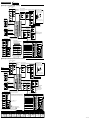
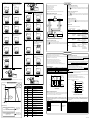
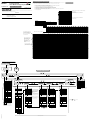
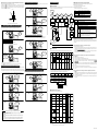
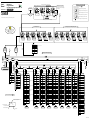
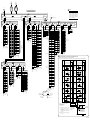
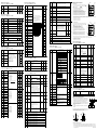
The following operating procedure describes an example of setting a K-type thermocouple (-200.0 to 500.0⬚C) and a measurement range of 0.0 to 200.0⬚C.
Setup Procedure
User’s
Manual
Model UP750
Program Controller
User’s Manual for Single-loop Control
Initial Settings
IM 05E01B02-02E
Denotes a step that must always be followed.
Power-on
1.
Denotes a step that should be followed as necessary.
PV
PVE2
TME
(Factory-set to unspecified. )
1
2
3
4
See 2. Setting PV Input Type (Setting First at Power-on),
or 3. Changing PV Input Type.
AL
1
PRG
RST
HLD
LOC
MAN1
MAN2
CAS
SET/ENT
Set the control
output.
MODE
2.
Be sure to follow this
step whenever a change of setting
is made to the PV input type.
Initialize
parameters.
input set
SETUP sub menu
RESET
SET/ENT
Press the
key once to display the parameter
IN1 (PV input type).
See 5. Initializing Parameters.
MENU:UPMD/IN
input 1 type select
NOTE
Set setup
parameters.
IN1
When initializing parameters is excuted, the controller initializes
the operating parameter and setup parameters. Therefore, check
that the appropriate value are set for the parameters after
initializing parameters. If changed to initial values, set them to the
appropriate values again.
MODE
PT.No
Set program
patterns.
MENU:UPMD/IN
input 1 range high
RH1
DISP
RUN
IN1
3. Event indicator
lamps
8. Instrument alarm
indicator lamp
4. Status indicator
lamps
PVE1
PVE2
1.
2.
3.
4.
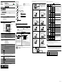
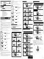
Name of Part
Indicator lamp for
PV2 display
Event indicator lamps
12.
and
Light-loader interface
6.
Process variable (PV)
display
Displays PV.
Displays an error code (in red) if an error occurs.
7.
Setpoint display (LCD)
Displays the name and value of a program setpoint (SP), output (OUT), deviation trend, or
a parameter.
Displays an error code if an error occurs.
8.
Instrument alarm
indicator lamp
9.
The AL1 lamp comes on in orange if instrument alarm 1 occurs.
SET/ENT key
4.
Press the
•
Used to switch or register a parameter. Pressing the key for more than 3 seconds allows you to switch
between the operating display and the main menu for operating parameter setting display alternately.
Example of Temperature Input
-270.0¡C
1370.0¡C
PT.No
2V
4V
5V
5.
0.0¡C
800.0¡C
Minimum value of
PV input range (RL1)
Set a range
to be
controlled
Maximum value of
PV input range (RH1)
Parameters to be set for temperature input
1. PV input type (IN1): Set according to a sensor
2. Maximum value of PV input range (RH1): Set the
maximum value of the range to be controlled.
3. Minimum value of PV input range (RL1): Set the
minimum value of the range to be controlled.
PV input range
RL1
UNI1
3
MODE
PT.No
6.
3
0.0m /h
50.0m /h
Minimum value of
PV input scale (SL1)
Maximum value of
PV input scale (SH1)
MODE
Presents a display for switching between the hold, advance, local, AUTO and MAN modes.
9.
type B
S
type S
R
type R
N
type N
E
type E
L(DIN)
type L
RESET
#3
DISP
RUN
type U2
RESET
SET/ENT
Press the
key once to display the parameter
“RL1” (minimum value of PV input range).
MENU:UPMD/IN
input 1 range low
RL1
MODE
RESET
W
type W
Platinel 2
Plati 2
PR20-40
PR2040
W97Re3W75Re25
W97Re3
#4
SETUP
-200.0
=
SET/ENT
DISP
PT.No
RUN
JPt1
RESET
RL1
RUN
RESET
11.
Press the
#3
MODE
PT.No
RUN
SET/ENT
RESET
MODE
DISP
PT.No
RUN
RESET
If the type of input is voltage, also configure the
PV Input Decimal Point Position (SDP1),
Maximum Value of PV Input Scale (SH1) and
Minimum Value of PV Input Scale (SL1)
parameters that follow this step.
How to return to a menu
12.
Press the
SET/ENT
key for more than 3 seconds. This returns you to the display shown at power-on (figure below).
PV2
RST lamp
ON.
PV
PVE1
PVE2
TME
1
2
3
4
AL
1
PRG
RST
HLD
LOC
MAN1
MAN2
CAS
MODE
PT.No
SP:
DISP
RUN
RESET
PTNO: 0
TM=-------
Standard
signal
0.0°C
SEGNO: 0/ 0
RCY: 0/ 0
DC voltage
#4
SETUP
0.0
=
0.4 to 2 V
1 to 5 V
0 to 2 V
0 to 10 V
0.0 to 1.2 V
(Note3)
-10 to 20 mV
0 to 100 mV
11. DISP key
12.
and
DISP
14. RUN key
15. RESET key
0.0 to 1.2 V
mV1
mV2
-10.00 to 20.00 mV
0.0 to 100.0 mV
NOTE
The controller may automatically initialize the registered operating parameter setpoints if any change is made to the
data item PV Input Type (IN1), Maximum Value of PV Input Range (RH1), Minimum Value of PV Input Range
(RL1), PV Input Decimal Point Position (SDP1), Maximum Value of PV Input Scale (SH1) or Minimum Value of
PV Input Scale (SL1). After a change has been made to any of these data items, be sure to verify the registered
operating parameter setpoints to ensure that they are correct. If any data item has been changed to its default, set it
to a required value.
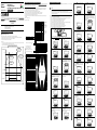
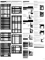
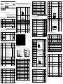
Ranges Selectable for PV Input
RTD
DC voltage(mV,V)
typeK1, K2, K3, J, T1, T2, B, S, R, N, E, L, U1, U2, W, Plati2, PR2040
JPt1, JPt2, Pt1, Pt2, Pt3, Pt4
0.4 to 2 V, 1 to 5 V, 0 to 2 V, 0 to 10 V, mV1, mV2
Used to change numerical values. On setting displays for various parameters, you can change target
setpoints, parameters, and output values (in manual operation). Pressing the
key decreases a
numerical value, while pressing the
key causes it to increase. You can hold down a key to gradually
increase the speed of change. These keys also switch between menu displays when a main menu or
submenu of parameter setting display is shown.
keys
13. PT.No key
0.4 to 2 V
1 to 5 V
0 to 2 V
0 to 10 V
Instrument
Measurement Accuracy
Input Range
Set the data item PV Input Type "IN1" to the OFF option to leave the PV input
type undefined.
-270.0 to 1370.0⬚C
-450.0 to 2500.0⬚F
-270.0 to 1000.0⬚C
-450.0 to 2300.0⬚F ⫾0.1% of instrument range ⫾1 digit at 0⬚C or more
-200.0 to 500.0⬚C
⫾0.2% ⫾1 digit for temperatures below 0⬚C,
-200.0 to 1000.0⬚F where the accuracy is: ⫾2% of instrument range ⫾1
-200.0 to 1200.0⬚C digit for temperatures below -200.0⬚C for a type-K
-300.0 to 2300.0⬚F thermocouple, or ⫾1% of instrument range ⫾1 digit for
temperatures below -200.0⬚C for a type-T thermocouple.
-270.0 to 400.0⬚C
-450.0 to 750.0⬚F
0.0 to 400.0⬚C
-200.0 to 750.0⬚F
0.0 to 1800.0⬚C ⫾0.15% of instrument range ⫾1 digit at 400⬚C or more
32 to 3300⬚F
⫾5% of instrument range ⫾1 digit at less than 400⬚C
0.0 to 1700.0⬚C
32 to 3100⬚F
⫾0.15% of instrument range ⫾1 digit
0.0 to 1700.0⬚C
32 to 3100⬚F
⫾0.1% of instrument range ⫾1 digit
-200.0 to 1300.0⬚C
⫾0.25% of instrument range ⫾1 digit for temperatures
-300.0 to 2400.0⬚F
below 0⬚C
-270.0 to 1000.0⬚C
-450.0 to 1800.0⬚F
-200.0 to 900.0⬚C
⫾0.1% of instrument range ⫾1 digit at 0⬚C or more
-300.0 to 1600.0⬚F ⫾0.2% ⫾1 digit for temperatures below 0⬚C, where the
accuracy is:⫾1.5% of instrument range ⫾1 digit for
-200.0 to 400.0⬚C
temperatures below -200.0⬚C for a type-E thermocouple.
-300.0 to 750.0⬚F
0.0 to 400.0⬚C
-200.0 to 1000.0⬚F
0.0 to 2300.0⬚C
⫾0.2% of instrument range ⫾1 digit
32 to 4200⬚F
0.0 to 1390.0⬚C
⫾0.1% of instrument range ⫾1 digit
32.0 to 2500.0⬚F
0.0 to 1900.0⬚C ⫾0.5% of instrument range ⫾1 digit at 800⬚C or more
No accuracy is guaranteed at less than 800⬚C
32 to 3400⬚F
0.0 to 2000.0⬚C
⫾0.2% of instrument range ⫾1 digit
32 to 3600⬚F
-200.0 to 500.0⬚C
⫾0.1% of instrument range ⫾1 digit (Note1) (Note2)
-300.0 to 1000.0⬚F
-150.00 to 150.00⬚C
⫾0.2% of instrument range ⫾1 digit (Note1)
-200.0 to 300.0⬚F
-200.0 to 850.0⬚C
-300.0 to 1560.0⬚F
⫾0.1% of instrument range ⫾1 digit (Note1) (Note2)
-200.0 to 500.0⬚C
-300.0 to 1000.0⬚F
-150.00 to 150.00⬚C
⫾0.2% of instrument range ⫾1 digit (Note1)
-200.0 to 300.0⬚F
0.400 to 2.000 V
1.000 to 5.000 V
0.000 to 2.000 V
⫾0.1% of instrument range ⫾1 digit
0.00 to 10.00 V
Display range is scalable in a range of -19999 to 30000.
Display span is 30000 or less.
0.000 to 1.200 V
*
Performance in the standard operating conditions (at 23⫾2⬚C, 55⫾10%RH, and 50/60 Hz power frequency)
Note1: The accuracy is ⫾0.3⬚C of instrument range ⫾1 digit for a temperature range from 0⬚C to 100⬚C.
Note2: The accuracy is ⫾0.5⬚C of instrument range ⫾1 digit for a temperature range from -100⬚C to 200⬚C.
Note3: Not used in single-loop control.
*
To receive a 4-20 mA DC signal, select a standard signal of 1 to 5 V DC and connect it to a 250⍀ resistor. This resistor is optional.
Model: X010-250-2 (resistor with M3.5 crimp-on terminal lugs)
Thermocouple
Used to switch between displays. Pressing this key while any operating display is shown
lets you switch to another prearranged operating display. Pressing this key while any
display other than an operating display is shown lets you go one display back.
(One to four presses (maximum) of this key lets you return to the current operating display,
though the number of presses depends on the operating status.)
Pt2
Pt3
Blinks during
change.
key once to register the setpoint.
RL1
Pt100
RESET
MENU:UPMD/IN
input 1 range low
DISP
RUN
SET/ENT
Pt1
RTD
DISP
PT.No
SETUP
500.0
=
MODE
JPt2
#4
changing!
0.0
=
SET/ENT
DISP
MENU:UPMD/IN
input 1 range high
SET/ENT
Press the
or
key to display the required
setpoint.
The figure below shows an example of setting the
minimum value of the PV input range to 0.0°C.
MENU:UPMD/IN
input 1 range low
SET/ENT
RH1
10.
#2
Press the
key once to display the parameter
“RH1” (maximum value of PV input range).
Parameters to be set for voltage input
1. PV input type (IN1): Set according to an input signal
2. Maximum value of PV input range (RH1): Set the maximum value of an input signal.
3. Minimum value of PV input range (RL1): Set the minimum value of an input signal.
4. Position of PV input decimal point (SDP1): Set the position of the decimal point for PV input display.
5. Maximum value of PV input scale (SH1): Set the maximum value of the scale to be controlled.
(Set a reading for the maximum value of the input signal.)
6. Minimum value of PV input scale (SL1): Set the minimum value of the scale to be controlled.
(Set a reading for the minimum value of the input signal.)
Press the DISP key once during parameter setting. This lets you return to the
parameter menu.
MODE
PT.No
SETUP
°C
=
RH1
PV input scale
B
type U1
#1
MENU:UPMD/IN
input 1 unit select
(input signal)
Set a range to
be controlled
Blinks during
change.
SETUP
200.0
=
RESET
SET/ENT
SET/ENT
PV input range
type T2
U(DIN)
SET/ENT
Press the
key once to display the parameter
“UNI1” (PV input unit).
Instrument
input range
Instrument
input range
RH1
DISP
RUN
type T1
T
key once to register the setpoint.
DISP
RUN
RUN
type J
JPt100
Example of Voltage Input
1V
MODE
SET/ENT
J
Thermocouple
SETUP
typeK3
=
SET/ENT
Press the
Blinks during
change.
SET/ENT
10. MODE key
type K2
type K3
DISP
MENU:UPMD/IN
input 1 range high
key once to register the setpoint.
IN1
8.
#1
MENU:UPMD/IN
input 1 type select
The controller displays an operating display when the power is turned on. The submenu “IN” appears at this
point if the type of PV input has not been defined yet. In this case, first press the
key once to display the
parameter “IN1” for the PV input type, and use the
key to display the input range code to use, then press
the
key to resister it. Then, set the maximum value (RH1) and minimum value (RL1) of the PV input
range (for voltage input, set the maximum value (SH1) and minimum value (SL1) of the PV input scale). See
the operating procedure below for more details.
The controller is configured to the default of each parameter at the factory before shipment.
First check these defaults listed in Parameters User’s Manual , and change their values if necessary.
SET/ENT
SET/ENT
15. RESET key
14. RUN key
5.
SET/ENT
•
keys
Is lit (in green) to indicate the status of operation or control.
PRG:Is lit when in program mode.
RST:Is lit when in reset mode.
HLD:Is lit when in hold mode.
LOC:Is lit when in local mode.
MAN1:Is lit when in manual mode.
MAN2:Not used in single-loop control.
CAS:Not used in single-loop control.
Interface for an adapter cable used when setting and storing parameters from a PC.
This requires an optional parameter setting tool.
Status indicator
lamps
PT.No
NOTE
11. DISP key
Function
Is lit when Loop2 PV is displayed in PV display.
Not used in single-loop control.
: Is lit (in green) when a program setpoint is increasing.
: Is lit (in green) when a program setpoint is constant.
: Is lit (in green) when a program setpoint is decreasing.
Show the statuses of PV events, time events and instrument alarms in orange.
PVE1 and PVE2 lamps: Come on when PV event 1 and PV event 2 turn on.
TME1 to TME4 lamps: Come on when time event 1 to time event 4 turn on.
AL1 lamp: Comes on when instrument alarm 1 turns on.
Program monitor lamps
2. Setting PV Input Type (Setting First at Power-on)
SET/ENT
5. Light-loader
interface
9. SET/ENT key
13. PT.No key
MODE
MODE
PT.No
changing!
typeK3
=
SET/ENT
2. Program monitor
lamps
type K1
#3
changing!
200.0
=
RESET
1. Names and Functions of Front Panel Parts
6. Process
variable (PV) display
7. Setpoint
display
10. MODE key
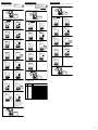
Instrument Input
Range Code
OFF
K
SET/ENT
MENU:UPMD/IN
input 1 type select
Controller operation
1. Indicator lamp for
PV2 display
Type
Unspecified
Press the
or
key to display the required
setpoint.
The figure below shows an example of setting the
maximum value of the PV input range to 200.0°C.
#1
Press the
or
key to display the required
setpoint.
The figure below shows an example of setting a Ktype thermocouple (-200.0°C to 500.0°C). See
“Instrument Input Range Codes.”
See Programming User’s Manual
7.
SETUP
OFF
=
SET/ENT
3.
1. Names and Functions of Front Panel Parts
2. Setting PV Input Type (Setting First at Power-on)
3. Changing PV Input Type
4. Setting Control Output Type
5. Initializing Parameters
RUN
Input
In steps 2 and later, illustrations of the LCD are cited to explain the procedure.
Set operating
parameters.
Contents
IN
DISP
(Factory-set to Time Proportional Relay Output. )
See 4. Setting Control Output Type.
This manual describes examples of setting PV input types, control output types. Carrying out settings described herein
allows you to perform basic control. Refer to examples of various settings to understand how to set parameters required.
Refer to Parameter Map User’s Manual for an easy to understand explanation of setting various parameters. If you
cannot remember how to carry out an operation during setting, press the DISP key no more than four times. This brings you
to the display (operating display) that appears at power-on. After carrying out the setting describes here, create programs in
Programming User’s Manual .
The PV display in the figure on the left
shows the error code for input burnout
(
) if PV input wiring is not yet
complete. The error code disappears
when you wire the PV input terminals
correctly.
Displays
submenu “IN”.
PVE1
PT.No
2nd Edition: Jul 1, 2001
Select the unit from the UNIT parameter.
Display view at power-on
PV2
Set PV input.
■ Instrument Input Range Codes
PT.No
Use this key when the controller is at a reset to select a program pattern number on
an operating display.
RUN
Pressing this key for more than 2 seconds while an operating display is shown starts the
controller.
RESET
Pressing this key for more than 2 seconds while an operating display is shown stops the
controller.
■ Setting of Main Parameters at the Factory before Shipment
Item
Control output
Control action
PID parameter
Factory-set defaults
for single-loop type/dual-loop type controllers
Time proportional PID relay output (variable)
Reverse action (variable)
P = 5.0%, I = 240 seconds, D = 60 seconds.
IM 05E01B02-02E (1)