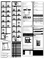
1
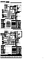
3. Lists of Program Parameters
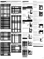
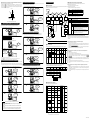
● Local Setpoint Parameters
Located in: Main menu =
Parameter
Symbol
LSP1
PID
E21A
E21B
E22A
E22B
E23A
E23B
E24A
E24B
E25A
E25B
E26A
E26B
E27A
E27B
E28A
E28B
PROG ; Submenu = LOC
Name of Parameter
* Parameters relating to PV or program setpoints should all be
set in real numbers. For example, use temperature values to
define program setpoints and PV event setpoints for
temperature input.
Setting Range and Description
Initial Value
User
Setting
Target Item
in CD-ROM
* The Target Item in CD-ROM column in the table below provided references from User s Manual (Reference) (CD-ROM version)
which describes items in more detail and items that are not contained in this manual.
● Program Parameters (Parameters for Setting the Final Target Setpoints and Segment
Times)
Setpoint for local-mode
operation
0.0 to 100.0% of PV input range
PID group number for
local-mode operation
1
Shown for segment PID parameters when the
setup parameter ZON is set to 0. This
parameter is factory-set so as not to appear.
1: Uses the 1st group of PID parameters.
2: Uses the 2nd group of PID parameters.
3: Uses the 3rd group of PID parameters.
4: Uses the 4th group of PID parameters.
5 to 8: Likewise, selecting these numbers uses
the 5th to 8th groups of PID parameters.
OFF, 1 to10, 28 to 31
OFF
1: PV high limit (energized, no stand-by action)
2: PV low limit (energized, no stand-by action)
3: Deviation high limit (energized, no stand-by action)
4: Deviation low limit (energized, no stand-by action)
5: Deviation high limit (de-energized, no stand-by action)
6: Deviation low limit (de-energized, no stand-by action)
7: Deviation high/low limits (energized, no stand-by action)
8: Deviation within high/low limits (energized, no stand-by
action)
9: PV high limit (de-energized, no stand-by action)
10: PV low limit (de-energized, no stand-by action)
See Parameter Map User’s Manual for details on other
alarm types.
Located in: Main menu =
PV/SP alarm: -100.0 to 100.0% of PV input
range
Deviation alarm: -100.0 to 100.0% of PV
input range span
Output value alarm: -5.0 to 105.0%
You can set a maximum of eight units each for the parameters listed below for each individual segment.
Local event-21 type
Local event-21
setpoint
Local event-22 type
Same as the E21A parameter.
Local event-22
setpoint
Same as the E21B parameter.
Local event-23 type
Same as the E21A parameter.
Local event-23
setpoint
Same as the E21B parameter.
Local event-24 type
Same as the E21A parameter.
Local event-24
setpoint
Same as the E21B parameter.
Local event-25 type
Same as the E21A parameter.
Local event-25
setpoint
Same as the E21B parameter.
Local event-26 type
Same as the E21A parameter.
Local event-26
setpoint
Same as the E21B parameter.
Local event-27 type
Same as the E21A parameter.
Local event-27
setpoint
Same as the E21B parameter.
Local event-28 type
Same as the E21A parameter.
Local event-28
setpoint
Same as the E21B parameter.
0.0% of PV input range
Parameter
Symbol
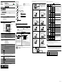
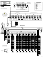
PROG ; Submenu = PRG
Name of Parameter
TSP1
TIME
The final target setpoint of each segment.
Time-set segment time
TM.RT
Ramp-set segment time
Time setpoint: - (unregistered)
0.00 to 99.59 (“hour, minute” or “minute, second”)
Without a time setpoint, it is not possible to create programs.
For ramp segments (ramp setpoint): - (unregistered), 0.0 to 100.0% of PV input
range span per hour or minute
For soak segments (time setpoint): 0.00 to 99.59 (“hour, minute” or “minute, second”)
Without a time setpoint or a ramp grade setpoint, it is not possible to create programs.
PID
Segment PID group
number
PTN
Pattern number
SEG
Segment number
SSP1
STC
Starting target setpoint
Start code
PV/SP high limit alarm:
100.0% of PV input range.
Deviation alarm:
0.0% of PV input range span.
Other PV/SP low limit alarms:
0.0% of PV input range.
Output high limit alarm: 100.0%
Output low limit alarm: 0.0%
Located in: Main menu =
Parameter
Symbol
Ref.5.2(9)
EVn
ONn
OFFn
TYn
Setting Range and Description
1: Program pattern 1
2: Program pattern 2
3: Program pattern 3
4 to 300: Likewise, specifying these numbers sets their
corresponding program pattern numbers.
0: Shows parameters for setting the starting target setpoint,
start code, etc.
1 to 99: Specify the corresponding segment numbers.
Specify 0 when creating a program for the first time.
0.0 to 100.0% of PV input range
PEn
Event number
Initial Value
0: Unregistered.
1: Time event 1 (terminal numbers 34 - 35 )
2: Time event 2 (terminal numbers 33 - 35 )
3: Time event 3 (terminal numbers 32 - 35 )
4: Time event 4 (terminal numbers 31 - 35 )
5 to 16: Time events 5 to 16 (see the CD-ROM version user s manual for details on the terminal number)
21: PV event 1 (terminal numbers 6 - 7 )
22: PV event 2 (terminal numbers 5 - 7 )
23 to 28: PV events 3 to 8 (see the CD-ROM
version user s manual for details on the terminal
number)
User
Setting
Target Item
in CD-ROM
Setpoint of SEG.T (Segment Setting Method) Setup Parameter
0 (factory-set default)
1
Time setting (method 1)
Ramp setting (method 2)
Ref.5.1(1)
1. Creating programs by setting final target setpoint and
segment time
As shown in the figure on the right, this method creates programs by
setting a segment time and a final target setpoint on a segment-bysegment basis.
Junction code
OFF: No function
0.0 to 10.0% of PV input range span
OFF: No function
0.01 to 99.59 ( hour, minute or minute, second )
Use the TMU setup parameter to set the time unit.
2.WZ1
2.WTM
3.WZ1
3.WTM
4.WZ1
4.WTM
5.WZ1
5.WTM
RCY
2nd group of wait
zones
Same as the 1st group of wait zones.
2nd group of wait
times
Same as the 1st group of wait times.
3rd group of wait
zones
Same as the 1st group of wait zones.
3rd group of wait
times
Same as the 1st group of wait times.
4th group of wait
zones
Same as the 1st group of wait zones.
4th group of wait
times
Same as the 1st group of wait times.
5th group of wait
zones
Same as the 1st group of wait zones.
5th group of wait
times
Same as the 1st group of wait times.
Number of repetitions
0 to 999: The controller repeats the segment specified by the RST
and REN parameters as many times as defined by this parameter.
CONT: The controller indefinitely repeats the segment specified
by the RST and REN parameters.
0
1ⱕRSTⱕRENⱕ99
1
User
Setting
Target Item
in CD-ROM
Setting Range and Description
Final target setpoint set for
segment immediately preceding
or the starting target setpoint
if this is the point of starting
program operation
Define the ramp grade as the
amount of change in the
setpoint per hour or per minute.
Ramp
grade
Controller Settings
Setpoint of TMU (Program Time Unit) Setup Parameter
hh:mm (factory-set default)
mm:ss
Note: The “Program Time Unit (TMU)” parameter is the time unit you use when creating programs.
Setpoint
Final target
setpoint
Final target setpoint set for
segment immediately preceding
or the starting target setpoint
if this is the point of starting
program operation
Segment time
Define as
hour and minute or
minute and second.
● Program Parameters (Parameters for Editing Programs)
OFF
Located in: Main menu =
Symbol on PV display
Ref.5.2(3)
Ref.5.2(4)
Ref.5.3(6)
Final target
setpoint
Number of remaining
unused segments.
Setting Range and Description
Initial Value
User
Setting
Target Item
in CD-ROM
Read-only
Ref.5.3(1)
(ALL.S)
Ref.5.2(4)
Maximum value of
PV input range (RH1)
Program setpoint
3 3rd group of
PID constants
Reference point 2
(2.RP1)
2 2nd group of
PID constants
Reference point 1
(1.RP1)
PV input value
[1] The controller uses the 1st group of PID constants if the
PID constants
PV input value is within the zone set off by the minimum
Minimum value of
value of the PV input range and reference point 1.
PV input range (RL1)
Segment 1
Segment 2
Segment 3
[2] The controller uses the 2nd group of PID constants if the
PV input value is within the zone set off by reference point 1 and reference point 2.
[3] The controller uses the 3rd group of PID constants if the PV input value is within the zone set off by reference point 2 and the
maximum value of the PV input range.
PID constants can be selected according to the deviation
in two ways. One method is to select a group of PID
constants only by a deviation from a program setpoint.
The other method is to use a reference point, as discussed
earlier, as well as a deviation from a program setpoint,
to switch between groups of PID constants.
[1] The controller uses the 1st group of PID constants.
[2] The controller uses the PID constants of the group
number set in PID group number (GRP).
Ramp upgrade of
5¡C per minute
PV input value
Maximum value of
PV input range (RH1)
[2]
Method 2:
As shown in the figure on the right, the controller selects
an appropriate group of PID constants for each zone and,
if the PV input value goes beyond the given deviation
from the program setpoint, selects the PID constants of
the group number set in PID group number (GRP).
Time
Setpoint
1. Letting the controller run from a starting target setpoint
Number of segments
within a pattern.
Ref.5.3(2)
Number of remaining
unused events.
Ref.5.3(3)
[2]
Reference
deviation (RDV1)
Reference
deviation (RDV1)
[1]
[1]
Program setpoint
[1]
[2]
Minimum value of
PV input range (RL1)
Segment 1
Segment 2
PV input value
Maximum value of
PV input range (RH1)
[3]
[3]
Reference
deviation (RDV1)
Reference
deviation (RDV1)
[2]
Segment 1
A starting target setpoint refers to a setpoint from which program
operation begins. The controller operates in such a manner that the
setpoint changes to the final target setpoint over the segment time
set for segment 1, irrespective of what the PV value is.
Segment 2
Final target setpoint
[2]
Reference point 1
(1.RP1)
[1]
Program setpoint
[1]
[3]
Minimum value of
PV input range (RL1)
Segment 1
Segment 2
[1] The controller uses the 1st group of PID constants
if the PV input value is both within the zone set off
by the minimum value of the PV input range and reference point 1 and within the given reference deviation bandwidth.
[2] The controller uses the 2nd group of PID constants if the PV input value is both within the zone set off by reference points 1 and the
maximum value of the PV input range, and within the given reference deviation bandwidth.
[3] The controller uses the PID constants of the group number set in PID group number (GRP).
Starting target setpoint
Controller Settings
Program
setpoint
Set the STC (Start Code) program parameter to 0 .
Time
Segment time
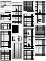
2. Letting the controller start from the current setpoint and
Starting Point Controller Behavior
of Operation
a
Begins to run from point a
the time setting defined for
b
Begins to run from point b
the time setting defined for
c
Begins to run from point c
the time setting defined for
d
Begins to run from point d
the time setting defined for
e
Begins to run from point e
the time setting defined for
Start of program operation
Setpoint
a
according to
segment 1.
according to
segment 1.
according to
segment 1.
according to
segment 1.
according to
segment 1.
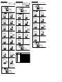
■ Retaining the End-of-Program State (Holdmode End)
End of program
Setpoint
This function keeps the controller in the same state as when program operation was
completed. When in hold operation, the controller retains its states of control output and event output. To cancel hold operation, use either key operation or external
contact input. When the hold operation is cancelled, the control output is set to 0%
or OFF, and the event output is set to OFF.
To retain the end-of-program state, set the Junction Code program parameter of the
segment in question to “1”.
run according to time settings defined for segment 1
This method is not available if the SEG.T (Segment Setting Method)
parameter is set to “ramp setting.”
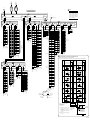
PROG ; Submenu = EDIT
Name of Parameter
As shown in the figure on the right, three zones are set for the
controller to automatically switch from one group of PID constants to another. Two zones can also be set for the controller to
switch between two groups of PID constants.
Method 1:
As shown in the figure on the right, the controller selects
the PID constants of the group number set in PID group
number (GRP) if the PV input value goes beyond the
given deviation from the program setpoint.
You can determine how the controller should behave at the start of program operation.
Target Item
in CD-ROM
Segment 2
Segment 1
50¡C
The junction code (JC) basically used to specify the condition
0
for moving from one segment to the next and the intra-segment
operating condition.
0: Switching for continuation
1: Hold-on switching (the controller holds the end-of-segment
setpoint when the segment is completed, to perform control).
2: Local-mode end (the controller switches to a local setpoint
when the segment is completed).
11 to 15: Wait during switching between segments (see the
CD-ROM version user’s manual).
21 to 25: Wait within a segment interval (see the CD-ROM
version user’s manual).
INSERT: Allows a segment to be added to the end of a specified
segment.
DELETE: Allows a specified segment to be deleted.
101 to 199:Linked to the pattern 1 to 99.
For example, when setting “102” in JC of the final segment,
the operation for pattern 2 is started after the end of pattern 1.
< Notes at pattern-link >
- Parameter STC is available.
- PV event and time event are reset.
- Parameter SST is not available.
OFF
Minimum value of
PV input range (RL1)
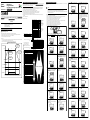
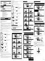
● Selecting PID Constants According to the Deviation
To change the temperature linearly over a minute, set the TMU parameter to “mm:ss” Setpoint
(minute and second) before you begin programming. When programming the con100¡C
troller, set the Segment Time (TM.RT) parameter for segment 1 to 5°C. This allows
the controller to raise the setpoint in increments of 5°C per minute during the interval of segment 1.
User
Setting
1st group of
PID constants
PV input value
Controller Settings
• Splitting the control range into two zones
- To split the control range into two zones, define reference point 1 (i.e., the 1.RP1 setup parameter).
- Define the 1st and 2nd groups of PID constants (i.e., the 1.P, 1.I and 1.D operating parameters for the 1st group and the 2.P, 2.I and 2.D
operating parameters for the 2nd group).
• Splitting the control range into three zones
- To split the control range into three zones, define reference points 1 and 2 (i.e., the 1.RP1 and 2.RP1 setup parameters).
- Define the 1st, 2nd and 3rd groups of PID constants (i.e., the 1.P, 1.I and 1.D operating parameters for the 1st group, the 2.P, 2.I and 2.D
operating parameters for the 2nd group and the 3.P, 3.I and 3.D operating parameters for the 3rd group).
■ Controller Behavior at the Start of Program Operation
Initial Value
Controller Settings
- Configure the 1st group of PID constants
(1.P, 1.I and 1.D operating parameters).
1 1st group of
Ref.3.4(5)
PROG ; Submenu = PRG
Name of Parameter
Ref.5.2.(1)
Initial Value
Time
Time
● Program Parameters (Junction Code Parameter)
JC
Setting Range and Description
Segment time
Final target
setpoint
When creating a soak segment during programming, set a time
(“hour and minute” or “minute and second”) rather than a ramp
grade.
For example, configure segment 1 so the temperature rises in increments of 5°C per minute from 50°C to 100°C, as shown in the
figure on the right.
PV/SP high-limit alarm: 100.0% of
PV input range.
Deviation alarm: 0.0% of PV input
range span.
Other PV/SP low limit alarms: 0.0%
of PV input range.
Output high limit alarm: 100.0%
Output low limit alarm: 0.0%
Program setpoint
Maximum value of
PV input range (RH1)
Setpoint
When changing the setpoint linearly over an hour
When changing the setpoint linearly over a minute
Ref.3.4(6)
As shown in the figure on the right, the controller uses one
group of PID constants over the range from the minimum value
to the maximum value of the PV input range.
● Selection of PID Constants when
the Control Range Is Split into Three
Zones
Time
OFF
OFF, 1 to 10, 28 to 31
1: PV high limit (energized, no stand-by action)
2: PV low limit (energized, no stand-by action)
3: Deviation high limit (energized, no stand-by action)
4: Deviation low limit (energized, no stand-by action)
5: Deviation high limit (de-energized, no stand-by
action)
6: Deviation low limit (de-energized, no stand-by
action)
7: Deviation high/low limits (energized, no stand-by
action)
8: Deviation within high/low limits (energized, no
stand-by action)
9: PV high limit (de-energized, no stand-by action)
10: PV low limit (de-energized, no stand-by action)
See ■ List of PV Event Types and Instrument Alarm
Types in Parameter Map User’s Manual for details
on other alarm types.
PV/SP alarm: -100.0 to 100.0% of PV input
range
Deviation alarm: -100.0 to 100.0% of PV
input range span
Output value alarm: -5.0 to 105.0%
Target Item
in CD-ROM
Ref.3.4(6)
PV event type
PV event setpoint
User
Setting
target setpoint and ramp
As shown in the figure on the right, this method
creates programs by setting a final target setpoint
and a ramp grade on a segment-by-segment basis. Define the ramp grade as the amount of
change in the setpoint per hour or per minute.
Ref.3.4(5)
OFF: Unused.
OFF
0.00 to 99.59 ( hour, minute or minute, second )
0.0% of PV
input range
-1: Shows parameters for setting the wait and repeat actions. 0
0: Program operation begins with the starting target setpoint .
1: Ramp-prioritized PV start (program operation begins with
the PV value by giving priority to the ramp of segment 1)
2: Time-prioritized PV start (program operation begins with
the PV value by giving priority to the time of segment 1)
TIP: The option -1 is not a setpoint.
2. Creating programs by setting final
● When One Group of PID Constants
Is Used (factory-set default)
Final target
setpoint
Final target setpoint set for
segment immediately preceding
or the starting target setpoint
if this is the point of starting
program operation
Ref.5.1(2)
The UP750 offers two methods of PID switching. One of the methods is to automatically switch between groups of PID constants according
to the temperature zone. The other method is to automatically switch between groups of PID constants on a segment-by-segment basis. This
paragraph explains the method of switching between groups of PID constants according to the temperature zone. You can set a maximum of
seven temperature zones. When shipped from the factory, the UP750 is configured so that it operates in zone 1 only and uses only one group
of PID constants.
This single definite line is
referred to as a segment.
Setpoint
Segment 1
Parameter
Symbol
0
1st group of wait
zones
1st group of wait
times
Start-of-repetition
segment number
End-of-repetition
segment number
Controller Settings
Choose the desired method and unit from the two programming methods and time unit options discussed above. Then, create
programs according to the chosen options.
0
Off time of time event
PROG ; Submenu = PRG
Name of Parameter
Target Item
in CD-ROM
You can create programs using either method 1 or 2 described below. The controller is factory-set to “method 1”. To create programs using
method 2, change the setpoint of the SEG.T (Segment Setting Method) setup parameter to “1”.
Before you begin programming, determine whether your programs are created using the time unit of “hour and minute” or “minute and
second.” The controller is factory-set to the “hour and minute” time unit. To create programs using the “minute and second” time unit, change
the setpoint of the TMU (Program Time Unit) setup parameter to “mm:ss”.
1
Initial Value
OFF: Unused.
OFF
0.00 to 99.59 ( hour, minute or minute, second )
Located in: Main menu =
1.WZ1
1.WTM
RST
REN
Setting Range and Description
On time of time event
The parameters listed below are shown when the Start Code (STC) parameter is set to “-1”.
Parameter
Symbol
User
Setting
PROG ; Submenu = PRG
Name of Parameter
● Program Parameters (Parameters for Setting the Wait and Repeat Actions)
Located in: Main menu =
This parameter is shown for segment PID parameters when
the setup parameter “ZON” is set to 0.
This parameter is factory-set so as not to appear.
1 to 8
PROG ; Submenu = PRG
Name of Parameter
Initial Value
Final target setpoint
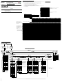
Use the program pattern setup chart discussed in “1. Program Pattern Setup Charts” of this manual, to record your setpoints of program
parameters.
Located in: Main menu =
Setting Range and Description
■ PID Switching (Zone PID)
■ Programming
● Program Parameters (Parameters for Setting the Event Action)
● Program Parameters (Parameters for Setting the Conditions of Program Operation
Startup)
Parameter
Symbol
4. Explanation of Program Functions
* The User Setting column in the table below is provided for the customer to record setpoints.
Final target setpoint
Time
b
Program
setpoint
c
d
■ Suspending the Progress of a Program (Wait Function)
e
Segment
Start of 1
program operation
Segment Segment Segment
2
3
4
Segment
5
Time
Controller Settings
When a running program moves from one segment to another, the wait function places the program in a wait (stand-by) state, by using a wait
zone and a wait time, until any deviation is cancelled. A wait zone is a deviation bandwidth from which the degree of PV input tracking is
judged. A wait time is the length of time that elapses until the PV input enters the wait zone. The program progresses if the PV input fails to
re-enter the wait zone within the wait time.
When the program is in wait state, the time setpoints of Segment Time and Time Event parameters temporarily cease to be passed. At this
point, the output based on the Time Event parameter is retained.
See User’s Manual (Reference) (CD-ROM version) for more information.
Set the STC (Start Code) program parameter to 2 .
(PTN.S)
3. Letting the controller start from the current setpoint and run according to ramp settings defined for segment 1 of the created program
(ALL.E)
Program pattern copying
(COPY)
Program pattern clearance
(CLEAR)
1
Ref.5.2(6)
Specify the numbers of the source-of-copying
program pattern and target-of-copying program
pattern. (1 to 300)
Specify the number of the program pattern to be
cleared.
(1 to 300)
Ref.5.3(4)
Ref.5.3(5)
Starting Point Controller Behavior
of Operation
Begins to run from point C1 (ignores the
a
time setting defined for segment 1).
b
Begins to run from point C1 (ignores the
time setting defined for segment 1).
c
Begins to run from point C1 (ignores the
time setting defined for segment 1).
d
Begins to run from point D1 according to
the preset ramp setting (the time setting
defined for segment 1 is reduced).
e
Begins to run from point E1 according to
the preset ramp setting.
Setpoint
a
A1
B1
b
e
Program
setpoint
C1
c
d
D1
E1
Segment
Start of 1
program operation
Segment Segment Segment
2
3
4
Segment
5
Time
Controller Settings
Set the STC (Start Code) program parameter to 1 .
IM 05E01B02-04E (2)