1
2. Example of Program Pattern Setup Charts
User’s
Manual
Model UP750
Program Controller
User’s Manual for Single-loop Control
Programming
IM 05E01B02-03E
2nd Edition: Jul 1, 2001
This manual explains how to create programs by citing specific examples. Create user programs by referring to the given
programming examples. Use the parameter map included in “2. Program Parameter Map,” in Program Parameters
User’s Manual , in order to further familiarize yourself with the required operations.
Be sure to carry out the settings instructed in Initial Settings User’s Manual before beginning any of the tasks discussed
in this manual.
3. Creating Program Patterns
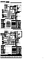
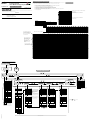
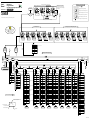
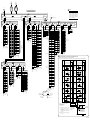
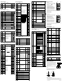
Complete the following setup chart before setting programs in the controller. Filling in the chart makes it easier for you to input
program data into the controller. See “1. Program Pattern Setup Charts”, in Program Parameters User’s Manual .
In the following chart, fill in the fields with bold-face borders.
1.
2.
3.
4.
5.
6.
7.
8.
Maximum value of PV input range: Setpoint of the “Maximum Value of PV Input Range (RH1)” setup parameter
Minimum value of PV input range: Setpoint of the “Minimum Value of PV Input Range (RL1)” setup parameter
PV input unit: Setpoint of the “PV Input Unit (UNI1)” setup parameter
Program time unit: Setpoint of the “Program Time Unit (TMU)” setup parameter
Segment setting method: Setpoint of the “Segment Setting Method (SEG.T)” setup parameter
Starting target setpoint: Setpoint of the “Starting Target Setpoint (SSP1)” program parameter
Start code: Setpoint of the “Start Code (STC)” program parameter
Final target setpoint, Segment time, Events (PV event and Time event) and Junction code: setpoint of each program
parameter
9. Draw the program pattern.
Example of Chart Entries
6 25°C
Starting target setpoint 1 (SSP1)
Starting target setpoint 2 (SSP2)
Contents
7
Start code (STC)
1st group of wait zones (1.WZ1)
1. Overview of Program Patterns
2. Example of Program Pattern Setup Charts
3. Creating Program Patterns
4. Changing Program Patterns
1st group of wait times (1.WTM)
2nd group of wait zones (2.WZ1)
2nd group of wait times (2.WTM)
0
Define this parameter
when using the
controller as a
program pattern
generator. See User’s
Manual (Reference)
(CD-ROM version) for
more information.
TIME
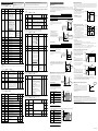
Before creating the program, reverify the Maximum Value of PV Input Range (RH1), Minimum Value of PV Input
Range (RL1), Program Time Unit (TMU), and Segment Setting Method (SEG.T) parameters.
If the setting of the setup parameter “SEG.T” is changed, the program patterns created and stored so far will be all
cleared (initialized) !! Be careful.
4 Hour, minute
RST lamp
ON.
PV
TME
1
2
3
4
Unit 3 °C
Maximum value of PV input range (RH1)
100%
1
MODE
RUN
Temperature
2
80°C
1
3.
25°C
2
Press the
“LOC”.
Final target setpoint 1 (TSP1)
MODE
RUN
SET/ENT
SET/ENT
key once to register the setpoint.
MENU:PROG/PRG
start set point 1
SSP1 =
SET/ENT
SET/ENT
#3
19.
PV event type (TY1)/on time of time event (ON1)
PV event setpoint (PE1)/off time of time event (OFF1)
4.
21
1
7
0 min
Press the
“PRG”.
MODE
80 min.
10 min.
RUN
RUN
MODE
RESET
PT.No
29.
DISP
RUN
RESET
SET/ENT
Press the
key once to display the Segment Time
parameter “TIME” for segment 2.
#29
MENU:PROG/PRG
segment time
changing!
21
=
MODE
TIME
SET/ENT
DISP
RUN
10.
MENU:PROG/PRG
start code select
STC
SET/ENT
=
=
SET/ENT
-
MODE
PT.No
Press the
or
#29
DISP
RUN
RESET
key to display the required setpoint.
MENU:PROG/PRG
segment time
21
MODE
MODE
PT.No
#5
20.
0
PT.No
11.
=
RESET
30.
#26
TIME
#26
changing!
1h20
=
SET/ENT
RESET
key once to display the submenu
SET/ENT
DISP
RUN
SET/ENT
MENU:PROG/PRG
PV event 1 type
RUN
PT.No
Press the
key once to display the PV Event Type
parameter “TY1”.
DISP
MODE
RESET
31.
Press the
SET/ENT
#30
DISP
RUN
RESET
key once to register the setpoint.
MENU:PROG/PRG
segment time
#26
RESET
=
OFF
TIME
=
1h20
SET/ENT
Press the
key once to display the Target
Setpoint parameter “TSP1” for segment 1. At this
point, the PV display shows “001.01” (the first three
digits denote the pattern number and the last two
digits the segment number).
MENU:PROG/PRG
target set point 1
PRG
programming
sub menu
SET/ENT
TSP1
=
MODE
PT.No
21.
Press the
or
SET/ENT
DISP
RUN
#24
PT.No
key to display the required setpoint.
MENU:PROG/PRG
PV event 1 type
25.0°C
TY1
32.
DISP
RUN
RESET
SET/ENT
Press the
key once to display the Event Number
parameter “EV1”.
MENU:PROG/PRG
event 1 no. select
#30
changing!
7
=
MODE
RESET
The figure below shows an example of setting the
parameter to “Deviation high and low limits Alarm”
(setpoint 7).
PV event type (TY3)/on time of time event (ON3)
EV1
#29
=
0
PV event setpoint (PE3)/off time of time event (OFF3)
SET/ENT
MODE
PT.No
Not used in this example.
Outputs an alarm if the temperature goes beyond the range “program setpoint ⫾5°C.”
8
PV event type (TY4)/on time of time event (ON4)
PV event setpoint (PE4)/off time of time event (OFF4)
Event number (EV5)
PV event type (TY5)/on time of time event (ON5)
ON
OFF
PV event setpoint (PE5)/off time of time event (OFF5)
Event number (EV6)
Time event 1
PV event type (TY6)/on time of time event (ON6)
RUN
MODE
RESET
PT.No
DISP
RUN
Not used in this example.
5.
SET/ENT
Press the
key once to display the Pattern
Number parameter “PTN”. At this point, the PV
display shows “001.00” (the first three digits denote
the pattern number and the last two digits the
segment number).
12.
Press the
setpoint.
or
key to display the required
22.
Press the
PT.No
33.
PTN
=
MENU:PROG/PRG
target set point 1
TSP1
1
Press the
or
SET/ENT
MODE
PV event type (TY8)/on time of time event (ON8)
PT.No
PV event setpoint (PE8)/off time of time event (OFF8)
0
6.
SET/ENT
DISP
RUN
SET/ENT
MENU:PROG/PRG
SEGno. input
SEG
SET/ENT
=
13.
Press the
#30
MODE
SET/ENT
DISP
RUN
RESET
PT.No
Press the
key once to display the Starting
Target Setpoint parameter “SSP1”.
MENU:PROG/PRG
start set point 1
14.
=
=
RESET
Press the
or
MODE
PT.No
8.
Press the
setpoint.
or
SET/ENT
DISP
RUN
PT.No
key to display the required
The figure below shows an example of setting the
parameter to “25.0°C”.
15.
Press the
setpoint.
or
#3
changing!
25.0°C
SSP1 =
MODE
PT.No
#26
PE1
RUN
RESET
#29
=
1
RUN
SET/ENT
MODE
RESET
PT.No
35.
DISP
RUN
RESET
SET/ENT
Press the
key once to display the On Time of Time
Event parameter “ON1”.
MENU:PROG/PRG
time event 1 ON time
#31
=
ON1
=
#30
OFF
MODE
SET/ENT
DISP
RUN
RUN
RESET
MENU:PROG/PRG
segment time
25.
Press the
SET/ENT
PT.No
PT.No
DISP
RUN
RESET
key once to register the setpoint.
36.
or
MENU:PROG/PRG
PV event 1 set point
=
#31
RESET
key to display the required setpoint.
MENU:PROG/PRG
time event 1 ON time
5.0°C
ON1
#26
DISP
RUN
Press the
The figure below shows an example of setting the
parameter to “0 min (setpoint 0h00)”.
changing!
0h20
=
MODE
MODE
RESET
DISP
The figure below shows an example of setting the
parameter to “20 min (0h20)”.
SET/ENT
DISP
EV1
changing!
5.0°C
SET/ENT
MODE
PT.No
SET/ENT
MENU:PROG/PRG
event 1 no. select
key to display the required
TIME
RESET
key once to register the setpoint.
DISP
MENU:PROG/PRG
PV event 1 set point
PE1
MENU:PROG/PRG
start set point 1
SET/ENT
RUN
-
MODE
RESET
Press the
DISP
The figure below shows an example of setting the
parameter to “5.0°C”.
PT.No
MODE
34.
#31
key to display the required setpoint.
SET/ENT
SET/ENT
PT.No
0.0°C
PT.No
24.
MENU:PROG/PRG
segment time
TIME
MODE
RESET
SET/ENT
SET/ENT
Press the
key once to display the Segment
Time parameter “TIME” for segment 1.
0.0°C
RUN
#24
DISP
RUN
=
SET/ENT
DISP
MENU:PROG/PRG
PV event 1 set point
SET/ENT
#3
MODE
80.0°C
MODE
#29
changing!
1
RESET
MENU:PROG/PRG
target set point 1
=
key to display the required setpoint.
EV1
Press the
key once to display the PV Event
Setpoint parameter “PE1”.
key once to register the setpoint.
TSP1
SET/ENT
SSP1 =
SET/ENT
23.
DISP
RUN
RESET
MENU:PROG/PRG
event 1 no. select
7
PT.No
PE1
#2
0
PT.No
7.
PT.No
Press the
key once to display the Segment
Number parameter “SEG”.
(Note) This parameter is shown for segment PID parameters when the setup paramater “ZON” is set to 0.
MODE
RESET
=
SET/ENT
PV event setpoint (PE7)/off time of time event (OFF7)
Event number (EV8)
RUN
#24
changing!
80.0°C
=
DISP
The figure below shows an example of setting the
parameter to “time event 1 (setpoint 1)”.
The figure below shows an example of setting the
parameter to “80.0°C”.
#1
MODE
RESET
key once to register the setpoint.
TY1
PV event type (TY7)/on time of time event (ON7)
0
SET/ENT
RUN
MENU:PROG/PRG
PV event 1 type
MENU:PROG/PRG
PTno.input
0
SET/ENT
DISP
PV display
Event number (EV7)
Junction code (JC)
MODE
RESET
PT.No
PV event setpoint (PE6)/off time of time event (OFF6)
The output turns on after 20 minutes have elapsed since the start of program operation.
Then, it turns off after 100 minutes have elapsed from the start of program operation.
SET/ENT
DISP
SET/ENT
Event number (EV4)
PV event 1
80.0°C
RESET
PV display
Event number (EV3)
Start of program operation
RUN
MENU:PROG/PRG
event 1 no. select
DISP
5°C 80 min
PV event setpoint (PE2)/off time of time event (OFF2)
Time
SET/ENT
DISP
=
#24
The figure below shows an example of setting the
parameter to “1 hr and 20 min (setpoint 1h20)”.
PV event type (TY2)/on time of time event (ON2)
0°C
MODE
key once to register the setpoint.
Press the
key once to display the Start Code
parameter “STC”.
DISP
Event number (EV2)
25°C
20 min.
SET/ENT
TY1
20 min 80 min 10 min
PID number (PID) (Note)
Starting target
setpoint (SSP1)
Segment time for segment 3
Press the
1 2 3 4 5 6 7 8 9 10 11 12 1
MODE
RESET
MENU:PROG/PRG
target set point 1
25.0°C
PT.No
local mode set
sub menu
SET/ENT
RUN
SET/ENT
TSP1
key to display the required setpoint.
EV1
RESET
key once to display the submenu
80°C 80°C 0°C
DISP
Press the
key once to display the Target Setpoint
parameter “TSP1” for segment 2. The setpoint of this
parameter is not changed in this example. At this point,
the PV display shows “001.02” (the first three digits
denote the pattern number and the last two digits the
segment number).
0
MENU:PROG/PRG
event 1 no. select
Final target setpoint 2 (TSP2)
Event number (EV1)
Segment time for segment 2
or
SEGNO: 0/ 0
RCY: 0/ 0
DISP
PT.No
3
28.
#29
=
PT.No
LOC
0
Segment time (TIME/TM.RT)
Segment time for segment 1
Press the
EV1
Segment No.
Target setpoint
(TSP1) to be reached
by segment 3
Target setpoint
(TSP1) to be reached
by segment 1
Press the
9.
programming
main menu
PT.No
Minimum value of PV input range (RL1)
0%
PT.No
80°C
Define when using the controller
as a program pattern generator.
See User’s Manual (Reference)
(CD-ROM version) for more information.
Target setpoint
(TSP1) to be reached
by segment 2
EV1
0.0°C
PTNO: 0
TM=-------
RESET
PROG
SET/ENT
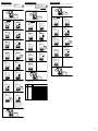
Example of Creating Program Pattern 1
MENU:PROG/PRG
event 1 no. select
18.
SP:
DISP
SET/ENT
100
MODE
RESET
The figure below shows an example of the parameter
set to “PV event 1” (setpoint 21).
Press the
key for more than 3 seconds to call
up the main menu “PROG”.
9
0
PV display
PRG
RST
HLD
LOC
MAN1
MAN2
CAS
SET/ENT
2.
RUN
#53
=
SET/ENT
DISP
SET/ENT
In steps 2 and later, illustrations of the LCD are cited to explain the procedure.
Start-of-repetition segment number (RST)
MENU:PROG/PRG
junction code select
JC
Press the
key once to display the Event
Number parameter “EV1”.
PT.No
Displays a
process variable
(PV) value.
PVE1
1
End-of-repetition segment number (REN)
Event output
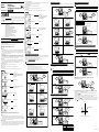
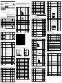
• Set a deviation of 5°C on both the positive and negative sides of a program setpoint to allow the controller to output an
event signal if the temperature goes beyond the deviation range.
• Let the controller output an event signal when the temperature stabilizes to 80°C.
17.
SET/ENT
Press the
key once to display the Junction Code
parameter “JC” for segment 1.
The setpoint of this parameter is not changed in this
example.
#26
PVE2
AL
Number of repetitions (RCY)
Segment setting method (SEG.T) 5 Time setting
27.
0h20
MODE
Bring the operating display into view (appears at power-on).
5th group of wait times (5.WTM)
Program time unit (TMU)
=
PT.No
SET/ENT
1.
PT.No
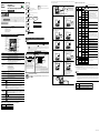
The programming example given here demonstrates how to do the tasks outlined below.
1. Program the controller to start program operation at 25°C and raise the temperature up to 80°C in 20 minutes.
2. When the temperature reaches 80°C, keep it at this level for 80 minutes.
3. Finally, lower the temperature to 0°C in 10 minutes.
SET/ENT
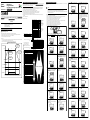
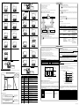
The programming example given in this manual includes the following steps.
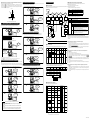
• Step 5 selects the program pattern number (PTN).
• Steps 7 to 9 configure the parameter Starting Target Setpoint (SSP1) (so that the program starts from 25°C).
• Steps 11 to 13 configure the Final Target Setpoint (TSP1) parameter for segment 1.
• Steps 14 to 16 configure the Segment Time (TIME) parameter for segment 1.
• Steps 17 to 25 configure the PV Event parameters (EV1, TY1 and PE1).
• Step 28 configures the Final Target Setpoint (TSP1) parameter for segment 2 (not changed in this example).
• Steps 29 to 31 configure the Segment Time (TIME) parameter for segment 2.
• Steps 32 to 40 configure the Time Event parameters (EV1, ON1 and OFF1).
• Steps 43 to 45 configure the Final Target Setpoint (TSP1) parameter for segment 3.
• Steps 46 to 48 configure the Segment Time (TIME) parameter for segment 3.
See User’s Manual
(Reference)(CD-ROM
version) for more
information.
5th group of wait zones (5.WZ1)
key once to register the setpoint.
MENU:PROG/PRG
segment time
PV2
4th group of wait times (4.WTM)
■ Programming Overview
SET/ENT
NOTE
3rd group of wait times (3.WTM)
4th group of wait zones (4.WZ1)
Press the
The following operating procedure describes an example of creating the program discussed in “1. Overview of Program
Patterns.”
3rd group of wait zones (3.WZ1)
1. Overview of Program Patterns
16.
26.
SET/ENT
DISP
RUN
SET/ENT
MENU:PROG/PRG
event 2 no. select
SET/ENT
=
#32
0
MODE
PT.No
37.
Press the
SET/ENT
RESET
DISP
RUN
RESET
key once to register the setpoint.
MENU:PROG/PRG
time event 1 ON time
ON1
SET/ENT
DISP
RUN
MODE
PT.No
Press the
key once to display the Event Number
parameter “EV2”.
EV2
=
RESET
#30
changing!
0h00
=
#30
0h00
MODE
PT.No
DISP
RUN
RESET
IM 05E01B02-03E (1)