1
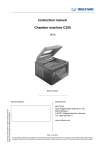
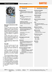
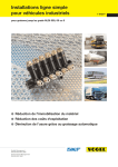
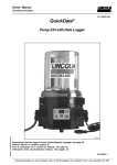
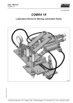
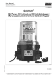
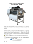
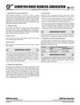
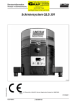
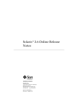
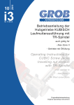
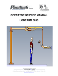
Owner Manual Technical Description 2.1A-30001-H06 Mode of Operation, continuation Check valve The check valve: - closes the pressure line during suction stroke - prevents the lubricant from flowing back to the housing or reservoir 1 2 3 4 R p 1164b95 Fig. 11 - Reservoir with stirring paddle Pump Check valve, spring-loaded Pressure relief valve Return line Pressure line Hydraulic diagram of the pump Arrangement of the pump elements If several pump elements are to be installed, the installation arrangement shown in Fig. 12 must be adhered to. If there is only one pump element , it can be installed in any position. Standard position is no. 3. If there are two elements, install one in position 3 and the other in position 1. 1163a95 Fig. 12 Arrangement of the pump elements Subject to modifications Pump element with adjustable lubricant output The mode of operation (suction and supply phase) is the same as that of the pump elements with an invariable lubricant output. The lubricant outputs are adjustable from 0.04 to 3 3 0.18m /stroke, or 0.7 to 3cm /min. The pump elements are factory-adjusted to the maximum lubricant output; the adjusting dimensions “S” should be 29 ± 0.1 mm. 4158a99 Fig. 13 Adjustable pumpelement Page 14 of 36 LINCOLN GmbH & Co. KG • Postfach 1263 • D-69183 Walldorf • Tel +49 (6227) 33-0 • Fax +49 (6227) 33-259