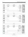
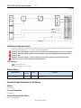
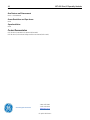
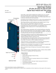
1
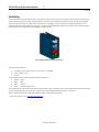
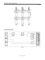
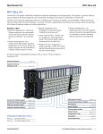
RSTI-EP Slice I/O Specialty Modules EP-5111, EP-5112, EP-5212, EP-5422, EP-5442 GFK-2962 November 2015 Module Status LED Channel Status LED GE provides several RSTi-EP specialty modules, which can be used to meet specific needs in your system. Each module has a Module Status LED and each channel has a LED for visual indication of connectivity. The counter module EP-5111 can read one square-wave signal (1 channel) (for example, from an incremental encoder) with a maximum input frequency of 100 kHz. The 32-bit counter can count up or down within a predetermined range of values. The digital counter module EP-5112 can read two square-wave signals (2 channels) (for example, from an incremental encoder) with a maximum input frequency of 100 kHz. Depending on the operating mode, both 32-bit counters can count up or down independent of each other in a preset range of values. The counters can be controlled via software by setting the appropriate control word. The digital counter module EP-5212 can read frequency of one square-wave signal (1 channel) from one or two external sensors with a maximum input frequency of 100 kHz. Frequencys to be counted are applied to channel CH0 and/or channel CH1, the measurement will be started via control word 1 and 2 respectively. Measuring cycles can be defined in μs. The longer the measuring cycle the more exactly the measurement. The digital pulse width modulation modules EP-5422 and EP-5442 are used for the control of small motors with current requirements of 0.5 A up to 2 A which can also be used for the control of valve flaps. The switching frequencies are adjustable up to 40 kHz and, in addition to this, the push/pull output levels can be used for motor activation; for example: change of rotation direction. As with all modules of the RSTi-EP system, the characteristics are outstanding – from the modular design and the interchangeable electronics to the removable plug-in terminal strip. The RSTi-EP station is usually installed on a horizontally positioned DIN rail. Installation on vertically positioned DIN rails is also possible. Modules should to be allowed to de-energize for a minimum 10 seconds after power down, prior to starting any maintenance activity. Refer to the RSTi-EP Slice I/O User Manual (GFK-2958) for additional information. Refer to the RSTi-EP Power Supply Reference Guide, a software utility available on PME V9.00, for detailed power-feed requirements. Module Features Specialty Module Spring style technology for ease of wiring DIN rail mounted Double-click installation for positive indication of correct installation Compatible for 2 and 3 wire connection 32-bit counter, 24 V DC Counting frequency 100 kHz max (A/B channel, 1/2/4- times sampling or pulse and direction, invertible) Gate input (hardware gate, HW gate), reset input, digital output controlled by an internal comparator Alarm and diagnostic function with μs time stamp Digitally adjustable input filter to suppress interferences(17 filter frequencies gradually adjustable between 3 Hz and 187 kHz) Digital pulse width modulation modules can control from 0.5A to 2A. © 2015 General Electric Company. All Rights Reserved. * Indicates a trademark of General Electric Company and/or its subsidiaries. All other trademarks are the property of their respective owners. 2 RSTi-EP Slice I/O Specialty Modules GFK-2962 Ordering Information Module Description EP-5111 1 Channel High Speed Counter, AB 100 kHz 1 DO 24VDC, 0.5A EP-5112 2 Channel High Speed Counter, AB 100 kHz EP-5212 2 Channel Frequency Measurement, 100 kHz EP-5422 2 Channels PWM Output, Positive Logic, 24VDC, 2.0 A EP-5442 2 Channels PWM Output, Positive Logic, 24VDC, 0.5 A Specifications System Data Data Interface System bus transfer rate Galvanic isolation Inputs Number of counter inputs Type Input filter Low input voltage High input voltage Max. input current per channel Sensor supply Sensor connection Reverse polarity protection Module diagnostics Individual channel diagnostics Counter width Maximum input frequency Latch, gate, reset input Mode of operation Status, alarm, diagnostics Status indicator Process alarm Diagnostic alarm Outputs Number Output Current Reverse polarity protection Module diagnosis Individual channel diagnosis Supply Supply voltage Current consumption from system current path ISYS Current consumption from output current path Iin EP-5111 EP-5112 EP-5212 Process, parameter, and diagnostic data depend on the network adapter used. RSTi-EP System bus 48 Mbps -500 V DC between the current paths 1 2 Incremental encoders and other input characteristics for sensor types 1 and 3 are in accordance with EN 61131-2 Filter time adjustable from 0,01 to 1 ms Yes Yes Pulse and direction / AB mode with 1-, 2-, 4-times sampling <5V > 11 V 3.5 mA Yes 2-wire and 3-wire Yes Yes Yes 32 bits 100 kHz -Pulse and direction / AB mode with 1-, 2-, 4-times sampling 2 -Adjustable between 3 Hz and 187 kHz (333 ms and 5 μs) No -Pulse rising edge Yes, parametrizable Yes Yes Yes, parametrizable Yes --- 1 0.5 A Yes Yes Yes ------ ------ 20.4V – 28.8V 8 mA 35 mA plus output current for the digital output For public disclosure 35 mA 35 mA plus sensor supply current RSTi-EP Slice I/O Specialty Modules 3 GFK-2962 General data Operating temperature Storage temperature Air humidity (operation/transport) Width Depth Height Weight -20°C to +60°C (-4 °F to +140 °F) -40°C to +85°C (-40 °F to +185 °F) 5% to 95%, noncondensing as per IEC 61131-2 11.5 mm (0.45 in) 76 mm (2.99 in) 120 mm (4.72 in) 72 g (2.54 oz) 83 g (2.93 oz) 83 g (2.93 oz) EP-5422 System Data Data Interface System bus transfer rate Outputs Number Type Response time Period duration Max. output current Switching frequency Actuator connection Actuator supply Pulse/period ratio Short-circuit-proof Response time of the protective circuit Module diagnosis Individual channel diagnosis Reactionless Supply Supply voltage Current consumption from system current path ISYS Current consumption from output current path IOUT General data Operating temperature Storage temperature Air humidity (operation/transport) Width Depth Height Weight EP-5442 Process, parameter, and diagnostic data depend on the network adapter used. RSTi-EP system bus 48 Mbps 48 Mbps 2 2 PN output stage PN output stage < 0.1 μs < 0.1 μs 25 μs t o 175 ms (40 kHz to 6 Hz) per channel 0.5 A per channel 2A per module 1A per module 4A Resistive load Resistive load static, 6 Hz to 40 kHz 6 Hz to 40 kHz (min. 47 Ω) (min. 12 Ω) Inductive load Inductive load static, 6 Hz to 40 kHz 6 Hz to 40 kHz (DC 13) (DC 13) Lamp load (12 W) static, 6 Hz to 40 kHz Lamp load (48 W) 6 Hz to 40 kHz 2-wire, 3-wire, 3-wire + FE max. 2 A per plug, total max. 4 A max. 2 A per plug, total max. 8 A 0–100 % PN-switching or P-switching, adjustable Yes < 100 μs Yes No Yes 20.4V – 28.8V 8 mA 40 mA + Load -20°C to +60°C (-4 °F to +140 °F) -40°C to +85°C (-40 °F to +185 °F) 5% to 95%, noncondensing as per IEC 61131-2 11.5 mm (0.45 in) 76 mm (2.99 in) 120 mm (4.72 in) 77 g (2.72 oz) For public disclosure 82 g (2.89 oz) 4 RSTi-EP Slice I/O Specialty Modules GFK-2962 LEDs LED EP-5111 Module Status EP-5112 EP-5212 EP-5422 Green: Communication over the system bus Red: Module System Fault or Diagnostic Fault Yellow: PWM output 0 – 100%, P-switching 1.1 1.2 1.3 1.4 2.1 2.2 2.3 2.4 Yellow: A/pulse controlled Yellow: CH0 A pulse controlled Yellow: B/direction controlled Yellow: output set Yellow: CH0 B direction controlled 3.2 3.3 3.4 4.1 Yellow: PWM output 0 – 100%, P-switching Yellow flashing at 2 Hz: Yellow flashing at 2 Hz: PWM output 0 is > 0 and PWM output 0 is > 0 < 100%, PN-switching or and < 100%, PNP-switching switching or Pswitching Yellow: CH0 active (1-level) Yellow: reset input controlled Yellow: PWM output 1 – 100%, P-switching 3.1 EP-5442 Yellow: latch input controlled Yellow: gate input (HW gate) controlled Yellow: CH1 A pulse controlled Yellow: CH1 B direction controlled Yellow: PWM output 1 – 100%, P-switching Yellow flashing at 2 Hz: Yellow flashing at 2 Hz: PWM output 0 is > 0 PWM output 0 is > 0 and and < 100%, PN< 100%, PN-switching or switching or PP-switching switching Yellow: CH0 active (1-level) 4.2 4.3 4.4 For public disclosure RSTi-EP Slice I/O Specialty Modules 5 GFK-2962 Field Wiring The connection frame can take up to four connectors, and four wires can be connected to each connector. The Spring style technology allows for either finely stranded or solid wire with crimped wire-end ferrules or ultrasonically welded wires, each with a maximum cross-section of 1.5 mm² (16 guage), to be inserted easily through the opening in the clamping terminal without having to use tools. To insert fine stranded wires without wire-end ferrules, the pusher must be pressed in with a screwdriver and released to latch the wire. Connector Block with Four Wire Connectors Connector Specifications: • conductor cross-section 0.14 to 1.5 mm² (26 – 16 guage) • max. ampacity: 10 A • 4-pole The pushers are color-coded for the following connections: • White Signal • Blue GND • Red 24 V DC • Green Functional earth (FE) The modules do not have a fused sensor/activator power supply. All cables to the connected sensors/actuators must be fused corresponding to their conductor cross-sections (as per Standard DIN EN 60204-1, section 12). Refer to the RSTi-EP Slice I/O User Manual (GFK-2958) for additional information. For technical assistance, go to http:/support.ge-ip.com. For public disclosure 6 RSTi-EP Slice I/O Specialty Modules GFK-2962 Connection Diagrams EP-5111 EP-5112 EP-5212 EP-5422 For public disclosure RSTi-EP Slice I/O Specialty Modules 7 GFK-2962 EP-5442 Connection Block Diagrams EP-5111 EP-5111 For public disclosure 8 RSTi-EP Slice I/O Specialty Modules GFK-2962 EP-5112 EP-5112 EP-5212 EP-5212 EP-5422 EP-5422 For public disclosure RSTi-EP Slice I/O Specialty Modules 9 GFK-2962 EP-5442 EP-5442 Installation in Hazardous Areas EQUIPMENT LABELED WITH REFERENCE TO CLASS I, GROUPS A, B, C & D, DIV. 2 HAZARDOUS AREAS IS SUITABLE FOR USE IN CLASS I, DIVISION 2, GROUPS A, B, C, D OR NON-HAZARDOUS AREAS ONLY WARNING - EXPLOSION HAZARD - SUBSTITUTION OF COMPONENTS MAY IMPAIR SUITABILITY FOR CLASS I, DIVISION 2; WARNING - EXPLOSION HAZARD - WHEN IN HAZARDOUS AREAS, TURN OFF POWER BEFORE REPLACING OR WIRING MODULES; AND WARNING - EXPLOSION HAZARD - DO NOT CONNECT OR DISCONNECT EQUIPMENT UNLESS POWER HAS BEEN SWITCHED OFF OR THE AREA IS KNOWN TO BE NONHAZARDOUS. ATEX Marking II 3 G Ex nA IIC T4 Gc Ta: -20°C to +60°C (-4° F to +140 °F) Release History Catalog Number Firmware Version Date EP-5111, EP-5112, EP-5212, EP-5422, EP-5442 N/A Nov-2015 Comments Initial Release Important Product Information for this Release Updates Initial Release Funcional Compatibility Initial Release Problems Resolved by this Release None – Initial Release For public disclosure 10 RSTi-EP Slice I/O Specialty Modules GFK-2962 New Features and Enhancements None – Initial Release Known Restrictions and Open Issues None Operational Notes None Product Documentation RSTi-EP Slice I/O Module User Manual (GFK-2958) RSTi-EP Slice I/O Functional Safety Module User Manual (GFK-2956) GE Intelligent Platforms 1-800-433-2682 1-434-978-5100 www.ge-ip.com For public disclosure