1
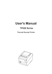
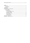
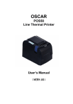
SPRT
®
SP-
-POS88III
Line Thermal Printer
User’s Manual
Beijing Spirit Technology
Development Co, Ltd.
SPRT
Content
Introduction ··························································································2
Chapter 1 Feature and Performance ···················································3
1.1 Print Performance ···························································3
1.2 Print Paper········································································3
1.3 Print Font ·······································································3
1.4 Interface ···········································································3
1.5 Print Control Command ·················································4
1.6 Power Supply ···································································4
1.7 Operation Environment ····················································4
1.8 Outline Dimension ···························································4
1.9 Model Classification ························································4
Chapter 2 Operation Specification ·····················································5
2.1 Printer Appearance···························································5
2.2 Paper Installation······························································5
2.2.1 Paper Loading ··································································5
2.2.2 Solution to Paper Jam·······················································6
2.3 Interface Connection ························································6
2.3.1 Serial Interface ······························································6
2.3.2 Parallel Interface ···························································7
2.3.3 Cash drawer Interface··················································10
2.3.4 Power Connection ·······················································10
2.4 Buttons and Indicators····················································10
2.5 Self-test ··········································································11
2.6 DIP Switch Setting ·························································12
Chapter 3 Print Control Commands ·················································12
3.1 Summary ········································································12
3.2 Command Descriptions ··················································13
3.2.1 Print Commands·····························································13
3.2.2 Line Spacing Setting Commands····································13
3.2.3 Character Print Commands·············································14
3.2.4 Special Control Commands············································16
3.2.5 Graphics Print Commands··············································16
3.2.6 Bar Code Print Commands·············································18
3.2.7 Other Commands ···························································20
Appendix 1 Performance Index ··························································22
Appendix 2 Index of Print Commands················································23
Appendix 3 Index of Print Characters ·················································24
1
SPRT
Introduction
SP-POS88III printer is a new type line thermal printer, it features in
fast speed print, low print noise, high reliability, perfect print quality and
ribbon needless, avoiding the vexation of regular maintenance.
SP-POS88III printer: small in outline dimension, simple operation, and
extensive application, especially suitable for commercial cash register,
PC-POS, bank POS and all kinds of receipts print.
2
SPRT
Chapter 1 Feature and Performance
1.1 Print Performance
●
●
●
●
●
Print method: direct thermal
Print paper width: 79.5±0.5mm
Print density: 8 dots/mm, 576 dots/line
Print speed: approx.150mm/sec. or 40 lines/sec.
Reliability
Print head life: 100km
Using condition:
*Print 12 × 24 ASCII characters, print 50 lines each time, intermittent
print repeatedly
*Each dot-line printing at the same time should not exceed 25%, each
character line and one dot vertical printing repeatedly should
not exceed 11 times
*Use specified thermal paper
Cutter life: 500,000 cuts
Using condition: less than 30 cuts/minute
● Valid print width: 72mm
● Feeding speed: approx.150mm/sec. or 40 lines/sec.
1.2 Print Paper
● Thermal paper roll model: TF50KS-E(Japan paper co.ltd)
AF50KS-E (JUJO THERMAL)
● Thermal paper roll : Width--- 79.5±0.5mm
Outer Diameter --- 80mm(max.)
Inner Diameter--- 13mm(min.)
2
Thickness --- 53~60g/m
1.3 Print Font
● IBM Character set II (ANK):
12×24 dots,1.25(W)×3.00(H)mm;
● GB GB2312-80(Chinese):
24×24 dots,3.00(W)×3.00(H)mm.
1.4 Interface
● Serial interface
3
SPRT
DB-25 socket (female), supports XON/XOFF and RTS/CTS protocols.
Baud rate: 12000~115200bps adjustable.
Data structure: 1start bit + (7 or 8) data bits + 1 stop bit.
Parity checking: no parity or odd, even parity optional.
● Parallel interface
DB-25 socket (male) or 36-pin is optional, 8-bit parallel interface,
BUSY/ACK handshaking protocol, TTL signal level.
● Cash drawer control
DC24V,1A,6-pin RJ-11 socket.
1.5 Print control commands
● Character print commands: support double-width, double height print of
ANK characters, user-defined characters and Chinese characters, the
character line spacing is adjustable.
● Graphics print commands: support the print of bit-map graphics and
download bit-map graphics with different density
● GS bar code print commands: support EAN-13,EAN-8 bar code print.
1.6 Power Supply
● DC24V±10%,2A,A-1009-3P power socket.
1.7 Operation Environment
● Operation temperature: 5~50℃; Relative humidity: 10~80%
● Storage temperature: -20~60℃; Relative humidity: 10~90℃
1.8 Outline Dimension
● 150(W)×192(L)×150(H)mm
1.9 Model classification
Model
Cutter
POS88Ⅲ-AS
Partial-cutting
POS88Ⅲ-AP1
Partial -cutting
POS88Ⅲ-AP2
Partial -cutting
POS88Ⅲ-BS
Full-cutting
POS88Ⅲ-BP1
Full-cutting
POS88Ⅲ-BP2
Full-cutting
Interface
Serial( DB25 female)
Parallel(36-pin standard print)
Parallel(DB25 male)
Serial(DB25 female)
Parallel(36-pin standard print)
Parallel(DB25 male)
4
SPRT
Chapter 2 Operation Specification
2.1 Printer Appearance
Power Indicator (green)
Status Indicator (red)
Paper-end Indicator (red)
Paper Feed Button(feed)
Paper-out Slot
Power Switch
Printer interface
Cash drawer interface
Power socket
Fig.2-1 printer appearance
2.2 Paper Installation
2.2.1 Paper Loading
SP-POS88III adopts 80mm width thermal paper roll.
If you prepare to load the paper, you can do as the following steps.
Hold down the upper cover button, open the movable upper cover, move
away the old paper roll, and put the new thermal paper in the paper holder
of printer, draw a certain length of the paper roll, put the paper end on the
print head, close the upper cover and press it downwards lightly until it
restore to original position, and the paper end appears from the paper-out
slot which is on the upper cover, then print paper installation is finished.
5
SPRT
Caution!
1. When there is no paper in the print head, don’t press 【FEED】
button, avoiding to shorten the print head life;
2. Please don’t feed or draw the paper forwards or backwards with
hands. When returning paper, please cut the extra paper, and press
【LF】button, paper will go forwards.
2.2.2 Solution to Paper Jam
Turn power off, open the upper cover, hold down the black rubber cutter
lever, at the same time move the cutter forwards slowly, can separate the
cutter from the print head. Then lift the print head lever forwards to
maximum position, draw out the paper slowly with hand.
2.3 Interface
2.3.1 Serial Interface
The serial interface of SP-POS88Ⅲ printer is compatible with RS-232C,
supports RTS/CTS and XON/XOFF handshaking protocols, uses DB25
socket (female). The pin order of the serial port is as Fig.2-2 shows:
13
1
25
14
Fig.2-2 Pin Order of Serial Port
The pin assignment of serial interface is shown in Fig. 2-3:
Pin No.
Signal
Source
Description
Name
2
RXD
Host
Printer receives data from host
3
TXD
Printer
Printer transmits control code
X-ON/X-OFF and data to host
5
CTS
Printer
Signal “MARK” indicates that
the printer is “BUSY” and
unable to receive data;
“SPACE” indicates that the
printer is “READY” for
receiving data.
6
SPRT
6
DSR
Printer
Signal “SPACE” indicates that
the printer is “ONLINE”
7
8
GND
DCD
—
Printer
Signal Ground
Same to signal CTS
Note: ①“Source” denotes the source that signal come from;
② Logical signal level is EIA.
Fig.2-3 Pin Assignment of Serial Interface
The baud rate and data structure in serial interface mode is 9600bps, 8-bit
data bits, no parity bit and 1 stop bit.
The serial interface of SP-POS88 Ⅲ can be connected to standard
RS-232CRS-232C interface. When it is connected to IBM PC or its
compatible machine, connection can accord to Fig.2-4.
DSR 6
6 DS R
DSR 6
6 D SR
GN D 7
RT S 5
5 GN D
GN D 7
RT S 5
7 G ND
TX D 3
RX D 2
8 D CD
TX D 3
RX D 2
8 CT S
1 DC D
2 RX D
3 TX D
5 C TS
3 R XD
2 T XD
Printer
IBM PC Serial Printer
IBM PC Serial
25PIN Socket Interface DB-9 25PIN Socket
Interface DB-25
Fig.2-4 Connection between SP-POS88Ⅲ and IBM PC Serial Interface
Sketch Map
2.3.2 Parallel Interface
The parallel interface of SP-POS88Ⅲ printer is compatible with
CENTRONICS, supports BUSY or ACK handshaking protocol, uses DB25
socket (male) or 36pin CENIRONICS socket (female) optional.
The pin order of parallel port is as Fig. 2-5 shows:
Fig.2-5 Pin Order of Parallel Port
7
SPRT
The pin assignment of DB25 parallel interface is shown in Fig. 2-6 shows:
Pin No.
Signal
Direction
Description
1
/STB
In
2
3
4
5
6
7
8
9
DATA1
DATA2
DATA3
DATA4
DATA5
DATA6
DATA7
DATA8
In
In
In
In
In
In
In
In
10
/ACK
Strobe pulse to latch data,
Reading occurs at falling edge.
These signals represent the 1st
bit to 8th bit of the parallel data
representatively, each signal is
at HIGH level when data is
logic 1, and LOW when data is
logic 0.
Out
Answer pulse, LOW level
signal indicates that data have
already been received and the
printer gets ready to receive the
next data.
11
BUSY
Out
HIGH level signal indicates that
the printer is BUSY and can not
receive data.
12
PE
Out
HIGH level signal indicates that
paper is end.
13
SEL
Out
Pulling up to HIGH level signal
by a resistor
15
/ERR
Out
LOW level signal indicates that
there has error.
14,16,17
NC
---
No connection
18-25
GND
---
Grounding logical 0 level
Note: (1)“In” denotes input to the printer,“Out” denotes output from the
printer.
(2)Signal level is TTL standard.
Fig.2-6 Pin assignment of DB-25 parallel interface
8
SPRT
The pin assignment of 36pin parallel interface is as Fig.2-7 shows:
pin No.
Signal
Direction
Description
Strobe pulse to latch data,
1
/STB
In
Reading occurs at falling
edge.
2
3
4
5
6
7
8
9
10
DATA1
DATA2
DATA3
DATA4
DATA5
DATA6
DATA7
DATA8
/ACK
In
In
In
In
In
In
In
In
These signals represent the 1st
bit to 8th bit of the parallel
data representatively, each
signal is at HIGH level when
data is logic 1, and LOW
when data is logic 0.
Out
Answer pulse, LOW level
signal indicates that data have
already been received and the
printer gets ready to receive
the next data.
11
BUSY
Out
HIGH level signal indicates
that the printer is BUSY and
can not receive data.
12
PE
Out
HIGH level signal indicates
that paper running out.
13
SEL
Out
Pulling up to HIGH level
signal by a resistor
32
/ERR
Out
LOW level signal indicates
that there has error.
14, 15, 17, 18, 34, 36
NC
--No connection
16, 19~
GND
--Grounding logical 0 level
30, 33
Note: (1)“In” denotes input to the printer,“Out” denotes output from the
printer.
(2)Signal level is TTL standard.
Fig. 2-7 Pin assignment of 36pin parallel interface
9
SPRT
The timing chart for interface signal of parallel interface is as Fig.2-8
shows:
BU SY
/A CK
DA TA
/S TB
0. 5μS
0. 5μS
0. 5μS
0.5μS
0.5μS
Fig.2-8 Signal Timing Chart of Parallel Interface
2.3.3 Cash Drawer Interface
The cash drawer interface of POS-POS88 Ⅲ adopts
RJ-11 6-pin socket, as Fig.2-9 shows:
Fig. 2-9
Cash drawer interface
The pin assignment of the cash drawer interface
is defined as follows:
Pin No.
Signal
Direction
1
Chassis Ground
--2
Cash drawer driver signal
Out
3
Cash drawer on/off status signal
In
4
5
+24VDC
N.C
Out
---
6
Cash drawer on/off status signal ground
---
2.3.4 Power Connection
SP-POS88III uses the external power supply adopter
as 24V±10%、2A, power socket is A-1009-3P model,
as Fig. 2-10 shows:
2
3 1
Fig.2-10
Power Socket
2.4 Buttons and Indicators
There is one button and three indicators on SP-POS88 Ⅲ printer. 【FEED】
is paper feeding button, the function of its enabling or disabling the button
on/off can be set by print command, when the button is enabled, press
【FEED】 button, then the paper presenting driver starts up and paper fed
10
SPRT
into the printer; release【FEED】 button, paper feeding stops. The green
POWER light is the power indicator, red ERROR light is status indicator, it
is dark when the printer works normally, while it flashes when reporting an
abnormal emergency, as the following form shows:
Error
Indicator status
Description
ERROR
Code (Hex)
Paper
running out
Flash
continuously
Paper is about to out
88H
Print head
uplifted
Flash once and
put out 1.2
seconds
Put down the print head
Print head
overheat
Flash twice and
put out 1.2
seconds
Printer will restore to
normal status
automatically when
the temperature of the
print head drops
Cutter
position
error
Flash thrice and
put out 1.2
seconds
Printer can’t restore,
wait for testing whether
the cutter blocked
paper
82H
81H
A0H
When the assemblies of printer appear the foresaid errors, parallel interface
/ERR pin became “0”signal level, and automatically send one byte
ERROR code through TXD parallel interface, the status of printer can be
transmitted by ESC v command.
Red PAPEROUT light is paper end indicator. When there is no paper in the
print head, the indicator flashes, and sends one byte 84H code through
TXD serial interface, while it goes dark in normal status.
2.5 Self-test
The self-test will check the condition of printer, if the printer prints out the
self-test receipt correctly, it means the printer works normally. Otherwise it
needs to repair.
The self-test will print out the firmware version, interface setting and 128
11
SPRT
ANK characters.
Hold down【FEED】button and turn on the power, then release the button,
self-test begins automatically at this moment.
2.6 DIP Switch Setting
DIP Switch1 is used to set the baud rate and data structure of serial
interface, setting is as Fig. 2-11 shows.
DIP
Function
ON
OFF
1
Baud rate selection
See Fig.2-12
2
3
4
Handshaking protocol
XON/XOFF
RTS/CTS
5
Length of character
7 bits
8 bits
6
7
8
Parity
Yes
Parity checking mode
Even parity
selection
Wrong solution to data
Ignore
receiving
Fig. 2-11 DIP Switch1 Setting
Baud rate(BPS) DIP 1-1
DIP 1-2
1200
2400
4800
9600
19200
38400
57600
115200
ON
ON
OFF
No
Odd parity
Print“?”
DIP 1-3
ON
ON
OFF
OFF
OFF
ON
ON
OFF
ON
ON
OFF
OFF
OFF
Fig. 2-12 Baud Rate Setting
ON
ON
ON
ON
OFF
OFF
OFF
OFF
DIP Switch 2 each bit is reserved bit.
When set DIP switch, it needs to open the small iron plate at the bottom of
the printer.
Chapter 3 Print Control Commands
3.1
Summary
SP-POS88Ⅲ offers ESC/POS print command set.
12
SPRT
Each command is described in following format:
Print command
Function
Format: ASCII:
the standard ASCII character sequence
Decimal:
the Decimal number sequence
Hexadecimal: the Hexadecimal number sequence
Explanation: what the command does and how to use it.
Example: some examples are listed to illustrate the command for better
understanding.
3.2 Command Descriptions
3.2.1 Print Commands
LF
Print and Feed Line
Format: ASCII:
LF
Decimal:
10
Hexadecimal: 0A
Explanation:
Print the content in the buffer and feed paper one line. Only feed paper one
line if buffer is empty.
ESC J
Format:
Print and Feed n Dot Lines
ASCII:
ESC
J
n
Decimal:
27
74
n
Hexadecimal: 1B
4A
n
Explanation:
Print the content in the buffer and feed paper n dot lines. (n/203 inch),
n=0~255.
This command is only valid for current line and will not change the
spacing settings set by ESC 2,ESC 3 commands.
Example:
3.2.2 Line Space Setting Commands
ESC 2
Format:
ASCII:
ESC
Decimal:
27
Hexadecimal: 1B
Explanation:
Set Line Spacing to 1/6 Inch
2
50
32
13
SPRT
Set line spacing to 1/6 inch.
ESC 3
Format:
Set Line Spacing to n Dot Lines (n/203 inch)
ASCII:
ESC
3
Decimal:
27
51
Hexadecimal: 1B
33
Explanation:
Set line spacing to n dot lines. n=0~255.
One dot-line is 1/203 inch for SP-POS88III, that means this command set
the dot-line spacing to n/203 inch. Default n=30.
Example:
3.2.3
Character Print Commands
ESC !
Set Character Print Mode
Format: ASCII:
ESC !
n
Decimal:
27
33
n
Hexadecimal: 1B 21
n
Explanation:
ESC !n is a comprehensive command to set character print mode, is used
for selecting print character size. Each bit of print parameter n is defined:
× × D5 D4 × × × ×
1: Double Height Print
1: Double Width Print
Default n=0, that means no character enlargement.
ESC SO
Set Double Width Character Print
Format: ASCII:
ESC
SO
Decimal:
27
14
Hexadecimal:
1B
0E
Explanation:
All characters following this command on the same line are printed at
twice their normal width, this command can be deleted by a carriage return
or DC4 command.
14
SPRT
ESC DC4
Cancel Double Width Character Print
Format: ASCII:
ESC DC4
Decimal:
27
20
Hexadecimal: 1B
14
Explanation:
After carrying out this command, the characters will be printed with
normal width.
ESC %
Format:
Select/Cancel User-defined Characters
ASCII:
ESC
%
n
Decimal:
27
37
n
Hexadecimal: 1B
25
n
Explanation:
When n=1, select user-defined character set; When n=0, select internal
character set.
Default n=0
ESC &
Define Use-defined Characters
Format: ASCII:
ESC & s n m [a [p]s×a]m-n+1
Decimal:
27 38 s n m [a [p]s×a]m-n+1
Hexadecimal: 1B 26 s n m [a [p]s×a]m-n+1
Explanation:
ESC & is used to define user-defined characters. s=3,32≤n≤m≤127,
0≤a≤12, 0≤p≤255,
◆ s is the number of bytes in vertical direction, s=3 here.
◆ n is the starting ASCII code of user-defined character.
◆ m is the stopping ASCII code of user-defined character.
When define only one character, n=m, the maximum number of
user-defined characters is 96.
◆ a is the number of dots in horizontal direction.
◆ p is the data of self-defined characters, there are s×a bytes in each
character, the total number of user-defined characters is m-n+1.
◆ User-defined characters are valid until re-defined, reset or power off,
format of the user-defined characters is shown as follows:
15
SPRT
3.2.4
Special Control Commands
ESC c 5
Format:
On/Off Switch Button Function
5
n
53
n
35
n
ASCII:
ESC c
Decimal:
27
99
Hexadecimal: 1B
63
Explanation:
When n=1, button【FEED】is enabled;
When n=0, button【FEED】is disabled;
Default n=0.
3.2.5 Graphics Print Commands
ESC *
Format:
Set Bit-map Graphics Command
*
m
n1 n2
[d]k
42
m
n1 n2
[d]k
2A
m
n1 n2
[d]k
ASCII:
ESC
Decimal:
27
Hexadecimal: 1B
Explanation:
Select bit-map command, m for setting bit-map mode; n1, n2 for setting
number of dots; [d]k for setting contents of bit-map.
M=0,1,32,33, n1=0~255. n2=0~2. d=0~255.
k=n1+256×n2 (m=0,1)
k= (n1+256×n2) ×3 (m=32, 33)
◆ The number of horizontal dots of the graphics is n1+256×n2
◆ If the number of dot is more than one line, the extra portion will be
ignored (referring the following table)
◆ d is the bit map data, for 1 of bit means the related dot will be printed
and for 0 of bit means the related dot will not be printed. (k is the total
number of dot)
◆ m is the selected bit map mode.
16
SPRT
Vertical
Dot
Density
M
Mode
0
8-dot single
density
8-dot double
density
24-dot single
density
24-dot double
density
1
32
33
Horizontal
Density Max. Dots
8
68DPI
101DPI
288
8
68DPI
203DPI
576
24
203DPI
101DPI
288
24
203DPI
203DPI
576
GS /
Format:
Print download bit map graphics
/
n
47
n
2F
n
ASCII:
GS
Decimal:
29
Hexadecimal: 1D
Explanation:
This command is used to print download bit-map graph. n=0~3
◆ n is the print mode of bit-map graph selection.
◆ To define download bit-map graph using GS * command:
N
Bit map
Vertical density
0
1
Normal
Double width
203DPI
203DPI
Horizontal
density
203DPI
101DPI
2
Double height
101DPI
203DPI
3
Double height
and double width
101DPI
101DPI
17
SPRT
GS *
Format:
Define Download Bit-map Graphics
*
n1
n2
[d]k
42
n1
n2
[d]k
2A
n1
n2
[d]k
ASCII:
GS
Decimal:
29
Hexadecimal: 1D
Explanation:
This command is used to define download bit-map graphics.
n1=1~48,n2=1~255,n1×n2<1200, k=n1×n2×8。
◆ d is the bit-map data.
◆ The horizontal size of this graphics is n1×8 dots, and vertical size is
n2×8 dots.
◆ The definition is valid until re-define, power off or system reset. Format
of the download bit-map data is shown as follows:
3.2.6 Bar Code Print Commands
GS W
Format:
Set Bar Code Width
ASCII:
GS W
Decimal:
29 87
Hexadecimal: 1D 57
Explanation:
n1: bar code narrow bar width, unit:
1/203 inch or 0.125mm.
Default n1=3.
n2: bar code broad bar width
GS k
Format:
n1
n1
n1
dot. Each dot for SP-POS88III is
ASCII:
GS
k
Decimal:
29
107
Hexadecimal: D
6B
Explanation:
n--- Select the printing bar code system:
n
2
3
n2
n2
n2
Print Bar Code
n [d] NUL
n [d]
0
n [d]
00
Bar code
EAN-13
EAN-8
18
SPRT
Pay attention to the specified character number of each bar code. EAN-13
and EAN-8 can generate parity characters automatically.
[d]is the printing bar code data.
NUL denotes GS K command is over,and carry out bar code print.
GS H
Format:
Select/cancel Printing HRI Characters
GS
H
n
29
72
n
1D
48
n
GS h
Format:
Set Bar Code Height
GS w
Format: ASCII:
GS
w
Decimal:
29
119
Hexadecimal: 1D
77
Explanation:
Set the width of printing bar code.
n=1~4. When n is different, the width of
shows in the following tab:
Set Bar Code Width
ASCII:
Decimal:
Hexadecimal:
Explanation:
n=0,don’t print HRI characters. Default n=0.
n=1,print HRI characters under bar code print.
ASCII:
GS
h
n
Decimal:
29
104
n
Hexadecimal: 1D
68
n
Explanation:
Set height of bar code to be printed.
n=0~255, its unit is dot. When n=0, it is 256 dots.
Each dot for POS88Ⅲ printer is 1/203 inch or 0.125mm.
Default n=60.
n
1
2
3
4
Narrow size
1
2
3
4
n
n
n
bar code will be different, as
Broad size
3
5
7
9
19
SPRT
Its unit is dot. Each dot for SP-POS88III is 1/203 inch or 0.125mm.
Default n=3.
3.2.7 Other Commands
ESC @
Initialize Printer
Format: ASCII:
ESC
@
Decimal:
27
64
Hexadecimal: 1B
40
Explanation:
ESC @ command is to initialize the following contents of the printer:
·Clear the data in the print buffer;
·Restore the default of each print command
·Select character print mode;
·Delete user-defined characters.
ESC p
Cash Drawer Control
Format: ASCII:
ESC
p m
nl
n2
Decimal:
27
112 m
nl
n2
Hexadecimal: 1B
70
m
nl
n2
Explanation:
This command is to generate a pulse to trigger the opening and closing of
the cash drawer, n1, n2 define the duration of the trigger pulse.
m=0,0<nl≤n2≤255.
Opening time is nl× 2ms, Closing time is n2× 2ms.
ESC v
Format:
Transmit Status of Printer
ASCII : ESC
v
Decimal:
27
118
Hexadecimal: 1B
76
Explanation:
Send printer status to the host.
When printer received the command, it transfers one byte through TXD
serial interface. Definition of said byte is shown as below:
Bit
Function
Value 0
Value 1
Print head
Print head
0
Normal
temperature
overheat
Print head
1
Press down
Put up
position
2
Paper tester
With paper
Without paper
20
SPRT
4
Paper running
out
Not in use
5
Cutter position
6
7
Undefined
Undefined
3
ESC u
Format:
With paper
0
On original
position
---
---
Paper running
out
0
False position
---
---
Transmit Status of Equipment
u
n
117
n
75
n
ASCII:
ESC
Decimal:
27
Hexadecimal: 1B
Explanation:
Send the peripheral equipment status to the host:
Default n=0
When printer received this command, it transmits one byte through TXD
line of the serial interface to the host.
Bit
Function
Value 0
Value 1
0
Cash drawer
on/off signal
level
Low
High
1
2
3
4
Undefined
Undefined
Undefined
Not in use
---
---
---
0
---
---r
---
0
5
Cutter position
---
---
6
7
Undefined
Undefined
---
---
---
---
GS V
Paper cutting
Format: ASCII:
G
S
u
m
Decimal:
29
86
n
m
Hexadecimal: 1D
56
n
m
Explanation:
Printer carries out cutting paper operation once. n=0, n=1 or 49 is for
cutting paper immediately, the said ways needn’t to specify m. When n=66,
should feed paper the number of dot lines set by m, then cut paper,
0≤m≤255. Each dot for SP-POS88Ⅲ printer is 1/203 inch or 0.125mm. It
21
SPRT
can realize whole cutting or half cutting through changing the cutter.
Appendix 1 Performance Index
·Print method: Direct thermal
·Print width: 79.5 ± 0.5mm
·Valid print width: 72mm
·Print density: 8 dots/mm, 576 dots/line
·Print speed: Approx.150mm/sec.or 40 lines/sec.
·Reliability:
Print head life: 100km
Using condition:
* Print 12 × 24 ASCII characters, print 50 lines each time, intermittent
print repeatedly
* Each dot-line printing at the same time should not exceed 25%, each
character line and one dot vertical printing repeatedly should not
exceed 11 times
*Use specified thermal paper
Cutter life: 500,000 times
Using condition: less than 30 times/minute
·Thermal paper roll model: TF50KS-E(Japan paper co.ltd)
AF50KS-E (JUJO THERMAL)
·Thermal paper roll
Width--- 79.5±0.5mm
Outer Diameter --- 80mm(max.)
Inner Diameter--- 13mm(min.)
2
Thickness --- 53~60g/m
· Print Font
IBM Character set II (ANK):
12×24 dots,1.25(W)×3.00(H)mm;
GB GB2312-80(Chinese):
24×24 dots,3.00(W)×3.00(H)mm.
·Serial interface
DB-25 socket (female), supports XON/XOFF and RTS/CTS protocols.
Baud rate: 12000~115200bps adjustable.
Data structure: 1start bit + (7 or 8) data bits + 1stop bit. Parity is optional.
·Parallel interface
DB-25 socket (male) or 36-pin is optional, 8-bit parallel interface,
BUSY/ACK handshaking protocol, TTL signal level.
·Cash drawer control
22
SPRT
DC24V,1A,6-pin RJ-11 socket.
·Power Supply
DC24V±10%,2A,A-1009-3P power socket.
·Operation Environment
Operation temperature: 5~50℃; relative humidity: 10~80%
Storage temperature: -20~60℃; relative humidity: 10~90℃
Appendix 2 Index of Print Commands
Command name
Print commands
Command
LF
ESCJ
Line spacing setting
ESC2
commands
ESC3
Character
commands
print
ESC!
Set character print mode
ESC SO
ESC&
Set double width character print
Cancel double width character
print
Select/Cancel
User-defined
Characters
Define user-defined characters
ESC c 5
On/Off switch Button function
ESC*
Print bit-map graphics
ESC DC4
ESC%
Special
commands
Graphics
commands
control
print
GS/
GS *
Bar
code
commands
print
Description
Print and feed line
Print and feed n dot lines
Set character line spacing to 1/6
inch
Set line spacing to n dot lines
(n/203 inch)
Print
download
graphics
Define
download
graphics
GS W
Set bar code width
GS H
Select/cancel
characters
GS h
Set bar code height
GS k
Print bar code
bit-map
bit-map
printing
HRI
23
SPRT
Other commands
GS w
Set bar code horizontal size
ESC @
Initialize printer
ESCp
Cash drawer control
ESCv
Transmit status of printer
ESC u
Transmit status of equipment
GS V
Paper cutting
Appendix 3 Index of Print Characters
24