1
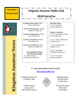
South West RAYNET Association Representing all Radio Amateur Emergency Network groups throughout the South West of England Raynet Data Operations Guide Version 1.4.2 – 17 May 2012 By Ian Harley, G6BJJ South West Raynet Association Data Working Group. Table of Contents 1. PREPARATORY..................................................................................................................................3 1.1 Computer..............................................................................................................................3 1.1.1 Choice of hardware..............................................................................................3 1.1.2 Sound...................................................................................................................4 1.1.3 Raynet Folder…...................................................................................................4 1.2 Data Interface………………................................................................................................4 1.2.1 G4ZLP Digimaster Minipro and Pro+…………………….……………….....4 1.2.2 Tigertronics Signalink USB……………………...…………………….……..5 1.3 Radio ....................................................................................................................................6 1.3.1 Data mode............................................................................................................6 1.3.2 CAT interface......................................................................................................6 1.3.3 RF Power level....................................................................................................6 1.4 Fldigi Software ....................................................................................................................6 1.5 Testing .................................................................................................................................7 2. OPERATIONS......................................................................................................................................8 2.1 Fldigi usage...........................................................................................................................8 2.2 Example of a CHALETS template. ......................................................................................8 2.2.1 Macro use order…...………………………………….....………………….…………..9 3. POSTOPERATIONS.........................................................................................................................................10 3.1 General…….…….………………………………………...……..…………….…..……10 3.2 Signal Logs………………………………………...………………….……….…..……10 4. RESOURCES......................................................................................................................................10 5. Appendix.............................................................................................................................................11 5.1 ICE Macros.........................................................................................................................11 5.1.1 Macro Button Symbols…………………………………….…………….….11 5.2 Radio Rear Panel Connectors.............................................................................................12 5.3 Updating Fldigi…..………………………………………………………….………….12 5.4 G4ZLP Digimaster & Digimaster Pro+ connections…..…….……………....…………12 5.4.1 Digimaster Minipro…………………………………………………………13 5.4.2 Digimaster Pro+……………………………………………………………..13 5.4.3Internal PTT Link………………………………..………………………….14 5.5 Tigertronics Signalink USB…………………………………………………………….14 Page 2 of 14 Introduction This document aims to describe how a Raynet member should prepare for and use data modes during RAYNET operations This document draws heavily on the “Fldigi Operating Guide” prepared by the late Mike Sloan GU3WHN (RAYNET Controller Bailiwick of Guernsey), which was updated for ICE9 by G8RXA and G6BJJ and on the guide written by Nick Johnson 2E0NRJ for Exeter ARS RAYNET's choice of computer operating system, software applications, data interface and radios. Full credit for the scope and detail of this guide is due to them. Before a RAYNET member attends an exercise they should run through the PREPARATORY Section. This will ensure a minimum of set-up and testing time in the field. Once in the field for the event, the member should follow the OPERATIONS information. Finally the member should archive and clean up using the POST-OPERATIONS information. 1. PREPARATORY This document assumes that participating members are using the following devices: 1. Portable computer using the Windows (7/Vista/XP) operating system. 2. The latest Fldigi software program. (Will also run under Linux and other o/s) 3. G4ZLP Digimaster Minipro, Digimaster Pro+, Tigertronics Signalink USB data interface and associated cables or similar. 4. UHF/VHF transceiver. (Note: Do not use the CAT interface.) Before attending an event it is essential to assemble and test the hardware, cabling and software and To learn to use the Fldigi software. This Preparatory section explains how to “get started” assuming you may not have used any of these devices before. Some points: Operation is primarily on VHF and UHF. HF especially NVIS is also feasible but not covered here. A single frequency is used on VHF/UHF with a Controller determining the use of that frequency. At any time voice conversations OR data bursts can be heard between the Controller and members. This technique is a standard and has evolved to minimize the number of stations required on a net. 1.1 Computer 1.1.1 Choice of hardware You will need to have a laptop or netbook computer running a recent version of the Microsoft Windows operating system. The computer should have at least two USB sockets and audio jacks for Microphone In and Headphones Out. The Digimaster’s use the computers sound card and requires these two audio sockets. The Tigertronics Signalink USB has an internal soundcard and does not require the audio input & output lines, instead it uses the USB port. Although the programs do not require fast processors and large memory, newer laptops or netbooks have a battery life of over 4 hours which is very useful in the field. If you use an older, slower computer with Windows XP or Vista, you may be slowed down with installation problems. The most recent version of Windows (Windows 7) is the easiest to configure. The latest operating system version is easiest to use, so the faster you will be using the software. Make sure you are connected to the Internet because during installation as you will need to download applications and reference files, which is not possible once you are in the field. Page 3 of 14 1.1.2 Sound You must understand how your computer processes audio. You will need to recognize and use the names of the individual subsystems for recording audio and playing it back. Audio can be recorded using a microphone built into the front of the laptop computer, or using an external USB webcam or from a 3.5 mm audio jack on the edge of the computer. Audio can be played back through internal loudspeakers or through a 3.5 mm audio jack on the side of the computer. The exact menus and their options are very dependent on whether you are using a standard audio interface or an additional sound card. For a basic laptop with no attached webcam, follow these instructions: 1. 2. 3. 4. 5. 6. 7. 8. 9. 10. 11. 12. 13. 14. If you are using a USB sound card, plug it in and wait for Windows to configure it by monitoring the pop-up messages from the System Tray. Right-click on the “Speaker” icon in the System Tray and select “Recording Devices”. A Microphone should be listed. Make a note of what it is called, e.g. “Realtek High Definition Audio”. (This phrase will be used later in the Fldigi configuration.) Click on the “Microphone” and then click on “Properties”. Under the “Listen” tab, make sure “Listen to this device” is not selected. Under the “Levels” tab, slide Microphone” to 100% and set Boost to 0 db. Under the “Enhancements” tab, ensure “Disable all sound effects” is ticked. Click OK. You are returned to the “Recording” tab. Now click on the “Playback” tab. Make a note of the name of the “Speakers”. Usually it is the same as microphone (e.g. “Realtek......”) (This phrase will also be used later in the Fldigi configuration.) Click on “Levels” and make sure the main audio slider is 100%. If there is a slider for “Microphone”, click on the small speaker icon to Mute it. Important: Click on the “Enhancements” tab and ensure “Disable all sound effects” is ticked. Press “OK”. You are now back in the “Sound” screen. Click “OK”. Reboot the computer. 1.1.3 Raynet Folder 1. 2. 3. 4. Create a folder in which to keep all RAYNET related documentation and forms. Right-click on the Desktop and select “New” → “Folder”. Change the name to “RAYNET Data Files”. Double click on the “RAYNET Data Files” and in the empty folder create the following folders using the same sequence: “Documentation”, “macros”, “Pending Files”, “Received Files”, “Templates Copy” and “Transmitted Files”. Using the weblink in the Resources section at the end of this document, download the “CHALET Text Form Master.txt” into the “Templates Copy” folder. Also download the latest “ICEmacros_v(x).mdf” file into the “\fldigi.files\macros” folder. 1.2 Data Interface The main interfaces considered are the G4ZLP Digimaster Minipro and Pro+ series and the Tigertronics Signalink USB. Other interfaces are available, but due to their number are not covered here, as the two above have been tried and tested extensively by the SWRA Data Working group and have found to be reliable and simple. Careful reading and following of the manufacturer’s instructions manual is taken for granted, however some additional tips are given below. 1.2.1 G4 ZLP Digimaster Minipro & Digimaster Pro+ The documentation for the Digimaster series can appear bewildering as it does not clearly specify the functions of the unit. Instead it describes in great detail its versatility and vast number of protocols and radios that it works with. The device essentially provides isolated interfaces for the audio input/output which gets around awkward earthing problems when using a computer and radio both connected to the same earth. It also adds a USB interface to control PTT keying. A useful feature is the CAT interface that allows simple remote control of the radio from Fldigi (or Ham Radio Deluxe or Digipan). However this is not compatible with Raynet operations. Inspect the Digimaster (Pro+) unit, rear connectors and Page 4 of 14 cables. Correct installation appears difficult because there are no socket labels, however by looking at the following diagram copied from the Digimaster’s instructions, you will see that there is only one way to connect the unit. The following instructions are adapted from the instructions referred to in the Resources appendix at the end of the document “Digimaster Pro+ Installation” ©G4ZLP Electronics 2011. For the Digimaster Pro+… (for the Digimaster MiniPro jump to step 3) 1. Place the Digimaster Pro+ so that the power push-button is on the left. Push its power button in. 2. Set the two front panel controls (transmit and receive level) to the 9 o'clock position. 3. Attach the USB cable from the computer to the Digimaster. 4. Windows should identify the Digimaster and use the correct drivers to enable the interface. When Windows has configured the port the red LED indicator on the Digimaster Pro+ flashes red/green three times. The LED when green indicates power is on and the interface is in receive. When red, the LED indicates TX, either DATA or CW. 5. See the Resources page in this document appendix and download the “Digimaster Pro+ Com Port Test” program. It will download an executable program called “Find Digimaster PRO” into your Downloads folder. 6. Double click on this downloaded program. Click “OK” or “Yes” to any pop-ups about security. A small application opens with a single “Find” button. 7. Click on the “Find” button and wait 20 seconds while the program scans up to 96 virtual COM ports. When it completes it reports on two COM port interfaces with information such as a. “COM 8 G4ZLP Digimaster PRO+ PTT/FSK/CW port” and b. “COM 9 G4ZLP Digimaster PRO+ CAT port + LOOPBACK”. 8. Make a note of the exact COM port numbers, which will be needed when Fldigi is configured. 9. Attach the audio cable from the computer to the Digimaster. Take care to align the arrow on the connector housing with the top of the unit. It is a tight fit on the Digimaster Pro+. 10. Attach the cable from the Digimaster to the Radio. The appendix to this document contains a copy of the standard Mini-DIN layout for most radios. On the Digimaster Minipro jump to step 13 11. Attach the (CW) PTT cable from the computer to the Radio. 12. If the Radio has a CAT interface, it is recommended that you do not connect or use the CAT cable. Take care to align the arrow on the connector housing with the top of the unit. It is a tight fit on the Pro+. 13. This completes the Digimaster installation. 1.2.2 Tigertronics Signal Link USB The Tigertronics Signalink USB is very similar in operation and set-up to the Digimaster Pro+. It has an on-board Sound Card with level controls on the front panel, plus a delay control to ‘hold’ Tx/Rx actions. All audio connections to the computer is via the USB line. See Appendix 5.5 for more detail. A major difference however is that the Signalink USB has an internal series of jumpers which must be configured for each radio. The exact settings for each radio must be determined by reference to the Tigertronics Signalink USB website. www.tigertronics.com/sl_wirebm.htm or the product CD The following instructions are adapted from the instructions referred to in the Resources appendix at the end of the document. 1. 2. 3. 4. 5. 6. Place the Signalink USB so that the power push-button is on the left. Push its power button in. Set the three front panel controls (transmit, receive and delay level) to the 9 o'clock position. Attach the USB cable from the computer to the Signalink USB and power on the Signalink. Windows should identify the Signalink and use the correct drivers to enable the interface. The green LED when indicates power is on and the interface is in receive. The red LED indicates TX, either DATA or CW. Locate the correct COM port by using a test program or in the computer’s Hardware manager. It reports on a COM port interfaces with information such as: “COM 4 Signalink USB port” Make a note of the exact COM port numbers, which will be needed when Fldigi is configured. Page 5 of 14 7. Go to the Audio Device manager on your computer. You should now see a new audio Communications device. Enable this device and mute all other input and output lines. Set this as the default for communications. 8. It is possible to monitor the audio via the Speaker socket on the back of the Signalink USB. 9. Attach the cable from the Signalink USB to the Radio. The appendix to this document contains a copy of the standard Mini-DIN layout for most radios. 10. This completes the basic Signalink USB installation. 1.3 Radio 1.3.1 Data mode For the purpose of the RAYNET exercise on VHF/UHF, data modes will be used on the same frequency as audio, so there is no need to change the “Mode” away from FM. (On HF operation, you would change to use “DIG” mode.) But the baud rate and connections must be set to 1200bps. 1.3.2 CAT interface It is strongly recommended that you do not use the CAT interface for Raynet data operations at VHF/UHF, due to conflicts with some operational parameters. If you are using the CAT interface, (i.e. for non-Raynet work), you must make sure your radio is correctly configured. Use the configuration buttons on the radio to set the CAT interface speed and assignment per the user manual. 1.3.3 RF Power level Data modes need to operate over a linear part of the power amplifier in the transmitter. Therefore, do not run the RF Power level at 100% as this will distort the audio frequencies leading to garbled data transmission and resulting in over-modulated distortion. Set the RF power level to about 40% of the maximum rating of the transmitter. e.g. 40W on a 100W rated transmitter. 1.4 Fldigi Software Fldigi software is an ‘encapsulating environment’ , i.e. a suite of software. However the Fldigi software ranks as one of the most reliable and versatile of the data mode applications. As there are so many data modes (over 60), there are many options to support, so when looking at the program user interface for the first time it can be daunting. Before going any further, read more about the program on its Wiki page references in the Resources page as “Fldigi user guide”. 1. 2. 3. 4. 5. 6. 7. 8. 9. Download the latest stable Fldigi application from the reference in the Resources page for “Fldigi downloads”. If you have a previous version of Fldigi it is important that this is completely uninstalled, prior to loading a new version using an uninstaller and registry cleaner such as REVO. Run the downloaded program answering “Yes” to all the questions. When installation is complete, locate the new Fldigi icon and double click to start the program . Fldigi uses a folder of customized information called “fldigi.files” in your ‘Users’ directory. If this is the first time the program has been run, it will ask questions about you and your computer to start creating these customised files. A set of “wizard” screens will request information from you. Under “Operator Information”, enter your Call Sign, Name, QTH and Locator as they are required by the ICEmacros. You can leave the Antenna fields blank unless you plan on doing HF data modes with other hams. Click “SAVE”. Under “Audio Drivers” → “Devices”, select “Port Audio”. Remembering the names of the audio devices you noted in the Computer Sound setup, use the drop-menu arrows to select those names for “Capture” (Recording) and “Playback”. Click “SAVE”. There is nothing to alter under the other two tabs (Settings and Tx. Level”, so click “Rig”. The “Rig” screen has five tabs. Commence with “Hardware PTT”. Click on “Use Separate PTT” Select appropriate COM port for the PTT/FSK/CW port you recorded earlier. Set Use both RTS and DTR. The Initialize button will go red. Click “Initialize” to activate the port. Click “SAVE” Click on “SAVE”. Page 6 of 14 10. The Wizard ends and the Fldigi program start running. 11. Click on “File” → “Exit”. When asked to save the configuration information, click on “Save”. 12. In your “Users” folder there is now a customised “fldigi.files folders containing the information you have entered. 13. Start Fldigi again. 14. If you have not already done so, download the latest SW Raynet Fldigi macro file ICEmacros_v(x).mdf (~4kb) that contains definitions for each of the F1 to F24 macro keys. The weblink is in the Resources section near the end of this document. A full explanation of these appears in the Appendix. 15. Move the file to the folder: “C:\users\%name%\fldigi.files/macros”. 16. In Fldigi, click on “File” → “Macros” → “Open”. Change to the above folder and select “ICEMacros_v(x).mdf”. The new macro bar should now appear as shown on page 10 of this guide. Click on “Configure” → “User Interface”. Select the “Macros” tab. 17. Enable the last two options on the page “Load last used macro file on start-up” and “Display macro file name on start-up”. 18. Click on “Configure” → “Misc” → “Sweet Spot”. Make sure all the values are set to “1000”. This is the default offset of 1 kHz for each data mode. 19. Click on “ID” set the “Pre-Signal Tone” to 3 seconds. This sets a 3 second delay to allow any talkthrough units or repeaters to latch. Click “Save” 20. Click on “Waterfall” → ”Display”. Click on “Always show audio frequencies” to enable it. 21. Click “Save” and “Close”. 22. If you want to change the size of characters displayed by Fldigi, use “Configure” → “Colours and Fonts”. You can use this to increase the size of received text, for example. Click on “Close”. 23. Slide the cursor to 1000 Hz on the waterfall and then click on the “Lk” button under the display to hold it at that value*. You can fine tune the value using the adjacent arrow keys. A single arrow changes the value by 1 Hz and the double arrow by 10 Hz. Do not use the AFC. 24. At the base of the screen ensure the waterfall signal range settings are set to “- 20” dB and to 70 dB for the signal range. You can alter the values with the adjacent arrow keys. 25. At the bottom right of the screen is a slider control to adjust squelch (ALC). Slide it to between one third to half way up depending on signal strength received. Too low a setting introduces random characters. Too high a setting can lose data. 26. Select the correct data mode to use. Click on “Op Mode” → “NBEMS modes” or “BPSK” → “BPSK250”. Raynet Control may later request this be changed should propagation conditions be un/favourable. To typically BPSK500 or BPSK125 or even down to BPSK31 27. Click on “File” → “Exit”. 28. Start Fldigi again and ensure a message confirming the loading of the ICEmacros_v(x).mdf file has been completed. 29. *If you change the mode at any time, you will need to apply the “Lk” button again 1.5 Testing To start testing, disconnect cables between the Data Interface and the radio. This will stop you accidentally sending bursts of tone data when you were not planning to do so. If your laptop has a headphone socket, you can remove the audio jack and listen to the generated BPSK audio through the laptop loudspeaker. This is a good test to ensure that you have correctly configured Fldigi audio. Similarly if the laptop has a built-in microphone you can use it to pick up sounds that are randomly displayed as noise on the waterfall display. Make sure that both Receive and Transmit windows are clear. Right-click in each window for the drop down menu in each window to achieve this. Enter the group or operators name, call sign and location of the Raynet Control in the logging window at the top of the screen. Play a macro by clicking on the Macro 2 button ([My ID]). Text will appear in the “Transmit” window and a burst of tone through the laptop loudspeaker will be heard. While this tone is playing you should hear a click from the data interface implying it would be generating the PTT for the transmitter*. If this does not happen, it is best to call another Raynet member and talk through your tests. Assuming the audio could be heard, then you are ready to proceed. Connect the leads from the Digimaster to the radio. Page 7 of 14 *Some radios, especially handhelds require a link to be closed on the circuit board. See section 5.4 below. 2. OPERATIONS 2.1 Fldigi usage Operation is on VHF/UHF within the Zone and generally BPSK mode is used, although any data mode could be employed. A one-to-one exchange with control is assumed but the procedure is equally capable of outstations sending data to each other, as long as Control is actually in control of the net to avoid confusion and interference. All links will be established prior to turning the net over to data. Each station with data to transmit must first notify Control and await clearance. The rest of the net is placed on standby during the transmission of the data. Data for transmission must be recorded although not necessarily on paper. It must however be capable of being printed out in hard copy form. This must be filed for legal reasons. This will typically be a CHALETS/Message Pad text file. 1. 2. 3. 4. 5. 6. Prepare this data file while you are off-air. Open the “Raynet Data Files” folder on your Desktop, open the “Templates Copy” file. Right click on “CHALETS Text Form Master” and select “Open With” →“Notepad” (do not use “WordPad” or “Word” as these add unwanted formatting characters.) Edit the form with the data on the submitted message form. You will note that it reflects exactly the fields on the approved CHALETS form using the alpha numeric identity of the items rather than the text titles. “Save As” the file into the “RAYNET Data Files” → “Pending Files” folder. Save it as a separate Text File in a suggested format of either a. <call sign>Serial#.txt i.e. g4wdr0022.txt or b. <call sign>DTG_Serial#.txt i.e. g4wdr102030_001.txt Close the file. An example CHALETS text form for Data transmission via RAYNET is shown below. 2.2 CHALETS TEXT FORM for Data transmission via RAYNET From: To: Info: CEPO CEPO Location: DORCHESTER Location: PLYMOUTH DTG:102030 A Incident: ICE9 Serial #:001 C: 1: 100 2: 3: H: 4: 5: 6: NO 7: 8: A: 9: 10 : 11: YES L: 12 : 13: 14: 40 E: 15: 16: 17: 18: T: 19: TRAIN 20: S: 21: 22: ________________________________________________________________________________ Sent DTG: 102035 A By: G8RXA You should now prepare to go on-air. Page 8 of 14 On the main Fldigi screen enter the receiving station (RAYNET Control) call sign, location and name details. Note that the [VOX] button is used to alert others that voice communications are required as most stations will have their speaker muted. 2.2.1 Use the ICE Macros in this order… 1. 2. 3. 4. 5. 6. 7. 8. 9. 10. 11. 12. 13. 14. 15. 16. [Tuning], [My ID] … this logs you as “On Net” with control. Even centering everyone's Waterfall to the same location it will still be necessary to send a transmitted test tone for participants to 'net in' owing to a degree of uncertainty with individuals radio frequency settings. Control should reply with [Ack Message]. [Msg 4U] … this sends a Tx request to Control/other station. When given the go ahead to send, [Send ur Msg], click macros in this order… [Start of Message], [DTG] – this puts correct headers on the message for you. Place cursor below last entry in the Tx window, Right click, “Insert File”. Scroll to your preprepared completed CHALETS TEXT File in “RAYNET Data Files” → Pending Files”. The text is automatically pasted into the window. Scroll to the bottom of the lower (Tx) window - Check the accuracy of the data. Check the accuracy again !!! Make absolutely sure that the cursor is at the end of the file. Check again that the recipient's call sign and location has been entered in the top logging window. Click on the [End of Message] macro button. All the above macro's and file content is now transmitted. The file will appear to transmit to the top window at this point. Ensure all data has been copied and remember that the cursor must be at the end of the edited file before transmission. If not, only partial data will be sent. The radio returns to receive. Once the file has been transmitted, wait for confirmation message from Control that the file has been received [Ack Message]. Be prepared to re-transmit, [Say Again]. If OK, save the transmitted data in the upper window by highlighting the text to be saved then using right click to bring up the menu, i.e., “Save to file” Choose the “Raynet Data Files” → “Transmitted Files” folder and save the file using a unique file name appropriate to the operation. Clear both windows of all data. Right Click “Clear” At Raynet Control, the Controller will also right click on the file he has received and save it in a relevant folder using a unique file name. A hard copy may be printed at Control to enhance the audit trail. Repeat this sequence as necessary. Clear both windows of all data before preparing a new message! If you find you have made a mistake in sending data or the transmitter “locks On” you can perform an emergency transmit stop and force FLDigi and the radio back into receive mode by pressing the macro button [ Tx STOP! || ] Page 9 of 14 3. POST-OPERATIONS 3.1 General After operations are completed it is important that all stations remain ‘on net’ until “stood down” by control. All the data must be saved to a designated secure location, preferably with the group controller (to maintain legal obligations) & the EPO or user service. Ideally the saved files should be transferred to the designated person(s) by usb memory stick. Once safe transfer is confirmed, it is important that all information is removed from all Raynet non-designated machines to preserve confidentiality. Hard copy print-outs should not be held by Raynet personnel, but handed to EPO or user service. 3.2 Signal Logs In the case of exercise ICE or other inter-group/county/zone operations, a log of signals heard by data/voice should be completed and forwarded to the appropriate Net Controller. (Callsigns, frequencies, signal RS and Locations, Talk-through units used / permit number.) using the ICE Log form. 4. RESOURCES Fldigi main website: http://www.w1hkj.com/ Fldigi downloads: http://www.w1hkj.com/download.html Fldigi user guide: http://www.w1hkj.com/beginners.html Fldigi waveforms and sounds lookup: http://www.w1hkj.com/FldigiHelp3.20/Modes/index.htm Digimaster Pro main website: http://www.g4zlp.co.uk/ Digimaster Pro+ : http://www.g4zlp.co.uk/unified/DM_PRO_PLUS_complete.shtml Digimaster Pro+ Installation: http://www.g4zlp.co.uk/Instructions/DigiMaster_PRO/DigiMaster _PRO.pdf Digimaster Pro+ Com Port Test: http://www.g4zlp.co.uk/Downloads/DigiMasterUtilities/DigiMaster_PRO/Fin d_DigiMaster_PRO.exe Digimaster Pro+ Driver Windows XP and Vista Device Driver instructions: http://www.g4zlp.co.uk/Instructions/Device_Manager/Device_Manager.pdf Tigertronics Signalink USB information and jumper settings: http://www.tigertronics.com CHALET form and ICEmacros.mdf file: http://www.exeterars.co.uk/raynet/ http://www.swraynet.org.uk Page 10 of 14 5. Appendices 5.1 ICEmacros_v5.mdf onwards Macro Number 1 Macro Abbreviation [Tuning] Meaning / Action Transmits a tuning signal to allow all stations to “net in” on your station 2 Transmits your callsign, QTH and Name as “On net” ready [My ID] 3 Sends I have a message for you [Msg 4U] 4 Transmit clearance to send a message to you. [Send Ur Msg] 5 Adds pre-amble to an out going message [Start of Msg] 6 Adds post script to your message and Transmits whole message. [End of Msg] 7 Requests repeat of last message [Say Again] 8 Sends “message received” [Ack Msg] 9 Adds a date time group to a text string [DTG] 10 Transmits a request to change to voice mode [VOX] 11 Emergency Stop Tx and forces Radio/fldigi back to Rx mode. [Tx STOP!] 12 Forces Radio/fldigi to Transmit all data in lower screen [TX] 13 Transmits a standard CQ call [CQ] 14 Replies to an incoming call [ANS] 15 Adds pre-amble to a “free QSO” contact [Free QSO] 16 Adds invite to station to reply to you [BTU] 17 Send ’73 es tnx for QSO for a “free QSO” [SK] 18 Puts blank chalets form in Tx window ready for editing prior to being [Blank transmitted. CHALETS] 19 Puts blank Message Form in Tx window ready for editing prior to [Msg Pad] being transmitted. 20 Transmits your callsign in CW [CW ID] 21 Sets data transmission mode to BPSK31 [BPSK31] 22 Sets data transmission mode to BPSK125 [BPSK125] 23 Sets data transmission mode to BPSK250 (default) [BPSK250] 24 Sets data transmission mode to BPSK500 [BPSK500] Macro buttons 25 – 48 are not used in the ICEmacros_v(x).mdf set. A complete Raynet macro set with 48 common macros is available as Raymacros.mdf To use all 24 macros select: “CONFIG”, “User Interface” or “(UI)”, “Macros”, “Number and position of macro bars” ->select option 2, 3 or 5 (personal preference) To just use the Simple Version – 12 macros select: “Number and position of macro bars” -> One bar above or below waterfall (personal preference) Page 11 of 14 5.1.1 Macro button symbols [ xxxxx || ] [ >>>xxxxx ] [ xxxx >| ] [ xxxx ] = Insert data at the end of a line but do not transmit. = Insert data after a group of text but do not transmit = Insert data and transmit = stand alone action 5.2 Radio Rear Panel Connectors This wiring layout is for most common makes and models of radios which use the 6 pin mini din. However there are exceptions. Please check your owner’s handbook or manual for your particular radio. Pin 1 2 3 4 5 6 Label PKD Data In GND PTT RX 9K6 data out RX 1K2 data out * PKS SQL *Use 1200 data out for Digimaster Minipro and Pro+ Use 9600 data line 1200 data line (default) 5.3 Updating Fldigi. If you update to a later version of Fldigi it is important that you remove any previous version as there has been a change in the way the files are stored and saved (due to a problem with security settings in Vista and Win 7). If old versions are not completely removed they can cause conflicts in the Windows Registry. The use of an uninstaller & registry cleaner such as REVO UNINSTALLER (Freeware) is strongly recommended. From time to time updated macro definition files will also be issued. The main versions are: ICEmacros_v(x).mdf - basic 24 button macro set designed for ICE, Zone and Group working. & Raymacros.mdf - extended 48 button macro set for Raynet operations The current (January 2012) ICE macro file is ICEmacros_v5.mdf Page 12 of 14 5.4 G4ZLP Digimaster Minipro and Digimaster Pro+ Connections. 5.4.1 Digimaster Minipro Front of Digimaster Minipro Yellow – PC Audio In (Mic) Green* – PC Audio out (Spkr) *Note: new versions may be coloured Red Rear of Digimaster Minipro 5.4.2 DigimasterPro+ Front of Digimaster Pro+ with internal sound card controls. Rear of Digimaster Pro+ Page 13 of 14 5.4.3 Internal PTT link Digimaster Minipro PTT link Digimaster Pro+ PTT link PTT Link – some radios , mainly handhelds and Kenwood’s, require this link to be closed. This shorts the microphone and audio ground lines. If your PTT does not work after setting all the correct port/speed and RTS, DTR options, try closing this link. 5.5 Tigertronics Signalink USB Signalink USB Front Signalink USB Rear 6-pin Mini DIN Data Port Connector jumper settings JP-1 Pin-out Pin 1 – Data In Pin 2 – Ground Pin 3 – PTT Pin 4 – 9600 Out Pin 5 – 1200 Out Pin 6 – Squelch Radio Models IC-207H/208H IC-2720H series IC-2800 / IC-2820 IC-703/706MKIIG** IC-746PRO** IC-7000** / IC-7400 IC-910H / IC-9100 FT-7800/FT-8800/FT8900 This list is not exhaustive. Check your own radio. Page 14 of 14