1
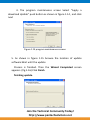
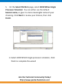
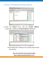
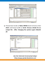
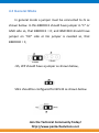
DSP/DSC BOARDS Software User Manual for BF532 Audio Development Boards Contents 1. Installation and Update VisualDSP++ .................................................................... 3 1.1 Install VisualDSP++ Software.............................................................................. 3 1.2 Install License and Register VisualDSP++ ............................................................ 7 1.3 Update VisualDSP++......................................................................................... 11 2. INSTALLATION and SESSION STARTUP ................................................................ 13 2.1 Start VisualDSP++ ............................................................................................. 14 3. Creating A Project In Visual Dsp .......................................................................... 19 3.1 Step 1: Start VisualDSP++ and Open a Project ................................................. 19 3.2 How To Create a New Project .......................................................................... 24 3.3 How To Changing the Project Options.............................................................. 28 4. Programming Flash Using Pantech Programming Software ................................ 31 4.1 Booting modes of BLACKFIN for Audio development board ............................. 31 4.2 Programming Mode ......................................................................................... 35 4.3 General Mode .................................................................................................. 37 4.4 Basic setup ....................................................................................................... 38 4.5 Programming uses Blackfin532 external flash programmer software ............. 39 5. Practical Dsp Applications: Audio Coding And Audio Effects ............................... 47 5.1 HANDS-ON EXPERIMENT -Talk through for the BF-532 Audio development Board ..................................................................................................................... 48 5.2 HANDS-ON EXPERIMENT 1.2 – Noise added, compressed and decompressed Using rand (), mu_law commands.......................................................................... 53 5.3 HANDS-ON EXPERIMENT – Noise removal using band pass and high pass filter .............................................................................................................................. 55 5.4 HANDS-ON EXPERIMENT – Digitalized Surround Sound Effects ....................... 56 5.5 HANDS-ON EXPERIMENT – Audio effects on Blackfin processor ...................... 58 Join the Technical Community Today! http://www.pantechsolutions.net 1. Installation and Update VisualDSP++ 1.1 Install VisualDSP++ Software VisualDSP is an integrated development and debugging environment from Analog Devices. 1. Push the power button of the PC 2. Login as a user with administrator rights 3. Copy the setup files that as shown in figure 1.1 to the PC and double clicks over the icon, The Install Shield Wizard screen appears We can download this setup file from Analog Devices Website from the Address http://www.analog.com/en/embedded-processing-dsp/software-andreference-designs/content/visualdsp_software_test_drive/fca.html We have to register for 90-days test drive, and then we can download the setup file. During the registration They will ask us to give the email-address to which they will send the Test Drive License. Join the Technical Community Today! http://www.pantechsolutions.net Fig 1.1 Setup file Fig.1-2 the InstallShield Wizard screen 4. Click Next. The License Agreement screen appears. (Fig.1-3) Fig.1-3 the License agreement screen Join the Technical Community Today! http://www.pantechsolutions.net 5. Read the license agreement, then select “I accept the terms in the license Agreement” and click next. The Customer Information screen appears. (Fig.1-4) Fig.1-4 the Customer Information screen 6. Fill in the user information. Click Next. The install path appears. (fig1.5) Fig.1-5 the install path screen Join the Technical Community Today! http://www.pantechsolutions.net 7. Click Next. The Install screen appears. (Fig.1-6) Fig.1-6 the Install screen 8. Click Install and wait until the install process is done. The Setup completed Successfully message box and Installation Completed screen appears.(fig.1-8) Click Finish to finish install. Join the Technical Community Today! http://www.pantechsolutions.net Fig.1-7 Setup completed successfully message box Fig.1-8 the Installation Completed screen 1.2 Install License and Register VisualDSP++ You must register your VisualDSP++ installation on-line to get a validation code. The Validation code is used to create the permanent license. Join the Technical Community Today! http://www.pantechsolutions.net 1. From the Start menu, choose Start->Programs (All Programs) ->Analog Devices> VisualDSP++ 5.0 >VisualDSP++ Environment. 2. An information screen asks if you would like to install a license. Click Yes. (Fig.1-7) Fig.1-9 information screen 3. The about VisualDSP++ dialog appears. (fig.1-9) Select Licenses and click New. Fig.1-9 about VisualDSP++ Licenses Join the Technical Community Today! http://www.pantechsolutions.net 4. Install New License screen appears. (fig.1-10) Select Node – locked license or Test Drive license and fill in the tools Serial number in the field exactly as it appears on your CD sleeve. Click Next. Fig.1-10 Install New License screen 5. An information window notifies of successful license installation.(fig.1-11) Click OK. Fig.1-11 License installs successful notice Join the Technical Community Today! http://www.pantechsolutions.net 6. Select the serial number (KIT-###-###-######-##) and click Validate. (Fig.1-11) Fig.1-11 about VisualDSP++ Licenses 7. Enter Validation Code dialog appears. (fig.1-12) Enter your validation code in the field And click OK. An information window notifies you of a successful validation. Click OK. (Fig.1-12). Validation Code screen. Join the Technical Community Today! http://www.pantechsolutions.net 1.3 Update VisualDSP++ 1. Visit Analog Devices Tools website at http://www.analog.com/en/embedded-processingdsp/software-and-referencedesigns/content/visualdsp_tools_upgrades/fca.html to get the latest software updates and patches. 2. Download "VisualDSP++ Release 5.0 - Update 4 September 2008 Update" or latest one. 3. From the Start menu, choose Start->Programs (All Programs) ->Analog DevicesVisualDSP++ 5.0 >maintain this installation. Note the figure 1.13 Figure 1.13 maintain this installation screen Join the Technical Community Today! http://www.pantechsolutions.net 4. The program maintenance screen Select “Apply a download Update” push button as shown in figure 1.14 , and click next Figure 1.14 program maintenances screen 5. As shown in figure 1.15 browse the location of update software Wait until the update Process is finished. Then the Wizard Completed screen appears. (fig.1-16) Click Finish finishing update. Join the Technical Community Today! http://www.pantechsolutions.net Figure 1.15 downloaded Updates Screen Figure.1-16 Wizard Completed 2. INSTALLATION and SESSION STARTUP 1. Plug the provided power supply into the Evaluation board. Visually verify that the green Power LED (D1) is on. 2. Connect one end of the UART cable to an available COM port on your PC and the Other End to the DB9 Connector Join the Technical Community Today! http://www.pantechsolutions.net 2.1 Start VisualDSP++ To start VisualDSP++ and creating a session following these steps, 1. Click the Windows Start button and select Programs, Analog Devices, VisualDSP++5.0, and VisualDSP++ Environment. If you are running VisualDSP++ for the first time, you will not be connected to a debug target. In VisualDSP++ 4.5, it is possible to edit and build your code without being connection to a debug target through a debug session. When you are ready to run and debug your program, you can quickly connect to a target and disconnect when you are finished. Doing so eliminates the overhead associated with the target connection, resulting in a smoother and more responsive experience. Join the Technical Community Today! http://www.pantechsolutions.net 2. When you need to connect to a debug session, click the Connect to Target toolbar button or choose from the available sessions listed under Select Session in the Session menu. To create a debug session, select New Session from the Session menu. This will launch the Session Wizard as shown below Join the Technical Community Today! http://www.pantechsolutions.net 3. On the Select Processor page, select the ADSP-BF532 processor from the Blackfin family. Click next to continue. 4. On the Select Connection Type page, select Simulator, and click Next to continue. Join the Technical Community Today! http://www.pantechsolutions.net 5. On the Select Platform page, select ADSP-BF5xx Single Processor Simulator. You can either use the default Session name, or give it a more meaningful name of your choosing. Click Next to review your choices, then click Finish 6. Select ADSP BF532 Single processor simulator, Click finish to complete the wizard Join the Technical Community Today! http://www.pantechsolutions.net 7. Go to select session from session menu and select the session created Join the Technical Community Today! http://www.pantechsolutions.net 3. Creating A Project In Visual Dsp 3.1 Step 1: Start VisualDSP++ and Open a Project To start VisualDSP++ and open a project Click the Windows Start button and select Programs, Analog Devices, VisualDSP++5.0, and VisualDSP++ Environment. If you are running VisualDSP++ for the first time, you will not be connected to a debug target. In VisualDSP++ 5.0, it is possible to edit and build your code without being connection to a debug target through a debug session. When you are ready to run and debug your program, you can quickly connect to a target and disconnect when you are finished. Doing so eliminates the overhead associated with the target connection, resulting in a smoother and more responsive experience. When you need to connect to a debug session, click the Connect to Target toolbar button or choose from the available sessions listed under Select Session in the Session menu. To create a debug session, select New Session from the Session menu. This will launch the Session Wizard, which is covered in previous chapter. If you have already run VisualDSP++ and the Reload last project at start up option is selected on the Project page under Settings Join the Technical Community Today! http://www.pantechsolutions.net and Preferences, VisualDSP++ opens the last project that you worked on. To close this project, choose Close and then Project from the File menu, and then click No when prompted to save the project. From the File menu, choose New and then Project to open the Project Wizard, shown below Join the Technical Community Today! http://www.pantechsolutions.net In the Name field, type any name .Click the browse button to the right of the Directory field to open the Browse For Folder dialog box. Click Next to bring up the Output Type page. Join the Technical Community Today! http://www.pantechsolutions.net Verify that the Processor type is ADSP-BF532, the Silicon Revision is Automatic, click next The Project output type is Executable file. Click Next to display the Add Start up Code/LDF page. Join the Technical Community Today! http://www.pantechsolutions.net Read the displayed text, and scroll down to the bottom of the page. Select the Don’t Add an LDF and start-up code option. When this project is created, start-up code that initializes and configures the processor will be added to the project, as will a Linker Description File that defines the target memory map and the placement of program sections within processor memory. The options available to configure the start-up code and LDF are beyond the scope of this tutorial. Make sure the Don’t Add an LDF and start-up code option is selected, and click Finish. The new project is created and is shown in the Project window of the IDDE. Click finish to complete the wizard Join the Technical Community Today! http://www.pantechsolutions.net 3.2 How To Create a New Project To add the source files to the new project: 1. Click the Add File button , or from the Project menu, choose Add to Project, and then choose File(s). Join the Technical Community Today! http://www.pantechsolutions.net 2. The Add Files dialog box appears .In the Look in box, locate the project folder, In the Files of type box, select All Source Files from the drop-down list. Select the file and Then click Add. 3. To display the files that you added in step 4, open the Source Files folder in the Project window. Click the Rebuild All button ( ) to build the project. The C source file opens in an editor window, and execution halts Save the Project and then builds the Project. . Join the Technical Community Today! http://www.pantechsolutions.net 4. Build the project by performing one of these actions. • Click the Build Project button or From the Project menu, choose Build Project. At the end compilation, the Output window displays this message in the Build view: Join the Technical Community Today! http://www.pantechsolutions.net “Build completed successfully.” The project can be rebuild by choosing rebuild all. Press F5 to run the project Join the Technical Community Today! http://www.pantechsolutions.net 3.3 How To Changing the Project Options From the Project menu click the Project Options command to display the Project Options dialog box This dialog box enables you to specify project build information. Join the Technical Community Today! http://www.pantechsolutions.net Take a moment to view the various pages in the Project Options dialog box by selecting them from the tree on the left: Project, General, Compile, Assemble, Link, Load, Pre-Build, and Post-Build. On each page, you specify the tool options used to build the project. On the Project page , verify that the values shown in Table are entered here. Field Value Processor ADSP BF532 Revision Automatic Type Loader File Name File.c Settings Configuration For Debug These settings specify information for building an executable file for the ADSP-BF533 processor. The executable contains debug information, so you can examine program execution. Click the LOAD tab to display the General page, shown in Figure Join the Technical Community Today! http://www.pantechsolutions.net Choose boot mode as flash/ PROM, Boot Format as Intel ASCII and Output width as 16 bit. Choose a folder for an output file . After changing the options again Rebuild All Join the Technical Community Today! http://www.pantechsolutions.net Loader file will be generated in the folder mentioned in the project options This loader can be loaded in the flash memory by using Blackfin external flash programmer which is explained in chapter 4 4. Programming Flash Using Pantech Programming Software 4.1 Booting modes of BLACKFIN for Audio development board The ADSP-BF531/ADSP-BF532/ADSP-BF533 processor has two mechanisms (listed in Table ) for automatically loading internal L1 instruction memory after a reset. A third mode is provided to execute from external memory, bypassing the boot sequence. Join the Technical Community Today! http://www.pantechsolutions.net Jumper settings J5-BMODE1 J6-BMODE0 Boot Mode 00 01 10 11 Description Execute from 16 bit external memory (Bypass Boot Rom) Boot from 8bit/16 bit flash Boot from serial master Boot from serial slave EEPROM/flash(8/16or 24 bit address range ) Notes: 1. Here in these diagrams “C” side is GND side. So, if we connect a jumper in “C” side the Corresponding pin is “0” 2. The BMODE pins have Pull-ups in the Circuit. So, to make any BMODE to “HIGH“there is no need to connect Join the Technical Community Today! http://www.pantechsolutions.net Anything. The “NC” Side is No Connection Side The BMODE pins of the reset configuration register (SYSCFG), sampled during power-on resets and softwareinitiated resets, implement the following modes: Execute from 16-bit external memory – Execution starts from address 0x2000 0000 with 16-bit packing. The boot ROM is bypassed in this mode. All configuration settings are set for the slowest device possible (3-cycle hold time; 15-cycle R/W access times; 4-cycle setup). Boot from 8-bit or 16-bit external flash memory – The flash boot routine located in boot ROM memory space is set up using asynchronous Memory Bank 0. All configuration settings are set for the slowest device possible (3-cycle hold time; 15-cycle R/W access times; 4cycle setup). Boot from SPI serial EEPROM/flash (8-, 16-, or 24-bit addressable, or Atmel AT45DB041, AT45DB081, or AT45DB161) – The SPI uses the PF2 output pin to select a single SPI EEPROM/flash device, submits a read command Join the Technical Community Today! http://www.pantechsolutions.net and successive address bytes (0x00) until a valid 8-, 16-, or 24-bit addressable EEPROM/flash device is detected, and begins clocking data into the processor at the beginning of L1 instruction memory. Boot from SPI serial master – The Blackfin processor operates in SPI slave mode and is configured to receive the bytes of the LDR file from an SPI host (master) agent. To hold off the host device from transmitting while the boot ROM is busy, the Blackfin processor asserts a GPIO pin, called host wait (HWAIT), to signal the host device not to send any more bytes until the flag is deasserted. The GPIO pin is chosen by the user and this information is transferred to the Blackfin processor via bits[10:5] of the FLAG header in the LDR image. For each of the boot modes, a 10-byte header is first read from an external memory device. The header specifies the number of bytes to be transferred and the memory destination address. Multiple memory blocks may be loaded by any boot sequence. Once all blocks are loaded, program execution commences from the start of L1 Join the Technical Community Today! http://www.pantechsolutions.net instruction SRAM. In addition, Bit 4 of the reset configuration register can be set by application code to bypass the normal boot sequence during a software reset. For this case, the processor jumps directly to the beginning of L1 instruction memory. Every Board comes along with SPI Boot loader, ensure there is jumper on WP and Jumper in J8 We have two modes Programming Mode(Booting from SPI –BOOTMODE:11) General or Normal Mode(Booting 8-/16-bit Flash— BOOTMODE:-01) 4.2 Programming Mode Join the Technical Community Today! http://www.pantechsolutions.net In Programming Mode J5, J6 (BMODE1,BMODE0)should be connected on connection side(NC) as shown below . So, that processor BOOTMODE is 11. .This mode will boot the processor from SPI. J15, WP should have a jumper as shown below, SSEL should be configured for BF532 as shown below Join the Technical Community Today! http://www.pantechsolutions.net 4.3 General Mode In general mode a jumper must be connected to J5 as shown below. In this BMODE1 should have jumper in “C” or GND side so, that BMODE1 = 0; and BMODE0 should have jumper on “NC” side or No jumper is needed so, that BMODE0 = 1; J15, WP should have a jumper as shown below, SSEL should be configured for BF532 as shown below Join the Technical Community Today! http://www.pantechsolutions.net And Reset the kit Previously whatever are there in the ”Programming Mode” keep all, Additionally just we need to put the JUMPER in J1 or BMODE1 in “C” side Now the Boot Mode is changed to “01 ” where it will Boot from 8bit/16-bit Flash 4.4 Basic setup Blackfin External Flash programmer is Windows software from the Pantech solutions private limited that allows easy access to the Flash memory. These features include: •Communicating to the Black fin development module • Erasing the Flash memory • Programming the Flash memory Join the Technical Community Today! http://www.pantechsolutions.net audio External flash programmer provides a clear and simple user interface to these features and more as described in the following sections. Minimum Requirements • Windows 95/98/ME/NT/2000/XP • Mouse • COM Port • 16Mb RAM • 3Mb Disk Space 4.5 Programming uses Blackfin532 external flash programmer software Main Window The following is a screenshot of the main window. Join the Technical Community Today! http://www.pantechsolutions.net The window is divided up into six sections. Work your way from section 1 to section 4 to program a device using the most common functions. Each section is described in detail in the following sections. At the very bottom the window is an area where output messages will be displayed and at the very bottom right is where the progress bar is displayed. Four Step Programming For each step there is a corresponding section in the main window as described in the User Interface Tour. Join the Technical Community Today! http://www.pantechsolutions.net Step 1 – Connection Settings Before the device can be used the settings required to make a connection must be specified. Select the desired COM port from the drop down list or type the desired COM port directly into the box. If you enter the COM port yourself then you must enter it in one of the following formats Port name COM1 Baud Rate 9600 Stop bits 1 Data bits 8 Join the Technical Community Today! http://www.pantechsolutions.net Port connected successfully will be displayed in output window If the port is not connected .The following message will display. Join the Technical Community Today! http://www.pantechsolutions.net Ensure the kit is in programming mode and Press the RESET button in the Kit and try again. Step 2 – Erasing Press the erase button Click ok to continue after erasing the following message will be displayed in output window Join the Technical Community Today! http://www.pantechsolutions.net Step 3 – Selecting the Hex File Select the file by using browse button. The status bar will show you the memory occupied and the file contents, file size and checksum will be displayed in status window. Join the Technical Community Today! http://www.pantechsolutions.net Step 4 – Programming the flash Click program button to program the device Join the Technical Community Today! http://www.pantechsolutions.net After programming kit should be connected in general mode and reset the kit again About Us This box provide the information about product description, Version, Copy right and company name Help Join the Technical Community Today! http://www.pantechsolutions.net 5. Practical Dsp Applications: Audio Coding And Audio Effects Audio coding exploits unique features of audio signals to compress audio data for storage or transmission. Today, digital audio coding techniques are widely used in consumer electronics such as portable audio players. This chapter introduces basic audio effects and their implementations are presented and used for experiments. Join the Technical Community Today! http://www.pantechsolutions.net 5.1 HANDS-ON EXPERIMENT -Talk through for the BF-532 Audio development Board This experiment implements a real-time Talkthrough with the BF532 Audio development board. A stereo or mono sound source is connected to the audio input channels of the BF532 Audio development board, and the output of the development board is connected to a headphone or speaker. The project files are located in directory --------\final\Talkthrough, Load the project file, (Open the project option menu and select Processor – ADSP-BF532 and Type – loader file) ,and finally build and run the project. The loader (Hex) file will be created. Programming Mode In Programming Mode we should not connect any jumper to J5 and J6. The JUMPERS should be there in J13, J12, and J16 Such as MOSI, WP and SSEL Should be Configured for BF532 i.e. The JUMPER should be there in Join the Technical Community Today! http://www.pantechsolutions.net the BF532 Side. Now Actually BF532 Booting in “11“mode i.e. booting From SPI Flash for boot modes refers BF532 Hardware reference manual Step 1 – Connection Settings Before the device can be used the settings required to make a connection must be specified Select the desired COM port from the drop down list or type the desired COM port directly into the box. If you enter the COM port yourself then you must enter it in one of the following formats Port name COM1 Baud Rate 9600 Stop bits 1 Data bits 8 Join the Technical Community Today! http://www.pantechsolutions.net Port connected successfully will be displayed in output window If it the port is not connected .The following message will display… Ensure the kit is in proper mode and Press the RESET button in the Kit and try again.. Join the Technical Community Today! http://www.pantechsolutions.net Step 2 – Erasing Press the erase button Click ok to continue after erasing the following message will be displayed in output window Join the Technical Community Today! http://www.pantechsolutions.net Step 3 – Selecting the Hex File Select the file by using browse button. The progress bar will show you the memory occupied and the file contents, file size and checksum will be displayed in status window. Step 4 – Programming the flash Click program to program the device Join the Technical Community Today! http://www.pantechsolutions.net 2. General Mode: In general mode a jumper must be connected to J1 as shown below. Previously whatever are there in the “Programming Mode” keep all Additionally just we need to put the JUMPER in J5 or BMODE1 in “C” side ,reset the board one times .Now the Boot Mode is changed to “01 ” where it will Boot from 8-bit/16-bit Flash. 5.2 HANDS-ON EXPERIMENT 1.2 – Noise added, compressed and decompressed Using rand (), mu_law commands Join the Technical Community Today! http://www.pantechsolutions.net This experiment implements add noise to the signal with the Blackfin processor.. The project files are located in directory ---\final\noise, Load the project file, (Open the project option menu and select Processor –ADSP-BF532 and Type – loader file) ,and finally build and run the project. The loader file will be created. To accomplish this EXPERIMENT, A sound is inputted to a development board. A random uniform white noise function is generated and added to the sound data. This data is compressed using mu-law compression and then decompresses the data and processes it. If the first button (SW3) is pressed, the Original sound is played. If the second button (SW1) is pressed, the sound is played with noise. Programming Mode, Programming the flash , Connection Settings, and General Mode same as HANDS-ON EXPERIMENT 5.1 Join the Technical Community Today! http://www.pantechsolutions.net 5.3 HANDS-ON EXPERIMENT – Noise removal using band pass and high pass filter This experiment implements noise removal from the signal with the Blackfin processor.. The project files are located in directory ------\final\NOISEREMOVAL , Load the project file, (Open the project option menu and select Processor – ADSP-BF532 and Type – loader file) ,and finally build and run the project. The loader file will be created. To accomplish this Project, A sound is inputted to a development board. A random uniform white noise function is generated and added to the sound data. This data is compressed using mu-law compression and then decompresses the data and band pass and high pass filter processes for noise removal. If the first button (SW3) is pressed, the Original sound is played. If the second button (SW1) is pressed first time, the sound is played with removal of noise from band pass filter. Join the Technical Community Today! http://www.pantechsolutions.net If the second button (SW1) is pressed Second time, the sound is played with removal of noise from High pass filter. Programming Mode, Programming the flash, Connection Settings, and General Mode same as HANDS-ON EXPERIMENT 5.1 5.4 HANDS-ON EXPERIMENT – Digitalized Surround Sound Effects This experiment implements Digitalized Surround Sound Effects with the Blackfin processor.. The project files are located in directory ----\final\ Digitaleffect532,Load the project file, (Open the project option menu and select Processor –ADSP-BF532 and Type – loader file) ,and finally build and run the project. The loader file will be created. The objective of the EXPERIMENT was to create surround sound effects (this project considers surround sound as movement of sound between different speakers) such that the user can feel the sound moving across the users head. Join the Technical Community Today! http://www.pantechsolutions.net Ideally this effect should have an input sound signal processed such that the sound from an input source moves around the user’s head at a revolution rate of few milliseconds. To study the acoustic effects this EXPERIMENT considered different revolution rates to determine the most optimal values and effects different revolution rates can have on users hearing. If the first button (SW3) is pressed, the Original sound is played. If the second button (SW1) is pressed first time, the sound is played with Surround Sound Effects. Code description: This case populates a huge buffer to store 14400 samples of input dma buffer. The length of this buffer is predetermined so that it holds values for all four speakers pointers are pointing to equal delta time delay of 0.1 seconds. First the buffer is populated at least for once. Join the Technical Community Today! http://www.pantechsolutions.net Then the values pointed by all four speaker pointers are written to the output dma buffer for each of the speakers. Thereafter, the speaker pointers point to the next item on the buffer. Programming Mode, Programming the flash, Connection Settings, and General Mode same as HANDS-ON EXPERIMENT 5.1 5.5 HANDS-ON EXPERIMENT – Audio effects on Blackfin processor This experiment implements Audio effects on Blackfin processor with the Blackfin processor.. The project files are located in directory ----\final\chrous, Load the project file, (Open the project option menu and select Processor – ADSP-BF532 and Type – loader file) ,and finally build and run the project. The loader file will be created. If the first button (SW3) is pressed, the Original sound is played. If the second button (SW1) is pressed first time, the sound is played with Chorus Sound Effects. Join the Technical Community Today! http://www.pantechsolutions.net Chorus: This effect is used to thicken the output signal by adding to it a delayed signal. The effect would give the sound like there is more than one instrument playing at the same time. Join the Technical Community Today! http://www.pantechsolutions.net Did you enjoy the read? Pantech solutions creates information packed technical documents like this one every month. And our website is a rich and trusted resource used by a vibrant online community of more than 1,00,000 members from organization of all shapes and sizes. Join the Technical Community Today! http://www.pantechsolutions.net What do we sell? Our products range from Various Microcontroller development boards, DSP Boards, FPGA/CPLD boards, Communication Kits, Power electronics, Basic electronics, Robotics, Sensors, Electronic components and much more . Our goal is to make finding the parts and information you need easier and affordable so you can create awesome projects and training from Basic to Cutting edge technology. Join the Technical Community Today! http://www.pantechsolutions.net