1
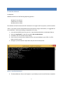
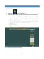
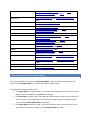
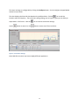
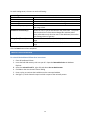
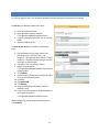
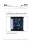
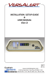
Energy Monitoring Dashboard User Manual International Headquarters B+B SmartWorx. 707 Dayton Road Ottawa, IL 61350 USA Phone (815) 433-5100 -- General Fax (815) 433-5105 Website: www.bb-smartworx.com [email protected] European Headquarters B+B SmartWorx Westlink Commercial Park Oranmore, Co. Galway, Ireland Phone +353 91-792444 -- Fax +353 91-792445 Document: APP-BNRG_Wzzard_Energy_Monitoring_Dashboard_R1_4615m 2 CONTENTS OF PACKAGE The package includes: B+B SmartWorx USB Flash Drive Quick Start Guide SOFTWARE B+B’s Wzzard Energy Monitoring Platform featuring: • Support for 1-32 nodes with 1-3 sensors per node • Real time data display, selectable between Amps, KW, dollar cost • Historical function • User programmable high/low limits for email/SMS alerts • Ability to export data 3 ABOUT THE ENERGY MONITORING DASHBOARD The Wzzard™ Energy Monitoring Application makes it simple to see the real time and historical electrical consumption of any individual machine or panel. Data can be exported for further analysis. Email or text message alerts can be sent when user-configured high or low limits are exceeded in critical applications. Installation costs are kept low using the Wzzard wireless sensing platform. The platform creates a selfforming, self -healing wireless mesh network that eliminates the need for wires and requires no special skills to install. Each Wzzard sensor node is powered by long life batteries. Install the monitoring software on your Windows PC. You can monitor the energy dashboard on that machine, or configure it to serve web pages that you can monitor from any web browser on your network. 4 DASHBOARD INSTALLATION To install the dashboard: Pre Requisite: Windows PC with one of the following Operating Systems: Windows 7 32 or 64-bit * windows 8.1 32 or 64-bit Windows 10 32 or 64-bit The software will look for Microsoft .NET Framework 4.5 or higher and if not present, it will be installed. *Note: If you want to access the dashboard from other devices using a web browser, it is suggested not to use Windows 7. Before proceeding, see Appendix A for setup 1. 2. 3. 4. Insert the B+B USB flash drive into your PC. Open the Removable drive via Windows Explorer. Select the install.cmd file, right click and select Run as administrator. Click Yes on the User Account Control Dialog Press any key to continue the installation on the command window or press CTRL-C or CTRLBreak to exit the install. 5. See Figure 1, which shows the steps which are part of the install process. Figure 1: Install B+B Dashboard 6. The Wzzard Monitor Short cut will appear on your desktop once the install has been completed. 5 RUNNING DASHBOARD To run the Dashboard: 1. Double click the shortcut on your Desktop 2. The main page of the dashboard is displayed. The main page allows you to do the following: a. View the real-time reading/status of each assigned node analog sensor. b. Configure the Units being displayed, in Amps, kw, or $/hr by clicking the corresponding button. c. View Hidden Nodes d. View Unassigned Nodes e. Modify the System Configuration o If the gateway/broker IP address has changed from the default, this must be set on the System Configuration screen in order to see the nodes f. Manage Nodes g. Refresh the screen Figure 2: Main Page with assigned nodes and alerts 6 SYSTEM CONFIGURATION The System Configuration screen allows you to set the broker IP address, the kw/hour rate, and the email address and SMTP server settings for sending email alerts. Click the System Configuration Button on the Main screen Figure 3: System Configuration If your gateway was setup on a network or is not using the default IP Address of 192.168.1.1, then set the Broker IP Address and click the Activate button. Once it is done activating, click the Done button to return to the main page. Enter the kw/hour rate ($) that is being charged for your electrical service. This is used in the calculation when the $/hr units are being displayed on the main page. If you want to receive alert emails, set the following: Set Alert Email Address to the email that you would like the alert to go to. This could be an email or text address Set SMTP Username to your email address (e.g. [email protected]) 7 Set SMTP Password to your email password (e.g. 16-character password which was previously generated) Set SMTP Server to your email server (e.g. smtp.gmail.com) Click Activate SMTP Settings Press the Done button to return to the main page Note: It is recommended to set up a separate account for sending alerts. The document assumes that a Gmail SMTP account will be used. This account must enable 2 Step Verification and have an app password generated. To set up 2 Step Verification, follow these steps: 1. 2. 3. 4. Sign in to My Account. In the Sign-in & Security section, select Signing in to Google. Choose 2-Step Verification. This will bring you to the 2-Step Verification settings page. You will then see a step-by-step guide which will help you through the setup process. Next you will need to generate an app password. 1. 2. 3. 4. 5. Visit your App passwords page. You may be asked to sign in to your Google Account. At the bottom, click Select app and choose the app you’re using. Click Select device and choose the device you’re using. Select Generate. Follow the instructions to enter the App password (the 16 character code in the yellow bar) on your device. 6. Select Done. Once you are finished, you won’t see that App password code again. However, you will see a list of apps and devices you’ve created App passwords for. If you want to receive alerts via text message on your mobile device, you can set the Alert Email Address to a provider based address. Below is a list of the commonly used provider addresses. Check with your mobile service provider for updated addresses. 8 Alltel Wireless [email protected] (SMS & MMS) [email protected] (SMS) [email protected] (MMS) AT&T Wireless [email protected] (SMS) [email protected] (MMS) AT&T Mobility (formerly Cingular) [email protected] [email protected] Boost Mobile [email protected] Cricket [email protected] (SMS) [email protected] (MMS) Metro PCS [email protected] Sprint (PCS) [email protected] SMS) [email protected] (MMS) Sprint (Nextel) [email protected] (SMS) [email protected] (Rich Messaging) Straight Talk [email protected] (SMS) [email protected] (MMS) T-Mobile [email protected] (MMS) U.S. Cellular [email protected] (SMS) [email protected] (MMS) Verizon [email protected] (SMS) [email protected] (MMS) Virgin Mobile [email protected] (SMS) [email protected] (MMS) Esendex (AU,ES,FR,IE,UK) [email protected] MobileMail.RU [email protected] Table 1: Commonly used provider addresses CONFIGURE UNASSIGNED OR HIDDEN NODES All Unassigned Nodes are located in the Unassigned Nodes list box. All nodes on your network will appear in the Unassigned Node list. You can assign, hide or delete a node. To configure an Unassigned Node, click it. Click Assign Node to assign the node. Once a node is in the assigned state, the node will start to display its sensor readings on the Dashboards main page Click Hide Node to hide the node. You might hide a node because you don’t want to monitor it. Once the node is in the hidden state, the node no longer appears in the unassigned node list. You can click the Show Hidden Nodes to view them. Click Delete Node to delete the node. If you want to delete a node, its best to remove it from your network. *To remove a node from the Unassigned Node list, hide it. 9 All Hidden Nodes are located in the Hidden Nodes list box. You can assign or delete a node. To configure a Hidden Node, click it. Click Assign Node to assign the node. Once a node is in the assigned state, the node will start to display its sensor readings on the Dashboards main page. Click Delete Node to delete the node. If you want to delete a node, it is best to remove it from your network. *To remove a node from the Unassigned Node list, hide it. MANAGE NODES If you click the Manage Nodes button, it will allow the user to delete all nodes (unassigned, assigned, and hidden). There is also an option to delete one assigned node at a time. Once the assigned node is deleted, it will reappear in the unassigned nodes list if the node is still being reported by the broker. ASSIGNED NODE STATUS, TREND, AND CONFIGURATION To view an Assigned Node’s status and configuration, click an assigned node which is located in the table on the main screen. Figure 4 shows the current readings of the Analog Inputs, the Internal Temperature and the Supply Voltage. In the center of the screen it lists the BLE MAC address of the unit as well as the Node Description if it exists. The trend chart displays the data based on the published data. Figure 4: Node Status and Configuration 10 The sensor settings are configurable by clicking the Configure button. See the Configure Assigned Nodes section for more detail. The chart displays the historical data based on the published data. Click the icon to edit the Duration and Grid Frequency. The trend chart settings dialog, seen in Figure 5, gives you the ability to export data in .CSV format. Click the Use the button to zoom in or the icon to close the trend chart settings. button to zoom out of the trend chart. Figure 5: Trend Chart Settings Note: Web Client screens may have a slightly different appearance. 11 CONFIGURE ASSIGNED NODES The following describes the assigned node and input configuration settings. Figure 6: Configure Assigned Node Node Configuration Node Name/ Description Stale Period Trend Chart Y Axis Min and Max A text field which gives the user the ability to set a description of the node A visual alert will occur on the main page if the sensor hasn’t reported within the set time period Allows the user to modify the scale of the Y Axis on the trend chart 12 For each Analog sensor, the user can set the following: Input Configuration Input Enabled Sensor Label Normal Range Min Normal Range Max Alert Enabled (Min/Max) Yellow Alert Threshold (%) Voltage (for $/hr math) Power Factor Allows the user to enable or disable the sensor A text field which gives the user the ability to set a label for the input Allows the user to set the normal minimum range Allows the user to set the normal maximum range Enable or disable the visual and email alerts for the related min and max range values Allows the user to set the threshold for the yellow alert. The yellow alert threshold is x% of the Normal Range Min and Max values. Note yellow Alerts only alert the user via the dashboard, An email or text message does not get sent. This is used in the calculation for the displayed units on the main page This is used in the calculation for the displayed units on the main page Click the Done button when completed. UNINSTALLING DASHBOARD To uninstall the dashboard follow these instructions: 1. Close all Dashboard Clients 2. Insert the B+B USB memory stick into your PC. Open the Removable Drive via Windows Explorer. 3. Select the uninstall.cmd file, right click and select Run as administrator 4. Click Yes on the User Account Control Dialog 5. Press any key to continue the installation on the command window 6. See Figure 7, which shows the steps in which are part of the uninstall process. 13 Figure 7: Uninstall Dashboard 14 APPENDIX A: SET UP IIS WEB SERVER If you would like to run a web client, perform these steps: 1. Uninstall the Dashboard if you have already installed it. Follow the Uninstalled Dashboard Section. One must enable IIS prior to installing the dashboard. WARNING: Uninstalling the Dashboard will remove any historical data the system has stored. 2. Open Windows Control Panel 3. Click the “Programs and Features” icon 4. In the left had navigation pane, select “Turn Windows features on or off” 5. Expand the “Internet Information Services” feature and turn on the following circled features 6. Click OK 7. Follow the directions in the Dashboard Installation section to install the Dashboard. 8. To allow remote access to the web client, select the ‘Firewall_Setup.cmd’ file, right click and select ‘Run as administrator’ after the Dashboard installation is complete. The following Internet Browsers were tested and recommended: Chrome Version 43.0.x Mozilla Firefox Version 38.0.x Internet Explorer 11.0.x Use the following URL to access the Dashboard via a web client: From installed PC http://localhost/StatusEnterpriseGateway From a networked PC http://<IP address>/StatusEnterpriseGateway Note: Only one web client can be logged in at a time. 15 APPENDIX B: DATABASE MAINTENANCE To improve response times, the dashboard database should be periodically backed up and renewed. To back up your database, follow these steps: 1. Close all Dashboard Clients 2. Open Windows Explorer and go to C:\ProgramData\BScada\StatusEnterprise 3. Copy the ‘StatusEnterprise.db3’ file to a Backup folder 4. Append a .bak to this file To clean up and renew your database, follow these steps: 5. Run the Database Utility App, found in the following location of the PC: Start -> All Programs -> B-Scada Enterprise Edition -> Status Enterprise -> Database Utility and right click and select Run as administrator. 6. Click Yes on the User Account Control 7. Browse to the database C:\ProgramData\BScada\StatusEnterprise\Status Enterprise.db3 8. Click Connect 9. Set Destination File Browse to the Backup folder and type StatusEnterprise.db3 10. Click Save 11. Click Renew DB 12. Click Backup 13. Once the backup has completed, close the Database Utility 14. Copy the new file located in the Backup folder to the original file location C:\ProgramData\BScada\StatusEnterprise When prompted to provide administrator permission, click Continue 16 B&B SMARTWORX TECHNICAL SUPPORT Phone: 1-800-346-3119 (Monday - Friday, 7 a.m. to 5:30 p.m. CST) Fax: 815-433-5109 Email: [email protected] Web: www-bb-smartworx.com 17