1
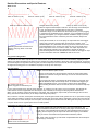
holds steady for a fraction of a second, the auto-reset is re-enabled and it
will snap back in sync at the next Ping or Reset Lock Point.
Delving further into the nitty-gritty of timing, you can override this feature.
Let's say your patch requires resyncing 100% of the time, on every beat
without compromises, and at the same time you want to modulate skew all
over the place. Just mult/stack your ping clock into the Reset jack (or send
some other clock into Reset if you want phase shift). A pulse received on
the Reset jack will force a reset to occur, even if Skew is being modulated.
Bottom: Ping (for reference). Top is output while Again, this "just does what you think it will do", but if you've made it this far
skew is being modulated continually, starting
in the manual, you deserve to know what's really going on!
with the second triangle wave. Notice how
period and phase are variable.
Jumpers and Trimpots
Bipolar/Unipolar jumper
This jumper selects "Bipolar" output (-5V to +5V waveforms), or "Unipolar" output (0V to
+10V). On PCB version 1.0, the jumper is labeled "BIPOLAR" on the left side. Putting
the jumper between the left pin and center pin gives you Bipolar mode (-5V to +5V).
Putting the jumper between the right pin and center pin is Unipolar mode (0V to 10V).
On PCB v1.0.1, the jumper is labeled +/-5V and 0/+10V.
Factory default is Unipolar mode.
Fire-on-unmute jumpers
Each channel has a jumper to enable "Fire-on-unmute" mode. These jumpers are
located in between the two PCBs, above the buttons. Installing the jumper enables the
Fire-on-unmute mode for that channel.
In this mode, turning the On button from off to on will fire a quick pulse into the Reset
jack. This will reset the waveform. This is useful for using the QPLFO as a one-shot, or
for manually re-syncing the LFO.
Each channel has its own jumper, so you could enable this on all, none, or only some of
the channels.
Factory default is no jumpers (all off).
Threshold Trimpot Adjustment
The trimpot on the back of the QPLFO adjusts the voltage required to trigger a ping or reset.
At fully CCW, the voltage is 5.0V. At center, it's 2.5V. At fully CW it's 0V and the unit will not
respond to Ping or Reset.
The QPLFO can be interfaced with LZX-level compatible equipement by setting this trimpot to
about 0.8V.
It's safe to turn the trimpot with the unit powered up, but normal cautions apply when handling
any piece of equipment that's "live". You can use a volt meter to measure the voltage on the
wiper of the trimpot as you turn it. This voltage will be the threshold voltage.
Factory default is about 2V, or roughly near half-way.
Headers
Reserved for future use.
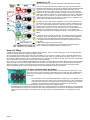
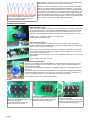
In the initial release firmware, jumping
LFO outputs: connects to 4ms VCA
Matrix Input, Toppobrillo Mixiplexer (with pins makes each channel free-running
(disables auto-stop of Ping clock).
adaptor), or 4ms SISM.
In the photo, the bottom row is the
signals, the top row is ground
Page 8
Ping jack normalizations.
Connects to 4ms QCD.
In the photo, the top row is ground, and
the each pin on the bottom row connects
to the normalization of a Ping jack.