1
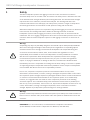
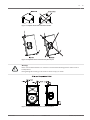
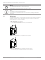
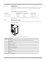
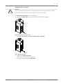
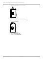
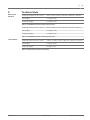
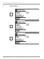
EKX Full-Range Loudspeaker Accessories
EKX-BRKT12, EKX-BRKT15, and EKX-TCA
en | Installation Note
en
3
Table of contents
1
Safety
4
1.1
Safety point
6
2
Installation
7
2.1
Wall mount bracket
2.2
Truss adapter
12
3
Technical data
17
4
Product labels
18
5
Notes
19
Electro-Voice
7
Installation Note
2015.03 | 01 | F.01U.308.107
EKX Full-Range Loudspeaker Accessories
Safety
1
The EKX loudspeaker systems and rigging accessories in this manual have a minimum
structural safety factor of 8:1 when used as intended. The safety factor is defined as the ratio
of the ultimate-break strength divided by the working-load limit. The ultimate-break strength
represents the force at which a part will structurally fail. The working-load limit is the
maximum load that the user shall apply. The safety factor provides a margin of safety above
the working-load limit to accommodate normal dynamic loading and normal wear.
When EKX loudspeaker systems are suspended using the EKX rigging accessories as illustrated
in this manual, the resulting loads will be within the working-load limits of both the
loudspeaker systems and the rigging accessories, and a safety factor of at least 8:1 will be
maintained. The use of rigging configurations other than recommended by Electro-Voice in this
manual for either the EKX loudspeaker systems or EKX rigging accessories are at the risk of
the user.
Warning!
Suspending any object is potentially dangerous and should only be attempted by individuals
who have a thorough knowledge of the techniques and regulations of suspending objects
overhead. Electro-Voice strongly recommends all loudspeakers be suspended taking into
account all current national, federal, state, and local laws and regulations. It is the
!
responsibility of the installer to ensure all loudspeakers are safely installed in accordance
with all such requirements. When loudspeakers are suspended, Electro-Voice strongly
recommends the system be inspected at least once per year or as laws and regulations
require. If any sign of weakness or damage is detected, remedial action should be taken
immediately. The user is responsible for making sure the wall, ceiling, or structure is capable
of supporting all objects suspended overhead. Any hardware used to suspend a loudspeaker
not associated with Electro-Voice is the responsibility of others.
Prior to use, inspect the suspension points and associated hardware for any cracks,
deformations, broken welds, corrosion, missing or damaged components which could reduce
the suspension points strength. Replace any damaged hardware. Never exceed the limitations
or maximum recommended load intended for the suspension points. As an added safety
measure, it is suggested the user install an extra suspension point back to the building
structural supports. This redundant safety point should have as little slack as possible (less
than one (1) inch is preferable). Prior to each use, inspect the loudspeaker enclosures for any
cracks, deformations, missing or damaged components, which could reduce enclosure
strength. Replace any loudspeaker systems damaged or missing hardware.
Warning!
!
Eyebolts must be fully seated and oriented in the plane of pull. Always use fender washers at
least 1.5 inch in diameter and 1/16 inch thick under the eyebolt to distribute the load on the
enclosure.
REFERENCE: For more information, see EKX Powered Loudspeaker User Manual
(F.01U.308.095) or EKX Passive Loudspeaker User Manual (F.01U.308.100).
2015.03 | 01 | F.01U.308.107
Installation Note
Electro-Voice
en
5
Figure 1.1: Eyebolt shown with and without washer
Figure 1.2: Eyebolts shown oriented in the plane of pull
Warning!
!
Never exceed the limitations or maximum recommended working load for Electro-Voice
loudspeakers.
Disregarding this warning could result in serious injury or death.
Figure 1.3: Maximum working load - vertical orientation
Electro-Voice
Installation Note
2015.03 | 01 | F.01U.308.107
EKX Full-Range Loudspeaker Accessories
Warning!
!
Never suspend EKX loudspeaker in a vertical column array.
Disregarding this warning could result in serious injury or death.
Notice!
If the eyebolts are removed reinstall the screws.
If the screws are not reinstalled air leaks occur in the enclosure, resulting in undesirable
performance.
1.1
Safety point
As an added safety measure, it is suggested the user install an extra suspension point back to
the building structural supports. This redundant safety point should have as little slack as
possible (less than one (1) inch is preferable).
To add a safety point, do the following:
1.
Remove one (1) of the screws from the top of the loudspeaker.
2.
Replace the screw with one (1) eyebolt and one (1) washer.
3.
Tether the safety point back to the building structural supports.
An added safety point is established back to the structural supports.
2015.03 | 01 | F.01U.308.107
Installation Note
Electro-Voice
en
7
Installation
2
Thank you for choosing an EKX loudspeaker accessory. This installation guide describes how
to install the wall mount brackets and truss adapter used with EKX full-range loudspeaker
systems.
EKX Full-Range Loudspeaker Accessory Guide
Loudspeaker
Wall Mount Bracket
Truss Adapter
M10 Eyebolt Kit
EKX-12 and EKX-12P
EKX-BRKT12
ETX-TCA
EBK-M10-3PACK
EKX-15 and EKX-15P
EKX-BRKT15
ETX-TCA
EBK-M10-3PACK
For more information, see EBK-M10 Eyebolt Attachment Kit Installation Instructions
(F.01U.303.870).
Wall mount bracket
2.1
The wall mount bracket is used to mount an EKX-12, EKX-15, EKX-12P, or EKX-15P full-range
loudspeaker to the wall.
The wall mount bracket kit contains the following:
Quantity:
Description:
1
EKX Full-Range Loudspeaker Accessories Installation Note (F.01U.308.107)
1
Allen Wrench
4
M10 Split Lock Washers
4
M10 Flat Washers
4
M10 Button Head Screws
2
M8 Socket Head Cap Screws
1
T-Bracket
1
T-Bracket with hook
1
U-Bracket
Table 2.1: Wall mount kit components
Electro-Voice
Installation Note
2015.03 | 01 | F.01U.308.107
EKX Full-Range Loudspeaker Accessories
Attaching the T-Brackets
Use the correct size wall mount bracket kit designed for your EKX-12, EKX-15, EKX-12P or
EKX-15P full-range loudspeaker. The EKX-15 loudspeaker is shown in the illustrations. For
more information, see EKX Full-Range Loudspeaker Accessory Guide, page 7.
To attach the T-Brackets to EKX-12, EKX-15, EKX-12P, or EKX-15P loudspeaker, do the
following:
1.
Using an Allen wrench (supplied), remove the four (4) rear suspension point M10 screws
from the loudspeaker.
Figure 2.1: Removing screws
2.
Align the T-Bracket with the holes on the top and rear of the loudspeaker (Vertical).
OR
Align the T-Bracket with the holes on the right and rear of the loudspeaker (Horizontal).
Notice!
When mounting a loudspeaker horizontally, the T-Bracket with hook needs to be installed on
the left side as you face the front of the loudspeaker.
Figure 2.2: T-Brackets Vertical (left) Horizontal (right)
3.
Insert two (2) of the M10 button head screws, two (2) M10 split lock washers, and two
4.
Tighten the two (2) M10 button head screws.
(2) M10 flat washers (supplied).
The T-bracket is secured to the loudspeaker.
2015.03 | 01 | F.01U.308.107
Installation Note
Electro-Voice
en
5.
9
Align the T-Bracket with hook with the holes on the bottom and rear of the loudspeaker
(Vertical).
OR
Align the T-Bracket with hook with the holes on the left and rear of the loudspeaker
(Horizontal).
Notice!
When mounting a loudspeaker horizontally, the T-Bracket with the hook needs to be installed
on the left side as you face the front of the loudspeaker.
6.
Insert two (2) of the M10 button head screws, two (2) M10 split lock washers, and two
(2) M10 flat washers (supplied).
7.
Tighten the two (2) M10 button head screws.
The T-bracket with hook is secured to the loudspeaker.
Mounting U-Bracket to the wall
The wall mount U-Bracket is used to mount a loudspeaker to the wall.
Caution!
Due to the weight of the Electro-Voice loudspeaker system, it is imperative the bracket is
!
properly secured to the wall. The choice of fastener (not supplied) will be determined by the
material and construction of the mounting surface. The user is responsible to ensure the
mounting surface and fasteners are capable of supporting the weight of the loudspeaker.
Caution!
!
Two (2) person lift and placement is recommended for the heavier loudspeakers. Single
person lift and placement of heavier loudspeakers could cause injury.
Notice!
Do not remove the four (4) safety screws in the wall mount bracket.
The U-Bracket is not designed for the safety screws to be removed.
Notice!
The wall U-Bracket mounting holes accept M10 or 3/8-inch fasteners. The horizontal holes are
located 16-inches apart for attachment to studs.
Electro-Voice
Installation Note
2015.03 | 01 | F.01U.308.107
EKX Full-Range Loudspeaker Accessories
To wall mount an EKX-12, EKX-15, EKX-12P, or EKX-15P, do the following:
1.
Using the fasteners suitable for the wall material (not supplied), attach the U-Bracket to
the wall in a vertical or horizontal position.
Figure 2.3: U-bracket
2.
Using two (2) hands lift the loudspeaker.
3.
Place the T-Bracket onto the pivot pin on top of the U-Bracket.
Figure 2.4: U-bracket onto pivot pin
4.
Ensuring the lower U-Bracket pivot pin is securely placed in the notch; guide the
T-Bracket with hook into position.
The loudspeaker is loosely hung and allows you to position the loudspeaker.
Figure 2.5: Guide onto U-bracket
5.
2015.03 | 01 | F.01U.308.107
Position the loudspeaker to the desired angle.
Installation Note
Electro-Voice
en
11
Figure 2.6: Angle degrees
6.
Insert one (1) M8 socket head cap screw (supplied) into each T-Bracket at the desired
angle.
Figure 2.7: Secure loudspeaker
7.
Tighten the two (2) M8 socket head cap screws (supplied) sufficiently so the
loudspeaker does not rotate.
The loudspeaker is set to the desired angle.
For more information, see Safety point, page 6.
Electro-Voice
Installation Note
2015.03 | 01 | F.01U.308.107
EKX Full-Range Loudspeaker Accessories
Truss adapter
2.2
The truss adapter is used to suspend an EKX-12, EKX-15, EKX-12P, or EKX-15P full-range
loudspeaker on 1.5-inch to 2-inch truss tubing.
The truss adaptor kits contain the following:
Quantity:
Description:
1
EKX Full-Range Loudspeaker Accessories Installation Note (F.01U.308.107)
1
HEX L-KEY, 6MM, Long Arm
3
M10 Split Lock Washers
3
M10 Button Head Screws
1
Truss Clamp (with bolt and washer attached)
1
Bracket
1
M10 Fender Washer
1
M10 Forged Steel Shoulder Eyebolt
Table 2.2: Truss adapter kit components
Vertical adjustment of the truss clamp
The vertical adjustment allows the loudspeaker to be suspended at a natural down angle to
achieve the desired coverage. If the down angle required is in between the vertical adjustment
locations, use the smaller vertical adjustment location and a pull-back eyebolt. For more
information, see Suspending the truss adapter, page 15.
Figure 2.8: Vertical adjustment
EKX-12
EKX-15
EKX-12P
EKX-15P
1
-1.5°
2.0°
-1.5°
2.0°
2
-34.5° down
-29.5° down
-34.5° down
-29.5° down
Vertical
Adjustment
Table 2.3: Approximate natural down angle reference
2015.03 | 01 | F.01U.308.107
Installation Note
Electro-Voice
en
13
Attaching the truss clamp to the bracket
The truss clamp illustration shows vertical adjustment 1.
To attach the truss clamp to the bracket, do the following:
1.
Remove the bolt and washer (supplied) from the truss clamp.
2.
Align the truss clamp (A) with the desired vertical adjustment.
Save the bolt and washer.
Figure 2.9: Truss clamp and bracket
3.
Insert the bolt and washer (B) through the truss bracket into the truss clamp.
Use the bolt and washer removed from step 1.
4.
Tighten the bolt (B).
The truss clamp is secured to the bracket.
Attaching the truss adapter
Use the correct size truss adapter designed for your EKX-12, EKX-15, EKX-12P, or EKX-15P fullrange loudspeaker loudspeaker. The EKX-15 loudspeaker is shown in the illustrations with the
truss adapter in vertical adjustment 1. For more information, see EKX Full-Range Loudspeaker
Accessory Guide, page 7 and Vertical adjustment of the truss clamp, page 12.
To attach the truss adaptor to the EKX-12, EKX-15, EKX-12P, or EKX-15P loudspeaker, do
the following:
1.
Using the L-Key (supplied), remove three (3) M10 screws from the top of the
loudspeaker.
Figure 2.10: Removing screws
2.
Electro-Voice
Align the holes on the bracket fitting the loudspeaker size.
Installation Note
2015.03 | 01 | F.01U.308.107
EKX Full-Range Loudspeaker Accessories
Figure 2.11: Truss adapters by loudspeaker size
3.
Insert three (3) M10 button head screws, three (3) M10 split lock washers, and three
(3) flat washers (supplied).
Figure 2.12: Attach truss adapter to loudspeaker
4.
Tighten the three (3) M10 button head screws (supplied).
The truss adapter is secured to the top of the loudspeaker.
2015.03 | 01 | F.01U.308.107
Installation Note
Electro-Voice
en
15
Suspending the truss adapter
Caution!
!
Two (2) person lift and placement is recommended for the heavier loudspeakers. Single
person lift and placement of heavier loudspeakers could cause injury.
To suspend the truss adapter, do the following:
1.
Remove the M10 screw from the suspension point below the amplifier.
Figure 2.13: Remove suspension screw
2.
Insert one (1) eyebolt and one (1) fender washer (supplied).
Figure 2.14: Attach eyebolt
3.
Tighten the eyebolt (supplied).
The eyebolt is secured to the loudspeaker.
4.
Electro-Voice
Using two (2) hands lift the loudspeaker.
Installation Note
2015.03 | 01 | F.01U.308.107
EKX Full-Range Loudspeaker Accessories
5.
Guide the truss clamp onto the truss tubing.
Figure 2.15: Guide truss clamp
6.
Close the truss clamp onto the truss tubing.
The truss adapter hangs securely from the truss tubing.
Figure 2.16: Close truss clamp
7.
Set the desired down angle.
8.
Tighten the truss clamp handle.
2015.03 | 01 | F.01U.308.107
Installation Note
Electro-Voice
en
3
Wall mount
brackets
17
Technical data
Shipping Dimensions (H x W x D):
(3.5 in x 25.7 in x 6.5 in) 89 mm x 654 mm x 165 mm
Net Weight:
4.7 kg (10.4 lb)
Shipping Weight:
5.4 kg (11.9 lb)
Table 3.1: EKX-BRKT12 wall mount bracket specifications
Shipping Dimensions (H x W x D):
(3.5 in x 28.5 in x 6.5 in) 89 mm x 724 mm x 165 mm
Net Weight:
5.1 kg (11.2 lb)
Shipping Weight:
5.7 kg (12.6 lb)
Table 3.2: EKX-BRKT15 wall mount bracket specifications
Truss adapter
Shipping Dimensions (H x W x D):
(16.5 in x 16.5 in x 4.5 in) 419 mm x 419 mm x 114 mm
Net Weight:
2.8 kg (6.17 lb)
Shipping Weight:
3.4 kg (7.5 lb)
Table 3.3: EKX-TCA truss adapter specifications
Electro-Voice
Installation Note
2015.03 | 01 | F.01U.308.107
EKX Full-Range Loudspeaker Accessories
4
Product labels
2015.03 | 01 | F.01U.308.107
Installation Note
Electro-Voice
en
5
Electro-Voice
19
Notes
Installation Note
2015.03 | 01 | F.01U.308.107
Bosch Security Systems, Inc
12000 Portland Avenue South
Burnsville MN 55337
USA
www.electrovoice.com
© Bosch Security Systems, Inc, 2015